Article

Tribological Behavior of Al2O3-MoO2-SiO2 Composite Ceramic Coating on Al-Zn-Mg-Cu Alloy

1
Department of Mechanical and Energy Engineering, Shaoyang University, Shaoyang 422000, China
2
Key Laboratory of Hunan Province for Efficient Power System and Intelligent Manufacturing, Shaoyang University, Shaoyang 422000, China
3
School of Materials Science and Engineering, Central South University, Changsha 410083, China
*
Author to whom correspondence should be addressed.
Coatings 2021, 11(8), 915; https://doi.org/10.3390/coatings11080915
Submission received: 11 July 2021 / Revised: 26 July 2021 / Accepted: 28 July 2021 / Published: 30 July 2021

Abstract

:
In order to enhance wear properties of Al-Zn-Mg-Cu alloy parts, Al2O3-MoO2-SiO2 composite ceramic coatings are formed on Al-Zn-Mg-Cu alloy by the DC micro-arc oxidation (MAO) method in the silicate electrolyte with sodium molybdate. Effects of sodium molybdate concentration on the structure characteristics and wear resistance of the composite ceramic coatings are analyzed by scanning electron microscopy, X-ray diffraction and the wear test, respectively. Analyses indicate that the composite coating consists of different states of Al2O3, MoO2 and mullite phase. With the addition of molybdate in the electrolyte, the morphology and structure are changed. The tribological behavior is greatly affected by the surface characteristics and hardness of the coatings. The composite coatings formed by adding 3 g/L of sodium molybdate electrolyte have the best wear resistance.

1. Introduction

Al-Zn-Mg-Cu alloys are widely used in marine applications due to their superior performance [1,2,3,4,5]. A naturally occurring passive oxide can be formed on an aluminum alloy exposed to the atmosphere, which can impart corrosion properties [6,7]. However, the protection ability is deteriorated in a harsh environment, such as in the marine environment [8,9]. In addition, poor wear resistance also restricts its applications. Therefore, proper surface treatments are necessary, such as conversion coating, electroless Ni-P coating, silane coating, micro-arc oxidation (MAO) and so on [10,11,12,13,14,15,16,17]. Among these methods, MAO is widely used because of its excellent performance, such as environmentally friendly process, superior corrosion and wear properties, etc. [14,15,16,17]. The MAO process can be carried out using direct current (DC), pulsed DC regimes or alternating current (AC) [18,19,20]. Compared with the other two kinds of power supplies, DC micro-arc oxidation equipment is simpler and has a lower process cost.
The coating prepared by MAO technology has ceramic-like characteristics, such as relatively thick and dense structure, high hardness and good wear resistance [21]. Generally speaking, the wear resistance of coatings strongly depends on their hardness characteristics, and the hardness characteristics are related to their structural characteristics and phase composition [15]. In fact, the phase composition is the most critical factor that determines the tribological properties of PEO-treated alloys [22,23]. There are a number of studies that indicate that the composition or concentration of electrolytes directly affect the final oxide coating microstructure, phase composition and properties [20,21,22,23,24,25]. Khrisna et al. [22] have evaluated the wear properties of PEO coatings composed of γ-Al2O3 and α-Al2O3. The research results show that the wear rate of the hard phase (α-Al2O3) is one order of magnitude lower than that of the soft phase (γ-Al2O3). When the coating contains more hard phases, the overall wear resistance of the PEO coating alloy can be improved [22]. Guo et al. [23] prepared a WO3/Al2O3 composite ceramic coating on 6063 aluminum substrates. X-ray diffraction results showed that the coating was composed of γ-Al2O3, α-Al2O3 and WO3. As the concentration of Na2WO3 in the electrolyte increases, the roughness decreases from 2.00 to 1.67 μm, the hardness increases from 1025 to 1465 HV and the wear performance and corrosion resistance of the coating improve. Li et al. [26] report that the MAO coating formed in the silicate-based electrolyte containing Na2MoO4 can enhance the wear properties of the Mg-Li alloy due to the addition of molybdenum oxide, compensating the structural defects of the MAO coating. Kaseem et al. [27] investigated that MoO2-Al2O3 coatings could form on Al-Mg-Si alloy samples in the molybdate-containing electrolyte. The MoO2-Al2O3 coatings with different corrosion properties are formed by different MAO current frequencies. However, there are few studies about the Al2O3-MoO2-SiO2 composite ceramic coating on the Al-Zn-Mg-Cu alloy.
The present work is an attempt to incorporate molybdate into silicate-based electrolyte to form an Al2O3-MoO2-SiO2 composite ceramic coating on the Al-Zn-Mg-Cu alloy by the DC MAO technique, with interest in the structure characteristics and tribological behavior of the composite ceramic coating with different molybdate contents.

2. Experimental Procedures

2.1. Sample Preparation

A plate of Al-Zn-Mg-Cu alloy, whose dimension is 30 mm × 25 mm × 2 mm, was used as a substrate for the MAO coating. The composition of this alloy is listed in Table 1. The heat treatment of the base material is T6. Prior to MAO treatment, the samples were grounded up to 1200-grit SiC abrasive papers, then degreased in pure acetone. Three different electrolytes were used: bath A (2 g/L KOH + 10 g/L Na2SiO3 + 3 mL/L glycerol), bath B (2 g/L KOH + 10 g/L Na2SiO3 + 3 mL/L glycerol + 3 g/L Na2MoO4) and bath C (2 g/L KOH + 10 g/L Na2SiO3 + 3 mL/L glycerol + 6 g/L Na2MoO4). Glycerol can stabilize the electrolyte during PEO treatment and improve the microstructure, followed by increasing the corrosion resistance of the coatings [28]. A mechanical stirrer (Kexi Instruments Co., Ltd., Jintan, Jiangsu, China) was used to agitate the electrolyte. The material of the electrolytic cell for the experiment was stainless-steel. The aluminum alloy sample served as the anode and the stainless-steel electrolytic cell wall served as the cathode. During the 15 min MAO treatment, the temperature of the electrolytic cell was maintained at 30–35 °C by the circulating cooling system, and the current density was fixed at 5 A/dm2. After the treatment, the samples were rinsed in distilled water and air-dried. The samples formed in bath A, bath B and bath C were named as coating A, coating B and coating C in this paper, respectively.

2.2. Analysis of the MAO Coatings

The surface morphologies of the MAO coatings and the worn surfaces were observed by a Quanta-200 Environmental Scanning Electron Microscope (SEM, Thermo Fisher Scientific, Waltham, MA, USA), with an accelerating voltage of 20 kV. Energy dispersive X-ray (EDX, Thermo Fisher Scientific, Waltham, MA, USA) spectroscopy was used for the chemical compositions for selected points/regions, and linear scanning of the cross-section. The constituent phases were examined by Siemens X-ray Diffractometer (XRD, Rigaku Corporation, Tokyo, Japan), where the scan speed was 4°/min and the 2θ scan range was from 10° to 80°. The hardness test of the coatings was carried out on the polished cross-sections using a UNHT nano-indenter (CSM Instruments Co., Ltd. Peseux, Switzerland) with a Berkovitch diamond indenter, a load of 10 mN and a residence time of 10 s. The wear test was conducted on a HT1000 (Zhongke Kaihua Technology Development Co., Ltd., Lanzhou, China) wear test system in dry conditions at room temperature, and a Si3N4 ceramic ball (65 HRC) of 10 mm in diameter was used as the counter material. The tests were carried out at 4 N normal loads and a linear speed of 100 mm/s for 15 and 30 min. The wear depth and the surface roughness were examined by a WykoNT-9100 optical profiler (Bruker Instruments Co., Ltd., Billerica, MA, USA).

3. Results and Discussion

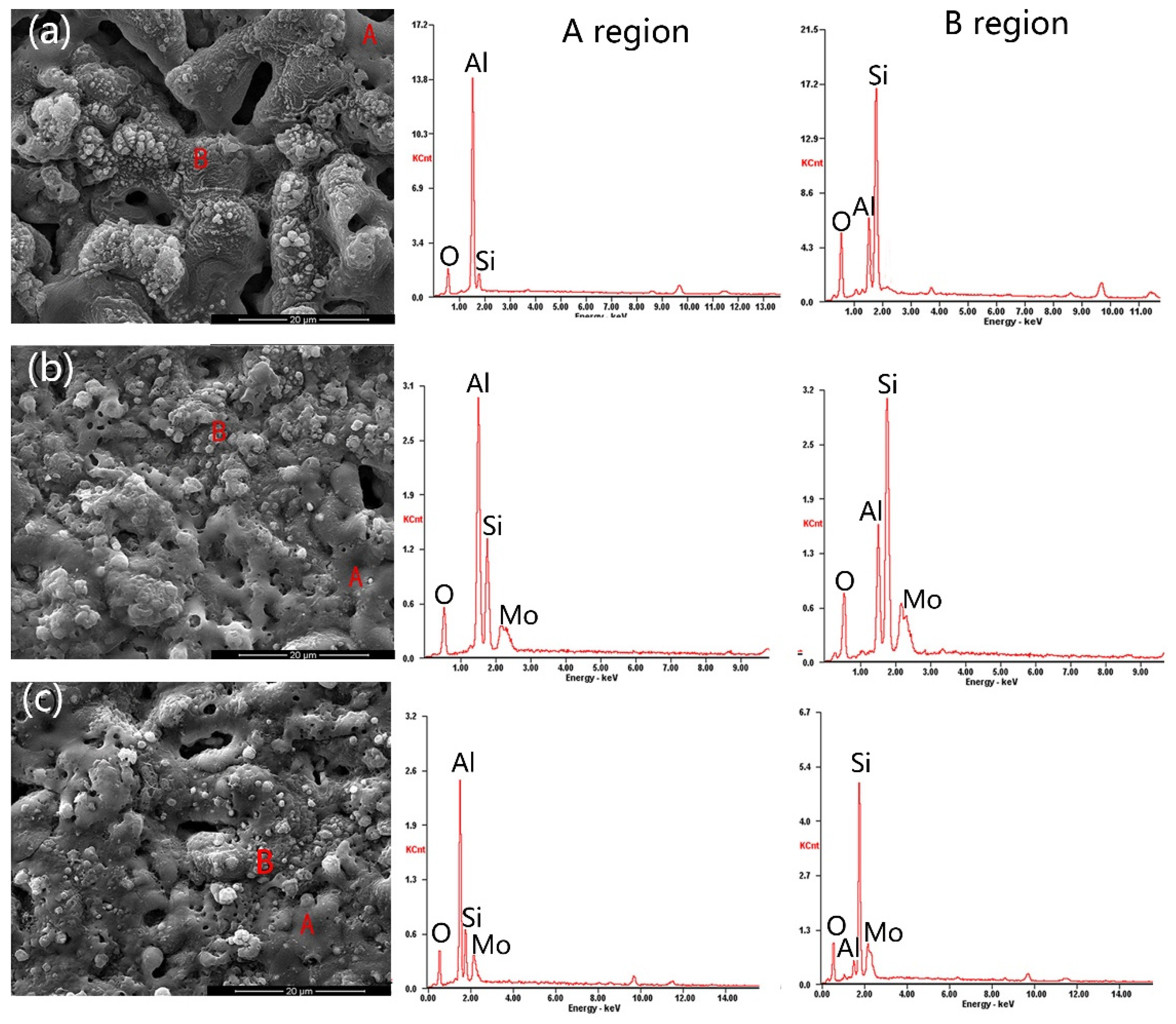
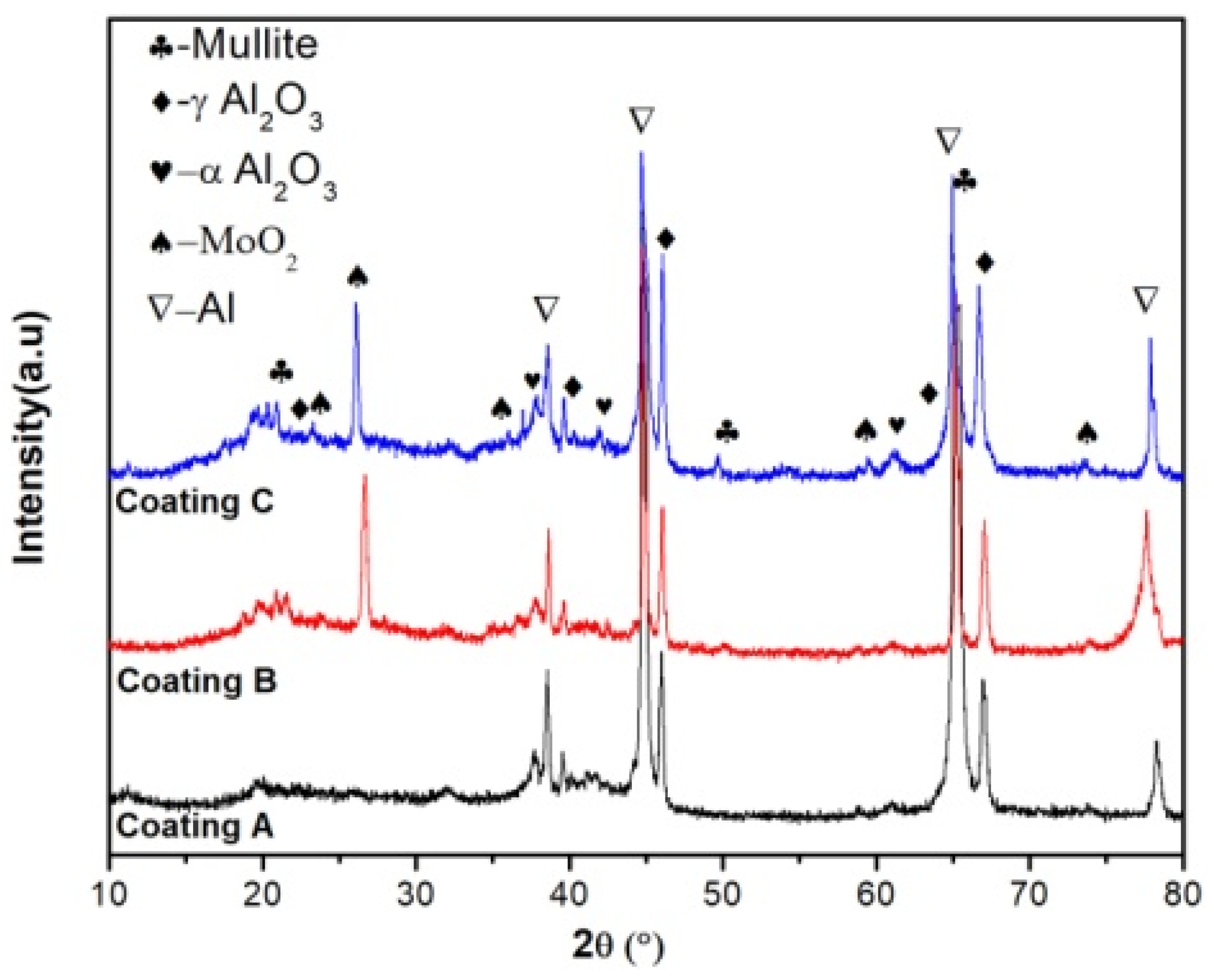
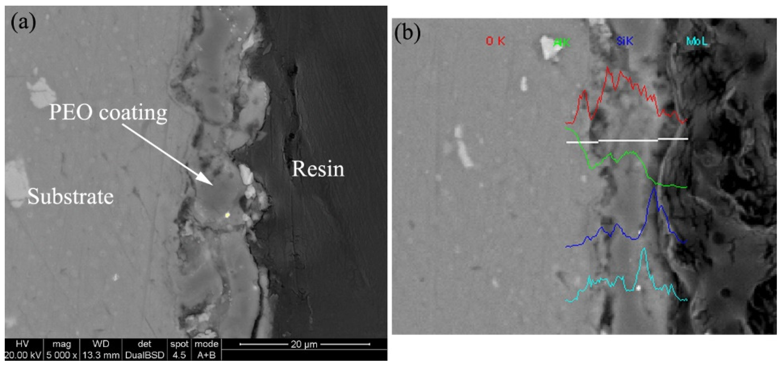
3.1. Microstructure and Phase Composition of the Coatings

With the addition of molybdate in the silicate electrolyte, the surface morphology of MAO coating changed, as shown in Figure 1.
According to Hussein et al. [29], three types of discharges occur during PEO of Al alloys in silicate-based solutions, originating in the upper part of the coating or gases attached to the coating surface, near the alloy/coating interface, or inside pores and cracks of the coatings. Different discharge types lead to different microstructure on the surface of the coating, as indicated by the letters A and B in Figure 1. During the EDS analysis in Figure 1, the Al, Si, O and Mo elements can be detected on the surface of the MAO coatings, where Al is derived from the substrate, while Mo, Si and O are derived from the electrolyte. The distribution of elements in different regions is different. According to EDS analyses, the content of aluminum in region A was much higher than that in region B, and the Al content was significantly reduced, while the contents of Mo, Si and O increased in region B. The coating formation process in region A should be near the alloy/coating interface, and the coating formed in region B originated in the upper part of the coating or gases attached to the coating surface. The cross-section morphology of coating C and the distribution of elements in the cross-section are shown in Figure 2. The distribution of Si, O and Mo elements can be clearly detected. Comparing the surface morphologies of the three coatings in Figure 1a–c, the diameter of the micropores on the coating surface decreases after Na2MoO4 is added to the electrolyte.
In order to clarify the phase composition of the elements identified by EDS analysis in the MAO coating, the samples were analyzed by XRD. The results are shown in Figure 3. Diffraction peaks of α-Al2O3, γ-Al2O3, mullite and aluminum were detectable in all samples. The appearance of strong peaks of aluminum were attributed to the penetration of X-ray into the substrate due to the porous structure of the MAO coating. MoO2 phases were detectable in coatings B and C. The temperature around the discharge channel could reach a very high level [29,30]. This transient high temperature can lead to the conversion of adsorbed SiO32− and MoO42− to oxide, such as SiO2 and MoO2 (Equations (2) and (3)). Meanwhile, the SiO2 would react with molten Al2O3 ejected from the discharge channel, resulting in the formation of mullite, as shown in Equation (4) [31,32]:
2 Al 3 + + 3 O 2 Al 2 O 3
2 SiO 3 2 Δ 2 SiO 2 + O 2 + 4 e
MoO 4 2 Δ MoO 2 + O 2 + 2 e
3 Al 2 O 3 + 2 SiO 2 2773   K 3 Al 2 O 3 2 SiO 2

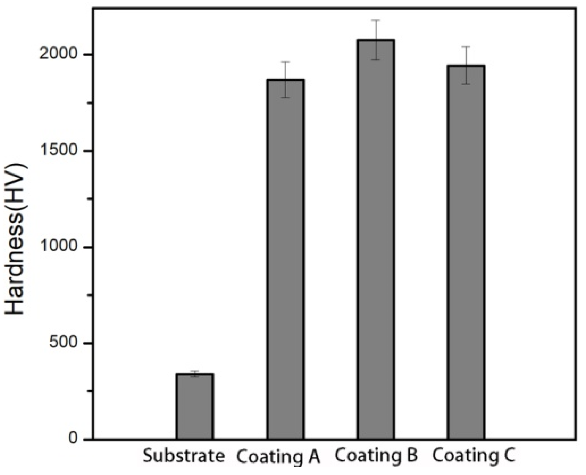
3.2. Hardness Analysis of Al-Zn-Mg-Cu Alloy and Coatings

The coating hardness test was carried out on the cross-section of the PEO outer layer. The nano-hardness of samples is shown in Figure 4. The hardness relates to the microstructure and phase compositions of coatings. The hardness of the Al-Zn-Mg-Cu alloy was about 340 HV. However, after MAO treatment, the hardness of the coating was greatly improved. For the presence of γ-Al2O3, mullite and α-Al2O3 phase in the coatings, the hardness of MAO coatings was greatly increased to 1870 HV. When Na2MoO4 was added to the electrolyte, MoO2 phase was formed in the coating and the hardness of the coatings B and C reached 2077 and 1944 HV, respectively. The increase in hardness may be caused by the change in phase or the change in microstructure. The high hardness can enhance the wear performance.

3.3. Wear Properties

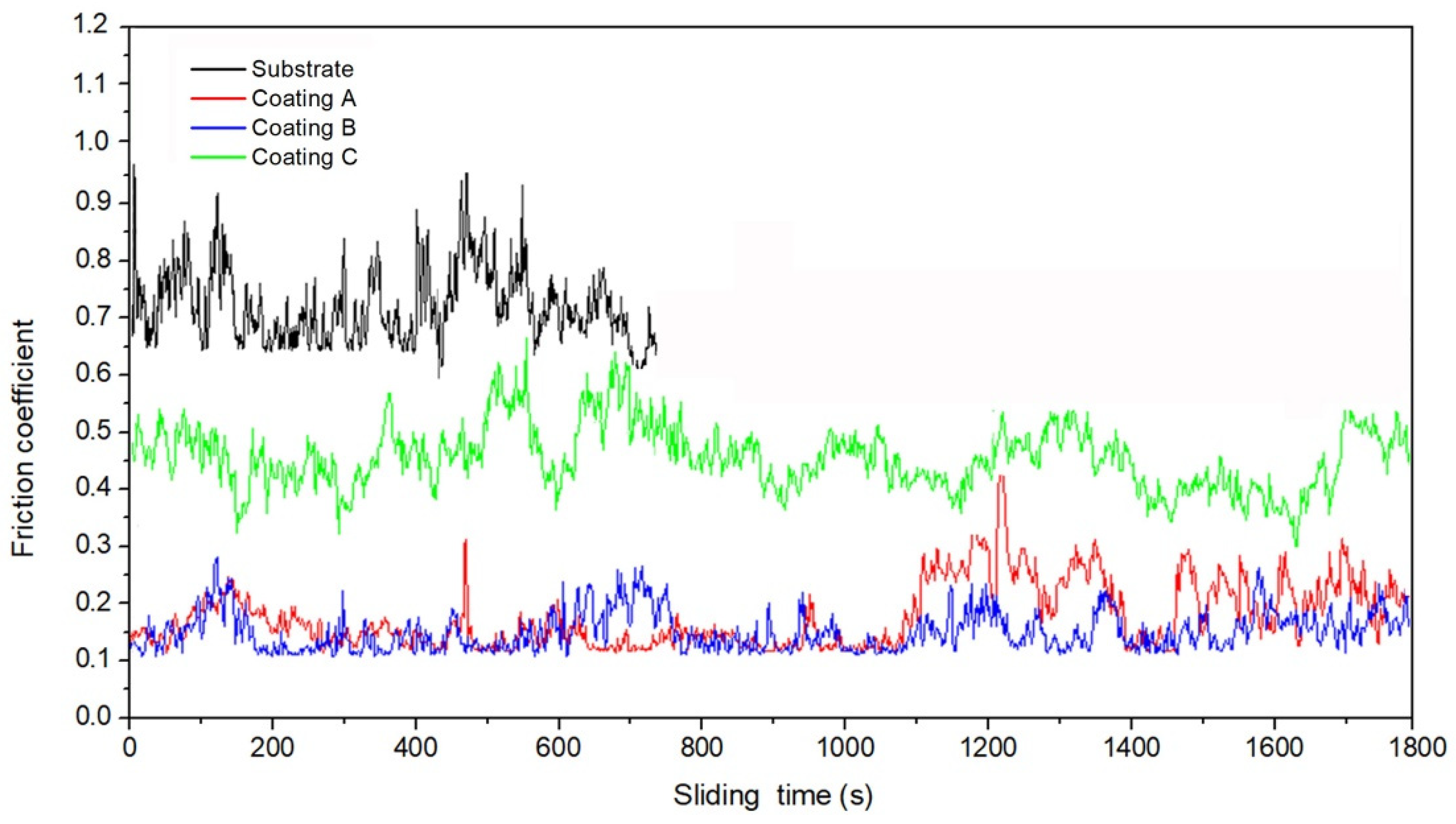
3.3.1. Friction Coefficient

Figure 5 shows that the friction coefficient varies with sliding time for the Al-Zn-Mg-Cu alloy and three coatings. Compared with the friction coefficient of the Al-Zn-Mg-Cu alloy (about 0.7), the friction coefficient of the MAO coatings’ alloy was greatly reduced. For coating A without MoO2 phase, the average value of the friction coefficient was about 0.18, the friction coefficient of coating B was about 0.14 and the friction coefficient of coating C was about 0.45. The differences in the friction coefficients may relate to their different surface microstructures.

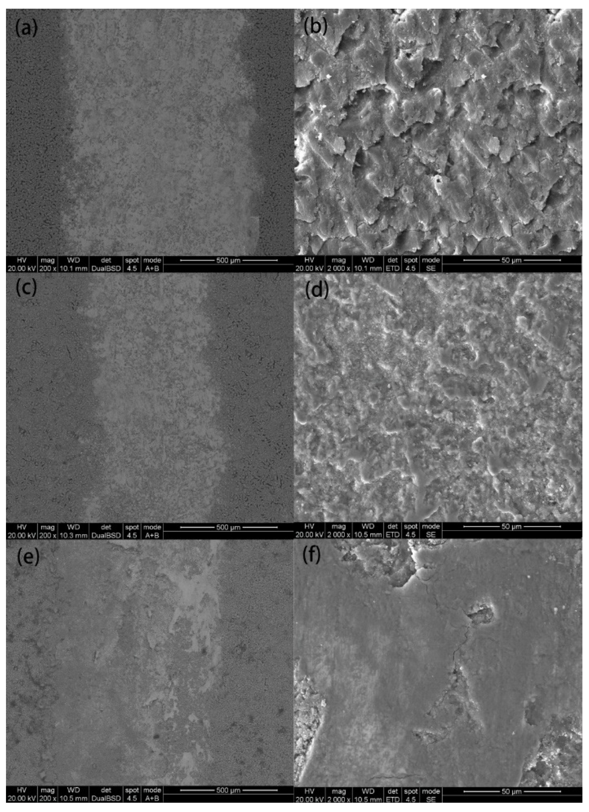
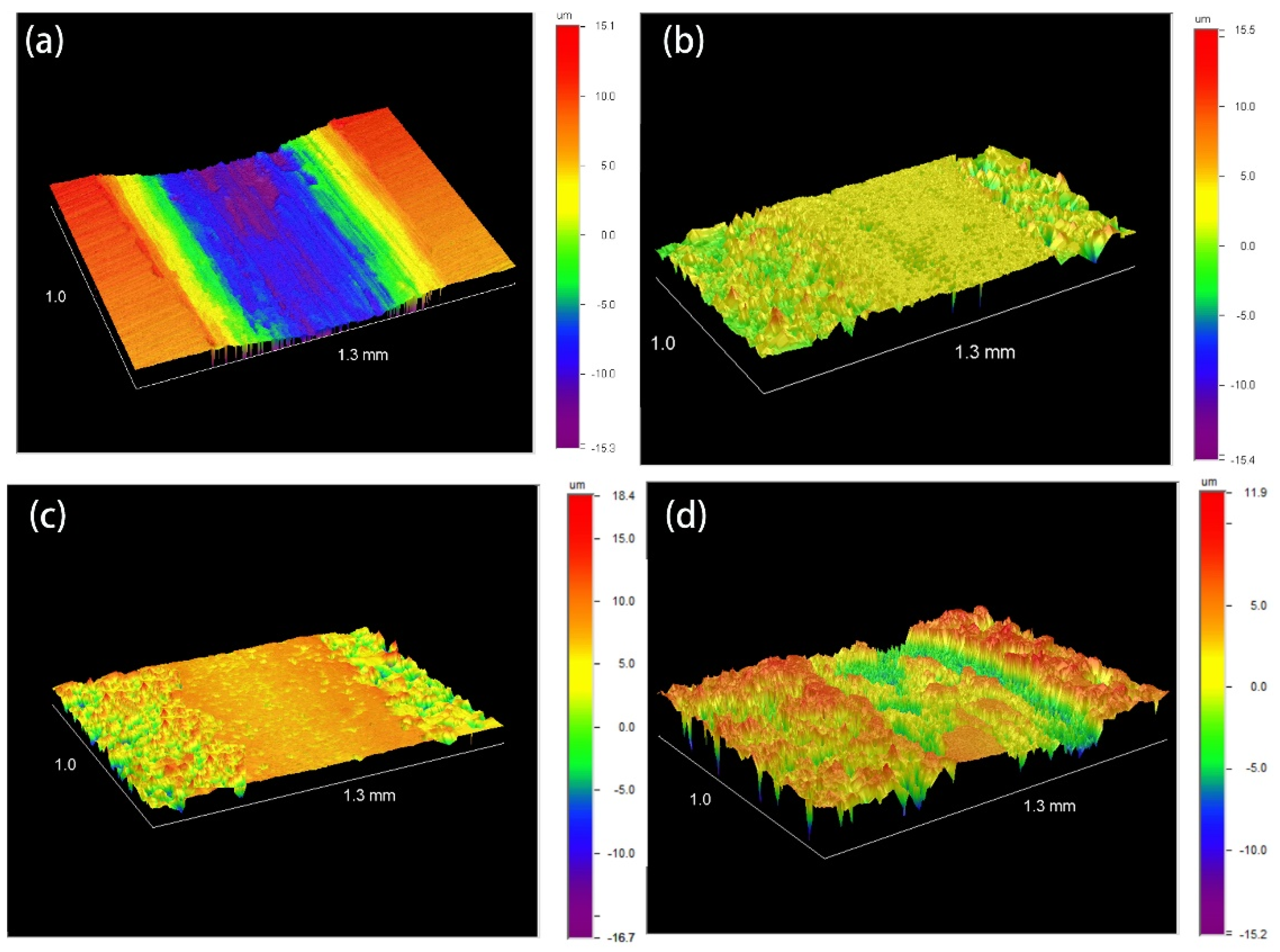
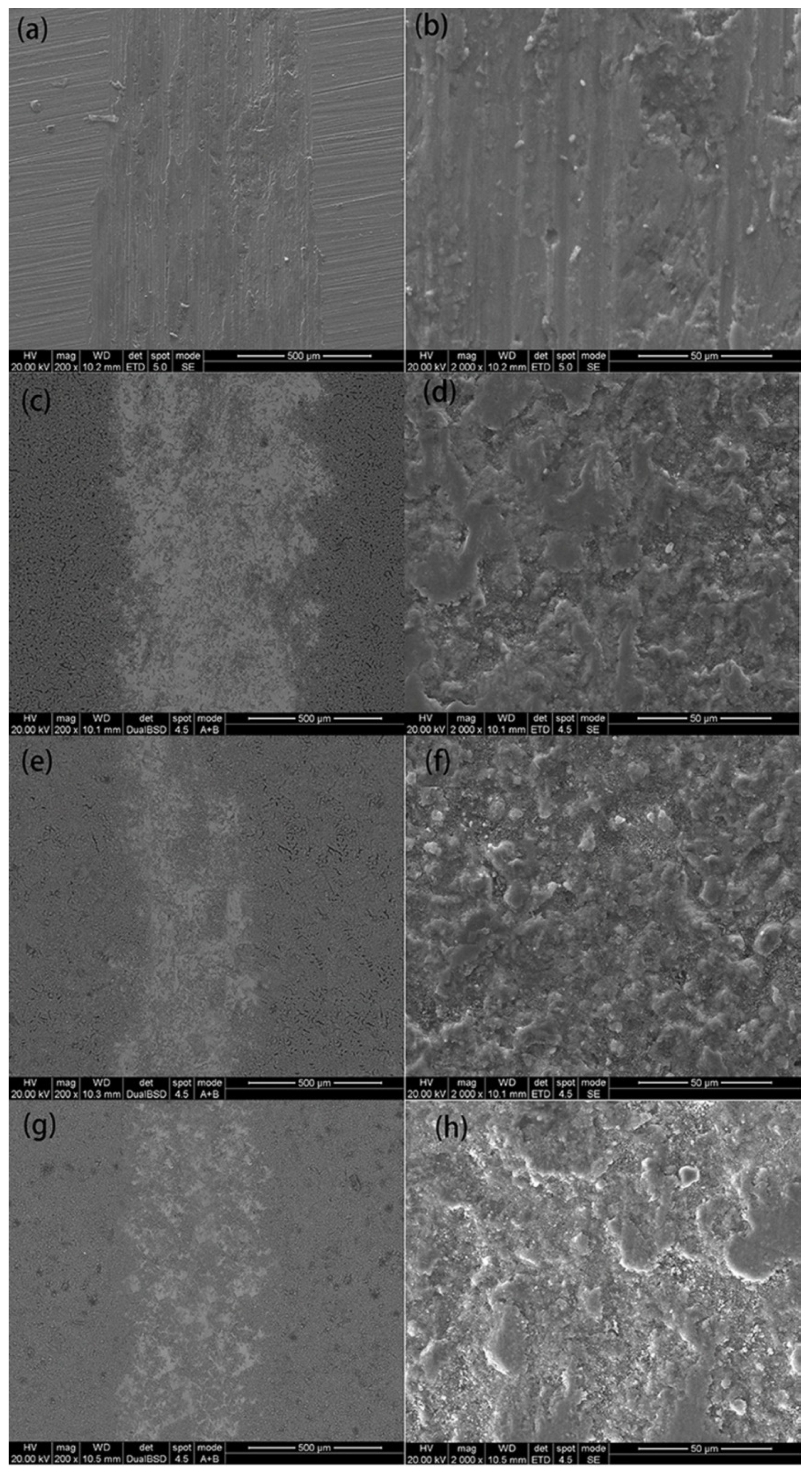
3.3.2. Wear Morphology

The SEM morphologies of the wear tracks of samples after 15 min of wear under 4 N are represented in Figure 6. The approximate distance traveled by the ball during the experiment was 90 m. The wear tracks of the Al-Zn-Mg-Cu alloy revealed damage in the form of longitudinal grooves extending parallel to the sliding direction. However, the wear tracks of the MAO coatings were only covered by the transfer layer, as shown in Figure 6. As the wear proceeded to 30 min, the wear tracks became wider and the tribolayer was destroyed, and then the micro-cracking and coating removal began to appear, as shown in Figure 7. The wear tracks of coating A without molybdenum oxides were almost entirely covered by the tribolayer, which delaminated and fragmented from the surface, as shown in Figure 7b, and the wear track width was wider than the others. The wear tracks of coating B with molybdenum oxides were only covered by the transfer layer, as shown in Figure 7c,d. However, the wear tracks of coating C began to show coating removal, which is mainly related to the looseness and micro-cracks of the coating. The depth of the wear tracks on the MAO coating and the Al-Zn-Mg-Cu alloy after 30 min of wear under 4 N are shown in Figure 8. It indicates that the scratch depth of the MAO coating was much lighter than the substrate, and coating B had the lightest abrasion depth.
This beneficial effect of improving the wear performance of the MAO coating is believed to be associated with the surface characteristics and higher hardness of the coating. After MAO treatment, there were a lot of micro-protrusions on the surface of the coating. During the wear process, the micro-protrusions were subject to the main load, and formed a compact and dense tribolayer by sliding. The tribolayer can provide a protective cover to the underlying material, thus limiting the “metal-to-metal” contact. At the same time, the high hardness of the coating makes it less susceptible to plastic deformation during wear, and the abrasive grains have difficulty penetrating the coating, thereby improving the wear resistance of the alloy.
The wear resistance of the coating can be evaluated by measuring the friction coefficient, wear volume and wear rate. The wear volume can be calculated by Archard’s law [33]:
V s = K F N H
where V is the wear volume, K is the dimensionless wear coefficient, H is the hardness of the softer contact surface, FN is the normal load and S is the sliding distance. The wear resistance of the coating is related to the surface characteristics and the hardness. The higher the hardness, the lower the wear volume and the better the wear resistance. When 3 g/L Na2MoO4 was added to the electrolyte, the hardness of coating B reached 2077 HV, and the friction coefficient of coating B was also the smallest of the three. According to the formula, coating B has the smallest wear volume, which is consistent with the experimental results, as shown in Figure 6, Figure 7 and Figure 8.

4. Conclusions

To improve the wear properties of the Al-Zn-Mg-Cu alloy, in this study, Al2O3-MoO2-SiO2 composite coatings were formed through DC MAO treatment in a silicate electrolyte containing Na2MoO4. The diameter of the micropores on the coating surface decreased after Na2MoO4 was added to the electrolyte. SiO32− and MoO42− in solution participated in reactions during micro-arc oxidation, and conversion to oxide under high temperatures. The coatings formed in the electrolyte with Na2MoO4 consisted of α-Al2O3, γ-Al2O3, mullite and MoO2. When 3 g/L of Na2MoO4 was added into the electrolyte, the hardness increased from 1870 to 2077 HV, the friction coefficient decreased from 0.18 to 0.14 and it showed the lightest depth of the wear tracks.

Author Contributions

Data curation, D.Z.; Formal analysis, D.Z.; Funding acquisition, Z.L. and H.W.; Methodology, D.Z.; Project administration, Z.L. and L.Z.; Software, D.Z.; Writing—original draft, D.Z.; Writing—review and editing, D.Z., L.Z. and H.W. All authors have read and agreed to the published version of the manuscript.

Funding

The authors are grateful for financial support from the Scientific Research Fund of Hunan Provincial Education Department (20K112); Research Fund of the Education Department of Hunan Province, China (18B421); National Key Research and Development Program of China (2016YFB0300900); The Opening Foundation Key Laboratory of Hunan Province for Efficient Power System and Intelligent Manufacturing (No. 19KF01).

Institutional Review Board Statement

Not applicable.

Informed Consent Statement

Not applicable.

Data Availability Statement

Not applicable.

Conflicts of Interest

There are no conflicts of interest to declare.

References

  1. Gelfgat, M.Y.; Basovich, V.S.; Adelman, A. Aluminum alloy tubules for the oil and gas industry. World Oil 2006, 227, 45–51. [Google Scholar]
  2. Feng, C.; Shou, W.B.; Liu, H.Q.; Yi, D.Q.; Feng, Y.R. Microstructure and mechanical properties of high strength Al−Zn−Mg−Cu alloys used for oil drill pipes. Trans. Nonferrous Met. Soc. China 2015, 25, 3515–3522. [Google Scholar] [CrossRef]
  3. Liang, J.; Peng, L.; Sun, J.H.; Zhang, Y.Q.; Peng, L. Development of aluminum alloy drill rod material in geological drilling and the indoor experimental study. Geol. Explor. 2011, 47, 304–308. [Google Scholar]
  4. Arsenault, B.; Simard, S.; Marcoux, P.; Ghali, E. Stress Corrosion Cracking Mitigation of 7075-T6 Aluminium Alloy by Thermal Spray Coating. In Proceedings of the NACE International Corrosion Conference 2006, San Diego, CA, USA, 12–16 March 2006. [Google Scholar]
  5. Yan, T.N.; Xue, W.; Lan, K. High reliability aluminum alloy drill pipe and its application in super-deep wells and extended-reach wells. Geolog. Sci. Technol. Inform. 2010, 29, 112–115. [Google Scholar]
  6. Wernick, S.; Pinner, R.; Sheasby, P.G. The Surface Treatment and Finishing of Aluminum and Its Alloys; Finishing Publications Ltd.: Warrington, UK, 1987. [Google Scholar]
  7. Henley, V.F. Anodic Oxidation of Aluminium & Its Alloys; Pergamon Press: Oxford, UK, 1982. [Google Scholar]
  8. Sherif, E.M.; Park, S.M. Effects of 1, 5-naphthalenediol on aluminium corrosion as a corrosion inhibitor in 0.50 M NaCl. Electrochem. Soc. 2005, 152, B205–B211. [Google Scholar] [CrossRef] [Green Version]
  9. Li, T.; Li, X.G.; Dong, C.F.; Cheng, Y.F. Characterization of atmospheric corrosion of 2A12 aluminum alloy in tropical marine environment. J. Mater. Eng. Perform. 2010, 19, 591–598. [Google Scholar] [CrossRef]
  10. Abdul, S.R.; Rita, M.; Katiyar, P.K.; Kantesh, B. Superhydrophobic, self-cleaning carbon nanofiber CVD coating for corrosion protection of AISI 1020 steel and AZ31 magnesium alloys. Surf. Coat. Technol. 2020, 404, 126421. [Google Scholar]
  11. Chen, L.; Zeng, D.P.; Liu, Z.Y.; Bai, S.; Li, J. Improving the fatigue crack propagation resistance and damage tolerance of 2524-T3 alloy with amorphous electroless Ni-P coating. J. Mater. Eng. Perform. 2018, 27, 881–888. [Google Scholar] [CrossRef]
  12. Wojciechowski, J.J.; Szubert, K.; Peipmann, R.; Fritz, M.; Schmidt, U.; Bund, A.; Lota, G. Anti-corrosive properties of silane coatings deposited on anodised aluminium. Electrochim. Acta 2016, 220, 1–10. [Google Scholar] [CrossRef]
  13. Brusciotti, F.; Darya, V.; Xue, M.H.; Montemor, F.; Lamaka, S.; Ferreira, M. Hybrid epoxy-silane coating for improved corrosion protection of Mg alloy. Corros. Sci. 2013, 67, 82–90. [Google Scholar] [CrossRef]
  14. Sobolev, A.; Peretz, T.; Borodianskiy, K. Synthesis and growth mechanism of ceramic coatings on an Al-Cu alloy using plasma electrolytic oxidation in molten salt. J. Alloys Compd. 2021, 869, 159309. [Google Scholar] [CrossRef]
  15. Sieber, M.; Mehner, T.; Dietrich, D.; Alisch, G.; Nickel, D.; Meyer, D.; Scharf, I.; Lampke, T. Wear-resistant coatings on aluminium produced by plasma anodizing-A correlation of wear properties, microstructure, phasecomposition and distribution. Surf. Coat. Technol. 2014, 240, 96–102. [Google Scholar] [CrossRef]
  16. Lin, M.; Nemcova, A.; Voevodin, A.A.; Korenyi-Both, A.; Liskiewicz, T.W.; Laugel, N.; Matthews, A.; Yerokhin, A. Surface characteristics underpinning fretting wear performance of heavily loaded duplex chameleon/PEO coatings on Al. Tribol. Int. 2021, 154, 106723. [Google Scholar] [CrossRef]
  17. Sobolev, A.; Peretz, T.; Borodianskiy, K. Fabrication and characterization of ceramic coating on Al7075 alloy by plasma electrolytic oxidation in molten salt. Coatings 2020, 10, 993. [Google Scholar] [CrossRef]
  18. Hakimizad, A.; Raeissi, K.; Golozar, M.A. The effect of pulse waveforms on surface morphology, composition and corrosion behavior of Al2O3 and Al2O3/TiO2 nano-composite PEO coatings on 7075 aluminum alloy. Surf. Coat. Technol. 2017, 324, 208–221. [Google Scholar] [CrossRef]
  19. Ling-Yun, A.N.; Ying, M.A.; Yan, X.X.; Wang, S.; Wang, Z.-Y. Effects of electrical parameters and their interactions on plasma electrolytic oxidation coatings on aluminum substrates. Trans. Nonferrous Met. Soc. China 2020, 30, 883–895. [Google Scholar]
  20. Baratia, N.; Meletisb, E.I.; Farda, F.G.; Yerokhin, A.; Rastegari, S.; Faghihi-Sani, M.A. Al2O3–ZrO2 nanostructured coatings using DC plasma electrolyticoxidation to improve tribological properties of Al substrates. Appl. Surf. Sci. 2015, 356, 927–934. [Google Scholar] [CrossRef]
  21. Vatan, H.N.; Kahrizsangi, R.E.; Asgarani, M.K. Structural, tribological and electrochemical behavior of SiC nanocomposite oxide coatings fabricated by plasma electrolytic oxidation (PEO) on AZ31 magnesium alloy. J Alloys Compd. 2016, 683, 241–255. [Google Scholar] [CrossRef]
  22. Krishna, L.R.; Gupta, P.S.V.N.B.; Sundararajan, G. The influence of phase gradient within the micro arc oxidation (MAO) coatings on mechanical and tribological behaviors. Surf Coat. Technol. 2015, 269, 54–63. [Google Scholar] [CrossRef]
  23. Guo, Y.; Wei, Z.; Wei, D.; Ma, D.; Lu, X.; Zhu, X. Fabrication of WO3/Al2O3 composite ceramic coatings on 6063 aluminum alloy by ultrasound-enhanced micro-arc oxidation. Int. J. Electrochem. Sci. 2021, 16, 21063. [Google Scholar] [CrossRef]
  24. Hadraba, H.; Drdlik, D.; Chlup, Z.; Maca, K.; Dlouhy, I.; Cihlar, J. Laminated alumina/zirconia ceramic composites prepared by electrophoretic deposition. J. Eur. Ceram. Soc. 2012, 32, 2053–2056. [Google Scholar] [CrossRef]
  25. Polat, A.; Makaraci, M.; Usta, M. Influence of sodium silicate concentration on structural and tribological properties of microarc oxidation coatings on 2017A aluminum alloy substrate. J. Alloys Compd. 2010, 504, 519–526. [Google Scholar] [CrossRef]
  26. Li, Z.J.; Yuan, Y.; Jing, X.Y. Comparison of plasma electrolytic oxidation coatings on Mg-Li alloy formed in molybdate/silicate and aluminate/silicate composite electrolytes. Mater. Corros. 2014, 65, 493–501. [Google Scholar] [CrossRef]
  27. Kaseem, M.; Kamil, M.P.; Ko, Y.G. Electrochemical response of MoO2-Al2O3 oxide films via plasma electrolytic oxidation. Surf. Coat. Technol. 2017, 322, 163–173. [Google Scholar] [CrossRef]
  28. Javidi, M.; Fadaee, H. Plasma electrolytic oxidation of 2024-T3 aluminum alloy andinvestigation on microstructure and wear behavior. Appl. Surf. Sci. 2013, 286, 212–219. [Google Scholar] [CrossRef]
  29. Hussein, R.; Nie, X.; Northwood, D.; Yerokhin, A.; Matthews, A. Spectroscopic study of electrolytic plasma and discharging behaviour during the plasma electrolytic oxidation (PEO) process. Appl. Phys. 2010, 43, 105203. [Google Scholar] [CrossRef]
  30. Kang, M.L.; Byung, U.L.; Sang, Y.; Eung, S.L.; Bongyoung, Y.; Dong, H.S. Evaluation of plasma temperature during plasma oxidation processing of AZ91 Mg alloy through analysis of the melting behavior of incorporated particles. Electrochim. Acta 2012, 67, 6–11. [Google Scholar]
  31. Dehnavi, V.; Liu, X.Y.; Luan, B.L.; Shoesmith, D.W.; Rohani, S. Phase transformation in plasma electrolytic oxidation coatings on 6061 aluminum alloy. Surf. Coat. Technol. 2014, 251, 106–114. [Google Scholar] [CrossRef]
  32. Wang, K.; Koo, B.H.; Lee, C.G.; Kim, Y.-J.; Lee, S.-H.; Byon, E. Effects of electrolytes variation on formation of oxide layers of 6061 al alloys by plasma electrolytic oxidation. Trans. Nonferrous Met. Soc. China 2009, 19, 866–870. [Google Scholar] [CrossRef]
  33. Archard, J.F. Contact and rubbing of flat surfaces. J. Appl. Phys. 1953, 24, 981–988. [Google Scholar] [CrossRef]
Figure 1. SEM morphologies and EDS of the MAO coatings: (a) coating A, (b) coating B, (c) coating C.
Coatings 11 00915 g001
Figure 2. (a) Cross-section morphology of coating C, and (b) distribution of elements of coating C.
Coatings 11 00915 g002
Figure 3. XRD patterns of the MAO coatings.
Coatings 11 00915 g003
Figure 4. Vickers hardness of different samples.
Coatings 11 00915 g004
Figure 5. Friction coefficient of substrate and three coatings versus the sliding time.
Coatings 11 00915 g005
Figure 6. SEM morphologies of the wear tracks after 15 min of wear under 4 N: (a,b) Al-Zn-Mg-Cu alloy, (c,d) coating A, (e,f) coating B and (g,h) coating C.
Coatings 11 00915 g006
Figure 7. SEM morphologies of the wear tracks after 30 min of wear under 4 N: (a,b) coating A, (c,d) coating B and (e,f) coating C.
Coatings 11 00915 g007
Figure 8. Profilometer images of wear tracks after 30 min of wear under 4 N: (a) Al-Zn-Mg-Cu alloy, (b) coating A, (c) coating B and (d) coating C.
Coatings 11 00915 g008
Table 1. Chemical composition of investigated alloys (wt.%).
ZnMgCuCrFeSiAl
6.282.191.60.150.4–0.60.4–0.6Bal.
Publisher’s Note: MDPI stays neutral with regard to jurisdictional claims in published maps and institutional affiliations.

