
Isothermal Oxidation Performance of Laser Cladding Assisted with Preheat (LCAP) Tribaloy T-800 Composite Coatings Deposited on EN8


Abstract
:1. Introduction
2. Materials and Methods
3. Results and Discussion
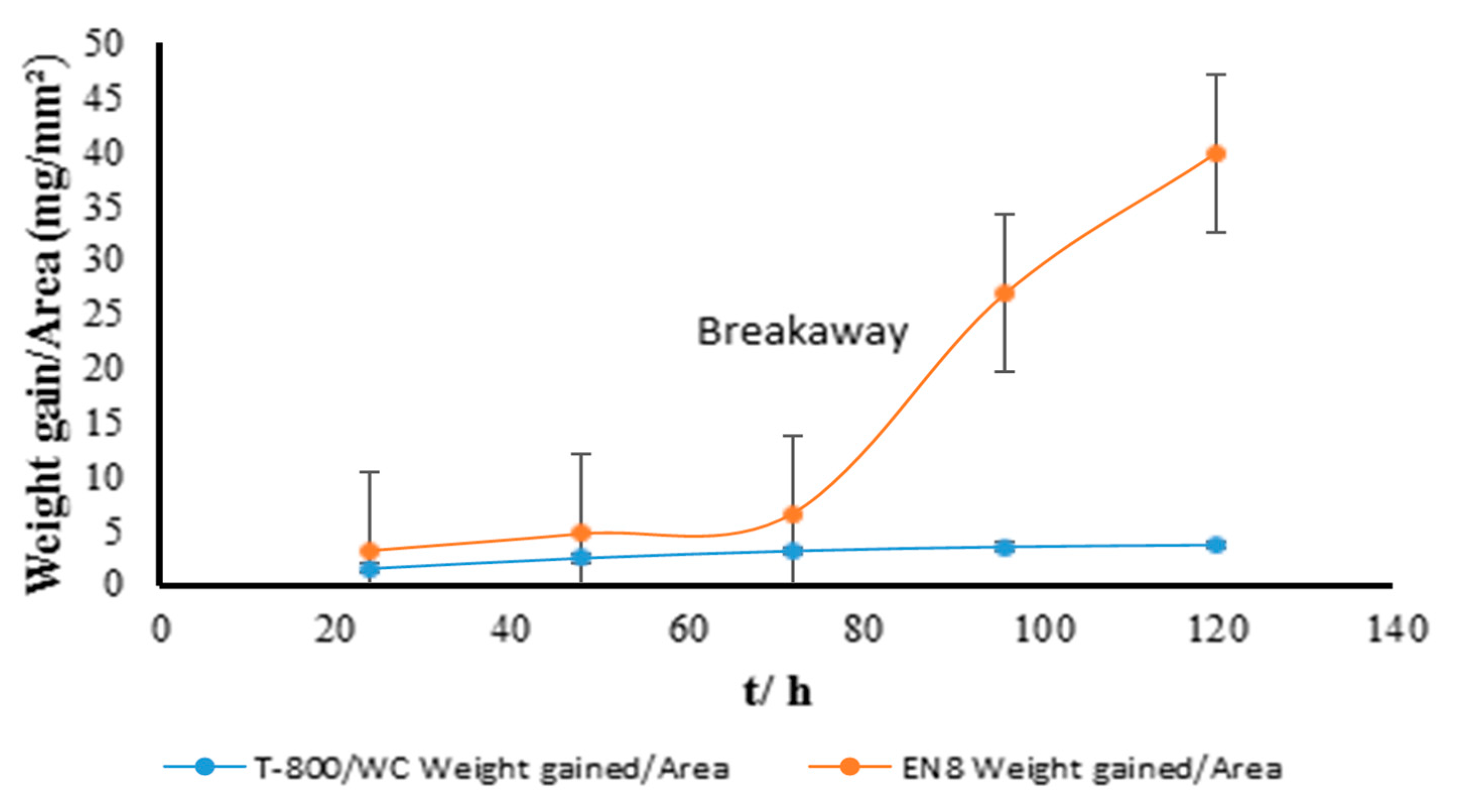
3.1. Gravimetric Analysis of the Oxidation Behaviour of the EN8 Substrate and T-800/WC Coating at 800 °C
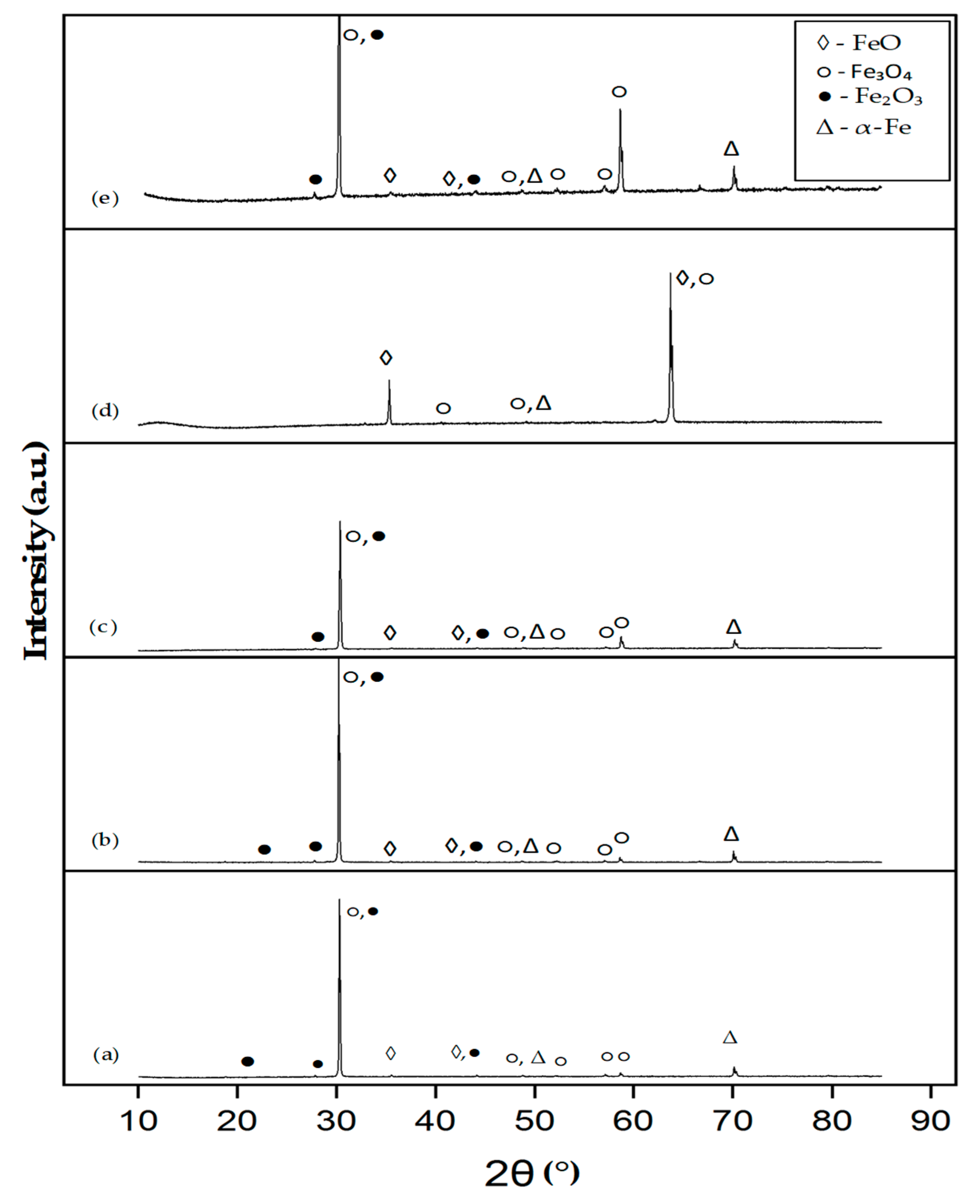
3.2. Phase Analysis of the T-800/WC Coating and EN8 Oxides
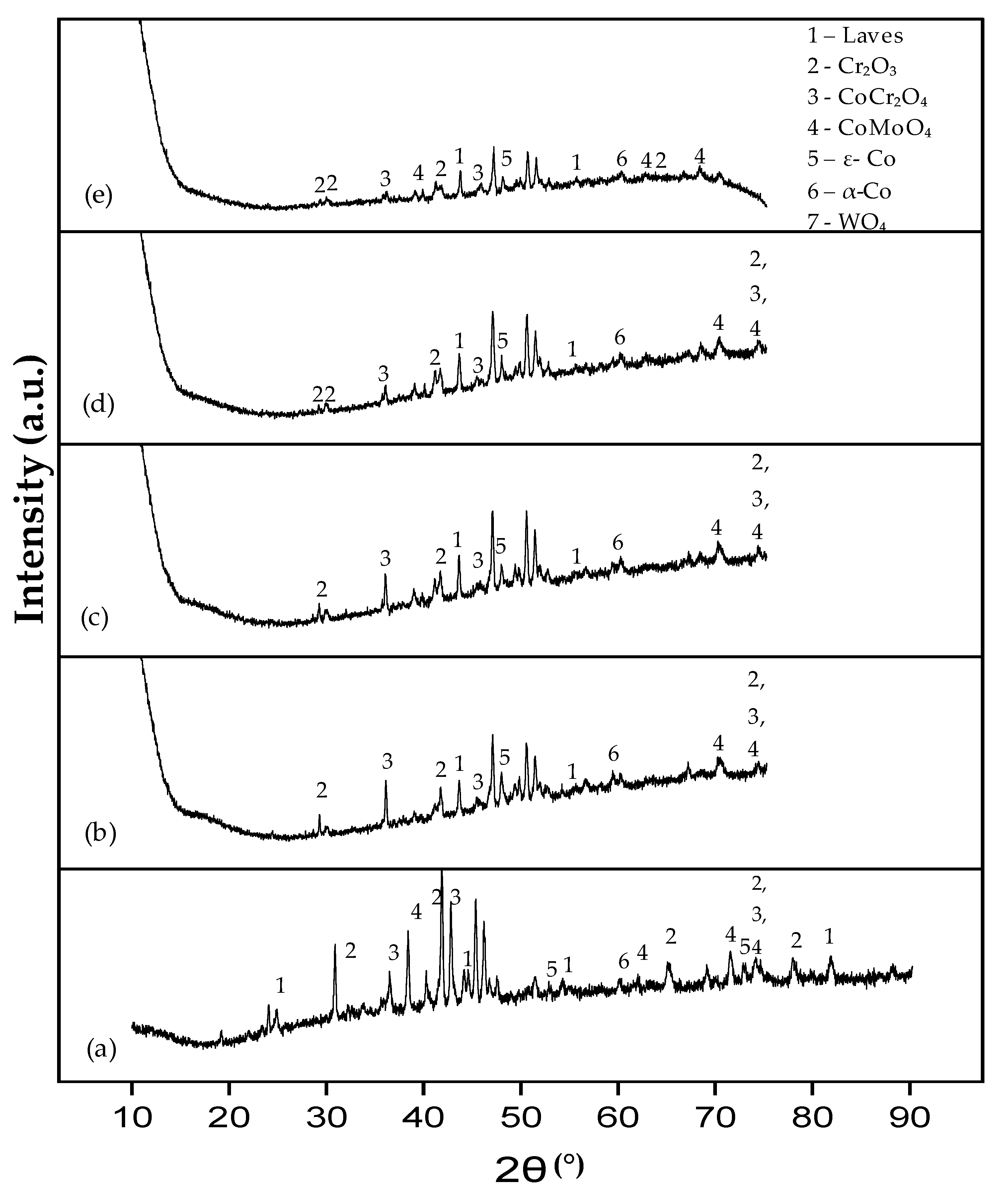
3.2.1. Phase Analysis (XRD) of EN8
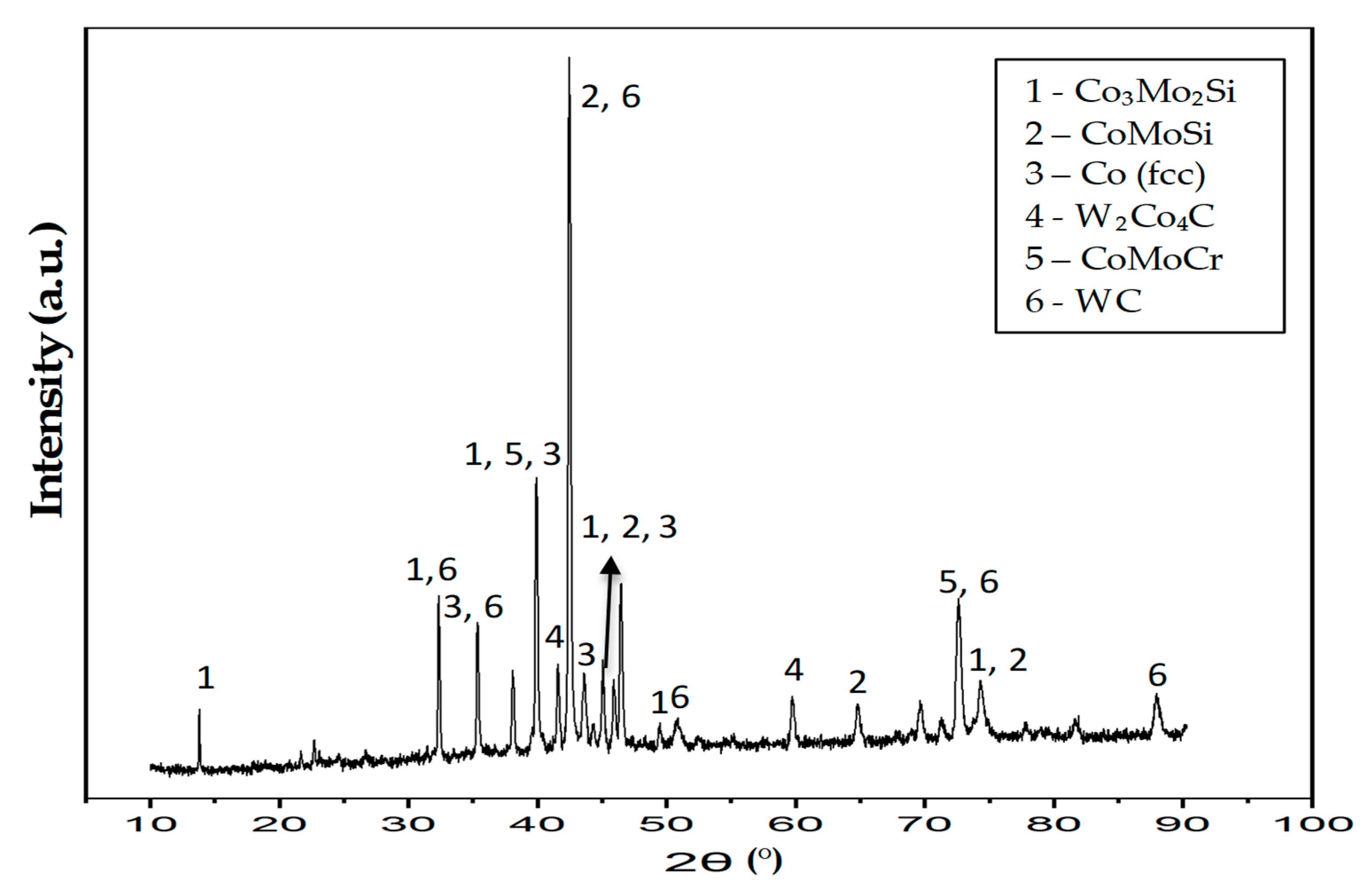
3.2.2. Phase Analysis (XRD) of the T-800/WC Coating
3.3. Surface Morphologies and Chemical Composition of Oxide Scales on the Uncoated and EN8 Substrates
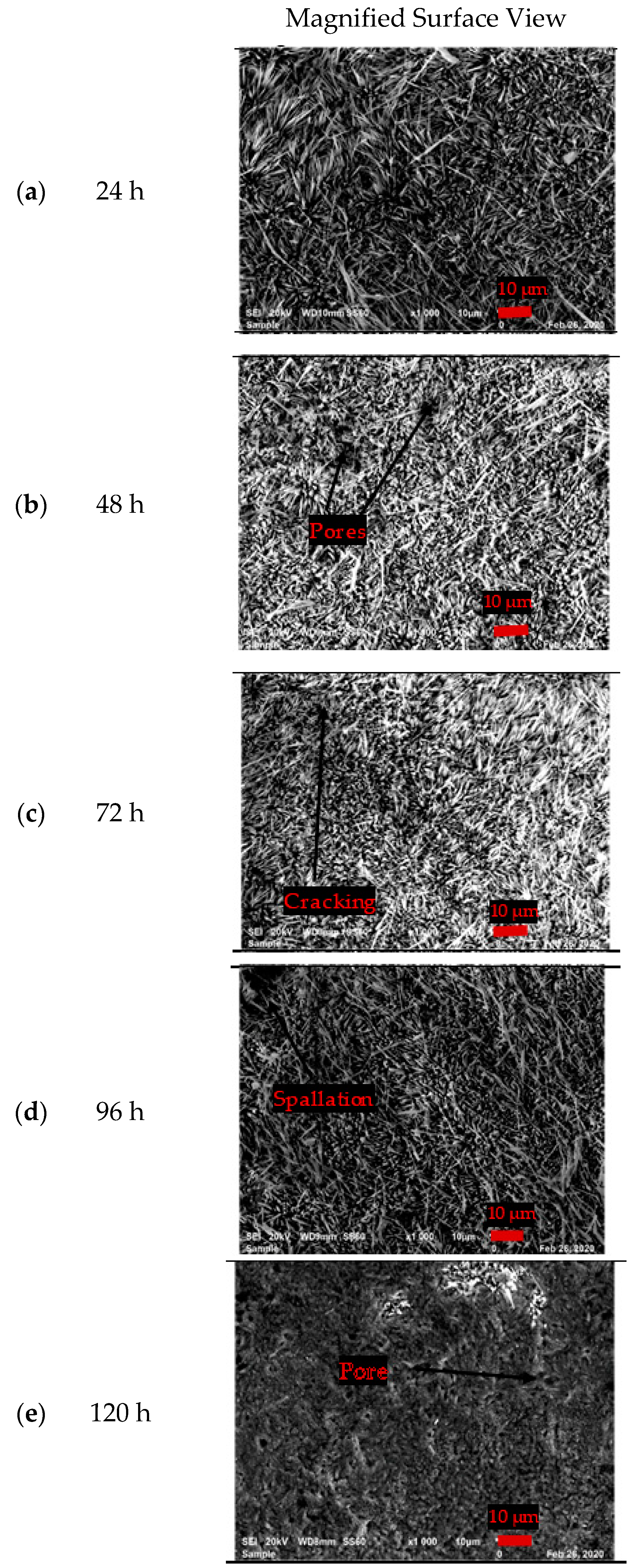
3.3.1. Surface Morphology of the Uncoated EN8 Substrate
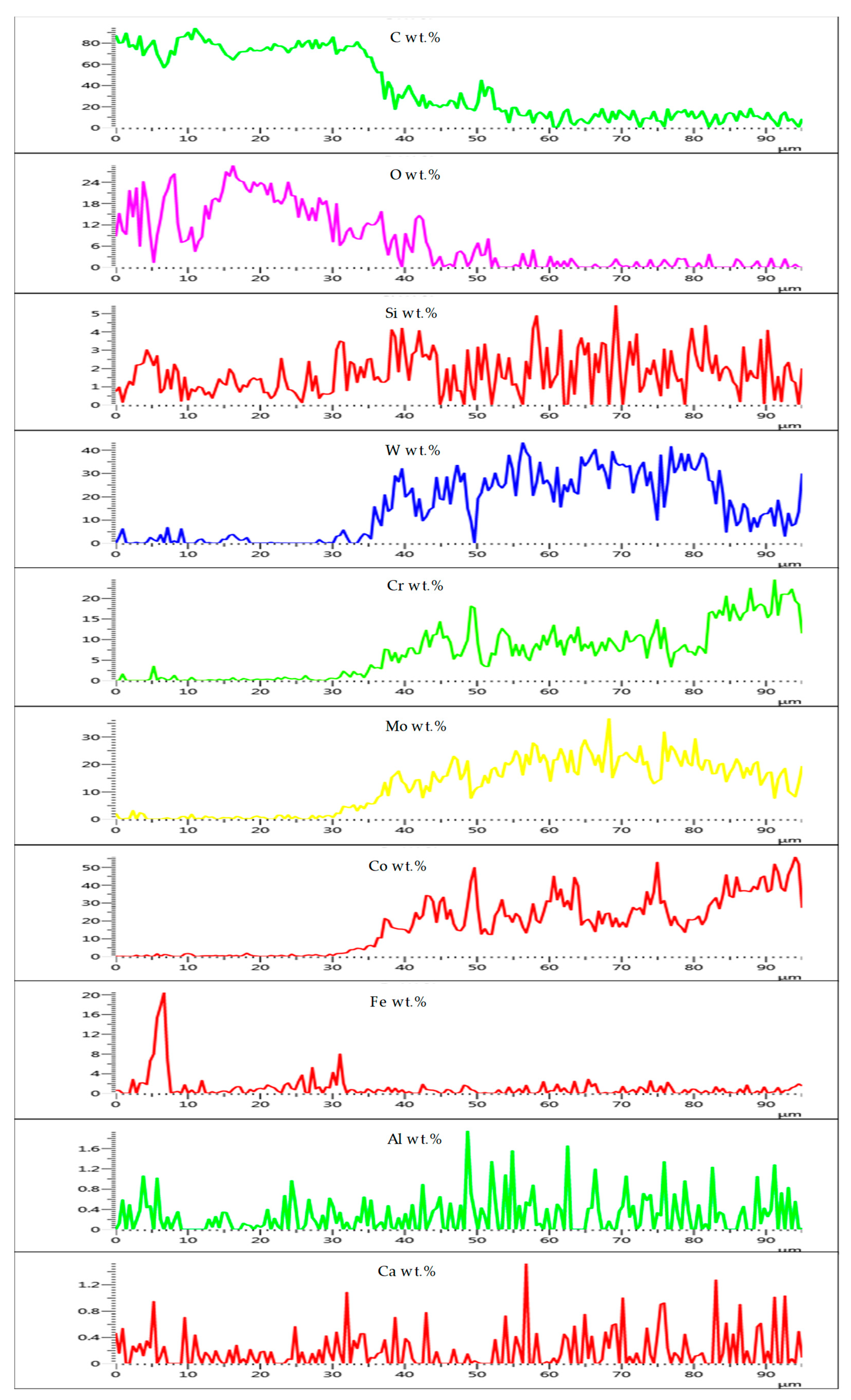
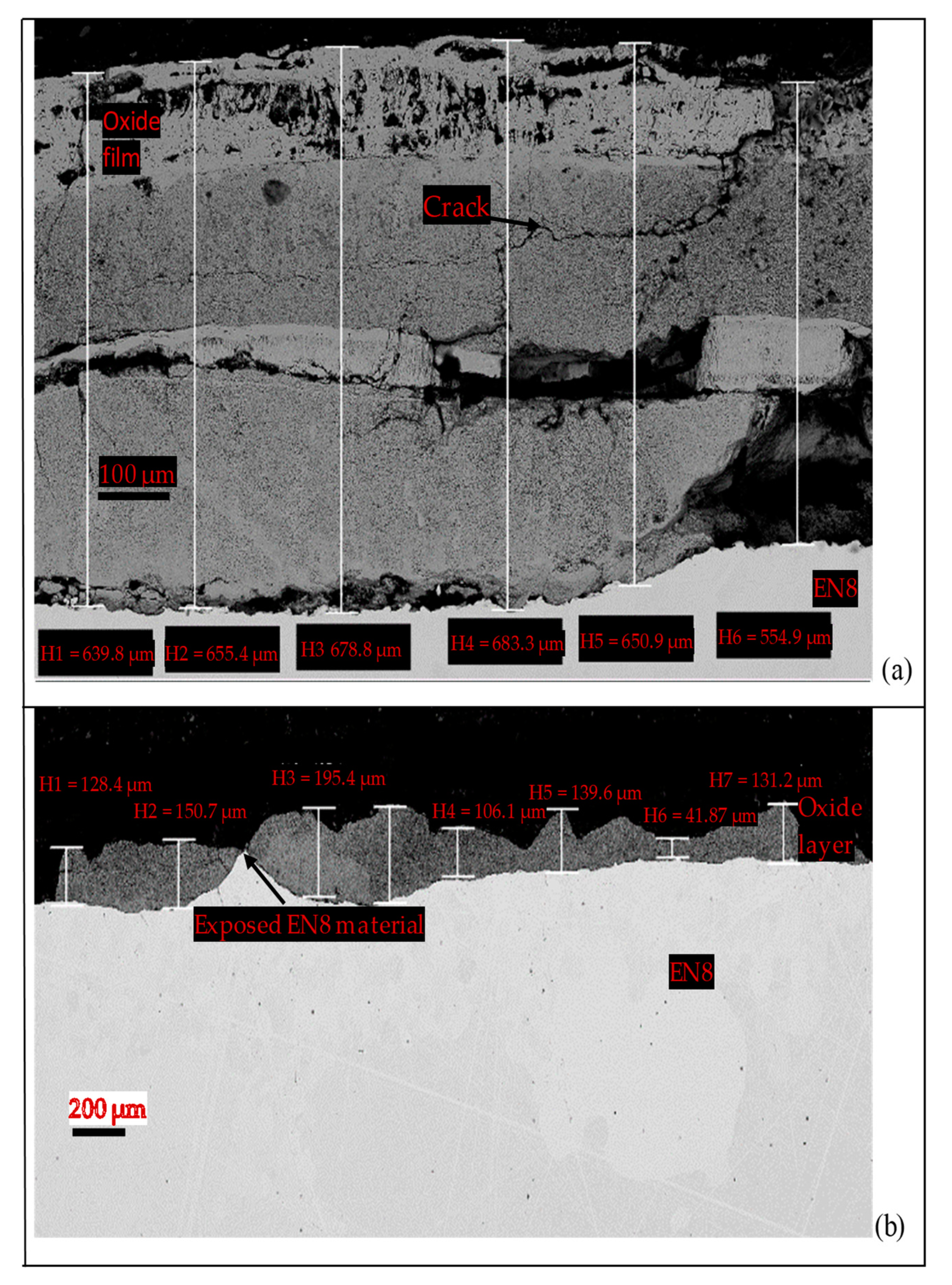
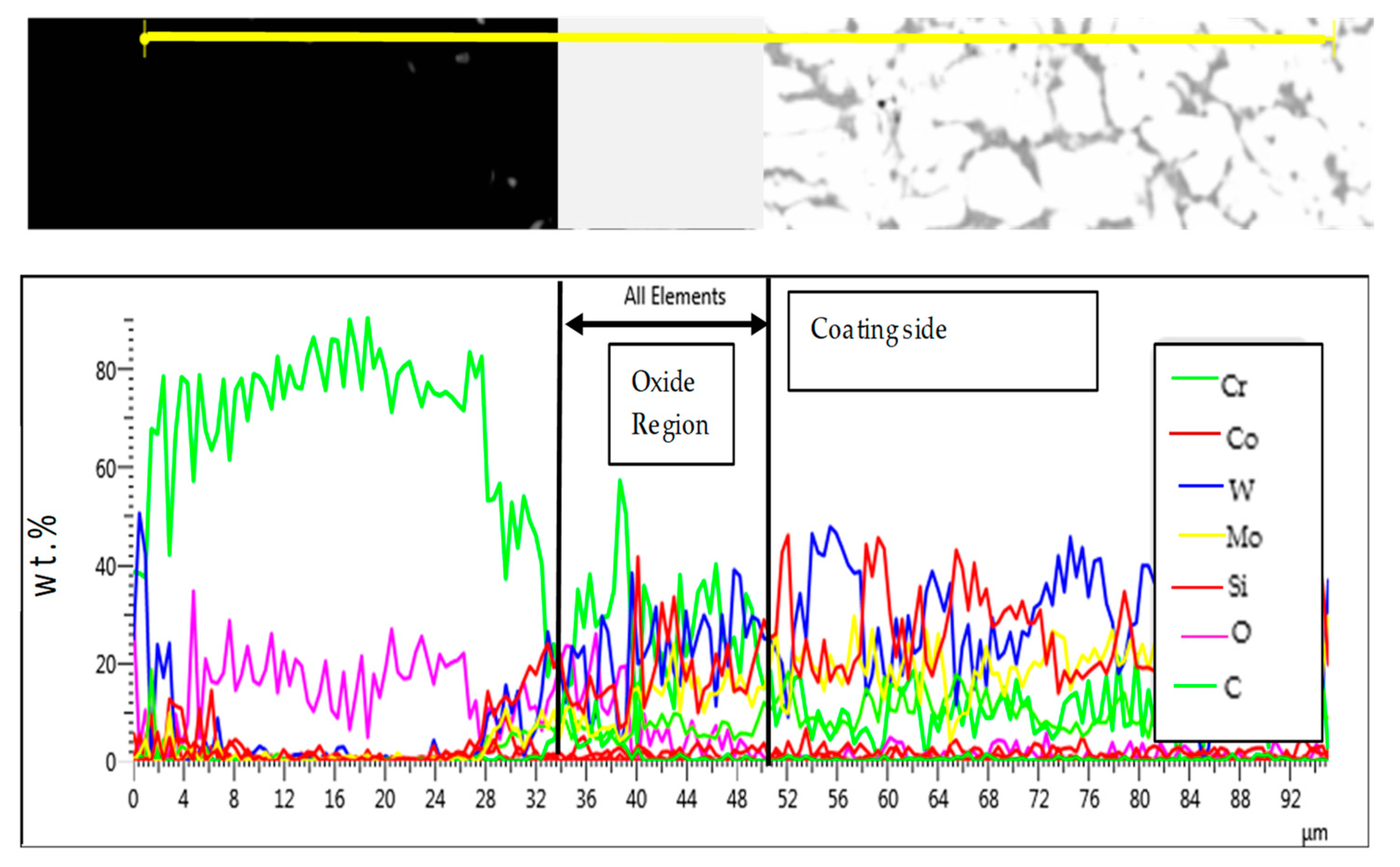
3.3.2. Comparative Analysis of the Cross-Sectional View and EDS Analysis of EN8 and the T-800/WC Coating
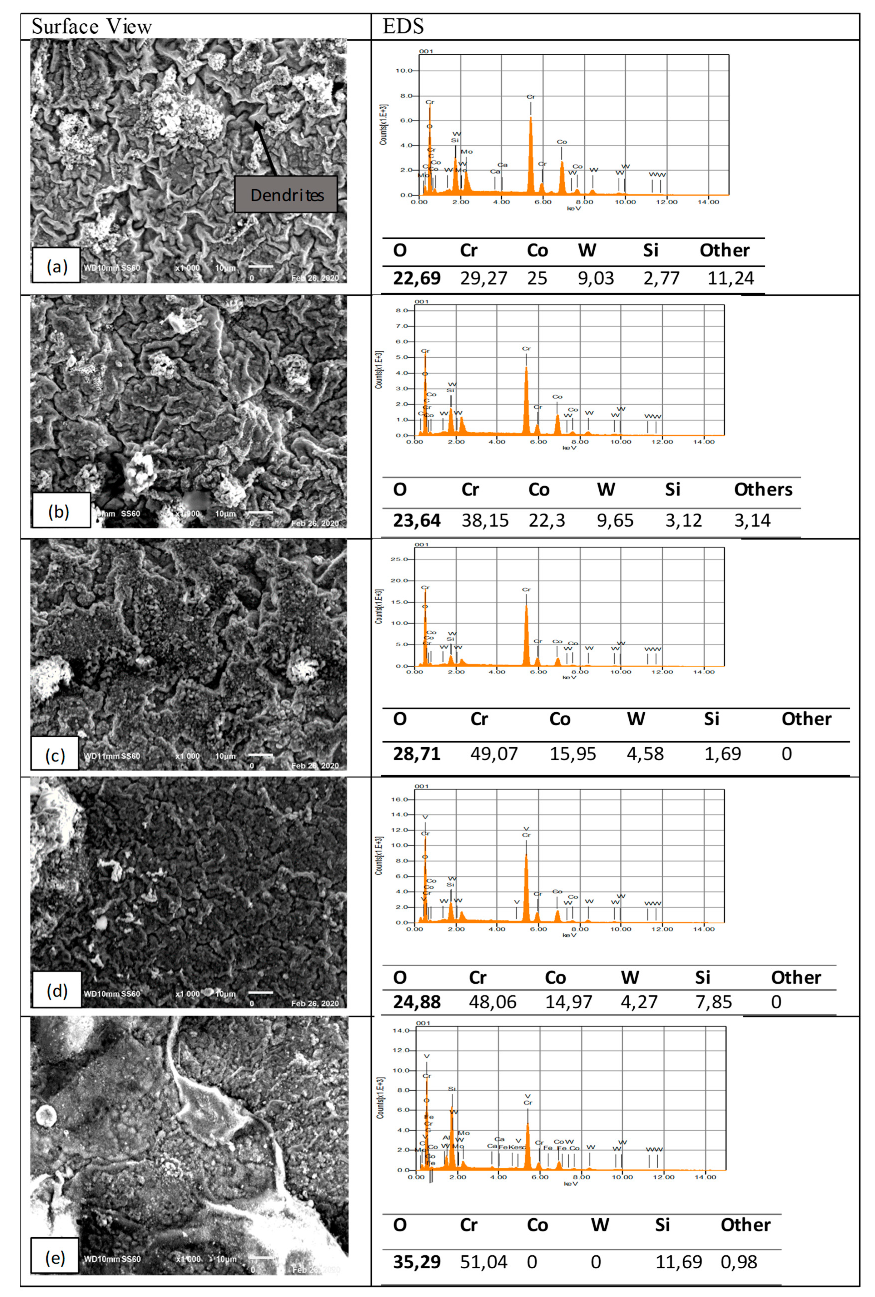
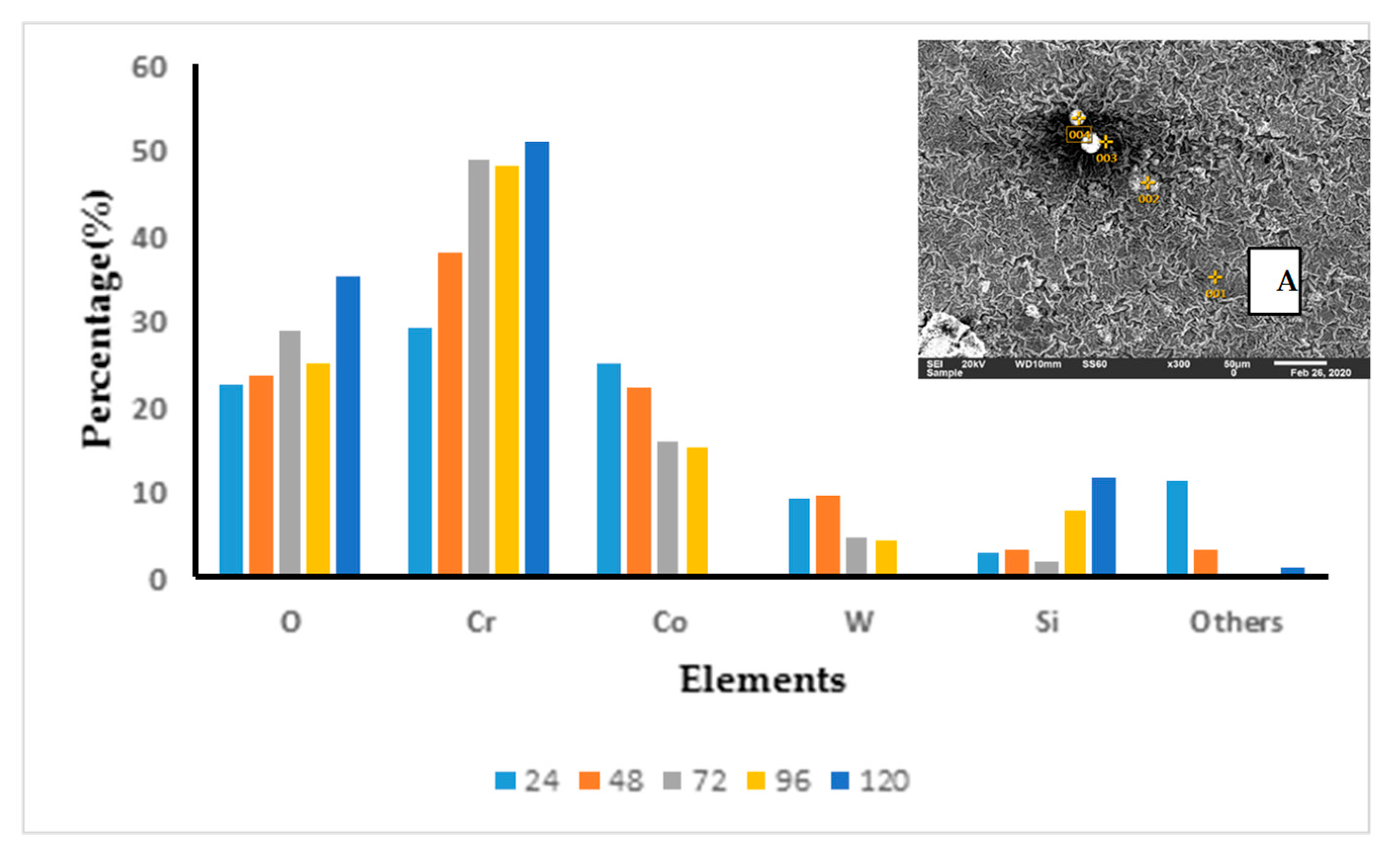
3.3.3. T-800/WC Surface Morphology and EDS
3.4. Oxidation Kinetics of the T-800/WC Coating and EN8
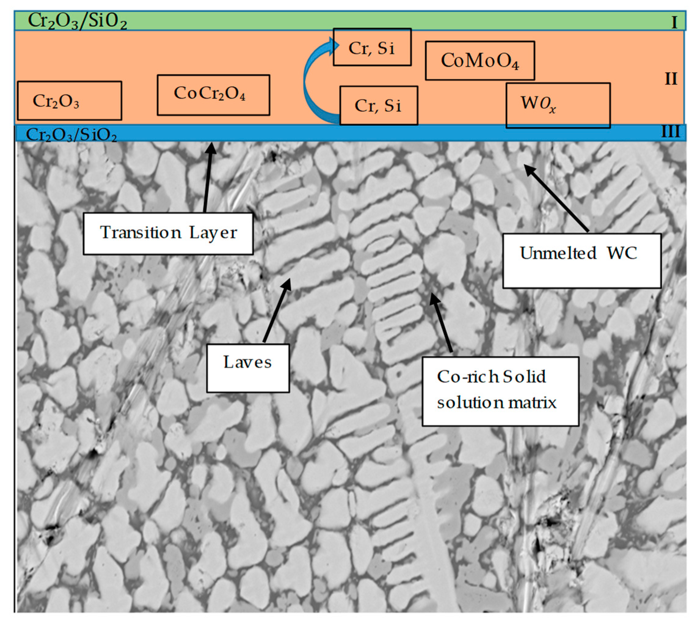
3.5. Mechanism of Elevated-Temperature Oxidation Resistance of the EN8 Substrate When Modified with the T-800/WC Coating
4. Conclusions
- The Kp constants for the coating were found to be approximately ten (10) times lower than for EN8, showing an increase in high-temperature resistance. The parabolic constant for EN8 was 6.72 × 10⁻¹² g2·cm−4·s−1, whilst that for the T-800 composite coating was 8.1 × 10⁻¹³ g2·cm−4·s−1. This was attributed to a stable chromium oxide (Cr2O3/SiO2) layer that formed on the surface of the coating, thereby preventing further oxidation, whilst the iron oxide film that formed on the EN8 substrate allowed the permeation of the oxygen ions into the oxide.
- The iron oxide (Fe2O3) film that developed on EN8 spalled, as evidenced by the cracking of oxide when the oxidation time was greater than 72 h, whilst the Cr2O3 film maintained its integrity at 120 h.
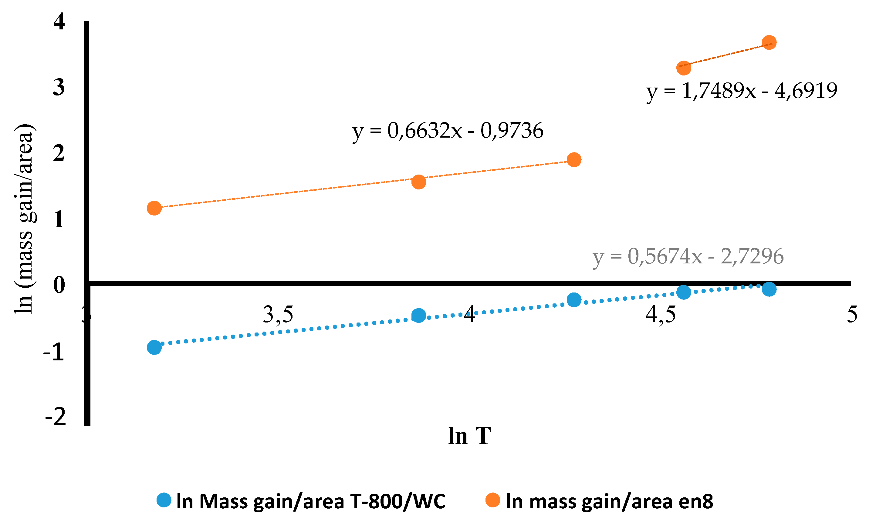
- A parabolic law was observed by the T-800 composite coating, whilst a paralinear law was reported for EN8 (as evidenced by n-values of 0.63 and 1.8, respectively) at 800 °C up to 120 h. It can thus be deduced that this coating can be used in turbine parts where temperatures are <800 °C.
Author Contributions
Funding
Institutional Review Board Statement
Informed Consent Statement
Data Availability Statement
Conflicts of Interest
Appendix A
Appendix B
References
- Khanna, A.S. High Temperature Corrosion; Indian Institute of Technology: Bombay, India, 2016. [Google Scholar] [CrossRef]
- Vasudev, H.; Thakur, L.; Bansal, A. High temperature oxidation and wear resistant bi-layer coating for turbocharger housing. In Methods for Film Synthesis and Coating Procedures; IntechOpen: London, UK, 2019. [Google Scholar]
- Feng, Y.; Feng, K.; Yao, C.; Li, Z.; Sun, J. High temperature oxidation and wear resistance of in situ synthesized (Ti3Al+ TiB)/Ti composites by laser cladding. Metall. Mater. Trans. A 2019, 50, 3414–3428. [Google Scholar] [CrossRef]
- Peng, J.; Fang, X.; Marx, V.; Jasnau, U.; Palm, M. Isothermal oxidation behavior of Tribaloy TM T400 and T800. NPJ Mater. Degrad. 2018, 2, 1–7. [Google Scholar] [CrossRef]
- Singh, S.; Goyal, D.K.; Kumar, P.; Bansal, A. Laser cladding technique for erosive wear applications: A review. Mater. Res. Express 2020, 7, 012007. [Google Scholar] [CrossRef]
- Vilar, R.; Almeida, A. Laser Surface Treatment of Biomedical Alloys. In Laser Surface Modification of Biomaterials; Woodhead Publishing: Sawston, UK, 2016; pp. 35–75. [Google Scholar] [CrossRef]
- Zhou, S.; Lei, J.; Dai, X.; Guo, J.; Gu, Z.; Pan, H. A comparative study of the structure and wear resistance of NiCrBSi/50 wt.% WC composite coatings by laser cladding and laser induction hybrid cladding. Int. J. Refract. Met. Hard Mater. 2016, 60, 17–27. [Google Scholar] [CrossRef]
- Farahmand, P. Experimental and Numerical Investigation on Cladding of Corrosion-Erosion Resistant Materials by a High Power Direct Diode Laser. Ph.D. Thesis, Southern Methodist University, Dallas, TX, USA, 2015. [Google Scholar]
- Zhang, K.; Wang, S.; Liu, W.; Long, R. Effects of substrate preheating on the thin-wall part built by laser metal deposition shaping. Appl. Surf. Sci. 2014, 317, 839–855. [Google Scholar] [CrossRef]
- Seger, R. Effect of Tungsten Carbides Properties of Overlay Welded WC/NiSiB Composite Coatings; MG 202X Examensarbete inom Maskinteknik Handledare. Master’s Thesis, KTH Royal Institute of Technology, Stockholm, Sweden, 2013. [Google Scholar]
- Amado, J.M.; Tobar, M.J.; Yáñez, A.; Amigó, V.; Candel, J.J. Crack free tungsten carbide reinforced Ni (Cr) layers obtained by laser cladding. Phys. Procedia 2011, 12, 338–344. [Google Scholar] [CrossRef] [Green Version]
- Pala, Z.; Bai, M.; Lukac, F.; Hussain, T. Laser clad and HVOF-sprayed stellite 6 coating in chlorine-rich environment with KCl at 700 °C. Oxid. Met. 2017, 88, 749–771. [Google Scholar] [CrossRef] [Green Version]
- Tuominen, J.; Vuoristo, P.; Mäntylä, T.; Ahmaniemi, S.; Vihinen, J.; Andersson, P.H. Corrosion behavior of HVOF-sprayed and Nd-YAG laser-remelted high-chromium, nickel-chromium coatings. J. Therm. Spray Technol. 2002, 11, 233–243. [Google Scholar] [CrossRef]
- Khanna, A.S.; Kumari, S.; Kanungo, S.; Gasser, A. Hard coatings based on thermal spray and laser cladding. Int. J. Refract. Met. Hard Mater. 2009, 27, 485–491. [Google Scholar] [CrossRef]
- Nascimento, E.D.; Amaral, L.M.; Ana Sofia, C.M.; D’Oliveira, A.S.C.M. Characterization and wear of oxides formed on CoCrMoSi alloy coatings. Surf. Coat. Technol. 2017, 332, 408–413. [Google Scholar] [CrossRef]
- Dudziak, T.; Datta, P.K.; Mayrhofer, P.H.; Rovere, F. High temperature oxidation resistance of CrAlYN-coated Ti45Al8Nb. Oxid. Met. 2011, 75, 359–376. [Google Scholar] [CrossRef]
- Pillis, M.F.; Correa, O.V.; Ramanathan, L.V. High temperature oxidation behavior of yttrium dioxide coated Fe-20Cr alloy. Mater. Res. 2016, 19, 611–617. [Google Scholar] [CrossRef] [Green Version]
- Pereira, J.C.; Zambrano, J.C.; Tobar, M.J.; Yañez, A.; Amigó, V. High temperature oxidation behavior of laser cladding MCrAlY coatings on austenitic stainless steel. Surf. Coat. Technol. 2015, 270, 243–248. [Google Scholar] [CrossRef]
- Zhuang, Q.; Zhang, P.; Li, M.; Yan, H.; Yu, Z.; Lu, Q. Microstructure, wear resistance and oxidation behavior of Ni-Ti-Si coatings fabricated on Ti6Al4V by laser cladding. Materials 2017, 10, 1248. [Google Scholar] [CrossRef] [PubMed] [Green Version]
- Buscail, H.; Rolland, R.; Riffard, F.; Issartel, C.; Perrier, S. Cobalt Based Alloy Oxidation at High Temperatures. Ceramika/Ceramics, Papers of the Commission on Ceramic Science, Polish Ceramic Bulletin Polish Academy of Science—Kraków Division, Polish Ceramic Society; Hal-01628823. 2013, pp. 1–11. Available online: https://hal.archives-ouvertes.fr/hal-01628823/document (accessed on 26 July 2020).
- Lysenko, E.N.; Surzhikov, A.P.; Zhuravkov, S.P.; Vlasov, V.A.; Pustovalov, A.V.; Yavorovsky, N.A. The oxidation kinetics study of ultrafine iron powders by thermogravimetric analysis. J. Anal. Calorim. 2014, 115, 1447–1452. [Google Scholar] [CrossRef]
- Yuduo, Z.; Zhigang, Y.; Chi, Z.; Hao, L. Effect of rhenium addition on isothermal oxidation behavior of tribaloy T-800 Alloy. Chin. J. Aeronaut. 2010, 23, 370–376. [Google Scholar] [CrossRef] [Green Version]
- Benitez Velez, S. Oxidation Kinetics and Mechanisms in HT-9 Ferritic/Martensitic Stainless Steel. Ph.D. Thesis, University of Florida, Gainesville, FL, USA, 2005. [Google Scholar]
- Hao, M.; Sun, B.; Wang, H. High-temperature oxidation behavior of Fe–1Cr–0.2Si Steel. Materials 2020, 13, 509. [Google Scholar] [CrossRef] [PubMed] [Green Version]
- Yuan, J.; Wu, X.; Wang, W.; Zhu, S.; Wang, F. Investigation on the enhanced oxidation of ferritic/martensitic steel P92 in pure steam. Materials 2014, 7, 2772–2783. [Google Scholar] [CrossRef] [PubMed] [Green Version]
- Wang, D.; Li, H.; Zheng, W. Oxidation behaviours of TA15 titanium alloy and TiBw reinforced TA15 matrix composites prepared by spark plasma sintering. J. Mater. Sci. Technol. 2020, 37, 46–54. [Google Scholar] [CrossRef]
- Mayrhofer, P.H.; Rachbauer, R.; Holec, D.; Rovere, F.; Schneider, J.M. Protective transition metal nitride coatings; Reference module in materials science and materials engineering. Compr. Mater. Process. 2014, 4, 355–388. [Google Scholar] [CrossRef]


| Chemical Composition | Co | Mo | Cr | Si | C | Ni | Fe | WC | Mn | P | S |
|---|---|---|---|---|---|---|---|---|---|---|---|
| Tribaloy T-800 | 46.7 (Bal.) | 28.5 | 18 | 3.5 | 0.8 | 1.5 | 1 | - | - | - | - |
| Tungsten Carbide (WC-86) | 10 | - | 4 | - | - | - | - | 86 | - | - | - |
| EN8 Stainless Steel | - | - | - | 0.25 | 0.4 | - | 98.52 (Bal.) | - | 0.8 | 0.015 | 0.015 |
| n Value | Kp Constant/( g2·cm−4·s−1) | |
|---|---|---|
| EN8 substrate material | 0.63 | |
| T-800/WC coating | 1.8 |
Publisher’s Note: MDPI stays neutral with regard to jurisdictional claims in published maps and institutional affiliations. |
© 2021 by the authors. Licensee MDPI, Basel, Switzerland. This article is an open access article distributed under the terms and conditions of the Creative Commons Attribution (CC BY) license (https://creativecommons.org/licenses/by/4.0/).
Share and Cite
Nyadongo, S.T.; Pityana, S.L.; Olakanmi, E.O. Isothermal Oxidation Performance of Laser Cladding Assisted with Preheat (LCAP) Tribaloy T-800 Composite Coatings Deposited on EN8. Coatings 2021, 11, 843. https://doi.org/10.3390/coatings11070843
Nyadongo ST, Pityana SL, Olakanmi EO. Isothermal Oxidation Performance of Laser Cladding Assisted with Preheat (LCAP) Tribaloy T-800 Composite Coatings Deposited on EN8. Coatings. 2021; 11(7):843. https://doi.org/10.3390/coatings11070843
Chicago/Turabian StyleNyadongo, Sipiwe Trinity, Sisa Lesley Pityana, and Eyitayo Olatunde Olakanmi. 2021. "Isothermal Oxidation Performance of Laser Cladding Assisted with Preheat (LCAP) Tribaloy T-800 Composite Coatings Deposited on EN8" Coatings 11, no. 7: 843. https://doi.org/10.3390/coatings11070843
APA StyleNyadongo, S. T., Pityana, S. L., & Olakanmi, E. O. (2021). Isothermal Oxidation Performance of Laser Cladding Assisted with Preheat (LCAP) Tribaloy T-800 Composite Coatings Deposited on EN8. Coatings, 11(7), 843. https://doi.org/10.3390/coatings11070843