Article

Effect of NiO Nanoparticle Addition on the Structural, Microstructural, Magnetic, Electrical, and Magneto-Transport Properties of La0.67Ca0.33MnO3 Nanocomposites

1
Superconductor and Thin Film Laboratory, Department of Physics, Faculty of Science, Universiti Putra Malaysia, UPM, Serdang 43400, Selangor Darul Ehsan, Malaysia
2
Department of Applied Physics, Faculty of Science and Technology, Universiti Kebangsaan Malaysia, UKM, Bangi 43600, Selangor Darul Ehsan, Malaysia
3
Shibaura Institute of Technology, 3 Chome-7-5 Toyosu, Koto, Tokyo 135-8548, Japan
*
Author to whom correspondence should be addressed.
Coatings 2021, 11(7), 835; https://doi.org/10.3390/coatings11070835
Submission received: 22 June 2021 / Revised: 9 July 2021 / Accepted: 9 July 2021 / Published: 11 July 2021
(This article belongs to the Special Issue New Advance in Superconductor and Superconducting Thin Films)

Abstract

:
Incorporation of the secondary oxide phase into the manganite composite capable of enhancing low-field magnetoresistance (LFMR) for viability in high-performance spintronic applications. Polycrystalline La0.67Ca0.33MnO3 (LCMO) was prepared via the sol–gel route in this study. The structural, microstructural, magnetic, electrical, and magneto-transport properties of (1−x) LCMO: x NiO, x = 0.00, 0.05, 0.10, 0.15 and 0.20 were investigated in detail. The X-ray diffraction (XRD) patterns showed the coexistence of LCMO and NiO in the composites. The microstructural analysis indicated the amount of NiO nanoparticles segregated at the grain boundaries or on the surface of LCMO grains increased with the increasing secondary phase content. LCMO and NiO still retained their individual magnetic phase as observed from AC susceptibility (ACS) measurement. This further confirmed that there is no interfacial diffusion reaction between these two compounds. The NiO nanoparticle acted as a barrier to charge transport and caused an increase in resistivity for composite samples. The residual resistivity due to the grain/domain boundary is responsible for the scattering mechanism in the metallic region as suggested by the theoretical model fitting, ρ ( T ) = ρ 0 + ρ 2 T 2 + ρ 4.5 T 4.5 . The magnetoresistance values of LCMO and its composites were found to increase monotonically with the decrease in temperature. Hence, the LFMR was observed. Nonetheless, the slight reduction of LFMR in composites was attributed to the thick boundary layer created by NiO and impaired the spin polarised tunnelling process.

1. Introduction

The hole-doped manganites with a general formula of RE1−xAxMnO3, where RE is a rare earth ion (RE = La, Nd, Pr) and A is a divalent alkaline earth metal ion (B = Ba, Sr, Ca) have attracted considerable research interest due to their intriguing properties. The correlation between spin, charge, orbital, and lattice degrees of freedom in manganites has been extensively studied [1,2,3]. Magnetoresistance effect is an important phenomenon to be utilised by magnetic field sensing elements in novel technological devices. It is described by the change of resistance when a conductor is placed under the influence of a magnetic field. The discovery of colossal magnetoresistance (CMR) on manganites has earned them a spot in spintronic technologies such as memory recording applications and magnetic field sensors [4]. Perovskite manganites exhibit CMR in the vicinity of metal-insulator transition and ferromagnetic–paramagnetic transition [5]. The electrical conduction and magnetism in manganites can be explained by the double exchange (DE) mechanism between pairs of Mn3+ and Mn4+ [6].
The CMR effects of perovskite manganites are grouped into two categories, namely intrinsic and extrinsic magnetoresistance, respectively [7]. The intrinsic magnetoresistance is only expressive at high saturation magnetic field about several teslas while the extrinsic magnetoresistance is significantly higher in low magnetic fields [8]. A high-efficiency magnetoresistive material should be able to respond at low magnetic fields for its viability in practical spintronic applications [9]. The extrinsic magnetoresistance is attributed to the spin polarised tunnelling, and it can be achieved by the natural or artificial grain boundaries in manganites [10,11]. Therefore, an introduction of the secondary oxide phase into the manganite system has been adopted by the scientific community as its capability to enhance low field magnetoresistance (LFMR). This approach is favoured by recent research works and has proven as an effective attempt to improve the LFMR as demonstrated by La0.8Sr0.2MnO3:NiO [12], La0.7Sr0.3MnO3: SrFe12O19 [13], La0.67Ca0.33MnO3: Sm2O3 [14], La0.7Ca0.2Sr0.1MnO3: MgO [15], La0.7Ca0.3MnO3: Al2O3 [16], La0.7Sr0.3MnO3: AZO [17] and La0.7Sr0.3MnO3: ZnO [18].
The understanding of the secondary oxide phase in the manganite composites development is important in designing high-performance spintronic applications. Nickel oxide (NiO) is an insulator with a high melting point and proved to be an excellent candidate as the secondary phase in manganite composites [19]. The NiO nanoparticle has successfully enhanced the LFMR of Pr0.67Sr0.33MnO3 composites prepared by solid-state reaction [20]. Additionally, Ning et al. incorporated NiO into the La0.7Ca0.3MnO3 nanocomposite thin films and significantly enhanced the LFMR over a broad temperature range by tuning the microstructures [21]. Eshraghi et al. described that the NiO doping influenced LFMR in La0.8Sr0.2MnO3:NiO composites [12]. From their study, the composites with high NiO content demonstrated the reduction in LFMR, originating from the substitution of Ni2+ with the Mn3+ and causing the magnetic dilution. Besides the concentration of the secondary phase, the spin polarised tunnelling responsible for LFMR could also be restricted by the nanosized parent compound, which was proposed in our previous work for LCMO: Al2O3 [22].
In this work, we prepared (1−x) LCMO: x NiO (x = 0.00, 0.05, 0.10, 0.15 and 0.20) by the sol–gel method. The effects of NiO nanoparticle addition on the structural, microstructural, magnetic, electrical, and magneto-transport properties were systematically examined. To the best of our knowledge, there is no up-to-date literature on the sol–gel synthesised LCMO:NiO nanocomposite. Hence, this work is important in providing a novel understanding of manganite composites.

2. Materials and Methods

(1−x) LCMO: x NiO composite samples were prepared by two stages, which are the synthesis of LCMO via sol–gel route and the addition of NiO nanoparticles. For the preparation of LCMO, the stoichiometric ratios of La(NO3)3·6H2O (Alfa Aesar, Heysham, UK; 99.99%), Ca(NO3)2·4H2O (Alfa Aesar, Heysham, UK; 99.98%) and Mn(NO3)2·4H2O (Merck, Darmstadt, Germany; ≥98.5%) were dissolved in an appropriate amount of distilled water under a constant stirring. Citric acid and ethylene glycol were later added to the precursor solution as a chelating agent and a dispersant (polymerization of metal ions), respectively. The mixed solution was left for 24 h and stirred constantly at 70 °C until it turned into a yellowish gel. The gel was further dried in an oven at 120 °C to remove the moisture. It was ground into fine powder in an agate mortar before being calcined at 500 °C for 5 h. Later, the powder was pre-sintered at 800 °C for 6 h to facilitate the formation of the LCMO phase. Next, the LCMO powder was added with different contents of NiO (Sigma Aldrich, St. Louis, MO, USA; 99.8%) nanoparticle (<50 nm) at x = 0.00, 0.05, 0.10, 0.15 and 0.20. These mixed powders were ground and pressed into pellets, then sintered at 800 °C for 2 h.
All samples were evaluated by an X-ray fluorescence spectrometer (XRF, Shimadzu EDX-720, Shimadzu Corporation, Kyoto, Japan) and energy-dispersive X-ray spectrometer (EDX, Max 20, Oxford Instruments, Abingdon, UK) to confirm the existence of a secondary phase (NiO) in the composites. The structural characterisation was carried out by an X-ray diffractometer (XRD, X’Pert Pro PW 3040, Malvern Panalytical, Malvern, UK) and Rietveld analysis was performed by HighScore Plus software. The surface morphologies and microstructures were observed by a field emission scanning electron microscope (FESEM, FEI Nova NanoSEM 230, Thermo Fisher Scientific, Waltham, MA, USA). AC susceptibility was measured by an AC susceptometer (ACS, CryoBIND T, CryoBIND, Zagreb, Croatia) in a magnetic field of 5 Oe at 219 Hz to determine the Curie temperature (TC). The temperature dependence of the resistivity and magneto-transport were assessed by standard four-point probe method using a Hall effect measurement system (HMS, Lakeshore 7604, Lake Shore Cryotronics, Westerville, OH, USA) from 80 K to 300 K.

3. Results and Discussion

X-ray diffraction patterns of the samples with different NiO contents are depicted in Figure 1a. Standard XRD peaks for LCMO and NiO are illustrated in red and blue vertical lines, respectively. All samples exhibited a strong orientation towards (121) plane direction. This is contributed by the dominant plane orientation of their parent compound (LCMO). Minor peaks corresponding to NiO in the composites were observed and the relative peak intensity is gradually increased with the increasing NiO content. All peaks were indexed with LCMO and NiO phases, indicating the coexistence of the two chemically separated phases. Figure 1b illustrates the Rietveld XRD pattern of the pure LCMO phase. The blue circle is the diffraction data obtained from the experiment, the black solid line is the calculated result, the green vertical line represents the diffraction peak position of the LCMO phase, the red solid line is the difference between the experimental value and the calculated value. The experimental data are considered to fit well with calculated data as given by the low residual values of RWP and χ2. The refinement parameters of (1−x) LCMO: x NiO (x = 0.00, 0.05, 0.10, 0.15 and 0.20) are summarised in Table 1. There is no significant change in the lattice constants (a, b, c, V) of LCMO composites. This implies that NiO is segregated on the surface of LCMO grains or at the grain boundaries [14,23]. The average crystallite size, D was calculated by Scherrer’s equation below and gathered in Table 2:
D = 0.9   λ β   cos θ
where β = βsampleβinstrumental, β is the line broadening at half of the maximum intensity (FWHM), λ is the X-ray wavelength (1.5406 Å) and θ is the position of the most intense diffraction peak. The calculated average crystallite size based on the (121) peak is found to be in the range of 35–39 nm as listed in Table 2. The results further confirmed that there is no reaction between NiO and LCMO as the changes in crystallite size are negligible.
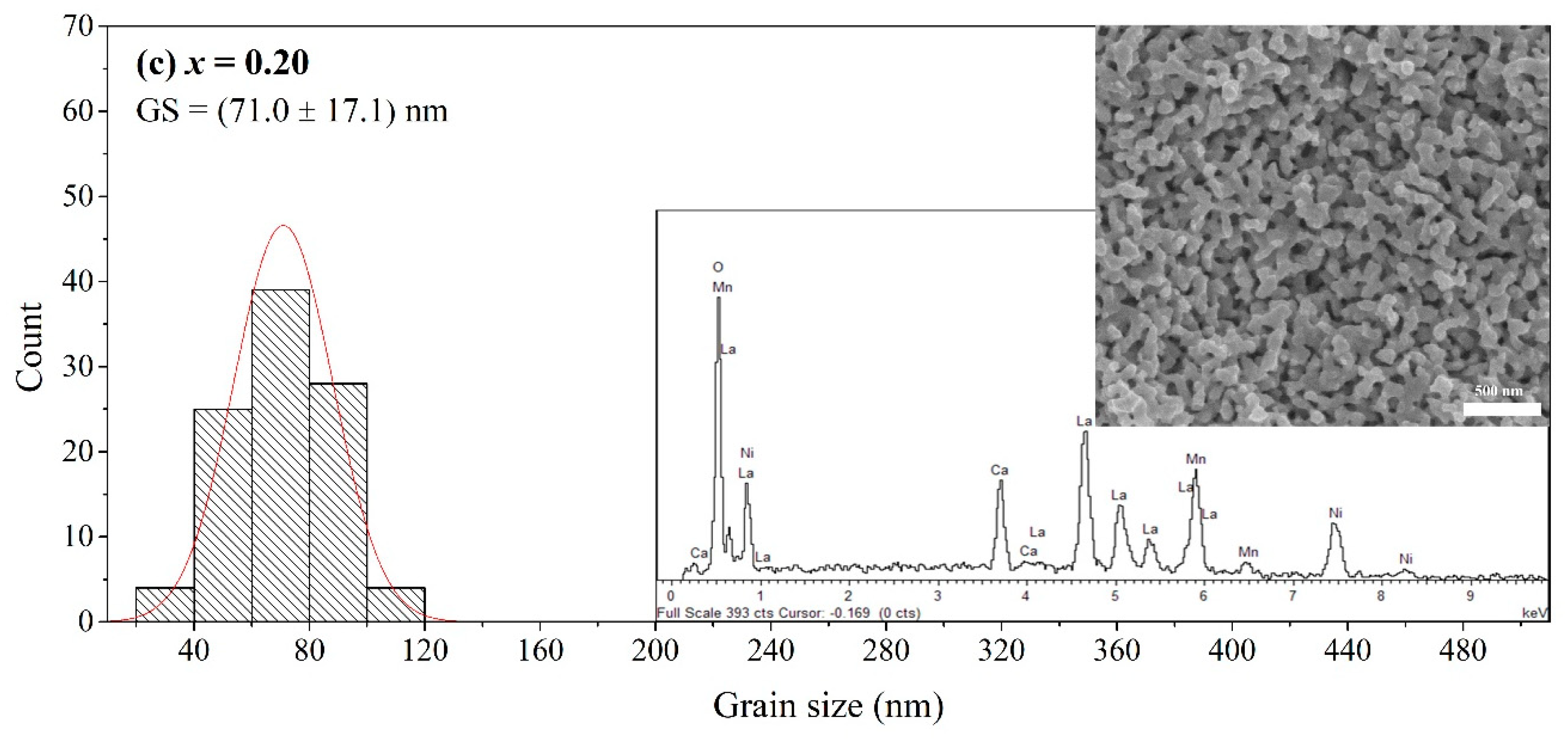
To analyse the addition of NiO nanoparticles on the microstructure of LCMO, the typical FESEM micrographs and grain size distributions of (1−x) LCMO: x NiO (x = 0.00, 0.10, 0.20) composites are shown in Figure 2a–c. Energy-dispersive X-ray (EDX) spectra are also included in Figure 2. The grain size distribution was depicted by 100 grains randomly picked from the FESEM micrographs. All samples were observed to compose with an irregular shape of grains, and it was found that the grain size of pure LCMO sample is in the range of 40–180 nm with 98.1 nm as the mean grain size. The average grain size of LCMO is ~3 times larger than its crystallite size, indicating the grain is consisting of several crystallites. The difference between grain and crystallite sizes is ascribed to the congregation or structure defects (vacancies, dislocations and stacking faults) of crystallite domains [24]. The grain size distribution is observed to skew to the left with the increasing NiO content. As a result, the mean grain size of samples reduced to ~70 nm with the addition of secondary phase (NiO). The reduction of average grain size in composites suggested that the NiO nanoparticle (<50 nm) was mainly segregated at the grain boundaries or on the surface of LCMO grains, which is in line with the XRD results. This also confirms the composite structure for the samples obtained in this work. The presence of La, Ca, Mn, O and Ni were confirmed by the EDX characterization and this supports the existence of NiO in the composites as demonstrated by the XRF results (not shown).
The magnetic properties of the samples were studied by the temperature dependence of AC susceptibility (ACS) measurement. All samples showed the ferromagnetic (FM)–paramagnetic (PM) transition as the temperature increases from 80 K to 330 K. The transition is demonstrated by a rapid drop of susceptibility until it reaches a minimum value (close to 0). The Tc can be identified from the inflection point of dχ’/dT versus T plot. Figure 3 shows the temperature dependence of the real part of AC susceptibility for LCMO:NiO composites. The TC of the pure LCMO was observed at 289 K and was denoted as TC1 in Table 2. This value is higher than the value reported by Xia et al. in La0.7Ca0.3MnO3 nanoparticle (268 K) [25]. The discrepancy can be attributed to the loss of long-range ferromagnetic ordering and the presence of magnetic disordered grain boundary layers in previously reported LCMO nanoparticles (<50 nm). The grain size of LCMO in this work is larger (98 nm), thus it has a higher value of TC [26,27]. The TC1 values recorded by the composite samples are in the range of 287–293 K. This indicates that the LCMO perovskite lattice remained intact, and no substitution occurred or formation of the new phase. The difference in TC of composites is insignificant by considering the FM–PM transition as an intrinsic and intragrain behaviour [28]. Nonetheless, there is an increase in the transition width and occurrence of TC2 for the LCMO:NiO composites. This can be ascribed to the presence of the antiferromagnetic material which is NiO nanoparticles at the grain boundaries and/or grain surfaces, where a similar behaviour was reported in La0.8Sr0.2MnO3:NiO composites [12]. Both TC1 and TC2 do not experience significant change with the increasing content of NiO. Therefore, we can deduce that LCMO and NiO still retain their individual magnetic phase in the composites and there is no interfacial reaction between these two phases.
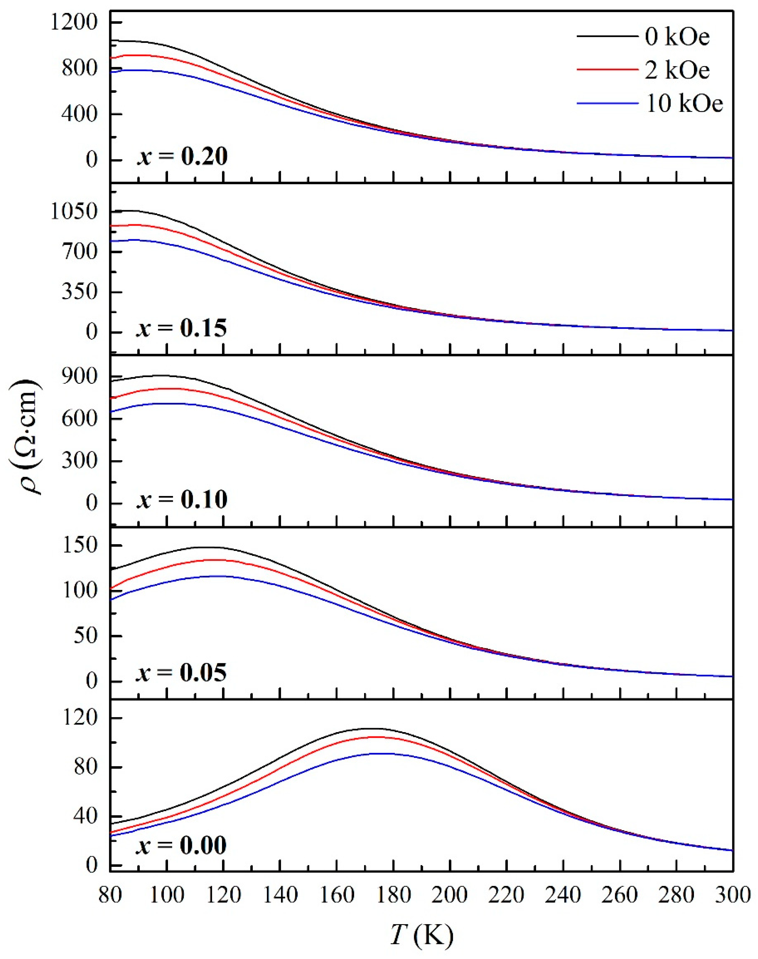
Figure 4 shows the temperature dependence of the resistivity at various fields (0 kOe, 2 kOe and 10 kOe) for the LCMO:NiO composites. It is observed that the resistivity of the samples increases with the concentration of NiO. This can be attributed to the increasing amount of NiO nanoparticles segregated at the grain boundaries or on the LCMO grain surface, and it contributes to the scattering enhancement near the grain boundaries. Most samples in this work (x = 0.00, 0.05 and 0.10) showed a distinct metal–insulator transition in the range of 80–180 K. The metal–insulator transition temperature (TMI) shifted to a higher temperature under the influence of a magnetic field. This effect is attributed to the alignment of localised spin in manganite and leads to the reduction in electron scattering, thus enhance the DE coupling in the metallic region [22,29]. Additionally, the TMI appeared to shift towards the lower temperature region with the increasing content of NiO in LCMO composites. The same behaviour was reported in our previous work for LCMO: Al2O3 composites [22]. This shift is caused by the segregation of NiO nanoparticles near the LCMO grains or grain boundaries of the composites. The NiO nanoparticle acted as a barrier to charge transport and caused an increase in the resistivity, as well as the dilution to the DE interaction [30]. The decrease of TMI values in composite samples also indicates that the extrinsic transport behaviour originates from the interface and grain boundary effects [11,31]. The transport behaviour of the composite can be explained by the parallel network of good and bad conduction channels, also known as the two-channel conduction model [13,18,32]. The charge transport in the pure LCMO sample is contributed by the direct contact between LCMO grains. In contrast, the presence of insulating NiO nanoparticles near the grain boundaries in composites results in the increase of resistivity and the shift of TMI towards the lower temperature region. Magnetic and electrical behaviours are important physical properties of manganite materials. From the literature, the values of TC and TMI are close to each other for bulk manganites [33]. Nevertheless, this differs for nanocrystalline samples as demonstrated by our work here. The difference between TC1 and TMI is given as ΔT and summarised in Table 2. The ΔT value is getting greater with the NiO content. This is because the electrical behaviour (TMI) is dependent on the microstructural properties such as grain size and grain boundary, while the magnetic behaviour (TC1) is a cumulative effect of intrinsic properties in manganites [24,34].
To gain insight into the different scattering mechanisms in the metallic region (T < TMI), the electrical resistivity data were fitted with the equation below [27,35,36]:
ρ ( T ) = ρ 0 + ρ 2 T 2 + ρ 4.5 T 4.5
where ρ 0 represents the grain/domain boundary effect, ρ 2 T 2 is due to the electron–electron scattering and ρ 4.5 T 4.5 is attributed to the electron–magnon scattering process in the ferromagnetic region. The experimental data were fitted to the theoretical models in ρT plots (not shown). The quality of fitting between them was accessed by the squared linear correlation coefficient (R2) and a good match between experimental results and theoretical models was obtained. The fitting parameters for all the samples are given in Table 3. It is observed that ρ 0 is greatest among all parameters. This implies that the residual resistivity due to the grain/domain boundary is primarily responsible for the conduction process in the metallic region. Interestingly, the ρ 0 has experienced a drastic increase compared to ρ 2 and ρ 4.5 as the NiO content increases in composite samples. This observation confirmed that the segregation of NiO at the grain/domain boundary and required electrons to tunnel through the NiO layer during the conduction process. Besides that, it can be seen that ρ 0 decreases with the application of the magnetic field. This might be attributed to the increase of domain size under the influence of the magnetic field, thus reducing the value of ρ 0 [5]. The polaron conduction is likely to responsible for the conduction in the semiconducting region (T > TMI) [37]. The small polaron hopping (SPH) model arising from the strong-phonon coupling due to the Jahn–Teller distortion is given by [38,39]:
ρ ( T ) = ρ a T   exp ( E a / K B T )
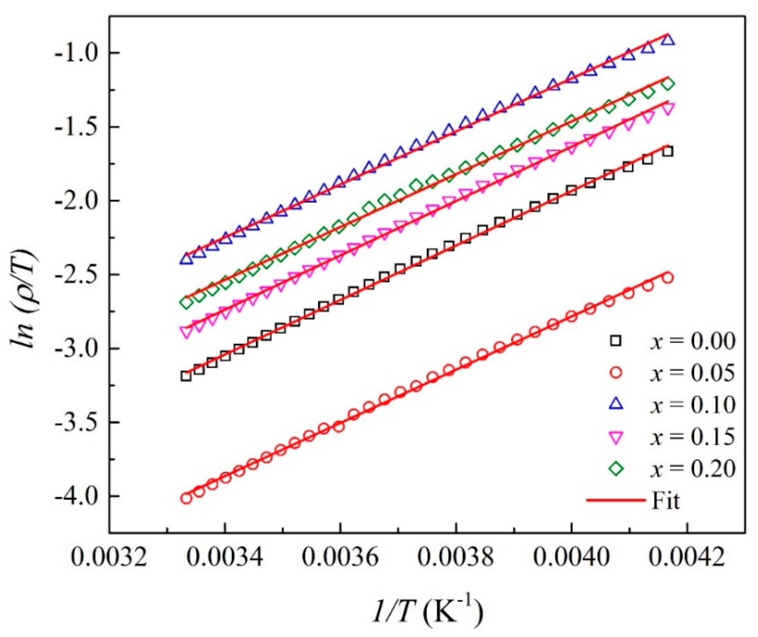
where ρ a is the temperature-independent coefficient, K B is Boltzmann’s constant and E a is the activation energy of the polaron. Figure 5 shows the graph of ln (ρ/T) against 1/T. The plot followed a linear relation at the high-temperature region and the obtained parameters are summarised in Table 3. The good fit between our data and the SPH model demonstrates that the conduction mechanism for the LCMO:NiO composites in the high-temperature region is mainly contributed by the hopping process of small polaron. As shown by the previous studies, the E a in SPH is related to the height of the phase boundaries [40,41]. It is interesting to point out that the E a values calculated for the LCMO:NiO composites in this work do not show a significant change with the increasing NiO content. This is contradicted with the previous works as the magnetic disorder in the secondary phase will dominate the conduction process and leads to a higher resistive phase boundary, so a higher E a is required for the higher concentration of the secondary phase [17,18]. However, the SPH model still accords well with the conduction mechanism in the high-temperature region. Hence, the scattering mechanism in the metallic region can be sufficiently described by the theoretical models as the resistivity data were well fitted with Equations (2) and (3).
Figure 6 illustrates the MR (%) as a function of external applied magnetic field (0–10 kOe) curves from 80–300 K for (1−x) LCMO: x NiO, x = 0.00, 0.05, 0.10, 0.15 and 0.20. The MR (%) is defined by Equation (4):
M R   ( % ) =   ρ H   ρ O ρ O × 100
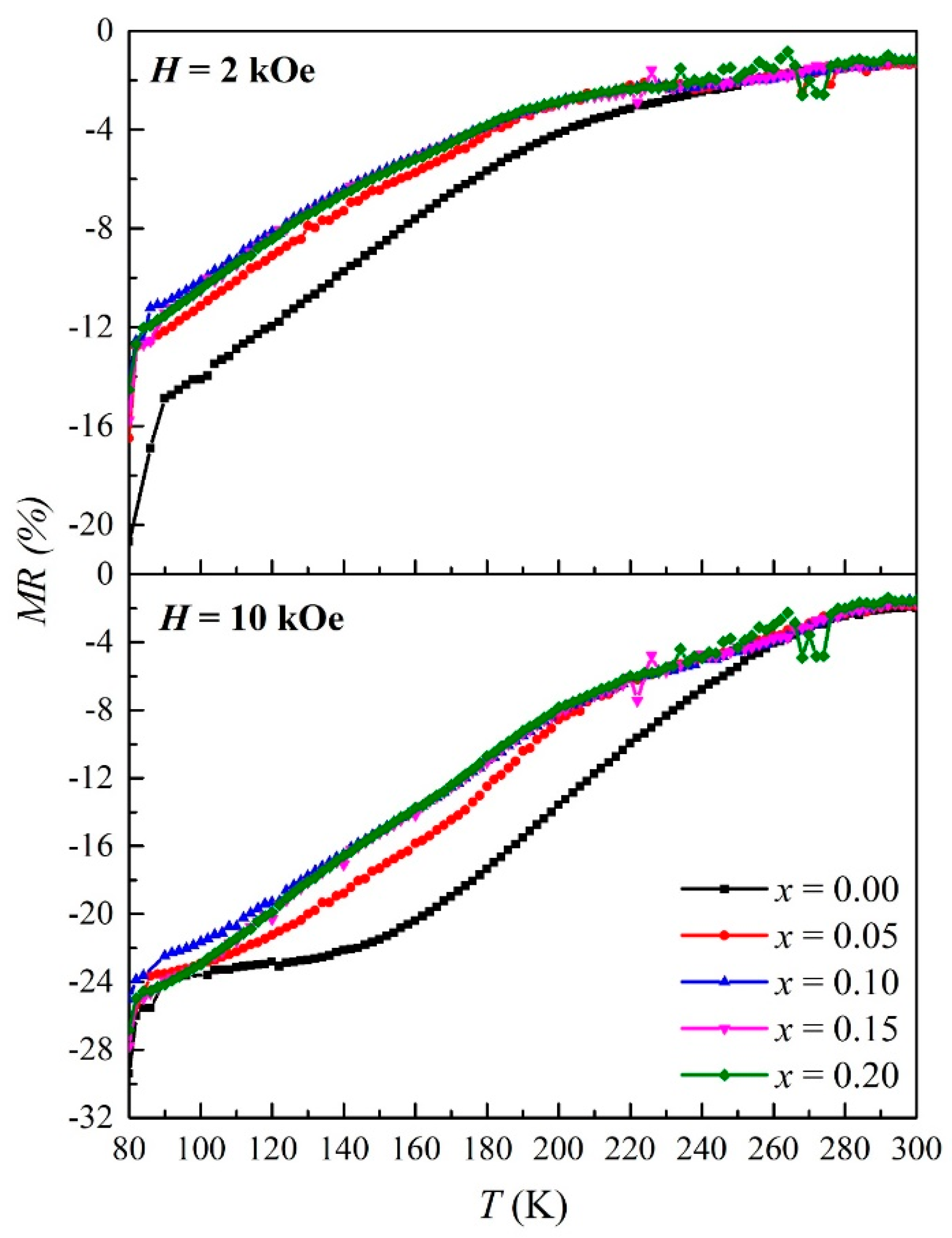
where ρ O and ρ H represent the resistivities without and with an applied magnetic field, respectively. The MR (%) curves display two distinct regions as the magnetic field increases. The first region (H ≤ 2 kOe), better known as LFMR, exhibits a steeper slope in contrast with another part of the curve. The LFMR effect can be attributed to the spin polarised tunnelling across the grain boundaries [11]. The disorder spins in manganite will align when the magnetic field starts to apply, and this causes a drastic drop in resistivity at the low field region due to the electron hopping enhancement. On the other hand, the MR (%) increases linearly with the applied magnetic field with a reduced slope in the high field region above 2 kOe. The high field magnetoresistance can be explained by the slow rotation of the grain core and the reduction in the probability of domain-wall scattering with the application of a magnetic field [42,43]. The pure LCMO sample obtained the highest MR (%) in this work, which is 29.41% at 80 K (10 kOe). To investigate the variation of magnetic fields on the MR (%) of LCMO:NiO composites, plots of MR (%) against T at 2 kOe and 10 kOe are presented in Figure 7. It is observed that LFMR (2 kOe) is more pronounced at low temperatures by showing a higher value as the temperature decreases. The intrinsic MR (%) plot (10 kOe) can be explained by the suppression from spin fluctuations, where the spins are aligned parallel to the magnetic field and exhibit a high MR (%) value near the TMI or TC. As displayed by MR (%) curves at 2 kOe, the MR (%) of LCMO and its composites increases monotonically with the decrease in temperature and the LFMR was observed. However, the LFMR becomes narrower above 80 K as the NiO content increases and there is no improvement of LFMR contributed by the composites compared with the pure LCMO. In fact, the LFMR originates from the spin polarised tunnelling near the grain boundaries, and grain boundaries can be enhanced through the grain size reduction or the addition of a secondary phase by creating the artificial grain boundaries. The thickness of the grain boundaries created by NiO in this work may exceed the spin memory length and too thick for spin-preserving electron tunnelling [17,44]. As a result, the spin-dependent tunnelling process is impaired and induces a decrease in LFMR in composite samples. In addition, the thickness of grain boundaries could also be the cause of the fluctuation that happened at MR (%) curves at the high-temperature region, as well as the inconsistency of the E a calculated by SPH fitting in this work compared to previous studies.

4. Conclusions

The LCMO:NiO composites were successfully synthesised by the sol–gel method. Their structural, microstructural, magnetic, electrical, and magneto-transport properties were systematically studied in this work. The XRD analysis showed that LCMO crystallised into orthorhombic (Pnma) and NiO into cubic (Fm-3m) structures. Both phases coexisted in the composite samples. As NiO content increases, the changes in the lattice constants of composites are insignificant, indicating that NiO was segregated outside the LCMO grains and at the grain boundaries. From microstructural characterisation, the average grain size of composites reduced to ~70 nm with the addition of NiO and confirmed the composite structure of LCMO:NiO. The temperature dependence of AC susceptibility showed double transition for composite samples due to the presence of the antiferromagnetic material (NiO) at the grain boundaries or grain surfaces. The NiO nanoparticle acted as a barrier to charge transport in composites and shifted TMI to lower temperatures. From the theoretical model fitting in the metallic region, the residual resistivity due to the grain/domain boundary is mainly responsible for the conduction process. The LFMR was observed and it is more pronounced at low temperatures. However, there is no improvement of LFMR contributed by the composites compared with the pure LCMO. The concentration of NiO used in this work may create the grain boundary which is larger than the spin memory length and hampered the electron tunnelling process. The findings presented are able to provide some insights into the composite design development especially in the control of secondary phase concentration.

Author Contributions

Conceptualization, L.N.L. and K.P.L.; methodology, L.N.L., S.Y.C. and K.P.L.; validation, L.N.L., S.Y.C., X.T.H., Y.J.W. and A.N.I.; formal analysis, L.N.L., S.Y.C. and K.P.L.; investigation, L.N.L., S.Y.C., X.T.H., Y.J.W. and A.N.I.; resources, K.P.L., M.M.A.K., S.K.C., N.B.I., M.M. (Muralidhar Miryala), M.M. (Masato Murakami) and A.H.S.; writing—original draft preparation, L.N.L.; writing—review and editing, L.N.L. and K.P.L.; visualization, L.N.L. and K.P.L.; supervision, K.P.L., M.M.A.K., S.K.C., N.B.I., M.M. (Muralidhar Miryala), M.M. (Masato Murakami) and A.H.S.; project administration, K.P.L., M.M.A.K., S.K.C. and A.H.S.; funding acquisition, K.P.L., M.M.A.K., S.K.C., N.B.I. and A.H.S. All authors have read and agreed to the published version of the manuscript.

Funding

This research was fully funded and supported by the Ministry of Higher Education, Malaysia (MOHE), through the Fundamental Research Grant Scheme (FRGS/1/2019/STG07/UPM/02/4) and a Universiti Putra Malaysia (UPM) research grant (GP-IPS/2018/9663900).

Institutional Review Board Statement

Not applicable.

Informed Consent Statement

Not applicable.

Data Availability Statement

The data that support the findings of this study are openly available in Zenodo at http://doi.org/10.5281/zenodo.5089602 (accessed on 10 July 2021).

Acknowledgments

The authors are grateful to the support staff who assisted in the characterisation measurements and for the facilities provided by UPM. L.N. is thankful to the Shibaura Institute of Technology, SIT as the host of aPBL under the Sakura Science Plan and facilitated some of the sample characterisation in this work.

Conflicts of Interest

The authors declare no conflict of interest.

References

  1. Mishra, D.; Roul, B.; Singh, S.; Srinivasu, V. Possible observation of Griffith phase over large temperature range in plasma sintered La0.67Ca0.33MnO3. J. Magn. Magn. Mater. 2018, 448, 287–291. [Google Scholar] [CrossRef]
  2. Panchal, G.; Choudhary, R.J.; Phase, D.M. Magnetic properties of La0.7Sr0.3MnO3 film on ferroelectric BaTiO3 substrate. J. Magn. Magn. Mater. 2018, 448, 262–265. [Google Scholar] [CrossRef]
  3. Gong, J.; Zheng, D.; Li, D.; Jin, C.; Bai, H. Lattice distortion modified anisotropic magnetoresistance in epitaxial La0.67Sr0.33MnO3 thin films. J. Alloy. Compd. 2018, 735, 1152–1157. [Google Scholar] [CrossRef]
  4. Xia, W.; Pei, Z.; Leng, K.; Zhu, X. Research progress in rare earth-doped perovskite manganite oxide nanostructures. Nanoscale Res. Lett. 2020, 15, 1–55. [Google Scholar] [CrossRef] [PubMed] [Green Version]
  5. Ng, S.; Lim, K.; Halim, S.; Jumiah, H. Grain size effect on the electrical and magneto-transport properties of nanosized Pr0.67Sr0.33MnO3. Results Phys. 2018, 9, 1192–1200. [Google Scholar] [CrossRef]
  6. Zener, C. Interaction between the d-shells in the transition metals. II. Ferromagnetic compounds of manganese with perovskite structure. Phys. Rev. 1951, 82, 403. [Google Scholar] [CrossRef]
  7. Tang, T.; Tien, C.; Hou, B. Low-field magnetoresistance of Ag-substituted perovskite-type manganites. Phys. B Condens. Matter 2008, 403, 2111–2115. [Google Scholar] [CrossRef]
  8. Nagaev, E.L. Colossal-magnetoresistance materials: Manganites and conventional ferromagnetic semiconductors. Phys. Rep. 2001, 346, 387–531. [Google Scholar] [CrossRef]
  9. Sadhu, A.; Bhattacharyya, S. Enhanced low-field magnetoresistance in La0.71Sr0.29MnO3 nanoparticles synthesized by the nonaqueous sol–gel route. Chem. Mater. 2014, 26, 1702–1710. [Google Scholar] [CrossRef]
  10. Phong, P.T.; Khiem, N.V.; Dai, N.V.; Manh, D.H.; Hong, L.V.; Phuc, N.X. Influence of Al2O3 on low-field spin-polarized tunneling magnetoresistance of (1−x) La0.7Ca0.3MnO3+x Al2O3 composites. Mater. Lett. 2009, 63, 353–356. [Google Scholar] [CrossRef]
  11. Hwang, H.; Cheong, S.; Ong, N.; Batlogg, a.B. Spin-polarized intergrain tunneling in La2/3Sr1/3MnO3. Phys. Rev. Lett. 1996, 77, 2041. [Google Scholar] [CrossRef]
  12. Eshraghi, M.; Salamati, H.; Kameli, P. The effect of NiO doping on the structure, magnetic and magnetotransport properties of La0.8Sr0.2MnO3 composite. J. Alloy. Compd. 2007, 437, 22–26. [Google Scholar] [CrossRef]
  13. Zi, Z.; Fu, Y.; Liu, Q.; Dai, J.; Sun, Y. Enhanced low-field magnetoresistance in LSMO/SFO composite system. J. Magn. Magn. Mater. 2012, 324, 1117–1121. [Google Scholar] [CrossRef]
  14. Li, J.; Chen, Q.; Yang, S.a.; Yan, K.; Zhang, H.; Liu, X. Electrical transport properties and enhanced broad-temperature-range low field magnetoresistance in LCMO ceramics by Sm2O3 adding. J. Alloy. Compd. 2019, 790, 240–247. [Google Scholar] [CrossRef]
  15. Dar, M.A.; Malla, M.; Solanki, J.; Varshney, D. Enhanced low field magnetoresistance in La0.7Ca0.2Sr0.1MnO3-MgO composites. In Proceedings of the AIP Conference Proceedings; American Institute of Physics: College Park, MA, USA, 2017; p. 140013. [Google Scholar]
  16. Thanh, T.D.; Phong, P.T.; Dai, N.V.; Manh, D.H.; Khiem, N.V.; Hong, L.V.; Phuc, N.X. Magneto-transport and magnetic properties of (1–x)La0.7Ca0.3MnO3+xAl2O3 composites. J. Magn. Magn. Mater. 2011, 323, 179–184. [Google Scholar] [CrossRef]
  17. Wang, C.B.; Liu, H.X.; Wu, L.; Shen, Q.; Zhang, L.M. Enhanced low-field magnetoresistance in LSMO/AZO composites prepared by plasma activated sintering. Ceram. Int. 2018, 44, 18048–18053. [Google Scholar] [CrossRef]
  18. Navin, K.; Kurchania, R. Structural, magnetic and transport properties of the La0.7Sr0.3MnO3-ZnO nanocomposites. J. Magn. Magn. Mater. 2018, 448, 228–235. [Google Scholar] [CrossRef]
  19. Gaur, A.; Varma, G.D. Magnetoresistance behaviour of La0.7Sr0.3MnO3/NiO composites. Solid State Commun. 2006, 139, 310–314. [Google Scholar] [CrossRef]
  20. Lim, K.P.; Shaari, A.H.; Chen, S.K.; Hassan, J.; Ng, S.W.; Wan Jusoh, W.N.W.; Fadin, N. Electrical Transport Properties and Magnetoresistance of Pr0.67Sr0.33MnO3-NiO Composites. In Proceedings of the Solid State Phenomena; Trans Tech Publications Ltd.: Bäch SZ, Switzerland, 2017; pp. 292–296. [Google Scholar]
  21. Ning, X.; Wang, Z.; Zhang, Z. Controllable self-assembled microstructures of La0.7Ca0.3MnO3: NiO nanocomposite thin films and their tunable functional properties. Adv. Mater. Interfaces 2015, 2, 1500302. [Google Scholar] [CrossRef]
  22. Lau, L.N.; Lim, K.P.; Ngai, L.M.; Ishak, A.N.; Kechik, M.M.A.; Chen, S.K.; Ibrahim, N.B.; Shaari, A.H. Influence of Al2O3 on the low-field magnetoresistance of sol–gel grown La0.67Ca0.33MnO3: Al2O3 nanocomposites. Appl. Phys. A 2020, 126, 1–7. [Google Scholar] [CrossRef]
  23. Amri, N.; Nasri, M.; Triki, M.; Dhahri, E. Synthesis and characterization of (1−x)(La0.6Ca0.4MnO3)/x (Sb2O3) ceramic composites. Phase Transit. 2019, 92, 52–64. [Google Scholar] [CrossRef]
  24. Lim, K.P.; Ng, S.W.; Lau, L.N.; Kechik, M.M.A.; Chen, S.K.; Halim, S.A. Unusual electrical behaviour in sol–gel-synthesised PKMO nano-sized manganite. Appl. Phys. A 2019, 125, 745. [Google Scholar] [CrossRef]
  25. Xia, W.; Li, L.; Wu, H.; Xue, P.; Zhu, X. Structural, morphological, and magnetic properties of sol-gel derived La0.7Ca0.3MnO3 manganite nanoparticles. Ceram. Int. 2017, 43, 3274–3283. [Google Scholar] [CrossRef]
  26. Arun, B.; Akshay, V.R.; Chandrasekhar, K.D.; Mutta, G.R.; Vasundhara, M. Comparison of structural, magnetic and electrical transport behavior in bulk and nanocrystalline Nd-lacunar Nd0.67Sr0.33MnO3 manganites. J. Magn. Magn. Mater. 2019, 472, 74–85. [Google Scholar] [CrossRef]
  27. Navin, K.; Kurchania, R. The effect of particle size on structural, magnetic and transport properties of La0.7Sr0.3MnO3 nanoparticles. Ceram. Int. 2018, 44, 4973–4980. [Google Scholar] [CrossRef]
  28. Chand, U.; Yadav, K.; Gaur, A.; Varma, G. Magnetic and Magnetotransport Properties of (Pr0.7Sr0.3MnO3)1−x/NiOx Composites. In Proceedings of the AIP Conference Proceedings; American Institute of Physics: College Park, MA, USA, 2011; pp. 1263–1264. [Google Scholar]
  29. Venkataiah, G.; Venugopal Reddy, P. Electrical behavior of sol–gel prepared Nd0.67Sr0.33MnO3 manganite system. J. Magn. Magn. Mater. 2005, 285, 343–352. [Google Scholar] [CrossRef]
  30. Staruch, M.; Gao, H.; Gao, P.-X.; Jain, M. Low-field magnetoresistance in La0.67Sr0.33MnO3:ZnO composite film. Adv. Funct. Mater. 2012, 22, 3591–3595. [Google Scholar] [CrossRef]
  31. Wang, T.; Chen, X.; Wang, F.; Shi, W. Low-field magnetoresistance in La0.7Sr0.3MnO3/CuCrO2 composites. Phys. B Condens. Matter 2010, 405, 3088–3091. [Google Scholar] [CrossRef]
  32. De Andres, A.; Garcia-Hernandez, M.; Martinez, J. Conduction channels and magnetoresistance in polycrystalline manganites. Phys. Rev. B 1999, 60, 7328. [Google Scholar] [CrossRef]
  33. Lau, L.N.; Lim, K.P.; Ishak, A.N.; Awang Kechik, M.M.; Chen, S.K.; Ibrahim, N.B.y.; Miryala, M.; Murakami, M.; Shaari, A.H. The physical properties of submicron and nano-grained La0.7Sr0.3MnO3 and Nd0.7Sr0.3MnO3 synthesised by sol–gel and solid-state reaction methods. Coatings 2021, 11, 361. [Google Scholar] [CrossRef]
  34. Thombare, B.; Dusane, P.; Kekade, S.; Salunkhe, A.; Choudhary, R.J.; Phase, D.M.; Devan, R.S.; Patil, S.I. Influence of nano-dimensionality on magnetotransport, magnetic and electrical properties of Nd1−xSrxMnO3−δ (0.3 ≤ x ≤ 0.7). J. Alloy. Compd. 2019, 770, 257–266. [Google Scholar] [CrossRef]
  35. Li, Y.; Zhang, H.; Chen, Q.; Li, D.; Li, Z.; Zhang, Y. Effects of A-site cationic radius and cationic disorder on the electromagnetic properties of La0.7Ca0.3MnO3 ceramic with added Sr, Pb, and Ba. Ceram. Int. 2018, 44, 5378–5384. [Google Scholar] [CrossRef]
  36. Mohamed, H. Influence of sodium doping on the electrical and magnetic properties of La0.90Li0.10MnO3 manganites. J. Magn. Magn. Mater. 2017, 424, 44–52. [Google Scholar] [CrossRef]
  37. Wang, C.B.; Shen, Y.J.; Zhu, Y.X.; Zhang, L.M. Transport properties of La1−xSrxMnO3 ceramics above metal–insulator transition temperature. Phys. B Condens. Matter 2015, 461, 57–60. [Google Scholar] [CrossRef]
  38. Varshney, D.; Dodiya, N. Electrical resistivity of alkali metal doped manganites LaxAyMnwO3 (A = Na, K, Rb): Role of electron–phonon, electron–electron and electron–magnon interactions. Curr. Appl. Phys. 2013, 13, 1188–1198. [Google Scholar] [CrossRef]
  39. Ehsani, M.H.; Kameli, P.; Ghazi, M.E. Influence of grain size on the electrical properties of the double-layered LaSr2Mn2O7 manganite. J. Phys. Chem. Solids 2012, 73, 744–750. [Google Scholar] [CrossRef]
  40. De Teresa, J.; Ibarra, M.; Blasco, J.; Garcia, J.; Marquina, C.; Algarabel, P.; Arnold, Z.; Kamenev, K.; Ritter, C.; Von Helmolt, R. Spontaneous behavior and magnetic field and pressure effects on La2/3Ca1/3MnO3 perovskite. Phys. Rev. B 1996, 54, 1187. [Google Scholar] [CrossRef]
  41. Ning, X.; Wang, Z.; Zhang, Z. Large, Temperature-tunable low-field magnetoresistance in La0.7Sr0.3MnO3: NiO nanocomposite films modulated by microstructures. Adv. Funct. Mater. 2014, 24, 5393–5401. [Google Scholar] [CrossRef]
  42. Zhou, Y.; Zhu, X.; Li, S. Structure, magnetic, electrical transport and magnetoresistance properties of La0.67Sr0.33Mn1−xFexO3 (x = 0–0.15) doped manganite coatings. Ceram. Int. 2017, 43, 3679–3687. [Google Scholar] [CrossRef]
  43. Modi, A.; Bhat, M.A.; Pandey, D.K.; Tarachand; Bhattacharya, S.; Gaur, N.K.; Okram, G.S. Structural, magnetotransport and thermal properties of Sm substituted La0.7−xSmxBa0.3MnO3 (0 ≤ x ≤ 0.2) manganites. J. Magn. Magn. Mater. 2017, 424, 459–466. [Google Scholar] [CrossRef]
  44. Xiong, C.; Huang, Q.; Xiong, Y.; Ren, Z.; Wei, L.; Zhu, Y.; Li, X.; Sun, C. Electro-magnetic transport behavior of La0.7Ca0.3MnO3/SnO2 composites. Mater. Res. Bull. 2008, 43, 2048–2054. [Google Scholar] [CrossRef]
Figure 1. (a) XRD patterns of LCMO:NiO composites. (b) Rietveld refinement of LCMO.
Coatings 11 00835 g001
Figure 2. Grain size distribution histograms, FESEM micrographs and EDX spectra of (a) x = 0.00, (b) x = 0.10 and (c) x = 0.20.
Coatings 11 00835 g002aCoatings 11 00835 g002b
Figure 3. Temperature dependence of AC susceptibility for LCMO:NiO composites.
Coatings 11 00835 g003
Figure 4. Temperature dependence of the resistivity at various fields for the pure LCMO and its composites.
Coatings 11 00835 g004
Figure 5. Fitting of resistivity curves of (1−x) LCMO: x NiO composites by Equation (3).
Coatings 11 00835 g005
Figure 6. MR (%) as a function of external applied magnetic field curves from 80–300 K for (1−x) LCMO: x NiO, x = 0.00, 0.05, 0.10, 0.15 and 0.20.
Coatings 11 00835 g006
Figure 7. Temperature dependence of MR (%) for LCMO:NiO composites at 2 kOe and 10 kOe.
Coatings 11 00835 g007
Table 1. Rietveld refinement data of pure LCMO and LCMO:NiO composites.
Sample LCMO
Ref. code98-006-5295
Structure typeOrthorhombic
Space groupPnma (62)
NiO content, x0.000.050.100.150.20
a (Å)5.4545.454 5.4535.4525.454
b (Å)7.710 7.704 7.7177.7057.706
c (Å)5.462 5.473 5.4585.4675.473
V3)229.688229.975229.676229.684230.334
Mn1-O1 (Å)1.930 (19)1.932(14)1.929 (22)1.931 (17)1.932 (18)
Mn1-O1 (Å)1.974 (19)1.977 (14)1.973 (23)1.975 (17)1.977 (19)
Mn1-O2 (Å)1.954 (13)1.952 (5)1.955 (19)1.953 (8)1.953 (8)
Mn1-O1-Mn1 (°)162.6 (3)162.6 (4)162.5 (6)162.6 (6)162.58 (6)
Mn1-O2-Mn1 (°)161.2 (7)161.1 (9)161.2 (7)161.2 (7)161.1 (7)
REXP (%)4.6254.1783.8433.7573.511
RP (%)3.5783.3243.0643.0032.853
RWP (%)4.6284.3173.9173.8183.546
Goodness of fit, χ21.0011.0681.0391.0321.020
SampleNiO
Ref. code98-000-8168
Structure typeCubic
Space groupFm-3m (225)
a (Å)-4.1794.1774.1774.179
b (Å)-4.1794.1774.1774.179
c (Å)-4.1794.1774.1774.179
V3)-72.9772.8672.8672.96
Table 2. The D, TMI, and MR (%) at 80 K for sample x = 0.00, 0.05, 0.10, 0.15 and 0.20.
xD (nm)TC1 (K)TC2 (K)TMI (K)ΔT (K)MR (%) at 80 K
2 kOe10 kOe
0.0035.8289-17211720.7029.41
0.0535.929317911617716.4826.70
0.1037.52871739818914.0925.04
0.1538.7291174<80-15.7627.84
0.2035.3292175<80-14.5326.83
Table 3. Parameters obtained corresponding to the best fit of the experimental data based on Equations (2) and (3) for (1−x) LCMO: x NiO (x = 0.00, 0.05, 0.10, 0.15 and 0.20).
NiO Content, xH (kOe) ρ ( T ) = ρ 0 + ρ 2 T 2 + ρ 4.5 T 4.5 ρ ( T ) = ρ a T   exp ( E a / K B T )
ρ 0
(Ω cm)
ρ 2
(Ω cm K−2)
ρ 4.5
(Ω cm K−4.5)
R2Ea (meV)R2
0.000−0.1310.0047−9.81 × 10−100.9981.5890.999
10−1.3730.0037−9.00 × 10−100.998--
0.05050.8400.0133−4.20 × 10−80.9991.5520.998
1037.5760.0102−3.01 × 10−80.999--
0.100607.8120.0534−2.40 × 10−70.9991.5450.998
10250.1090.0845−3.87 × 10−70.997--
0.150----1.5850.999
10------
0.200----1.5400.997
10------
Publisher’s Note: MDPI stays neutral with regard to jurisdictional claims in published maps and institutional affiliations.