Structure and Properties of DLC Films Deposited on Mg Alloy at Different C2H2 Flows of Magnetron Sputtering Process


Abstract
:1. Introduction
2. Materials and Methods
3. Results and Discussion
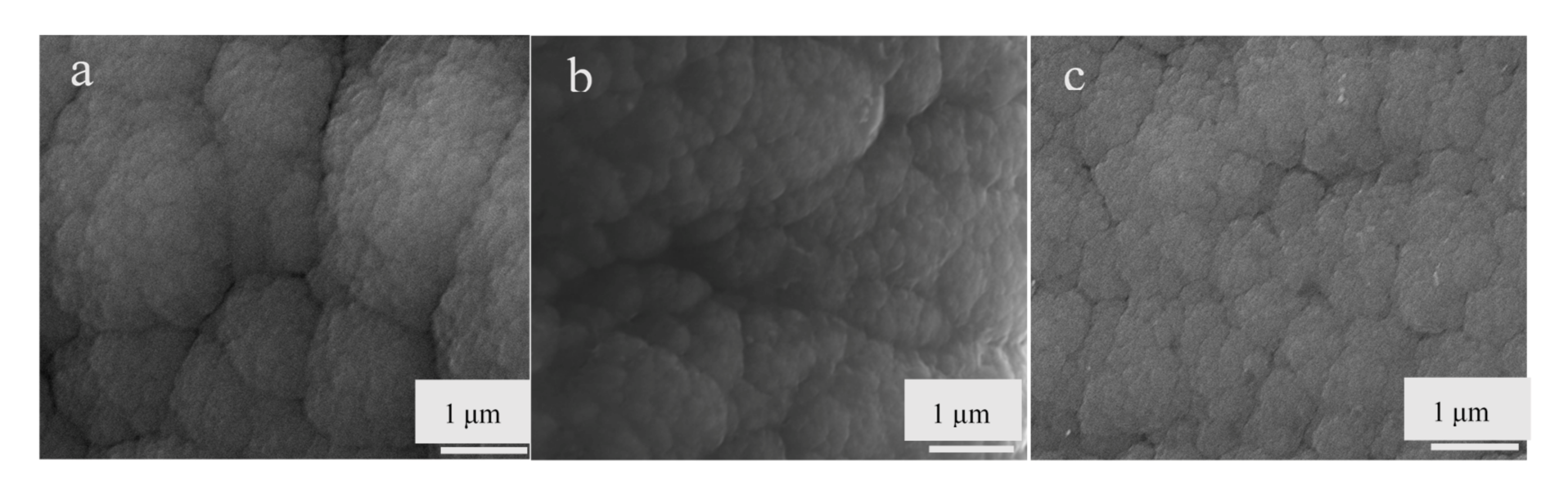
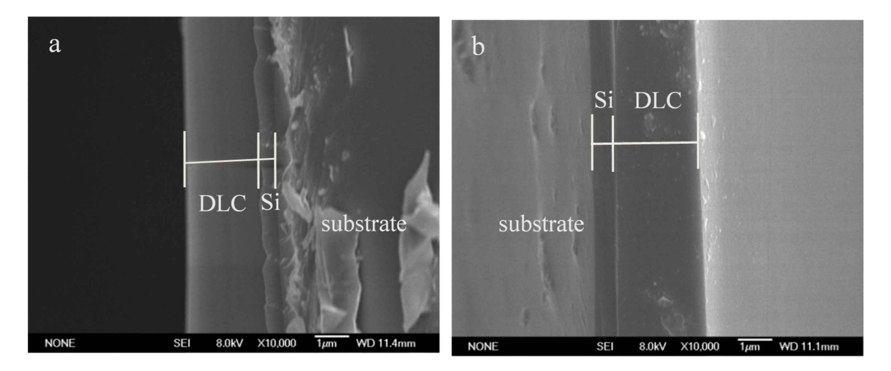
3.1. Morphology
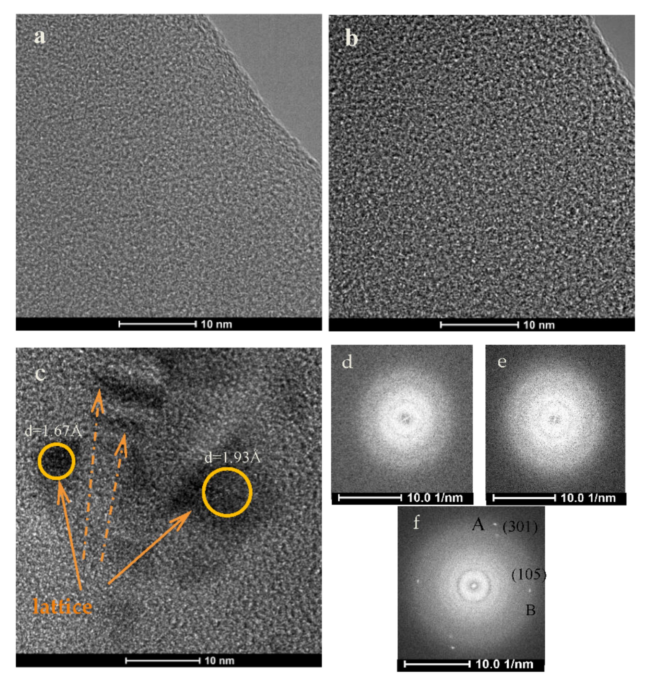
3.2. Microstructure
3.3. Mechanical Properties
3.4. Corrosion Behavior
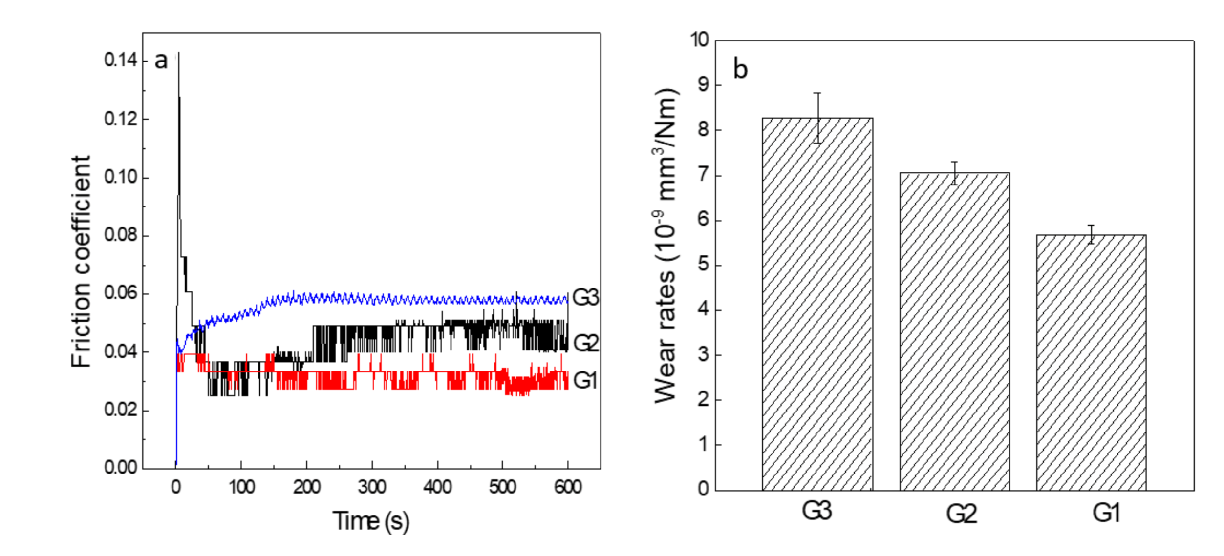
3.5. Tribological Property
4. Conclusions
Author Contributions
Funding
Institutional Review Board Statement
Informed Consent Statement
Data Availability Statement
Acknowledgments
Conflicts of Interest
References
- Sun, W.; Li, M.; Wu, M.; Hu, J. Uniformity of Si-containing diamond-like carbon films deposited at different positions by mesh hollow cathode discharge. Res. Phys. 2019, 14, 102480. [Google Scholar] [CrossRef]
- Konicek, A.R.; Grierson, D.S.; Sumant, A.V.; Friedmann, T.A.; Sullivan, J.P.; Gilbert, P.U.; Sawyer, W.G.; Carpick, R.W. Influence of surface passivation on the friction and wear behavior of ultra nanocrystalline diamond and tetrahedral amorphous carbon thin films. Phys. Rev. B 2012, 85, 155448. [Google Scholar] [CrossRef] [Green Version]
- Ferreira, F.; Serra, R.; Cavaleiro, A.; Oliveira, J. Diamond-like carbon coatings deposited by deep oscillation magne-tron sputtering in Ar-Ne discharges. Diam. Relat. Mater. 2019, 98, 107521. [Google Scholar] [CrossRef]
- Sui, X.; Liu, J.; Zhang, S.; Yang, J.; Hao, J. Microstructure, mechanical and tribological characterization of CrN/DLC/Cr-DLC multilayer coating with improved adhesive wear resistance. Appl. Surf. Sci. 2018, 439, 24–32. [Google Scholar] [CrossRef]
- Imai, T.; Harigai, T.; Tanimoto, T.; Isono, R.; Iijima, Y.; Suda, Y.; Takikawa, H.; Kamiya, M.; Taki, M.; Hasegawa, Y.; et al. Hydrogen-free fluorinated DLC films with high hardness prepared by using T-shape filtered arc deposition system. Vacuum 2019, 167, 536–541. [Google Scholar] [CrossRef]
- Choi, J.; Nakao, S.; Miyagawa, S.; Ikeyama, M. The effects of Si incorporation on the thermal and tribological properties of DLC films deposited by PBII&D with bipolar pulses. Surf. Coat. Technol. 2007, 201, 8357–8361. [Google Scholar] [CrossRef]
- Ding, H.; Fridrici, V.; Guillonneau, G.; Sao-Joao, S.; Geringer, J.; Fontaine, J.; Kapsa, P. Investigation on mechanical properties of tribofilm formed on Ti–6Al–4V surface sliding against a DLC coating by nano-indentation and micro-pillar compression techniques. Wear 2019, 432–433, 202954. [Google Scholar] [CrossRef]
- Wang, X.; Sui, X.; Zhang, S.; Yan, M.; Yang, J.; Hao, J.; Liu, W. Effect of deposition pressures on uniformity, mechanical and tribological properties of thick DLC coatings inside of a long pipe prepared by PECVD method. Surf. Coat. Technol. 2019, 375, 150–157. [Google Scholar] [CrossRef]
- Lan, R.; Ma, Z.; Wang, C.; Lu, G.; Yuan, Y.; Shi, C. Microstructural and tribological characterization of DLC coating by in-situ duplex plasma nitriding and arc ion plating. Diam. Relat. Mater. 2019, 98, 107473. [Google Scholar] [CrossRef]
- Zhang, Y.; Zhang, S.; Sun, D.; Yang, G.; Gao, C.; Zhou, C.; Zhang, C.; Zhang, P. Wide adaptability of Cu nano-additives to the hardness and composition of DLC coatings in DLC/PAO solid-liquid composite lubricating system. Tribol. Int. 2019, 138, 184–195. [Google Scholar] [CrossRef]
- Yang, X.D.; Saito, T.; Nakamura, Y.; Kondo, Y.; Ohtake, N. Mechanical properties of DLC films prepared inside of micro-holes by pulse plas-ma CVD. Diam. Relat. Mater. 2004, 13, 1984–1988. [Google Scholar] [CrossRef]
- Türkmen, D.; Dettenrieder, C.; Forsberg, P.; Mattsson, A.; Nikolajeff, F.; Österlund, L.; Karlsson, M.; Mizaikoff, B. Corrosion detection by infrared attenuated total reflection spectroscopy via diamond-like carbon-coated silicon wafers and iron-sensitive dyes. Sensors 2019, 19, 3373. [Google Scholar] [CrossRef] [PubMed] [Green Version]
- Petereit, B.; Siemroth, P.; Schneider, H.-H.; Hilgers, H. High current filtered arc deposition for ultra thin carbon overcoats on magnetic hard disks and read-write heads. Surf. Coat. Technol. 2003, 174–175, 648–650. [Google Scholar] [CrossRef]
- Sun, Z.; Zhao, W.; Kong, D. Microstructure and mechanical property of magnetron sputtering deposited DLC film. J. Wuhan Univ. Technol. Sci. Ed. 2018, 33, 579–584. [Google Scholar] [CrossRef]
- Li, H.; Wang, Q.; Zhuang, M.; Wu, J. Characterization and residual stress analysis of TiN/TiCN films on AZ31 magnesium alloy by PVD. Vacuum 2015, 112, 66–69. [Google Scholar] [CrossRef]
- Ahmad, I.; Maguire, P.; Lemoine, P.; Roy, S.; McLaughlin, J. Deposition of carbon films onto metal and silicon substrates by filtered cathodic vacuum arc, plasma enhanced CVD and unbalanced magnetron sputtering. Diam. Relat. Mater. 2004, 13, 1346–1349. [Google Scholar] [CrossRef]
- Geretovszky, Z.; Szörényi, T. Compositional and thickness distribution of carbon nitride films grown by PLD in the target plane. Thin Solid Film. 2004, 453–454, 172–176. [Google Scholar] [CrossRef]
- Cai, F.; Zhang, J.; Wang, J.; Zheng, J.; Wang, Q.; Zhang, S. Improved adhesion and erosion wear performance of CrSiN/Cr multi-layer coatings on Ti alloy by inserting ductile Cr layers. Tribol. Int. 2021, 153, 106657. [Google Scholar] [CrossRef]
- Ju, H.; Xu, J. Microstructure and tribological properties of NbN-Ag composite films by reactive magnetron sput-tering. Appl. Surf. Sci. 2015, 355, 878–883. [Google Scholar] [CrossRef]
- Li, H.; Rong, S.; Sun, P.; Wang, Q. Microstructure, residual stress, corrosion and wear resistance of vacu-um annealed TiCN/TiN/Ti films deposited on AZ31. Metals 2017, 7, 5. [Google Scholar] [CrossRef] [Green Version]
- Xu, F.; Luo, L.; Xiong, L.; Liu, Y. Microstructure and corrosion behavior of ALD Al2O3 film on AZ31 magnesium alloy with different surface roughness. J. Magnes. Alloy. 2020, 8, 480–492. [Google Scholar] [CrossRef]
- Lopes, B.B.; Rangel, R.C.; Antonio, C.A.; Durrant, S.F.; Cruz, N.C.; Rangel, E.C. Mechanical and tribological properties of plasma deposited a-C:H:Si:O films. In Nanoindentation in Materials Science; Nemecek, J., Ed.; IntechOpen: London, UK, 2012; pp. 179–202. [Google Scholar]
- Modabberasl, A.; Kameli, P.; Ranjbar, M.; Salamati, H.; Ashiri, R. Fabrication of DLC thin films with improved diamond-like carbon character by the application of external magnetic field. Carbon 2015, 94, 485–493. [Google Scholar] [CrossRef]
- Conceição, K.; de Andrade, V.M.; Trava-Airoldi, V.J.; Capote, G. High antibacterial properties of DLC film doped with nanodiamond. Surf. Coat. Technol. 2019, 375, 395–401. [Google Scholar] [CrossRef]
- Ilic, E.; Pardo, A.; Suter, T.; Mischler, S.; Schmutz, P.; Hauert, R. A methodology for characterizing the electrochemical stability of DLC coated interlayers and interfaces. Surf. Coat. Technol. 2019, 375, 402–413. [Google Scholar] [CrossRef]
- Panjan, P.; Drnovšek, A.; Gselman, P.; Čekada, M.; Panjan, M.; Bončina, T.; Kek Merl, D. Influence of growth defects on the corrosion resistance of sput-ter-deposited TiAlN hard coatings. Coatings 2019, 9, 511. [Google Scholar] [CrossRef] [Green Version]
- Scendo, M.; Staszewska-Samson, K. Effect of temperature on anti-corrosive properties of diamond-like carbon coating on S355 Steel. Materials 2019, 12, 1659. [Google Scholar] [CrossRef] [Green Version]
- Shi, K.; Zhang, Y.; Zhang, J.; Xie, Z. Electrochemical properties of niobium coating for biomedical appli-cation. Coatings 2019, 9, 546. [Google Scholar] [CrossRef] [Green Version]
- Hao, E.; An, Y.; Liu, X.; Wang, Y.; Zhou, H.; Yan, F. Effect of annealing treatment on microstructures, mechanical properties and cavita-tion erosion performance of high velocity oxy-fuel sprayed NiCoCrAlYTa coating. J. Mater. Sci. Technol. 2020, 53, 19–31. [Google Scholar] [CrossRef]
- Liu, Y.; Erdemir, A.; Meletis, E.I. Influence of environmental parameters on the frictional behavior of DLC coatings. Surf. Coat. Technol. 1997, 94–95, 463–468. [Google Scholar] [CrossRef] [Green Version]
- Shaha, K.P.; Pei, Y.T.; Chen, C.Q.; de Hosson, J.T. Pulsed DC sputtered DLC based nanocomposite films: Controlling growth dynamics, microstructure and frictional properties. Mater. Technol. 2011, 26, 15–19. [Google Scholar] [CrossRef]
- Li, G.; Xu, Y.; Xia, Y. Effect of Cr atom plasma emission intensity on the characteristics of Cr-DLC films deposited by pulsed-DC magnetron sputtering. Coatings 2020, 10, 608. [Google Scholar] [CrossRef]


| Process and Operation | Values |
|---|---|
| DC pulsed magnetron sputtering | 280 W; 30 kHz; duty cycle of 50% |
| Bias (V) | −100 |
| Working pressure (Pa) | 0.5~1.0 |
| Flow of Ar (sccm) | 80 |
| Flow of C2H2 (sccm) | 0 (G1); 10 (G2); 20 (G3) |
| Deposition temperature (°C) | 200 |
| Deposition time (min) | 85 |
| Coatings | H/GPa | E/GPa | H/E | H3/E2 |
|---|---|---|---|---|
| G1 | 22.1 | 168 | 0.13 | 0.38 |
| G2 | 20.3 | 156 | 0.13 | 0.34 |
| G3 | 17.4 | 145 | 0.12 | 0.25 |
| Samples | Ecorr (V) | Icorr (A·cm−2) | Rcorr (mm/year) |
|---|---|---|---|
| AZ91 | −1.48 | 7.84 × 10⁻⁴ | 17.77 |
| G1 | −0.94 | 8.31 × 10⁻⁷ | 0.0188 |
| G2 | −0.90 | 5.15 × 10⁻⁷ | 0.0117 |
| G3 | −0.88 | 3.94 × 10⁻⁷ | 0.0089 |
Publisher’s Note: MDPI stays neutral with regard to jurisdictional claims in published maps and institutional affiliations. |
© 2021 by the authors. Licensee MDPI, Basel, Switzerland. This article is an open access article distributed under the terms and conditions of the Creative Commons Attribution (CC BY) license (https://creativecommons.org/licenses/by/4.0/).
Share and Cite
Li, H.; Sun, P.; Cheng, D. Structure and Properties of DLC Films Deposited on Mg Alloy at Different C2H2 Flows of Magnetron Sputtering Process. Coatings 2021, 11, 815. https://doi.org/10.3390/coatings11070815
Li H, Sun P, Cheng D. Structure and Properties of DLC Films Deposited on Mg Alloy at Different C2H2 Flows of Magnetron Sputtering Process. Coatings. 2021; 11(7):815. https://doi.org/10.3390/coatings11070815
Chicago/Turabian StyleLi, Haitao, Pengfei Sun, and Donghai Cheng. 2021. "Structure and Properties of DLC Films Deposited on Mg Alloy at Different C2H2 Flows of Magnetron Sputtering Process" Coatings 11, no. 7: 815. https://doi.org/10.3390/coatings11070815
APA StyleLi, H., Sun, P., & Cheng, D. (2021). Structure and Properties of DLC Films Deposited on Mg Alloy at Different C2H2 Flows of Magnetron Sputtering Process. Coatings, 11(7), 815. https://doi.org/10.3390/coatings11070815