Article

Epitaxial Growth of Single Crystal YAG for Optical Devices

1
Naval Research Laboratory, Washington, DC 20375, USA
2
Department of Chemistry, Clemson University, Clemson, SC 29634, USA
*
Author to whom correspondence should be addressed.
Coatings 2021, 11(6), 644; https://doi.org/10.3390/coatings11060644
Submission received: 30 April 2021 / Revised: 19 May 2021 / Accepted: 20 May 2021 / Published: 27 May 2021
(This article belongs to the Special Issue Epitaxial Thin Films: Properties and Applications)

Abstract

:
We report the latest progress on fabrication of rare earth doped single crystal yttrium aluminum garnet (YAG) core/undoped YAG cladded fibers. Rare-earth doped single crystal core fibers were grown with laser heated pedestal growth methods. In a second step, epitaxial methods were used to grow a single crystalline undoped YAG cladding onto the core fiber. Hydrothermal and liquid phase epitaxy methods utilize the core doped fiber as the seed. X-ray diffraction of cladding reveals an equilibrium (110) morphology. Energy-dispersive X-ray spectroscopy analysis shows there is minimal diffusion of rare-earth dopants into the cladding structure. The use of scandium doping is shown to substitute at the Al3+ site, thereby allowing an additional tunability of refractive index of core structure material besides conventional Y3+ site dopants. The use of these epitaxial growth methods enables material compatibility, tuning of refractive index, and conformal growth of cladding structures onto core fibers for optical devices.

1. Introduction

Recently, there has been growing interest in developing high-power fiber lasers with nearly diffraction limited beam quality. The fiber laser architecture has a number of advantages over bulk laser geometries. A key benefit of fiber-based geometry is reduced thermal issues, including thermal beam distortions and fracture [1]. With planar waveguide geometries, the increased thermal load due to a surface area to volume ratio can result in refractive-index changes based on thermal gradients. The long interaction lengths based on fiber lasers can result in high gain and impressive high power output. In a recent demonstration, a single mode output of 10 kW has been demonstrated from a single aperture in a Yb-doped silica fiber [2]. However, operating at higher power outputs can result in thermal effects including thermal mode instability (TMI) and thermal lensing. In addition, non-linear effects can result from having a long and thin gain medium profile. Stimulated Brillouin scattering (SBS) is one effect seen at high power which can limit further power scaling [3,4]. Much work has been focused on silica-based fibers to date [5,6,7]. The ability to incorporate rare-earth dopants such as ytterbium as laser-active materials into the core of silica-fibers can mitigate photodarkening issues. However, the use of solution doping to incorporate the rare-earth ions can result in the presence of hydroxide impurities in silica-based fibers. In addition, the laser-induced damage at higher powers with glass fibers can damage the small cores. In an effort to mitigate SBS and TMI issues with fibers, one strategy would be to select a different host material, such as crystalline materials, with lower SBS cross-sections and higher thermal conductivities.
One suggested crystalline host material for core fibers that has shown great promise is yttrium aluminum garnet (YAG) [8]. YAG offers numerous advantages over silica including the potential for higher doping concentrations which would enable the use of shorter fiber lengths resulting in lower non-linear effects. YAG offers ∼10 higher thermal conductivity compared to silica which would reduce any stresses in radial direction of the core limiting melting or laser induced damage [9,10]. The lower SBS cross-section for YAG would lead to reduced non-linear effects and enable much greater potential for high peak and average laser power output [11]. YAG has the additional benefit of higher mechanical strength over silica-glass [12]. A recent study suggests that based on thermal and non-linear effects, a Ho doped silica fiber would have a limit of ∼3 kW single frequency power compared to an all crystalline Ho-doped YAG fiber which could generate 35 kW of single frequency eye-safe laser power [13].
In choosing cladding materials to apply to a crystalline YAG core, several characteristics must be considered. Minimizing any coefficient of thermal expansion (CTE) mismatch between materials would reduce any interfacial stress between the core and cladding. The ability to control numerical apertures (NA) through tailoring of the refractive indices can enable high power lasers. Finally, mechanical toughness similar to the core material would help ensure a rugged device. By choosing a proper crystalline cladding, thermal stresses are kept to a minimum between core and clad materials. Tuning of the NA is possible through changing refractive indices by tailoring the composition of the materials. While crystalline cladding selection offers better thermal and mechanical properties than glass, crystalline materials have very defined melting points and low viscosity in the molten state making it difficult to use a preform with a predefined core-clad structure to make a fiber as is commonly used for glass fibers.
The challenge is to maintain the integrity of the crystalline core during the cladding process by maintaining a growth temperature below the melting point of the YAG core. Previously, methods including magnetron sputtering and in situ core-cladding pulling processes during laser-heated pedestal growth (LHPG) have been used to apply crystalline claddings to a crystalline core fiber [14,15,16,17,18]. These have had various successes in applying crystalline claddings, but there have only been limited reports on liquid phase epitaxy and hydrothermal growth being used for depositing crystalline cladding on crystalline core fibers. While the feasibility of using an epitaxial process to grow single crystal undoped YAG cladding on a rare-earth doped single crystal YAG core fiber has been shown previously in a report by Dubinskii et al., a detailed characterization of the crystal quality through single crystal X-ray diffraction has not been demonstrated [19]. Also, the optimization of these growth techniques to control etch-back on fibers followed by actual crystal growth on etched facets has not been reported. In fiber optics there has been a great deal of studies to explore doped-YAG where the dopant is Nd3+, Er3+, Yb3+, or Cr4+. However, due to their low thermal conductivity their applications as high power laser materials is limited [20]. Kim et al. reported on the synthesis and applications of doped sesquioxides such as Sc2O3, Y2O3, and Lu2O3 for high power laser applications because of their high thermal conductivity and high absorption and emission cross sections of 3+ rare-earth ions [21]. Thus based on the optical and thermal conductivity consideration a sesquioxide-doped YAG is a potential candidate for high-power applications. Here, we report on progress in the development of crystalline cladded doped YAG fiber structures as deposited successfully with the liquid phase epitaxy and hydrothermal methods. Physical and optical properties of these fibers are discussed. We also report on progress in the characterization of a scandium (Sc):YAG crystal cladding layer grown epitaxially on a YAG substrate as deposited successfully with the liquid phase epitaxy (LPE) method.

2. Experimental

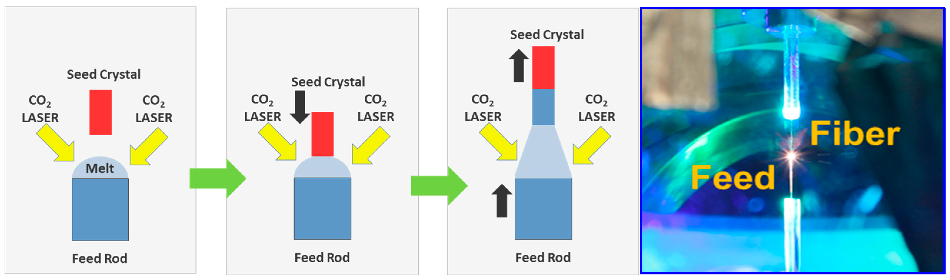
2.1. Fabrication of Doped Yttrium Aluminum Garnet (YAG) Core Fibers

In order to fabricate core and cladding structures for use as low loss waveguide fibers, a two step procedure is used in which the high quality single crystal core fiber must be first fabricated through LHPG. In the second step, the small core fiber is then overclad with other techniques. We have developed a high-precision LHPG system to draw single crystal fibers with lengths over 1 m and diameters as small as 17 µm (Figure 1). The LHPG system is a modified float zone crystal growth technique that utilizes a high-power stabilized CO2 laser to melt a seed crystal that is lowered from above the melt into the molten zone. Once the seed comes into contact with the molten zone, the feed crystal is advanced into the molten zone at a constant rate while a feedback system maintains ∼1% core diameter uniformity on small diameter fibers. The fibers created from LHPG demonstrate good mechanical strength and flexibility.

2.2. Undoped YAG Cladding Processes on Fibers

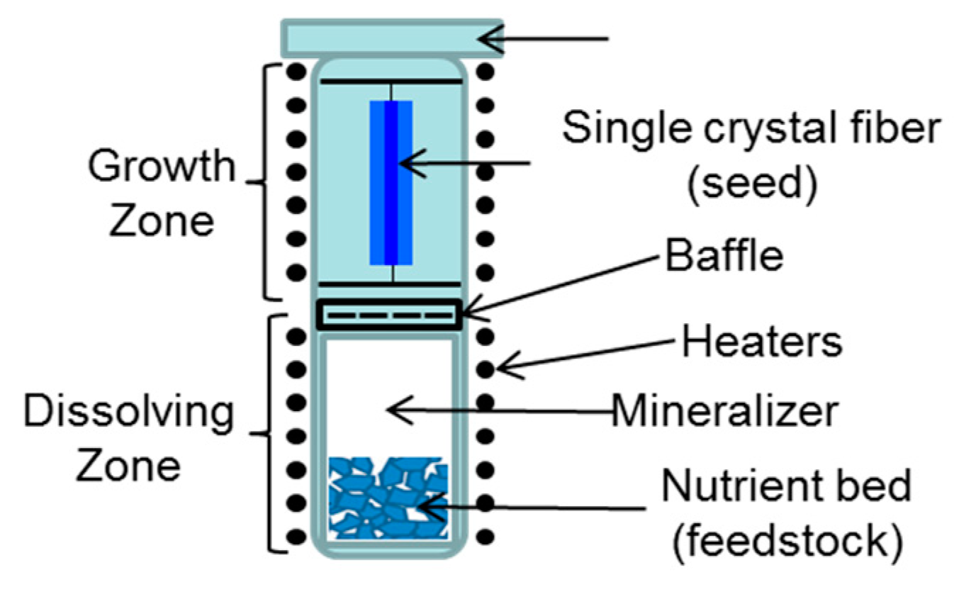
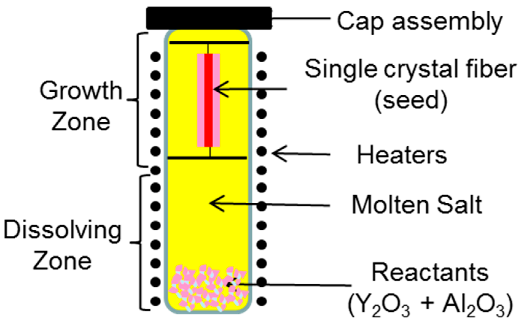
2.2.1. Hydrothermal Growth

Hydrothermal synthesis of YIG (Y3Fe5O12) was first studied by Laudise with the goal of developing a lower temperature process compared to liquid phase epitaxy [22]. However, Czochralski methods were used primarily in the field to grow large YAG boules. Recently, McMillen et al. reported growth of YAG through hydrothermal method using YAG disks [23]. Here, we report on hydrothermal growth using a Yb-doped YAG single crystal core fiber as seed material (Figure 2). The seed substrate is suspended with a ladder in the upper portion of the autoclave and is kept slightly cooler than lower zone where the feedstock material is provided through a baffle located in between two zone throughout the growth process. The feedstock of cladding component oxides in the lower portion of the two zone furnace includes stoichiometric amounts of Y2O3 and Al2O3. K2CO3 mineralizer and water are added to reach a fill level of approximately 50 to 70%. The sealed autoclave is run between 600 and 640 °C to achieve a thermal gradient between dissolution and growth zones, which are separated by a baffle. The thermal gradient and pressures of 15–25 kpsi result in a super-saturation of the cooling region and encourages crystal growth of undoped YAG onto the seed substrate. The core fiber drawn from the LHPG process serves as the seed single crystal fiber in this cladding process.
Various dopants and concentrations can be used with this method to deposit cladding onto the rare-earth doped YAG core fiber. In Figure 3, a 100 μm square shaped Ho3+ doped single crystal YAG fiber was cladded with YAG containing a small dopant concentration (0.25%) of Co2+/Si4+. The Co2+ doping allowed for a simplified blue color identification of the cladding structure. The Si4+ co-dopant was used for charge compensation as Co2+ and Si4+ substitute at the Al3+ site in YAG crystal. Crystal core/clade fiber with a diameter of 140 μm was successfully fabricated as shown in Figure 3. Tuning of the feedstock concentrations were investigated in order to understand boundary conditions for this method. Specifically, the quantity of feedstock and the presence of other reactants were found to determine the etchback conditions. Etchback occurs when the feedstock is nutrient deficient and the fiber would dissolve in a preferential direction. This may be used in the future to achieve smaller core diameter fibers as well as designing specific geometries. Faceted growth may be seen on the end face of an epitaxially cladded fiber as shown in Figure 4. A cleaving and polishing step is used to reveal the core-clad structure prior to splicing between dissimilar materials such as silica [24].

2.2.2. Liquid Phase Epitaxial Growth

In a different approach to achieve an all crystalline core/clad laser fiber, an approach using liquid phase epitaxial growth has shown considerable promise. The approach is similar to the hydrothermal growth process where the solution phase is initially fully saturated with dissolved YAG. The YAG powder or mixture of Y2O3 and Al2O3 reactants are added to molten flux at high temperature (>1100 °C) until it exceeds saturation. The molten flux containing PbO and B2O3 is stirred in the platinum crucible with the YAG material while the single crystal core fiber is immersed in the flux as a seed material and crystal is grown around the fiber (Figure 5). With a reaction temperature kept between 1000–1050 °C, well below the melting temperature of YAG, the seed-doped YAG fiber serves as the nucleation site for crystal growth for undoped YAG. As the temperature of the molten flux is slowly lowered, the saturation limit for dissolved YAG drops and the excess comes out of solution and deposits on the fiber. Isothermal growth conditions within the furnace ensure a uniform and homogenous composition throughout the grown cladding.
Sc:YAG crystal layers were grown from PbO−B2O3 fluxed melts using an isothermal LPE dipping method similar to that described in the literature [25,26]. The substrates were polished (100) wafers of Czochralski-grown yttrium aluminum garnet of dimensions 10 × 10 mm2 and approximately 0.5 mm thick. The melts were prepared from an appropriate amount of oxides in the same stoichiometric ratios as desired film compositions. Upon removal from the melt, sample was rinsed with HCl acid to remove any residual flux.

3. Results

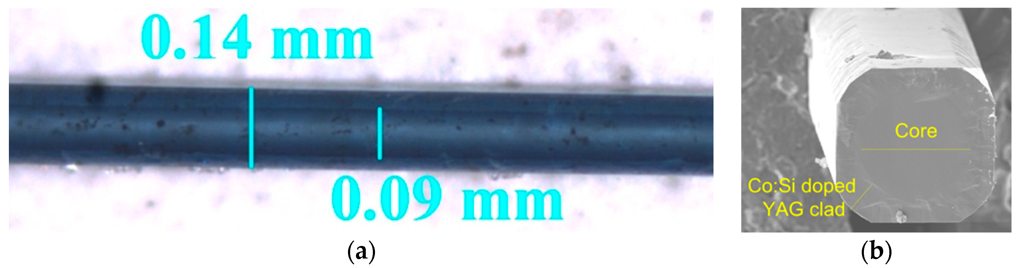
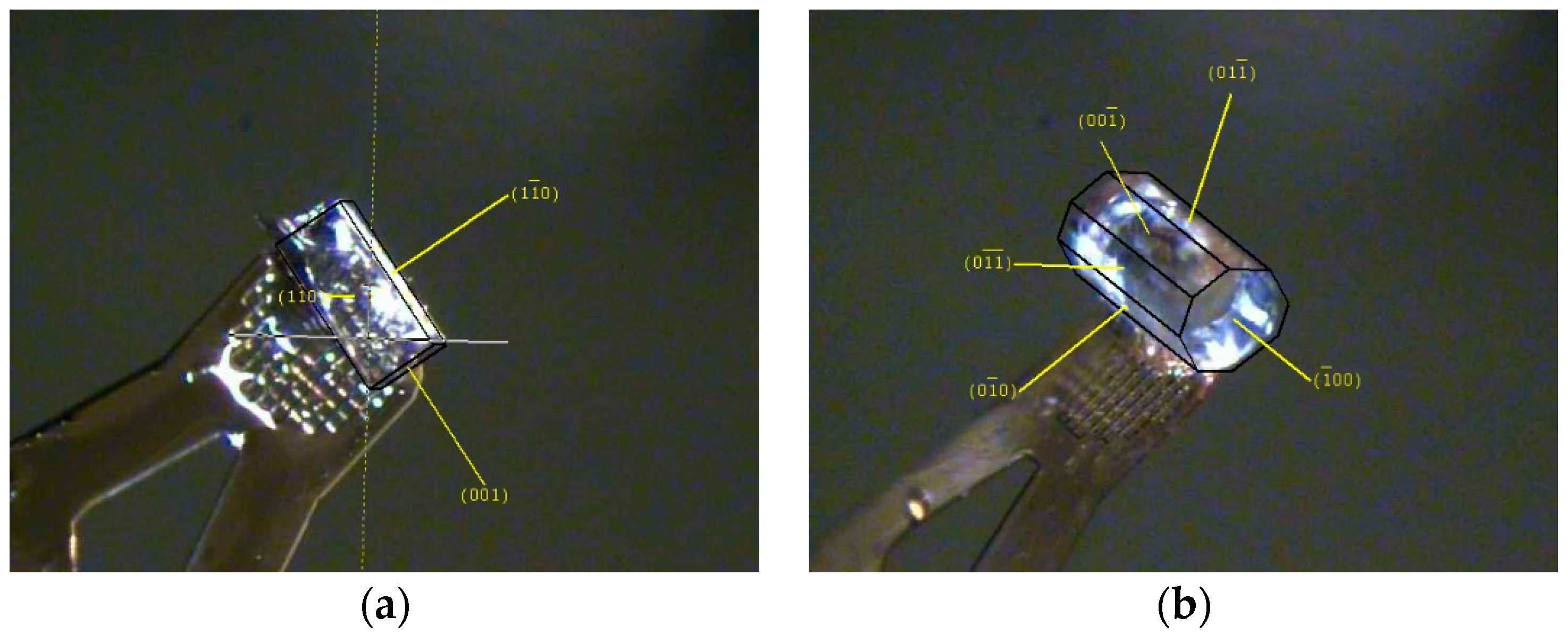
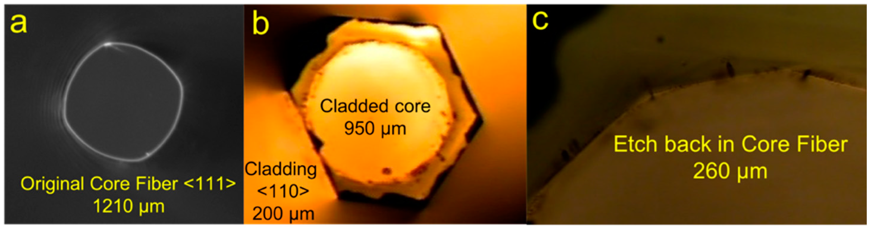
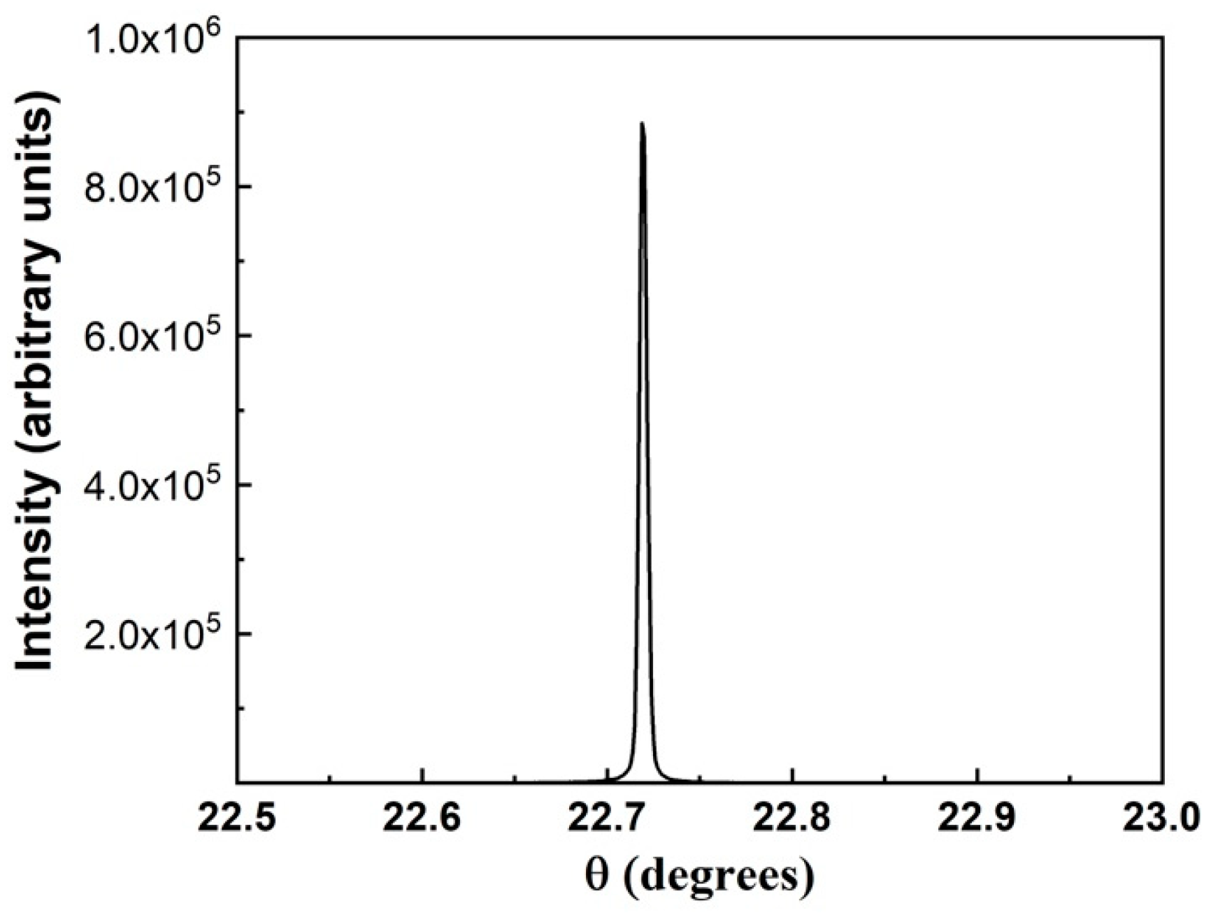
3.1. Characterization

Energy-dispersive X-ray spectroscopy (EDX) was used to characterize the composition of the cladded YAG fiber. Elemental analysis of the cladding and core regions reveals a stoichiometry close to the desired Y3Al5O12 stoichiometry of undoped YAG phases (Table 1). The core fiber shows a dopant concentration of roughly 14% Yb, as expected from the doped core fiber grown from LHPG. In addition, there is a sharp gradient in the detection of the concentration of Yb at the core–clad interface. This suggests minimal diffusion of rare-earth ions occurred during the hydrothermal growth of cladding. Diffusion of the dopant would cause scattering losses and less confinement of light in the core.
Single crystal X-ray diffraction (XRD) was used to identify the crystal structure of the cladding and identify the crystallographic directions of the different facets (Figure 6). Initially the Yb:YAG core fiber shows multiple facets and possible growth planes prior to hydrothermal cladding. However, when there was sufficient growth time in the autoclave, the equilibrium morphology that was favored was clearly the (110) form as demonstrated by undoped YAG cladding growth planes. The angles between (110) and (1 1 ¯ 0) are predicted to be 90 degrees and this is visually depicted as a square cladding. The doped core region has slightly lower unit cell parameters due to the smaller ionic radius of Yb3+ (0.86 Å) compared to the Y3+ (0.89 Å) in YAG garnet (Table 2).
The original core fiber as drawn from LHPG used for the hydrothermal cladding process shown in Figure 7a can be seen with corners. With insufficient feedstock reactants, the dissolution of a core fiber can result in slight etchback of the original substrate (Figure 7b–c). The radius of curvature remains similar, yet the faces of the dissolution form (D-form) can flatten to form additional faces. It has been suggested that the growth form (G-form) of a single crystal substrate will eventually switch from the fastest growing faces to the slowest and reach an equilibrium state [27]. The D-form for a substrate will exhibit the faces with the greatest shift velocities. This has been shown for acid etching of garnet crystals, where the (111) form was the most frequent D-form for single crystal sphere substrates [28]. For the growth of bulk YAG, a chemical bonding theory of single crystal growth was used to determine the (100) growth direction to be the slowest [29]. In initial experiments, the growth in (111) directions was the fastest-resulting cladding. For the perfect crystal, the lowest energy plane would have the slowest growth rate, which would be the (110) plane. In a terminated growth reaction, the observed end-face of a fiber with the hexagonal (111) planes growing out and eventually would be bound by the lowest energy plane (110), before coarsening completely to the equilibrium morphology. These etch-back and growth processes require a considerable amount of effort to understand and optimize. However, the tunability of experimental conditions such as nutrient concentration and processing temperature can result in a well-defined faceted core fiber followed by epitaxial cladding growth [30].
A high-resolution X-ray diffractometer using CuKα1 radiation was used to measure the rocking curve for the hydrothermally grown cladding using (022) reflection and a FWHM of 0.047° was determined (Figure 8). The intensity for a polycrystalline sample varies as a function of square of the amplitude of the structure factor:
I ∝ |F|2 ⇒ I = C |F|2
If we take the intensity ratio of the 400 and 800 peaks as previously reported [31],
I400/I800 = |F400|2/|F800|2 = 29/9 = 3.22
∴ |F400|/|F800| ≅ 1.8
For a nearly perfect crystal the intensity of the different ratios of peaks varies as:
I ∝ |F|
Thus we expect the ratio of intensities for a nearly perfect crystal to be:
I400/I800 = |F400|/|F800| ≅ 1.8
For a single crystal YAG cladding grown epitaxially, our measurements show the ratio of the measured intensities of 400 to 800 reflections are ∼1.8 in agreement with the expected value. In addition, the full width half maximum (FWHM) of (400) is 169 arc secs, consistent with very high crystalline quality [32,33]. The values for FWHM demonstrates lower contributions from dislocation density, strain, and any other defects present in the crystal. In comparison, previous reports of YAG garnets grown with the Czochralski method and horizontal directional solidification method were determined to have FWHM of 1372 and 947 arc secs, respectively [34,35].

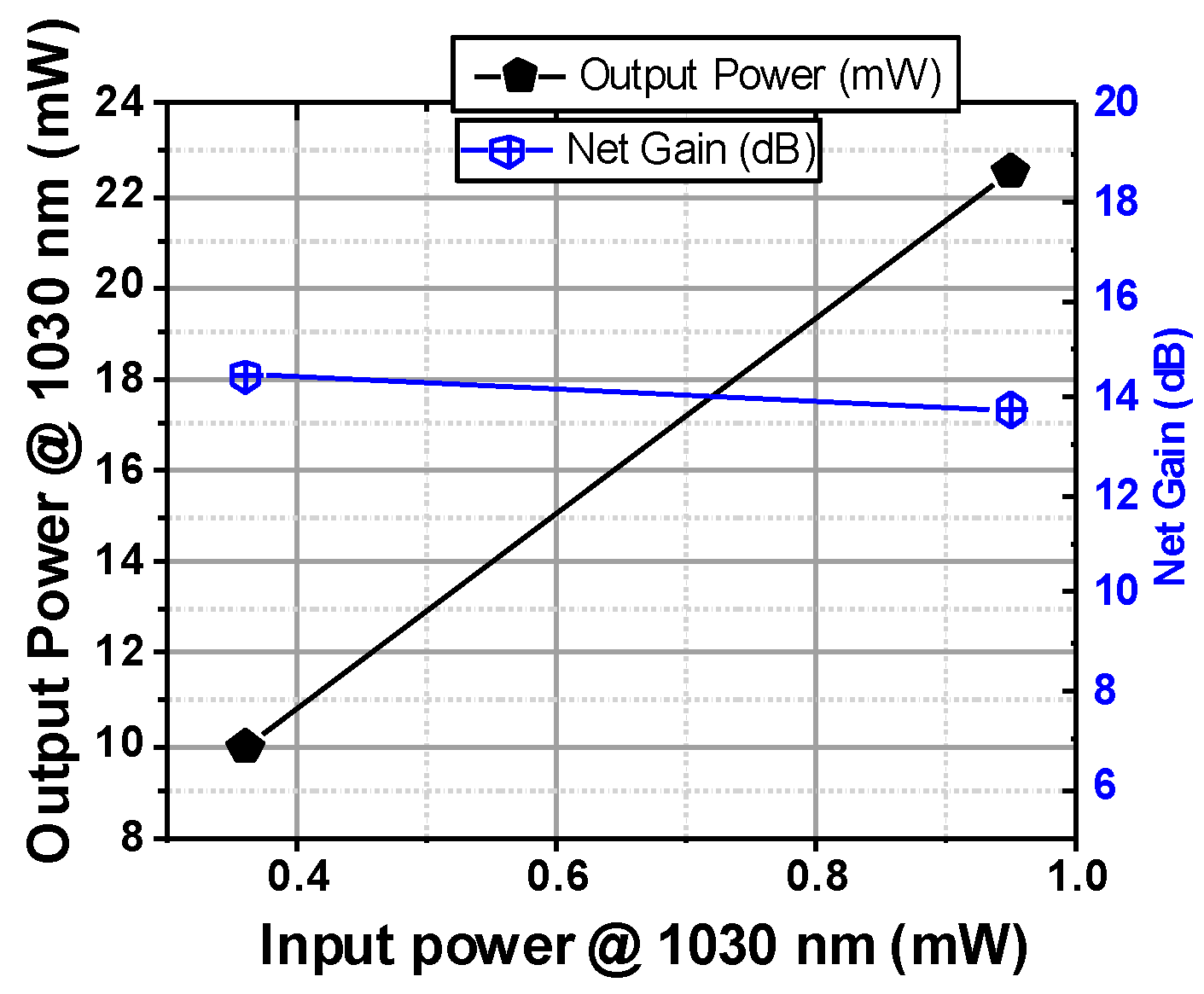
3.2. Demonstrated Power Gain in Hydrothermal Cladded Fiber

A 100 µm Yb:YAG core, undoped YAG fiber structure whose cladding was fabricated by the hydrothermal crystal growth method was used for the gain measurements. The cladding thickness varied radially and ranged from ∼15–40 µm. The refractive index of undoped YAG is lower than that of doped YAG. Based on the index of 10% Yb:YAG and undoped YAG, the numerical aperture (NA) of the fiber core was ∼0.1. Gain was measured using a 1025 nm DFB laser as the seed and a 970 nm diode pump operating at 10% duty cycle to minimize heating of the sample (Figure 9). Both pump and seed were launched into the core of the 10% Yb; YAG fiber. The launched seed signal temporally overlapping the pump was 0.268 mW. A net peak gain of 14 dB was measured in a 7 mm long sample. For single crystal fiber structures to be a viable technology, mating the fiber to silica fiber technology is critical. We have demonstrated splicing of unclad 100 µm single crystal YAG fiber to 65 µm core/125 µm clad silica fiber. A splice loss of 0.33 dB was measured with a splice tensile strength of ∼50 kpsi.

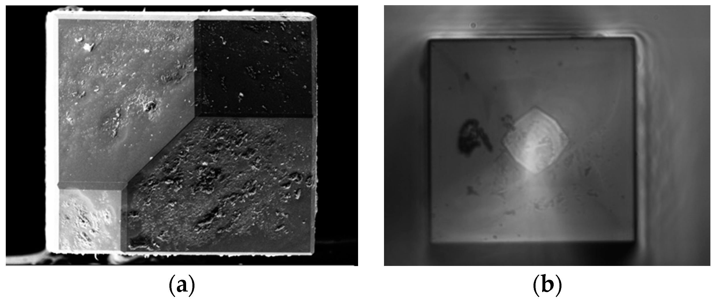
3.3. Liquid Phase Epitaxial Growth of Scandium (Sc):YAG

For an all crystalline core/clad fiber, the epitaxial growth techniques allow for matching of cladding crystal structures to the core. Matching of the lattice constants and thermal expansion minimizes stresses and interface losses. The undoped YAG material has the lowest refractive index (1.814) compared to other garnets. While doping allows for tunability of the refractive index within the garnet family, most reported doping is restricted at the Y-site of standard Y3Al5O12. Here, we expand the range of tuning of the refractive index by doping with Sc where the Al ions can be substituted and report on investigating some of the properties within the Sc-substituted YAG composition, Y3(Sc,Al)5O12.
In order to better predict the impact of Sc3+ doping, we investigated possible effects on the overall structure. The crystal structure of YAG and lattice substitutions has been reported in the literature [36]. The crystal structure of YAG and the local environment around Al3+ and Y3+ ions is shown in Figure 10. The larger Y3+ ion (1.019 Å) goes in a dodecahedral site where it is surrounded by 8 O2− ions. The smaller Al3+ ion goes on octahedral and tetrahedral sites. The ionic radii of Al3+ in octahedral and tetrahedral coordination are 0.535 Å and 0.39 Å respectively [36]. The occupancy of Al3+ ion in the octahedral:tetrahedral sites is in a 2:3 ratio. If A represents Y3+ in the dodecahedral site while B and C represent Al3+ in octahedral and tetrahedral sites, respectively, then the YAG structure can be represented as A3(B2C3)O12. The rare-earth ions (Yb3+ and Ho3+ in our case) substitute for Y3+ ion on the A site. The ionic radii of Sc3+ in eight-fold coordination (A-site) is 0.87 Å while in six-fold coordination (B-site) it is 0.745 Å. Scandium substitution on both A-site (for Y3+) and B-site (for Al3+) has been reported in the literature [37]. When the Sc3+ ion substitutes for larger Y3+ ion (on A-site) the unit cell size decreases and when it substitutes for the smaller Al3+ ion (on B-site) the unit cell size increases [37]. When Sc substitutes on all the B-sites the formula can be represented as Y3Sc2Al3O12. We used VESTA analysis software to calculate the crystal structure of YAG as a function of Sc substitution on the B-site. The shift in d400 peak as would be observed using X-ray diffraction is shown in Figure 11a. This is shown as an increase in d-spacing in Figure 11b or as a shift to lower angles for the (400) peak in 2θ as shown in Figure 11a. Our initial results based on six various compositions indicate greater Sc substitution leads to larger unit cell parameters (Figure 11b). However, it is possible the Sc3+ (0.745 Å) ions can substitute the larger Y3+ (1.019 Å) ions. The Y−O polyhedral sites contain a dodecahedral site for the Y3+ ions, which is typically the site for rare-earth dopants such as Nd3+. In this approximation, substitution at the A-site would lead to decreased unit cell parameters as Sc3+ dopant concentration increased, as previously shown in one report [38]. The compositions of the planar substrates were analyzed with energy-dispersive spectroscopy (EDS) and confirmed to be similar to the composition of the prepared melt (Figure 12). The measured concentration level of Y is consistent with that of undoped YAG, suggesting the Sc doping is confined to the Al site.
Sc-YAG films were measured using ellipsometry for changes in polarization of light reflected from samples using a knife-edge illumination technique. This technique avoids the disturbing backside-reflections that can occur from thin transparent substrates by using a beam cutter. Refractive index and a non-zero extinction coefficient were obtained by fitting a Cauchy optical model to measurement data, as shown in Figure 13 for an undoped YAG substrate. For the uncoated YAG substrate measurement, a refractive index, n, of 1.820 is measured at 1 µm that is slightly higher than the theoretical values of 1.814 for an undoped Y3Al5O12 (YAG) at 1 µm. After the epitaxial growth of Sc-YAG films, refractive indices at 1 µm were measured to be 1.837 and 1.841 for Y3(Sc0.33Al1.67)Al3O12 and Y3(Sc0.67Al1.33)Al3O12, respectively. The addition of Sc3+ leads to a higher refractive index, while YAG is still ideal for the outer cladding of a fiber. Any need for additional dopants allows for precise tailoring of the inner cladding refractive index for an all-crystalline double-clad fiber laser.
In order to further examine the possible sites for scandium substitution, we used Raman spectroscopy to look at the stretching vibrations for the (AlO4) unit. The lattice strains that are introduced by doping YAG at the Y3+ site by Nd3+ typically result in a blue shifting of modes [39]. In the Sc-doped YAG films, we observe that the longer Sc–O bonds results in distinct peaks in the Raman spectra based on a regular substituting of Al3+ by heavier Sc3+ ions. In Figure 14, the peaks seen between 680 and 1350 cm−1 can be assigned to the internal stretching vibrations between scandium ions and oxygen in the tetrahedral (Sc,Al−O4) unit [40,41]. A detailed analysis of the Raman spectra of compositions will described in a subsequent communication.

4. Summary

The hydrothermal and liquid phase epitaxial growth of YAG shows great promise for single crystal cladding onto single crystal core fibers. These epitaxial techniques are versatile epitaxial methods to growth undoped YAG cladding of various thicknesses onto doped YAG core fibers, potentially for tailoring of optical laser devices. These techniques also potentially allow for double cladding of doped core fibers. We have demonstrated that careful consideration of feedstock concentrations is important for controlled etchback of original core fiber. In addition, growth experiments of single crystal YAG cladding demonstrated (111) morphology if terminated early before reaching the equilibrium (110) form. Our present work shows a demonstration of the versatility of these epitaxial growth methods to grow single crystal cladding onto a single crystal core fiber. A Yb-doped YAG core fiber was cladded with undoped YAG and demonstrated a 14 dB gain. A liquid phase epitaxial method was used to grow varied compositions of single crystal Sc:YAG films onto YAG substrates, showing a higher refractive index for doped compositions. This work may serve as a basis for the continued development of epitaxially grown films for other doped YAG compositions in optical devices.

Author Contributions

Conceptualization, W.K., L.B.S., S.B., and J.S.; methodology, S.N.Q., J.K., and B.S.; formal analysis, S.N.Q. and S.B.Q.; writing—original draft preparation, S.N.Q.; writing—review and editing, W.K.; funding acquisition, J.S. and J.K. All authors have read and agreed to the published version of the manuscript.

Funding

This research was funded by Office of Naval Research, grant No. N0001418WX00846.

Institutional Review Board Statement

Not applicable.

Informed Consent Statement

Not applicable.

Data Availability Statement

Data is contained within the article.

Acknowledgments

The authors would like to thank Alyssa Mock for valuable discussions on ellipsometry.

Conflicts of Interest

The authors declare no conflict of interest. The funders had no role in the design of the study; in the collection, analyses, or interpretation of data; in the writing of the manuscript; or in the decision to publish the results.

References

  1. Nilsson, J.; Payne, D.N. High-power fiber lasers. Science 2011, 332, 921–922. [Google Scholar] [CrossRef] [PubMed]
  2. Fomin, V.; Abramov, M.; Ferin, A.; Abramov, A.; Mochalov, D.; Platonov, N.; Gapontsev, V. 10 kW single-mode fiber laser. In Proceedings of the Symposium on High-Power Fiber Lasers, 14th International Conference on Laser Optics SyTu-1.3, St. Petersburg, Russia, 28 June–1 July 2010. [Google Scholar]
  3. Dawson, J.W.; Messerly, M.J.; Beach, R.J.; Shverdin, M.Y.; Stappaerts, E.A.; Sridharan, A.K.; Pax, P.H.; Heebner, J.E.; Siders, C.W.; Barty, C.P.J. Analysis of the scalability of diffraction-limited fiber lasers and amplifiers to high average power. Opt. Express 2008, 16, 13240–13266. [Google Scholar] [CrossRef] [PubMed]
  4. Jauregui, C.; Eidam, T.; Otto, H.J.; Stutzki, F.; Jansen, F.; Limpert, J.; Tünnermann, A. Physical origin of mode instabilities in high-power fiber laser systems. Opt. Express 2012, 20, 12912–12925. [Google Scholar] [CrossRef] [PubMed]
  5. Sincore, A.; Bradford, J.D.; Cook, J.; Shah, L.; Richardson, M.C. High average power thulium-doped silica fiber lasers: Review of systems and concepts. IEEE J. Sel. Top. Quantum Electron. 2018, 24, 1–8. [Google Scholar] [CrossRef]
  6. Zheng, J.; Zhao, W.; Zhao, B.; Hou, C.; Li, Z.; Li, G.; Gao, Q.; Ju, P.; Gao, W.; She, S.; et al. 4.62 kW excellent beam quality laser output with a low-loss Yb/Ce co-doped fiber fabricated by chelate gas phase deposition technique. Opt. Mater. Express 2017, 7, 1259–1266. [Google Scholar] [CrossRef]
  7. Beier, F.; Hupel, C.; Kuhn, S.; Hein, S.; Nold, J.; Proske, F.; Sattler, B.; Liem, A.; Jauregui, C.; Limpert, J.; et al. Single mode 4.3 kW output power from a diode-pumped Yb-doped fiber amplifier. Opt. Express 2017, 25, 14892–14899. [Google Scholar] [CrossRef] [PubMed]
  8. Parthasarathy, T.; Hay, R.S.; Fair, G.; Hopkins, F.K. Predicted performance limits of yttrium aluminum garnet fiber lasers. Opt. Eng. 2010, 49, 094302. [Google Scholar] [CrossRef]
  9. Dawson, J.W.; Messerly, M.J.; Heebner, J.E.; Pax, P.H.; Sridharan, A.K.; Bullington, A.L.; Beach, R.J.; Siders, C.W.; Barty, C.P.J.; Dubinskii, M. Power scaling analysis of fiber lasers and amplifiers based on non-silica materials. In Proceedings of the Laser Technology for Defense and Security VI, Orlando, FL, USA, 5–9 April 2010; Volume 7686, p. 768611. [Google Scholar]
  10. Brown, D.C.; Hoffman, H.J. Thermal, stress, and thermo-optic effects in high average power double-clad silica fiber lasers. IEEE J. Quantum Electron. 2001, 37, 207–217. [Google Scholar] [CrossRef]
  11. Smith, R.G. Optical power handling capacity of low loss optical fibers as determined by stimulated Raman and Brillouin scattering. Appl. Opt. 1972, 11, 2489–2494. [Google Scholar] [CrossRef]
  12. Mezeix, L.; Green, D.J. Comparison of the mechanical properties of single crystal and polycrystalline yttrium aluminum garnet. Int. J. Appl. Ceram. Technol. 2006, 3, 166–176. [Google Scholar] [CrossRef]
  13. Kim, W.; Shaw, B.; Bayya, S.; Askins, C.; Peele, J.; Rhonehouse, D.; Myers, J.; Thapa, R.; Bowman, S.; Gibson, D.; et al. Cladded single crystal fibers. MS&T 2016, 2016, 4–8. [Google Scholar]
  14. Bera, S.; Nie, C.D.; Harrington, J.A.; Chick, T.; Chakrabarty, A.; Trembath-Reichert, S.; Chapman, J.; Rand, S.C. Cladding single crystal YAG fibers grown by laser heated pedestal growth. In Proceedings of the Solid State Lasers XXV: Technology and Devices, San Francisco, CA, USA, 13–18 February 2016; p. 97260C. [Google Scholar] [CrossRef]
  15. Kim, W.; Shaw, B.; Bayya, S.; Askins, C.; Peele, J.; Rhonehouse, D.; Meyers, J.; Thapa, R.; Gibson, D.; Sanghera, J. Cladded single crystal fibers for high power fiber lasers. In Proceedings of the Photonic Fiber and Crystal Devices: Advances in Materials and Innovations in Device Applications X, San Diego, CA, USA, 28 August–1 September 2016; Volume 9958, p. 99580O. [Google Scholar]
  16. Kim, W.; Bayya, S.; Shaw, L.B.; Myers, J.; Qadri, S.N.; Thapa, R.; Askins, C.; Peele, J.; Rhonehouse, D.; Bowman, S.; et al. Crystal fiber lasers. In Proceedings of the Photonic Fiber and Crystal Devices: Advances in Materials and Innovations in Device Applications XI, San Diego, CA, USA, 6–10 August 2017. [Google Scholar] [CrossRef]
  17. Shaw, L.B.; Bayya, S.; Kim, W.; Myers, J.; Rhonehouse, D.; Qadri, S.N.; Askins, C.; Peele, J.; Thapa, R.; Gibson, D.; et al. Fabrication of cladded single crystal fibers for all—crystalline fiber lasers. In Proceedings of the Advanced Photonics 2018 (BGPP, IPR, NP, NOMA, Sensors, Networks, SPPCom, SOF), Zurich, Switzerland, 2–5 July 2018. [Google Scholar]
  18. Shaw, L.B.; Askins, C.; Kim, W.; Bayya, S.; Peele, J.; Rhonehouse, D.; Thapa, R.; Gibson, D.; Myers, J.; Gattass, R.R.; et al. Development of Clad Single Crystal Fiber. In Proceedings of the Photonics and Fiber Technology 2016 (ACOFT, BGPP, NP), Sydney, Australia, 5–8 September 2016. [Google Scholar] [CrossRef]
  19. Dubinskii, M.; Zhang, J.; Fromzel, V.; Chen, Y.; Yin, S.; Luo, C. Low-loss ‘crystalline-core/crystalline-clad’ (C4) fibers for highly power scalable high efficiency fiber lasers. Opt. Express 2018, 26, 5092–5101. [Google Scholar] [CrossRef] [PubMed]
  20. Kim, W.; Baker, C.; Villalobos, G.; Frantz, J.; Shaw, B.; Lutz, A.; Bryan, S.; Frederic, K.; Machael, H.; Jasbinder, S.; et al. Synthesis of high purity Yb3+-Doped Lu2O3 powder for high power solid-state lasers. J. Am. Ceram. Soc. 2011, 94, 3001–3005. [Google Scholar] [CrossRef]
  21. Kim, W.; Baker, C.; Villalobos, G.; Frantz, J.; Shaw, B.; Sadowski, B.; Hunt, M.; Aggarwal, I.; Sanghera, J. Highly transparent ceramics obtained from jet milled sesquioxide powders synthesized by co-precipitation method. Opt. Mater. Express 2014, 4, 2497. [Google Scholar] [CrossRef]
  22. Laudise, R.A.; Crocket, J.H.; Ballman, A.A. The hydrothermal crystallization of yttrium iron garnet and yttrium gallium garnet and a part of the crystallization diagram Y2O3-Fe2O3-H2O-Na2CO3. J. Phys. Chem. 1961, 65, 359–361. [Google Scholar] [CrossRef]
  23. Mcmillen, C.D.; Mann, M.; Fan, J.; Zhu, L.; Kolis, J.W. Revisiting the Hydrothermal growth of YAG. J. Cryst. Growth 2012, 356, 58–64. [Google Scholar] [CrossRef]
  24. Thapa, R.; Gibson, D.; Gattass, R.R.; Askins, C.; Kim, W.; Bayya, S.; Shaw, L.B.; Sanghera, J.S. Fusion splicing of highly dissimilar YAG crystal fiber and silica fiber with reaction bonding. Opt. Mater. Express 2016, 6, 2560. [Google Scholar] [CrossRef]
  25. Ferrand, B.; Pelenc, D.; Chartier, I.; Wyon, C. Growth by LPE of Nd: YAG single crystal layers for waveguide laser applications. J. Cryst. Growth 1993, 128, 966–969. [Google Scholar] [CrossRef]
  26. Ferrand, B.; Chambaz, B.; Couchaud, M. Liquid phase epitaxy: A versatile technique for the development of miniature optical components in single crystal dielectric media. Opt. Mater. 1999, 11, 101–114. [Google Scholar] [CrossRef]
  27. Lacmann, R.; Franke, W.; Heimann, R. The dissolution forms of single crystal spheres: I. Theory for the molecular-kinetics interpretation. J. Cryst. Growth 1974, 26, 107–116. [Google Scholar] [CrossRef]
  28. Hartmann, E.; Beregi, E. Face statistics on the dissolution forms of garnet crystals. J. Cryst. Growth 1993, 128, 74–81. [Google Scholar] [CrossRef]
  29. Sun, C.; Xue, D. Chemical bonding theory of single crystal growth and its application to ϕ 3′′ YAG bulk crystal. CrystEngComm 2014, 16, 2129–2135. [Google Scholar] [CrossRef]
  30. Kim, W.; Bayya, S.; Shaw, B.; Myers, J.; Qadri, S.N.; Thapa, R.; Gibson, D.; Mcclain, C.; Kung, F.; Kolis, J.; et al. Hydrothermally cladded crystalline fibers for laser applications [Invited]. Opt. Mater. Express 2019, 9, 2716. [Google Scholar] [CrossRef]
  31. NIST Inorganic Crystal Structure Database; NIST Standard Reference Database Number 3; National Institute of Standards and Technology; Gaithersburg, M.D. 20899; National Institute of Standards and Technology: Gaithersburg, MD, USA, 2018. [CrossRef]
  32. Qadri, S.B.; Horwitz, J.S.; Chrisey, D.B.; Auyeung, R.C.Y.; Grabowski, K.S. X-ray characterization of extremely high quality (Sr,Ba)TiO3 films grown by pulsed laser deposition. Appl. Phys. Lett. 1995, 66, 1605. [Google Scholar] [CrossRef]
  33. Qadri, S.B.; Dinan, J.H. X-ray determination of dislocation density in epitaxial ZnCdTe. Appl. Phys. Lett. 1985, 47, 1066–1068. [Google Scholar] [CrossRef]
  34. Chani, V.I.; Yoshikawa, A.; Kuwano, Y.; Hasegawa, K. Growth of Y3Al5O12: Nd fiber crystals by micro-pulling-down technique. J. Cryst. Growth 1999, 204, 155–162. [Google Scholar] [CrossRef]
  35. Zhang, M.; Guo, H.; Han, J.; Zhang, H.; Xu, C. Distribution of Neodymium and properties of Nd:YAG crystal by horizontal directional solidification. J. Cryst. Growth 2012, 340, 130–134. [Google Scholar] [CrossRef]
  36. Upasani, M. Synthesis of Y3Al5O12: Eu and Y3Al5O12: Eu, Si phosphors by combustion method: Comparative investigations on the structural and spectral properties. J. Adv. Ceram. 2016, 5, 344–355. [Google Scholar] [CrossRef] [Green Version]
  37. Ferrier, A.; Ilas, S.; Goldner, P.; Louchet-Chauvet, A. Scandium doped Tm:YAG ceramics and single crystals: Coherent and high resolution spectroscopy. J. Lumin. 2018, 194, 116–122. [Google Scholar] [CrossRef]
  38. Kokta, M.; Laboratories, B.; Hill, M. Solubility enhancement of Nd7+ in scandium-substituted rare earth- aluminum garnets. J. Solid State Chem. 1973, 8, 39–42. [Google Scholar] [CrossRef]
  39. Kostić, S.; Lazarević, Z.Ž.; Radojević, V.; Milutinović, A.; Romčević, M.; Romčević, N.Ž.; Valčić, A. Study of structural and optical properties of YAG and Nd:YAG single crystals. Mater. Res. Bull. 2015, 63, 80–87. [Google Scholar] [CrossRef]
  40. Ding, S.; Ren, H.; Li, H.; He, A. Hardness, Raman spectrum, thermal properties, and laser damage threshold of Y3Sc2Ga3O12 single crystal. J. Mater. Sci. Mater. Electron. 2021, 32, 1616–1622. [Google Scholar] [CrossRef]
  41. Lupei, A.; Lupei, V.; Hau, S.; Gheorghe, C.; Voicu, F. Structure and temperature effects on Nd3+ spectra in polycrystalline mixed scandium aluminum garnets Y3ScxAl5-xO12. Opt. Mater. 2015, 47, 465–472. [Google Scholar] [CrossRef]
Figure 1. Schematic of laser-heated pedestal growth (LHPG) technique at the Naval Research Laboratory resulting in a fiber with high flexibility. A feedback mechanism controls the pulling rate to achieve as small as 17 μm fiber diameter from a 100 μm feedstock.
Coatings 11 00644 g001
Figure 2. Hydrothermal chamber for cladding growth showing the bottom dissolving zone and an upper growth zone for growing single crystal cladding on single crystal fiber.
Coatings 11 00644 g002
Figure 3. Photos of a 19 mm long, 90 µm core-cladded fiber using the hydrothermal method. (a) Optical microscope image of the side profile showing core inside the cladding structure. (b) Scanning electron microscope (SEM) image of cross-section, showing the 90 µm yttrium aluminum garnet (YAG) core fiber cladded with Co2+:Si4+ doped YAG cladding.
Coatings 11 00644 g003
Figure 4. As grown end face of 208 µm × 208 µm fiber, followed polishing. (a) SEM image of as grown end face after hydrothermal growth. (b) Confocal microscope image of polished fiber cross-section.
Coatings 11 00644 g004
Figure 5. Schematic showing liquid phase epitaxy growth setup of YAG crystal cladding.
Coatings 11 00644 g005
Figure 6. X-ray diffraction (XRD) of a single crystal doped YAG core before and after cladding with dimensions 208 μm. (a) Miller indices of Yb:YAG core fiber crystal planes before cladding; (b) Miller indices of undoped YAG cladding after hydrothermal growth.
Coatings 11 00644 g006
Figure 7. (a) Original core fiber as drawn from LHPG to be used as seed and core fiber for cladding by hydrothermal method. (b) Doped core fiber cladded with undoped YAG cladding. (c) A single crystalline core reveals some etchback had occurred during hydrothermal process.
Coatings 11 00644 g007
Figure 8. Rocking curve of hydrothermally grown undoped YAG cladding using a (022) reflection and CuKα1 radiation.
Coatings 11 00644 g008
Figure 9. Gain measurements in cladded fiber. The pump was coupled into cladding and signal into the core. A core loss of 0.15 dB/cm (measured at 1300 nm) is reported.
Coatings 11 00644 g009
Figure 10. Unit cell showing the positions of Y3+, Al3+ and O2− in YAG cubic crystal structure. Y3+ in A-site (dodecahedral), Al3+ in B-site (octahedral) and Al3+ in C-site (tetrahedral) are also shown.
Coatings 11 00644 g010
Figure 11. (a) A shift to lower 2θ angles is predicted in X-ray diffraction (XRD) diffraction peak for (400) based on increased Sc3+ substitution (x) on B-site. (b) Line shows theoretical d-spacing calculations based on Sc3+ substitution at the B-sites in Y3(Al2-xScx)Al3O12. Experimental values from Sc substitution shown as points, showing an increased d-spacing for greater Scandium content in the composition series.
Coatings 11 00644 g011
Figure 12. Energy-dispersive spectroscopy (EDS) analysis of planar substrate reveals deposited Sc-doped composition is similar to the prepared melt composition Y3(Sc0.67Al1.33)Al3O12.
Coatings 11 00644 g012
Figure 13. Optical model and fit for a bare undoped YAG substrate from measurements using ellipsometry, showing n, refractive index, and k, a non-zero extinction coefficient, plotted against wavelength. A refractive index of 1.820 is measured at 1 µm for this sample.
Coatings 11 00644 g013
Figure 14. Raman spectra for undoped YAG (blue) and scandium (Sc):YAG compositions at room temperature.
Coatings 11 00644 g014
Table 1. Atomic % composition of fiber core and cladding regions determined by energy-dispersive X-ray spectroscopy (EDX, uncalibrated measurement).
CompositionOAlYYb
Core (10% Yb:YAG)6521122
Cladding (YAG)6719140
Table 2. XRD lattice parameters of the doped YAG core and the undoped YAG cladding.
CompositionPhase IDSpace GroupCell Parameters (Å)Volume (Å3)
10.0% Yb:YAG core before Hydrothermal growthYAGF-43m (216)a = b = c = 11.97871718.796
Undoped YAG cladding after Hydrothermal GrowthYAGF-43m (216)a = b = c = 12.01131732.871
Publisher’s Note: MDPI stays neutral with regard to jurisdictional claims in published maps and institutional affiliations.

