Abstract
A method for forming electromagnetic waves with a tunable nonzero orbital angular momentum (OAM) is proposed. The approach is based on transforming an incident plane wave into a helical one using an electrically tunable ferroelectric lens. It uses high-resistive thin/thick film electrodes with a special discrete topology. The correlation between film electrodes topology and the highest order of OAM modes that the lens can form is described. A lens prototype based on BaSrTiO ferroelectric material and operating at a frequency of 60 GHz was designed, manufactured, and tested. The amplitude and phase distribution of the OAM wave with l = +1 formed by prototype were measured to confirm the effectiveness of the proposed method. The proposed lens has a combination of advantages such as low dimensions, electrical control over the OAM modes, and the possibility to operate in the millimeter wavelength range.
1. Introduction
The price and restraint of the available frequency spectrum call for improvement of the wireless communication systems’ transmission data rate. This could be achieved using electromagnetic waves carrying orbital angular momentum (OAM). Such waves have great potential for communication applications due to the mutual orthogonality of waves carrying different OAM modes. This feature allows the performance of multiplexing and demultiplexing of the nonzero OAM waves with low crosstalk [1,2,3]. Multiplexing of OAM modes can be considered to be a special case of space-division multiplexing where each OAM mode carries an independent data channel. Main research directions in this area include developing methods for generating and detecting OAM waves. Several device types were proposed for the generation of OAM waves in the millimeter wavelength range. These include spiral phase plates (SPP) [4,5], spiral reflectors [6,7], metasurfaces [8,9,10,11]. However, all these devices generate single-mode OAM waves without the possibility of mode switching. The exception is the uniform circular antenna arrays (UCAAs) [12,13,14]. The use of the UCAAs provides flexible control over radiated fields and has the potential for simple OAM multiplexing due to generating several OAM modes simultaneously. Yet, implementing the UCAA for the millimeter wavelength range is still a challenging task because of the high cost of the phase shifters or switched delay lines, which they are based on.
The most straightforward approach for detecting the OAM waves, is to use inverse SPP [15]. Although very simple, this approach allows the detection of only a single OAM mode wave. Therefore, it is not suitable for developing multiplexing/demultiplexing OAM-wave system. Other methods for detecting the OAM waves, such as interference phase detection [7] and phase gradient method [16] rely on the conventional antennas that are not capable of OAM—waves generation. Thus, these methods are suitable only for a receiver of OAM waves. Furthermore, these methods are most effective for single-mode detection.
In this article, a method for the formation of electromagnetic waves with the nonzero OAM is proposed. It uses an electrically tunable lens to transform a plane wave into OAM carrying wave with dynamic mode order variation. The proposed lens has a combination of advantages such as low profile, electrical controlling over the OAM modes and the possibility to operate in the millimeter wavelength range. The main advantage of implementing the proposed ferroelectric lens (in comparison to the other tunable devices used for OAM-wave generation or conversion) is the higher operating frequency (up to 100 GHz). The analysis of the recent progress in the design of OAM-wave-forming devices [17] shows that the operating frequency of the current devices (based on meta-lenses and metasurfaces) or tunable lumped elements (varactors, pin-diodes, etc.) does not exceed 20–30 GHz.
2. Theoretical Part
The distinct feature of the OAM carrying wave is the helical wavefront [18]. The number of turns and the direction of wavefront rotation determine the specific mode of OAM wave. In the case of transmitting structure (SPPs and lens structures), one should provide a helical angular distribution of the phase retardation to transform incident plane wave into OAM carrying one. The nonlinear dielectrics such as ferroelectrics demonstrate the dependence of its permittivity on an electric field. This feature allows providing the desired phase distribution without thickness variation in contrast to linear dielectric SSPs. Ferroelectric ceramic plates are preferable for this type of devices because of the combination of their electrical tunability, thickness, and mechanical strength [19]. It must be noted that the device’s operating principle is considered under small-signal conditions, i.e., microwave signal does not affect ferroelectric permittivity value due to its small magnitude.
To alter the permittivity of a ferroelectric plate, one should form electrodes on both sides of the plate (control and ground) and apply a voltage drop across. In the case of transmitting structure, the electrodes should be radiotransparent, i.e., provide low insertion and reflection loss. Thick/thin films of high-resistive materials must be used as electrodes in proposed lens design. Materials appropriate for such applications will be mentioned in the section devoted to the prototype design description. The realization of the angular distribution of the control electric field in ferroelectric volume is provided by a specific electrode topology. It should be noted that the discrete topology of the control electrode (i.e., electrode is composed of separate sections of radiotransparent material) has an advantage over continuous electrode such as the absence of electric current flowing through the electrode film. Moreover, the discrete topology allows providing the increasing range of available OAM-wave modes depending on the number of separate sections. The transformation of a plane wave to the wave with nonzero OAM based on the ferroelectric lens with the discrete angular distribution of permittivity is schematically shown in Figure 1.
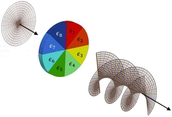
Figure 1.
The incident plane wave transformation into OAM carrying wave by the proposed ferroelectric lens.
For the proposed ferroelectric lens, the permittivity value changes with a constant step , i.e.,
where N—is the number of separate electrode’s sections.
Each mode of the wave carrying OAM characterized by a value of integer number l. The value of l determines the number of [0; 2] intervals of angular phase distribution in the lens aperture plane while its sign determines the direction of helical wavefront rotation. This condition determines requirements to ferroelectric material properties such as tunability factor (K = (E = 0)/(E)). The value of the tunability factor required for the formation of a certain mode can be determined as
where is the wavelength in free space, d is the thickness of the ferroelectric layer and —permittivity of ferroelectric ceramic at E = 0.
Therefore, for certain mode, the value of can be found from a condition that the maximal angular phase difference at the aperture of the lens is equal to 2, i.e.,
The eight section (N = 8) ferroelectric plate with a stepped distribution of permittivity is schematically presented in Figure 1. OAM carrying wave with the mode number l = ±1 will be formed by the lens if the permittivity step value corresponds to the phase shift difference between adjacent sections = 45. The conversion of the incident plane wave into OAM wave with l = +1, −1 corresponds to the angular distribution of the control electric field from to 0 V/m applied clockwise and counterclockwise, respectively. In the case of OAM mode numbers l = ±2, ±3... the value must be increased up to 90, 135 etc. The highest OAM mode (with number ) that can be formed by the lens depends on the tunability of ferroelectric ceramic, its thickness and N value. As known from [20,21] the theoretical limit of the highest mode which can be formed by discrete radiation sources is determined by = . However, it was observed that modes with l close N/2 demonstrate radiation patterns with ripples of the main beam [20]. These ripples increase and lead to the main beam destruction with a further increase of l. In turn, tunability K and ceramic thickness define the maximal value of that can be obtained. The radiation pattern of the circular lens in the condition of uniform amplitude and phase distribution at the aperture (l = 0) can be found using the approximation of circular aperture [22]:
where a—aperture radius, k—wavenumber, —radial distance, —azimuthal angle and —polar angle.
In the case of discrete increase of the phase angular distribution with step Equation (4) can be transformed to:
Note that in Equation (5) the wave attenuation in the ferroelectric plate and the wave spillover are neglect. These assumptions are valid for the estimations of the lens parameters at the first stages of its elaboration. The influence of these factors on the lens performance can be taken into account during a full-wave simulation.
Using Equation (5) the radiation patterns corresponded to different OAM waves (l = +1; +2; +3) were obtained and presented in Figure 2. The phase distributions of corresponded waves were calculated in the plane parallel to the lens aperture at the distance of 100 wavelengths and presented in Figure 2. One can conclude that the phase distribution demonstrates a spiral character in accordance with the mode number. It is also can be observed that increasing of l leads to an increase in angular ripples of the main beam directivity (see Figure 2b,d,f). Due to the lens symmetry, the change of the sign of l affects only the direction of the spiral phase distribution. Hence, the obtained results confirm that an 8-sectional ferroelectric lens provides the possibility of electrical switching between 6 OAM modes with |l| = 1, 2, 3.
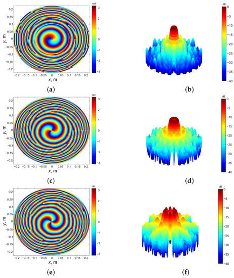
Figure 2.
Phase-front distributions and radiation patterns of different OAM modes l = +1 (a,b); l = +2 (c,d); l = +3 (e,f) formed by lens with N = 8.
3. Experimental Part
3.1. Prototype Description
To confirm the proposed OAM-wave formation approach a prototype with an operating frequency of 60 GHz was manufactured. It consists of two ferroelectric plates of barium strontium titanate with a surface area of 48 × 60 mm, and a thickness of 1 mm. The use of double plate design allows the decreasing value of the control electric voltage applied to each ferroelectric plate. The ferroelectric ceramic used to manufacture the prototype was produced by Ceramics Co. Ltd. (Saint Petersburg, Russia). It consists of a mixture of previously synthesized BaTiO and SrTiO powders (in a proportion of 55/45), and 40 wt.% linear dielectric materials (MgTiO, MgO). The density of the ceramic was 5.1 g/cm, the dielectric constant was , dielectric loss () was 0.015–0.02 at 60 GHz and the tunability factor K = 1.8 at 10 V/mm.
To achieve the radiotransparency of lens electrodes they should be made from a high-resistive material. The radiotransparency requires thin-film material with high surface resistivity. To simplify the prototype manufacturing process, graphite spray (GRAPHIT 33, CRC Industries) was used to form both the control and ground electrodes. It was experimentally observed that a graphite layer with a thickness of ∼10 m has a surface resistance of 1–2 kOhm/square and insertion loss about of 2 dB at 60 GHz.
The linear dielectric plates of quarter-wavelength thickness at 60 GHz should be used to match the impedances of the ferroelectric plates and free space. The glass-ceramic plates of 0.4 mm thickness (ST-50 type, JSC “Zavod Sytal”, Vladimir, Ukraine) were used as matching layers in the prototype. The glass-ceramic consists of SiO—60.5 wt.%, AlO—13.5 wt.%, CaO—8.5 wt.%, MgO—7.5 wt.% and TiO—10 wt.%. The real part of its dielectric permittivity was ∼10 and density was 2.65 g/cm.
The schematic of the lens construction and photo of the prototype are presented in Figure 3.
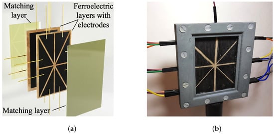
Figure 3.
Exploded-view—(a) and photo (matching layer removed)—(b) of tunable ferroelectric lens prototype.
3.2. Calculation and Simulation
To estimate the influence of the ferroelectric lens on the primary horn antenna radiation pattern, the 2-D electromagnetic simulation was performed by Comsol Multiphysics software (RF module). The calculation area was limited to a semi-circle with a radius of 15 at 60 GHz with the “Far-Field Calculation” boundary condition. The horn antenna with a length of 46 mm and aperture dimension of 30 mm was used as the primary antenna (the circular horn antenna with equal dimensions was used during the experimental investigation), placed in the center of the calculation area. The lens model consisted of a ferroelectric plate with dimensions 48 × 2 mm and matching layers of linear dielectric with dimensions of 48 × 0.4 mm was placed at a distance of 5 mm from the horn aperture. The simulated radiation pattern is presented in Figure 4a.
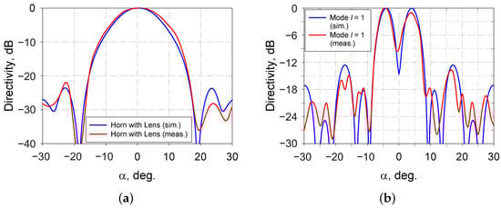
Figure 4.
Comparison of the simulated and measured beam of a horn with mode with l = 0 (a); comparison of the simulated and measured beam of mode with l = +1 (b).
To estimate the main beam shape of the radiation pattern, we used the far-field calculation based on the Fourier transform of the field at the lens aperture. This calculation method is well-established and efficient, especially for planar aperture antennas with dimensions larger than several wavelengths [23,24].
For calculation, we used a rectangular area as the lens aperture with a uniform amplitude distribution. The aperture area was divided into 8 angular sections (in accordance with the electrode topology) with corresponded initial phase values. These values were calculated according to the variation of ferroelectric plate permittivity under the applied control electric field. We should note that this simple model did not include the effects of mismatching of the ferroelectric plate and spillover of the primary antenna radiation and was investigated to provide the main beam shape. The calculated radiation pattern corresponded to OAM wave with is presented in Figure 4b.
3.3. Experimental Results
Experimental measurements of the ferroelectric lens prototype were performed in a microwave chamber. A horn antenna with an aperture diameter of 30 mm was used as a source of 60 GHz quasi-plane wave for lens irradiation. The receiver probe antenna was placed at a ∼20 cm distance from the lens aperture, which corresponds to the far-field condition for the 60 GHz radiation. The probe antenna was placed on a two-dimensional scanning system. The amplitude and phase of the radiated waves were measured by a vector network analyzer (VNA). The scanning and measurement routine was controlled by software running on a laptop. The control voltage was applied to the lens due to the laboratory voltage source connected to a self-made voltage-up conversion device. The control voltage for each controllable section of the lens prototype was separated due to the resistive divider.
The angular gradient of the control voltage in the range of 0–5 kV was formed to provide OAM-wave mode with l = +1. The control voltage magnitude is relatively high. However, there are several ways to decrease this value. The first of them is to use a ferroelectric ceramic with higher nonlinearity. Another is using a more complicated multilayer structure where the control voltage is applied to each layer individually. For example, a multilayer structure consisting of ten layers allows decreasing control voltage amplitude from 5 kV to ∼250 V. Please note that ferroelectric materials with higher dielectric permittivity and tunability values allow using ferroelectric thick films multilayer structures. Furthermore, increasing the frequency of operation will reduce the thickness of the ferroelectric layer, hence the control voltage. For example, a similar prototype device operating at 100 GHz will require control voltage with nearly twice a smaller amplitude. The total insertion loss of the lens prototype was about 12 dB. Please note that such a high value is due to the graphite electrodes used in the lens prototype construction. Possible use of thin/thick film high-resistive electrodes can decrease this value down to 5 dB. For example, indium tin oxide (ITO) is suitable because its surface resistance is up to 10 MOhm/square [25]. Resistive alloys such as silicides of chromium, nickel, iron, and binary and ternary systems on their base are perspective materials for transparent electrodes. A wide range of thin-film surface resistivity is achieved by the variation of Si concentration from 15% to 95% in the resistive alloys. These materials are usually used for thin-film resistors manufacturing.
Figure 5 presents measured amplitude and spatial phase distribution at a distance of ∼40 (∼20 cm) from the FE lens on the area of 70 × 70 mm. One can conclude that the central part of the measured phase-front demonstrates a spiral form. Around the point, with x = 0 and y = 0 (this point lies on the optical axis of the FE lens), the measured phase rises in the clockwise direction from 0 to 2 rad. Such a phase distribution corresponds to a phase-front of the OAM wave with l = +1.
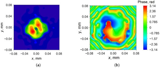
Figure 5.
Measured amplitude distribution—(a) and phase-front—(b) of the OAM wave with l = +1 formed by prototype.
The comparison of far-field radiation patterns measurements and calculation results for modes l = 0 and l = +1 are presented in Figure 4a,b, respectively. For convenience, due to the axial symmetry of the horn radiation pattern, only the horizontal cross-section of the radiation pattern is presented in Figure 4. The results demonstrate that the field intensity has a local minimum at the beam axis at l = +1. This characteristic feature confirms the formation of the electromagnetic wave with nonzero OAM by the proposed electrically tunable lens. Please note that electrode film thickness inhomogeneity can explain the asymmetry of the main beam of the measured radiation pattern.
4. Discussion and Conclusions
A method to form electromagnetic waves with nonzero OAM using an electrically tunable ferroelectric lens was proposed, and its applicability was experimentally demonstrated. The main advantages of the proposed method over the already existing methods (SPP, metasurfaces, etc.) are the simplicity of design, electrical control over the OAM modes formation, and the possibility to operate in the millimeter wavelengths. The ferroelectric lens construction to form nonzero OAM waves and its principle of operation were presented. The special discrete topology of high-resistive thin/thick film electrodes is proposed and analyzed. Correlation between film electrodes topology and a maximal number of OAM modes that can be formed by the lens is described. The device prototype based on ferroelectric BaSrTiO material was designed, manufactured and measured at a frequency of 60 GHz. Amplitude distribution and phase-front of the OAM wave with l= +1 formed by prototype were measured. Experimental results confirm the effectiveness of the proposed method.
Arguably, the value of control voltage used in the presented prototype is relatively high and this could be considered to be an obstacle for its practical implementation. A way around this challenge is to use a multilayer ferroelectric structure with individual voltage control [26]. Additionally, to improve the device performance (i.e., insertion loss, responsivity (to control voltage), etc.), a further optimal material selection combined with detecting and separating the formed OAM-wave modes investigation is required.
Nevertheless, the proposed method is a steppingstone toward the enhancement of the wireless communication data transfer rate.
Author Contributions
Conceptualization, A.A., R.P. and A.K.; modeling, R.P., A.A.; prototype manufacturing, A.T., R.P.; investigation, A.A., P.K.P.; data analysis, A.A., R.P.; writing—review and editing, all authors; supervision, A.A. All authors have read and agreed to the published version of the manuscript.
Funding
This work is supported by the Russian Science Foundation under grant 18-79-10156. Peter K. Petrov acknowledges the support from the Henry Royce Institute through EPSRC grant EP/R00661X/1.
Institutional Review Board Statement
Not applicable.
Informed Consent Statement
Not applicable.
Data Availability Statement
The data that support the findings of this study are available from A. Altynnikov upon reasonable request.
Conflicts of Interest
The authors declare no conflict of interest.
References
- Lee, D.; Sasaki, H.; Fukumoto, H.; Yagi, Y.; Shimizu, T. An evaluation of orbital angular momentum multiplexing technology. Appl. Sci. 2019, 9, 1729. [Google Scholar] [CrossRef]
- Hu, T.; Wang, Y.; Liao, X.; Zhang, J.; Song, Q. OFDM-OAM modulation for future wireless communications. IEEE Access 2019, 7, 59114–59125. [Google Scholar] [CrossRef]
- Chen, X.; Xue, W.; Shi, H.; Yi, J.; Wei, E.I. Orbital angular momentum multiplexing in highly reverberant environments. IEEE Microw. Wirel. Compon. Lett. 2019, 30, 112–115. [Google Scholar] [CrossRef]
- Cheng, L.; Hong, W.; Hao, Z.C. Generation of electromagnetic waves with arbitrary orbital angular momentum modes. Sci. Rep. 2014, 4, 4814. [Google Scholar] [CrossRef]
- Allen, B.; Pelham, T.; Wu, Y.; Drysdale, T.; Isakov, D.; Gamlath, C.; Stevens, C.J.; Hilton, G.; Beach, M.A.; Grant, P.S. Experimental evaluation of 3D printed spiral phase plates for enabling an orbital angular momentum multiplexed radio system. R. Soc. Open Sci. 2019, 6, 191419. [Google Scholar] [CrossRef] [PubMed]
- Tamburini, F.; Mari, E.; Thidé, B.; Barbieri, C.; Romanato, F. Experimental verification of photon angular momentum and vorticity with radio techniques. Appl. Phys. Lett. 2011, 99, 204102. [Google Scholar] [CrossRef]
- Tamburini, F.; Mari, E.; Sponselli, A.; Thidé, B.; Bianchini, A.; Romanato, F. Encoding many channels on the same frequency through radio vorticity: First experimental test. New J. Phys. 2012, 14, 033001. [Google Scholar] [CrossRef]
- Shi, H.; Wang, L.; Peng, G.; Chen, X.; Li, J.; Zhu, S.; Zhang, A.; Xu, Z. Generation of multiple modes microwave vortex beams using active metasurface. IEEE Antennas Wirel. Propag. Lett. 2018, 18, 59–63. [Google Scholar] [CrossRef]
- Ji, C.; Song, J.; Huang, C.; Wu, X.; Luo, X. Dual-band vortex beam generation with different OAM modes using single-layer metasurface. Opt. Express 2019, 27, 34–44. [Google Scholar] [CrossRef] [PubMed]
- Yu, S.; Li, L.; Shi, G.; Zhu, C.; Zhou, X.; Shi, Y. Design, fabrication, and measurement of reflective metasurface for orbital angular momentum vortex wave in radio frequency domain. Appl. Phys. Lett. 2016, 108, 121903. [Google Scholar] [CrossRef]
- Chen, M.L.; Jiang, L.J.; Sha, W.E. Artificial perfect electric conductor-perfect magnetic conductor anisotropic metasurface for generating orbital angular momentum of microwave with nearly perfect conversion efficiency. J. Appl. Phys. 2016, 119, 064506. [Google Scholar] [CrossRef]
- Yang, T.; Yang, D.; Wang, B.; Hu, J. Experimentally Validated, Wideband, Compact, OAM Antennas Based on Circular Vivaldi Antenna Array. Prog. Electromagn. Res. 2018, 80, 211–219. [Google Scholar] [CrossRef]
- Qin, F.; Li, L.; Liu, Y.; Cheng, W.; Zhang, H. A four-mode OAM antenna array with equal divergence angle. IEEE Antennas Wirel. Propag. Lett. 2019, 18, 1941–1945. [Google Scholar] [CrossRef]
- Deng, C.; Chen, W.; Zhang, Z.; Li, Y.; Feng, Z. Generation of OAM radio waves using circular Vivaldi antenna array. Int. J. Antennas Propag. 2013, 2013, 607–610. [Google Scholar] [CrossRef]
- Yan, Y.; Xie, G.; Lavery, M.P.; Huang, H.; Ahmed, N.; Bao, C.; Ren, Y.; Cao, Y.; Li, L.; Zhao, Z.; et al. High-capacity millimetre-wave communications with orbital angular momentum multiplexing. Nat. Commun. 2014, 5, 4876. [Google Scholar] [CrossRef] [PubMed]
- Mohammadi, S.M.; Daldorff, L.K.; Forozesh, K.; Thidé, B.; Bergman, J.E.; Isham, B.; Karlsson, R.; Carozzi, T.D. Orbital angular momentum in radio: Measurement methods. Radio Sci. 2010, 45. [Google Scholar] [CrossRef]
- Zhang, K.; Wang, Y.; Yuan, Y.; Burokur, S.N. A review of orbital angular momentum vortex beams generation: From traditional methods to metasurfaces. Appl. Sci. 2020, 10, 1015. [Google Scholar] [CrossRef]
- Vasnetsov, M.V.; Torres, J.P.; Petrov, D.V.; Torner, L. Observation of the orbital angular momentum spectrum of a light beam. Opt. Lett. 2003, 28, 2285–2287. [Google Scholar] [CrossRef] [PubMed]
- Nenasheva, E.A.; Kartenko, N.F.; Gaidamaka, I.M.; Trubitsyna, O.N.; Redozubov, S.S.; Dedyk, A.I. and Kanareykin, A.D. Low loss microwave ferroelectric ceramics for high power tunable devices. J. Eur. Ceram. Soc. 2010, 30, 395–400. [Google Scholar] [CrossRef]
- Thidé, B.; Then, H.; Sjöholm, J.; Palmer, K.; Bergman, J.; Carozzi, T.D.; Istomin, Y.N.; Ibragimov, N.H.; Khamitova, R. Utilization of photon orbital angular momentum in the low-frequency radio domain. Phys. Rev. Lett. 2007, 99, 087701. [Google Scholar] [CrossRef]
- Mohammadi, S.M.; Daldorff, L.K.; Bergman, J.E.; Karlsson, R.L.; Thidé, B.; Forozesh, K.; Carozzi, T.D.; Isham, B. Orbital angular momentum in radio—A system study. IEEE Trans. Antennas Propag. 2009, 58, 565–572. [Google Scholar] [CrossRef]
- Stutzman, W.; Thiele, G. Antenna Theory and Design, 2nd ed.; John Wiley & Sons: Hoboken, NJ, USA, 2012. [Google Scholar]
- Balanis, C. Antenna Theory: Analysis and Design, 4th ed.; John Wiley & Sons: Hoboken, NJ, USA, 2015. [Google Scholar]
- Shen, F.; Wang, A. Fast-Fourier-transform based numerical integration method for the Rayleigh-Sommerfeld diffraction formula. Appl. Opt. 2006, 45, 1102–1110. [Google Scholar] [CrossRef] [PubMed]
- Minami, T. Present status of transparent conducting oxide thin-film development for Indium-Tin-Oxide (ITO) substitutes. Thin Solid Films 2008, 516, 5822–5828. [Google Scholar] [CrossRef]
- Ptashnik, S.V.; Mikhailov, A.K.; Yastrebov, A.V.; Petrov, P.K.; Liu, W.; Alford, N.M.; Hirsch, S.; Kozyrev, A.B. Ferroelectric thin film acoustic devices with electrical multiband switching ability. Sci. Rep. 2017, 7, 15289. [Google Scholar] [CrossRef] [PubMed]
Publisher’s Note: MDPI stays neutral with regard to jurisdictional claims in published maps and institutional affiliations. |
© 2021 by the authors. Licensee MDPI, Basel, Switzerland. This article is an open access article distributed under the terms and conditions of the Creative Commons Attribution (CC BY) license (https://creativecommons.org/licenses/by/4.0/).