
The Role of Electric Pressure/Stress Suppressing Pinhole Defect on Coalescence Dynamics of Electrified Droplet

 ,
,  ,
, 
Abstract
1. Introduction
2. Materials and Methods
2.1. Materials and Experimental Setup for Visulization of Droplet Coalescence
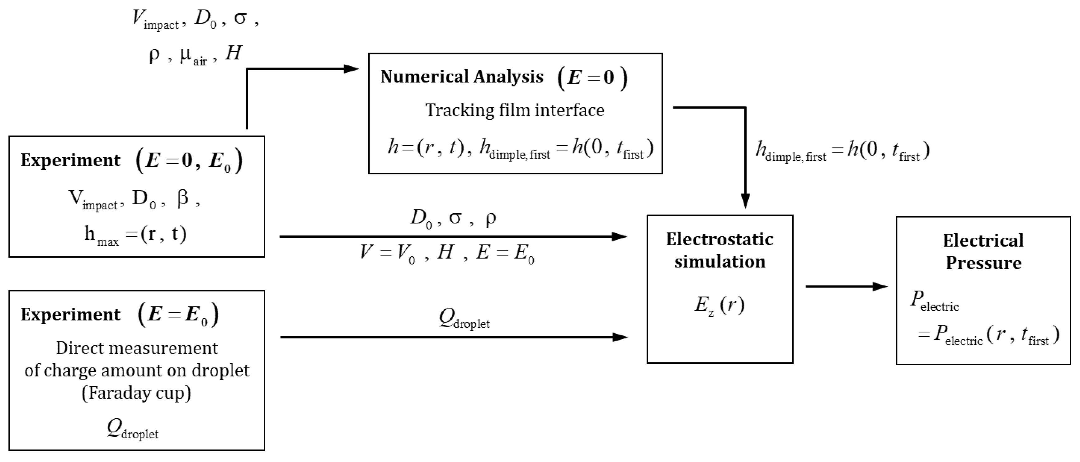
2.2. Measurement of Charge Amount on Droplet ()
3. Numerical Analysis
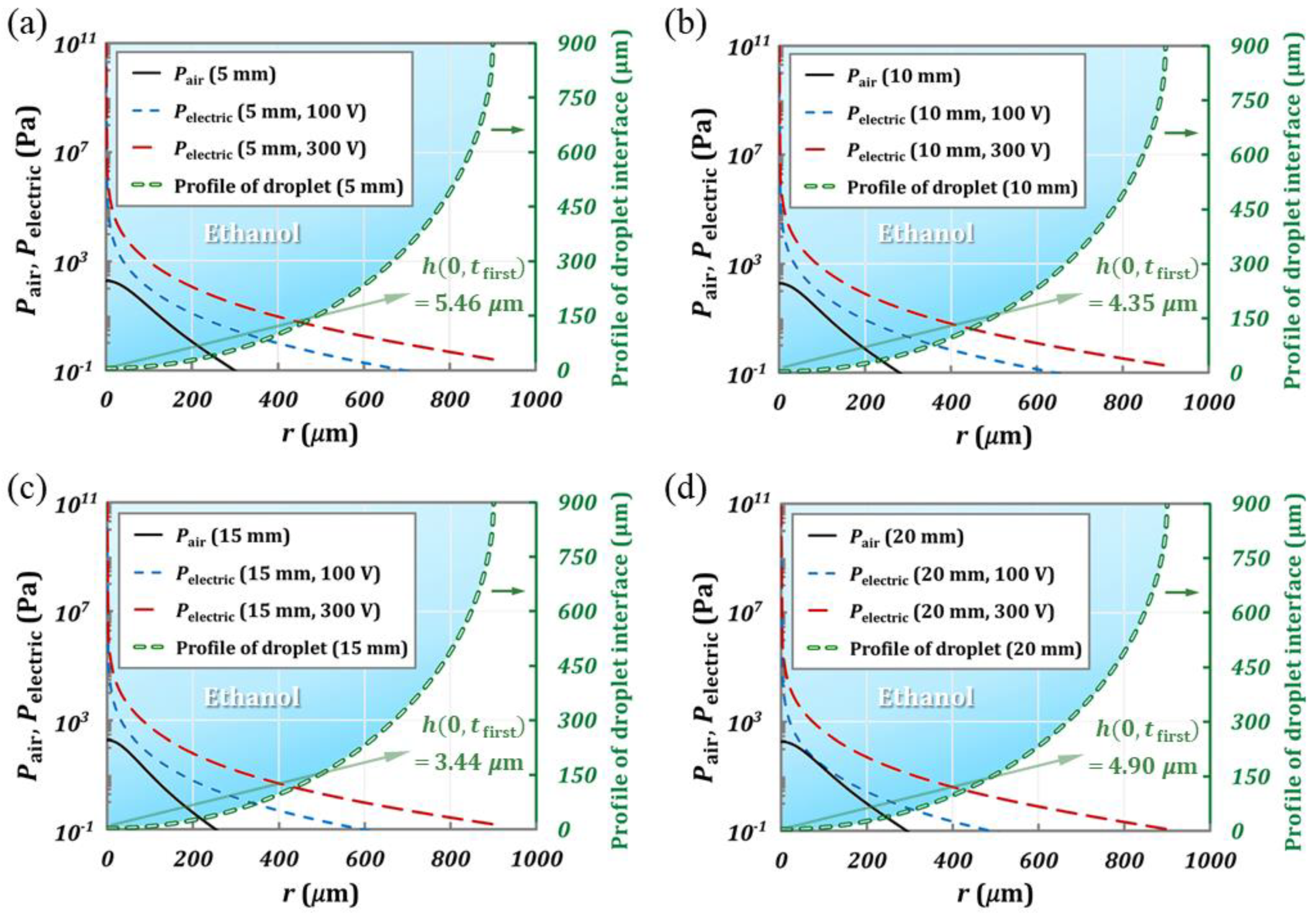
3.1. Electric Pressure ()
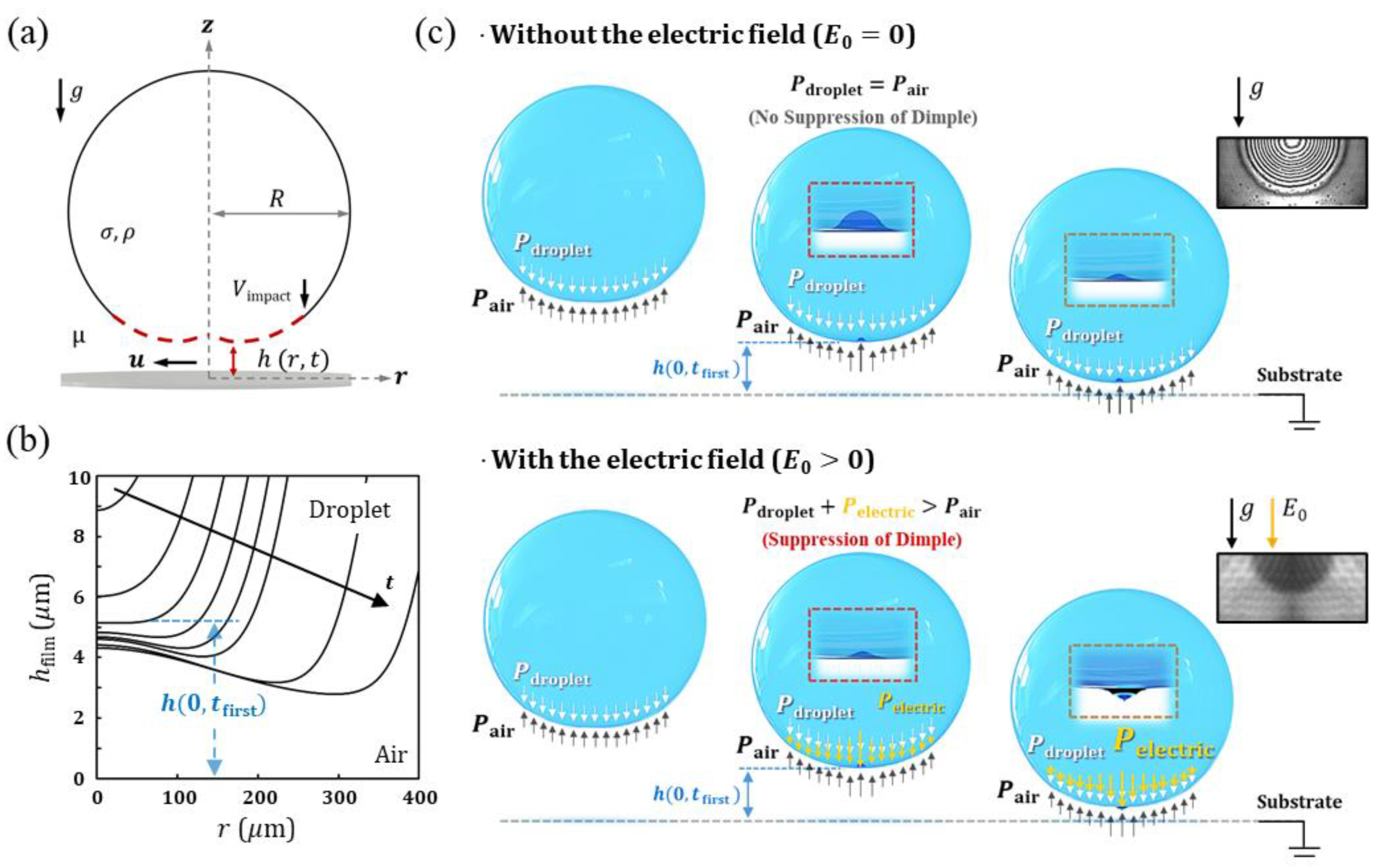
3.1.1. The Gap Height When a Dimple Is Firstly Formed
- Governing Equations
- Initial and boundary conditions for tracking film interface
- Nondimensionalization
- Tracking of Film Profiles and Height of Dimple Formation
3.1.2. Electrostatic Simulation for Distribution of Electric field
- Electric Pressure ()
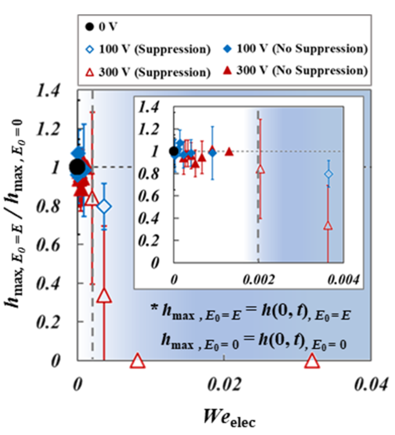
3.2. Electric Weber Number ()
4. Result and Discussion
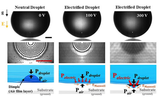
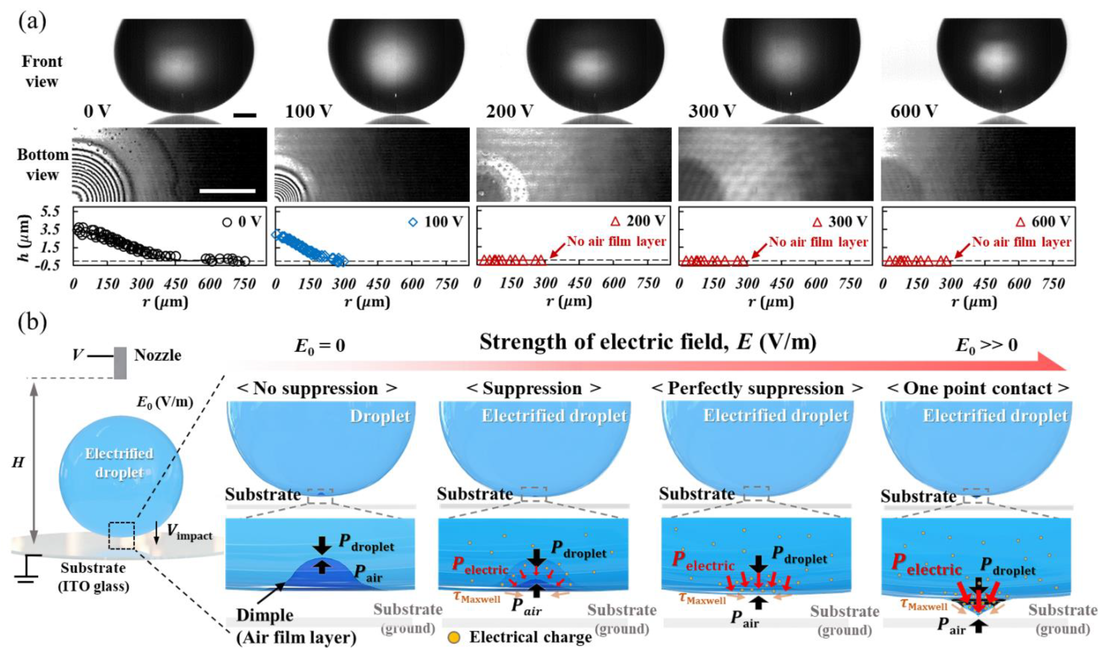
4.1. Coalescence Dynamic of Electrified Droplet
4.2. Suppression of Dimple of Electrified Droplet
4.3. Electric Pressure in a Coalescence of an Electrified Droplet
5. Conclusions
Supplementary Materials
Author Contributions
Funding
Institutional Review Board Statement
Informed Consent Statement
Data Availability Statement
Conflicts of Interest
References
- Klyuzhin, I.S.; Ienna, F.; Roeder, B.; Wexler, A.; Pollack, G.H. Persisting water droplets on water surfaces. J. Phys. Chem. B 2010, 114, 14020–14027. [Google Scholar] [CrossRef]
- Chen, L.; Xiao, Z.; Chan, P.C.; Lee, Y.-K.; Li, Z. A comparative study of droplet impact dynamics on a dual-scaled superhydrophobic surface and lotus leaf. Appl. Surf. Sci. 2011, 257, 8857–8863. [Google Scholar] [CrossRef]
- Ju, J.; Bai, H.; Zheng, Y.; Zhao, T.; Fang, R.; Jiang, L. A multi-structural and multi-functional integrated fog collection system in cactus. Nat. Commun. 2012, 3, 1–6. [Google Scholar] [CrossRef]
- Tan, Y.-C.; Ho, Y.L.; Lee, A.P. Droplet coalescence by geometrically mediated flow in microfluidic channels. Microfluid. Nanofluid. 2007, 3, 495–499. [Google Scholar] [CrossRef]
- Christopher, G.; Bergstein, J.; End, N.; Poon, M.; Nguyen, C.; Anna, S.L. Coalescence and splitting of confined droplets at microfluidic junctions. Lab A Chip 2009, 9, 1102–1109. [Google Scholar] [CrossRef]
- Zagnoni, M.; Baroud, C.N.; Cooper, J.M. Electrically initiated upstream coalescence cascade of droplets in a microfluidic flow. Phys. Rev. E 2009, 80, 046303. [Google Scholar] [CrossRef]
- Ihnen, A.C.; Petrock, A.M.; Chou, T.; Fuchs, B.E.; Lee, W.Y. Organic nanocomposite structure tailored by controlling droplet coalescence during inkjet printing. ACS Appl. Mater. Interfaces 2012, 4, 4691–4699. [Google Scholar] [CrossRef]
- Lee, M.W.; Kim, N.Y.; Chandra, S.; Yoon, S.S. Coalescence of sessile droplets of varying viscosities for line printing. Int. J. Multiph. Flow 2013, 56, 138–148. [Google Scholar] [CrossRef]
- Castrejón-Pita, J.; Kubiak, K.; Castrejón-Pita, A.; Wilson, M.; Hutchings, I.M. Mixing and internal dynamics of droplets impacting and coalescing on a solid surface. Phys. Rev. E 2013, 88, 023023. [Google Scholar] [CrossRef]
- Yang, X.; Chhasatia, V.H.; Sun, Y. Oscillation and recoil of single and consecutively printed droplets. Langmuir 2013, 29, 2185–2192. [Google Scholar] [CrossRef]
- Sarojini KG, K.; Dhar, P.; Varughese, S.; Das, S.K. Coalescence dynamics of PEDOT:PSS droplets impacting at offset on substrates for inkjet printing. Langmuir 2016, 32, 5838–5851. [Google Scholar] [CrossRef]
- Cao, X.; Ye, Y.; Tang, Q.; Chen, E.; Jiang, Z.; Pan, J.; Guo, T. Numerical analysis of droplets from multinozzle inkjet printing. J. Phys. Chem. Lett. 2020, 11, 8442–8450. [Google Scholar] [CrossRef] [PubMed]
- Ko, G.H.; Ryou, H.S. Droplet collision processes in an inter-spray impingement system. J. Aerosol Sci. 2005, 36, 1300–1321. [Google Scholar] [CrossRef]
- Kim, S.; Lee, D.J.; Lee, C.S. Modeling of binary droplet collisions for application to inter-impingement sprays. Int. J. Multiph. Flow 2009, 35, 533–549. [Google Scholar] [CrossRef]
- Damak, M.; Mahmoudi, S.R.; Hyder, M.N.; Varanasi, K.K. Enhancing droplet deposition through in-situ precipitation. Nat. Commun. 2016, 7, 1–9. [Google Scholar] [CrossRef] [PubMed]
- Finotello, G.; Padding, J.T.; Deen, N.G.; Jongsma, A.; Innings, F.; Kuipers, J. Effect of viscosity on droplet-droplet collisional interaction. Phys. Fluids 2017, 29, 067102. [Google Scholar] [CrossRef]
- Li, E.; Vakarelski, I.U.; Thoroddsen, S.T. Probing the nanoscale: The first contact of an impacting drop. J. Fluid Mech. 2015, 785. [Google Scholar] [CrossRef]
- Josserand, C.; Thoroddsen, S.T. Drop impact on a solid surface. Annu. Rev. Fluid Mech. 2016, 48, 365–391. [Google Scholar] [CrossRef]
- De Ruiter, J.; Lagraauw, R.; Van Den Ende, D.; Mugele, F. Wettability-independent bouncing on flat surfaces mediated by thin air films. Nat. Phys. 2015, 11, 48. [Google Scholar] [CrossRef]
- Ding, Z.; Xing, R.; Fu, Q.; Ma, D.; Han, Y. Patterning of pinhole free small molecular organic light-emitting films by ink-jet printing. Org. Electron. 2011, 12, 703–709. [Google Scholar] [CrossRef]
- Saha, J.K.; Bukke, R.N.; Mude, N.N.; Jang, J. Significant improvement of spray pyrolyzed ZnO thin film by precursor optimization for high mobility thin film transistors. Sci. Rep. 2020, 10, 1–11. [Google Scholar] [CrossRef] [PubMed]
- Meng, J.; Lau, C.H.; Xue, Y.; Zhang, R.; Cao, B.; Li, P. Compatibilizing hydrophilic and hydrophobic polymers via spray coating for desalination. J. Mater. Chem. A 2020, 8, 8462–8468. [Google Scholar] [CrossRef]
- Seong, B.; Hwang, S.; Jang, H.-S.; Lee, H.; Kim, J.; Nguyen, V.D.; Cho, D.-H.; Lin, L.; Byun, D. A hybrid aerodynamic and electrostatic atomization system for enhanced uniformity of thin film. J. Electrost. 2017, 87, 93–101. [Google Scholar] [CrossRef]
- Qin, H.; Wei, C.; Dong, J.; Lee, Y.-S. Direct printing and electrical characterization of conductive micro-silver tracks by alternating current-pulse modulated electrohydrodynamic jet printing. J. Manuf. Sci. Eng. 2017, 139, 021008. [Google Scholar] [CrossRef]
- Shin, D.-Y.; Yoo, S.-S.; Song, H.-e.; Tak, H.; Byun, D. Electrostatic-force-assisted dispensing printing to construct high-aspect-ratio of 0.79 electrodes on a textured surface with improved adhesion and contact resistivity. Sci. Rep. 2015, 5, 16704. [Google Scholar] [CrossRef] [PubMed]
- Lee, H.; Seong, B.; Kim, J.; Jang, Y.; Byun, D. Direct alignment and patterning of silver nanowires by electrohydrodynamic jet printing. Small 2014, 10, 3918–3922. [Google Scholar] [CrossRef]
- Seong, B.; Chae, I.; Lee, H.; Nguyen, V.D.; Byun, D. Spontaneous self-welding of silver nanowire networks. Phys. Chem. Chem. Phys. 2015, 17, 7629–7633. [Google Scholar] [CrossRef]
- Guo, Q.; Mather, J.P.; Yang, P.; Boden, M.; Mather, P.T. Fabrication of polymeric coatings with controlled microtopographies using an electrospraying technique. PLoS ONE 2015, 10, e0129960. [Google Scholar] [CrossRef]
- Gao, F.; Yi, H.; Qi, L.; Qiao, R.; Deng, W. Weakly charged droplets fundamentally change impact dynamics on flat surfaces. Soft Matter 2019, 15, 5548–5553. [Google Scholar] [CrossRef]
- Bouwhuis, W.; Van der Veen, R.C.; Tran, T.; Keij, D.L.; Winkels, K.G.; Peters, I.R.; Van der Meer, D.; Sun, C.; Snoeijer, J.H.; Lohse, D. Maximal air bubble entrainment at liquid-drop impact. Phys. Rev. Lett. 2012, 109, 264501. [Google Scholar] [CrossRef]
- Mehdi-Nejad, V.; Mostaghimi, J.; Chandra, S. Air bubble entrapment under an impacting droplet. Phys. Fluids 2003, 15, 173–183. [Google Scholar] [CrossRef]
- San Lee, J.; Weon, B.M.; Je, J.H.; Fezzaa, K. How does an air film evolve into a bubble during drop impact? Phys. Rev. Lett. 2012, 109, 204501. [Google Scholar]
- De Ruiter, J.; Oh, J.M.; Van den Ende, D.; Mugele, F. Dynamics of collapse of air films in drop impact. Phys. Rev. Lett. 2012, 108, 074505. [Google Scholar] [CrossRef]
- Choi, D.; Lee, H.; Kang, I.S.; Lim, G.; Kim, D.S.; Kang, K.H. Spontaneous electrical charging of droplets by conventional pipetting. Sci. Rep. 2013, 3, 2037. [Google Scholar] [CrossRef]
- Lee, H.; Choi, D.; Kim, D.S.; Lim, G. Capacitive control of spontaneously induced electrical charge of droplet by electric field-assisted pipetting. Nano-Micro Lett. 2015, 7, 341–346. [Google Scholar] [CrossRef] [PubMed][Green Version]
- Chan, D.Y.; Klaseboer, E.; Manica, R. Theory of non-equilibrium force measurements involving deformable drops and bubbles. Adv. Colloid Interface Sci. 2011, 165, 70–90. [Google Scholar] [CrossRef]
- Klaseboer, E.; Manica, R.; Chan, D.Y. Universal behavior of the initial stage of drop impact. Phys. Rev. Lett. 2014, 113, 194501. [Google Scholar] [CrossRef]
- Lee, S.; Denn, M.; Crochet, M.; Metzner, A. Compressive flow between parallel disks:: I. Newtonian fluid with a transverse viscosity gradient. J. Non-Newton. Fluid Mech. 1982, 10, 3–30. [Google Scholar] [CrossRef]
- Klaseboer, E.; Chevaillier, J.P.; Gourdon, C.; Masbernat, O. Film drainage between colliding drops at constant approach velocity: Experiments and modeling. J. Colloid Interface Sci. 2000, 229, 274–285. [Google Scholar] [CrossRef]
- De Ruiter, J.; Van den Ende, D.; Mugele, F. Air cushioning in droplet impact. II. Experimental characterization of the air film evolution. Phys. Fluids 2015, 27, 012105. [Google Scholar] [CrossRef]
- Hendrix, M.H.; Bouwhuis, W.; Van der Meer, D.; Lohse, D.; Snoeijer, J.H. Universal mechanism for air entrainment during liquid impact. J. Fluid Mech. 2016, 789, 708–725. [Google Scholar] [CrossRef]
- Eow, J.S.; Ghadiri, M.; Sharif, A. Deformation and break-up of aqueous drops in dielectric liquids in high electric fields. J. Electrost. 2001, 51, 463–469. [Google Scholar] [CrossRef]
- Mousavichoubeh, M.; Shariaty-Niassar, M.; Ghadiri, M. The effect of interfacial tension on secondary drop formation in electro-coalescence of water droplets in oil. Chem. Eng. Sci. 2011, 66, 5330–5337. [Google Scholar] [CrossRef]
- Thoroddsen, S.; Takehara, K. The coalescence cascade of a drop. Phys. Fluids 2000, 12, 1265–1267. [Google Scholar] [CrossRef]
- Ristenpart, W.; Bird, J.; Belmonte, A.; Dollar, F.; Stone, H. Non-coalescence of oppositely charged drops. Nature 2009, 461, 377. [Google Scholar] [CrossRef]
- Wang, J.; Wang, B.; Qiu, H. Coalescence and breakup of oppositely charged droplets. Sci. Rep. 2014, 4, 7123. [Google Scholar] [CrossRef] [PubMed]
- Bird, J.C.; Ristenpart, W.D.; Belmonte, A.; Stone, H.A. Critical angle for electrically driven coalescence of two conical droplets. Phys. Rev. Lett. 2009, 103, 164502. [Google Scholar] [CrossRef]


| Applied Voltage | Dripping Height | |||||||
|---|---|---|---|---|---|---|---|---|
| 5 mm | 10 mm | 15 mm | 20 mm | |||||
| V | V/m | nC | V/m | nC | V/m | nC | V/m | nC |
| 100 | 20,000 | 0.0060 | 10,000 | 0.0052 | 666.67 | 0.0043 | 5000 | 0.0029 |
| 300 | 60,000 | 0.0185 | 30,000 | 0.0156 | 20,000 | 0.0137 | 15,000 | 0.0125 |
| Applied Voltage | Dripping Height | |||||||
|---|---|---|---|---|---|---|---|---|
| 5 mm | 10 mm | 15 mm | 20 mm | |||||
| V | V/m | nC | V/m | nC | V/m | nC | V/m | nC |
| 100 | 20,000 | 0.0081 | 10,000 | 0.0067 | 666.67 | 0.0056 | 5000 | 0.0052 |
| 300 | 60,000 | 0.0252 | 30,000 | 0.0212 | 20,000 | 0.0186 | 15,000 | 0.0163 |
| Liquid | Dripping Height | |||||||
|---|---|---|---|---|---|---|---|---|
| 5 mm | 10 mm | 15 mm | 20 mm | |||||
| - | ||||||||
| - | (-) | () | (-) | () | (-) | () | (-) | () |
| Ethanol | 4.21 | 5.16 | 10.41 | 4.35 | 17.50 | 3.44 | 24.27 | 4.90 |
| DI water | 0.82 | 3.89 | 2.57 | 3.69 | 4.43 | 3.44 | 6.20 | 3.29 |
Publisher’s Note: MDPI stays neutral with regard to jurisdictional claims in published maps and institutional affiliations. |
© 2021 by the authors. Licensee MDPI, Basel, Switzerland. This article is an open access article distributed under the terms and conditions of the Creative Commons Attribution (CC BY) license (https://creativecommons.org/licenses/by/4.0/).
Share and Cite
Lee, J.; Esmaili, E.; Kang, G.; Seong, B.; Kang, H.; Kim, J.; Jung, S.; Kim, H.; Byun, D. The Role of Electric Pressure/Stress Suppressing Pinhole Defect on Coalescence Dynamics of Electrified Droplet. Coatings 2021, 11, 503. https://doi.org/10.3390/coatings11050503
Lee J, Esmaili E, Kang G, Seong B, Kang H, Kim J, Jung S, Kim H, Byun D. The Role of Electric Pressure/Stress Suppressing Pinhole Defect on Coalescence Dynamics of Electrified Droplet. Coatings. 2021; 11(5):503. https://doi.org/10.3390/coatings11050503
Chicago/Turabian StyleLee, Jaehyun, Ehsan Esmaili, Giho Kang, Baekhoon Seong, Hosung Kang, Jihoon Kim, Sunghwan Jung, Hyunggun Kim, and Doyoung Byun. 2021. "The Role of Electric Pressure/Stress Suppressing Pinhole Defect on Coalescence Dynamics of Electrified Droplet" Coatings 11, no. 5: 503. https://doi.org/10.3390/coatings11050503
APA StyleLee, J., Esmaili, E., Kang, G., Seong, B., Kang, H., Kim, J., Jung, S., Kim, H., & Byun, D. (2021). The Role of Electric Pressure/Stress Suppressing Pinhole Defect on Coalescence Dynamics of Electrified Droplet. Coatings, 11(5), 503. https://doi.org/10.3390/coatings11050503