Article

Microstructure, Mechanical Properties and Tribological Behavior of Magnetron-Sputtered MoS2 Solid Lubricant Coatings Deposited under Industrial Conditions

1
Engineering Design and CAD, Universität Bayreuth, Universitätsstr. 30, 95447 Bayreuth, Germany
2
Materials Science & Engineering I, Friedrich-Alexander-Universität Erlangen-Nürnberg (FAU), Martensstr. 5, 91058 Erlangen, Germany
3
Interdisciplinary Center for Nanostructured Films (IZNF), Friedrich-Alexander-Universität Erlangen-Nürnberg (FAU), Cauerstr. 3, 91058 Erlangen, Germany
4
Interdisciplinary Center for Molecular Materials (ICMM) and Computer Chemistry Center (CCC), Friedrich-Alexander-Universität Erlangen-Nürnberg (FAU), Nägelsbachstr. 25, 91052 Erlangen, Germany
*
Author to whom correspondence should be addressed.
Coatings 2021, 11(4), 455; https://doi.org/10.3390/coatings11040455
Submission received: 21 March 2021 / Revised: 8 April 2021 / Accepted: 12 April 2021 / Published: 15 April 2021
(This article belongs to the Section Surface Characterization, Deposition and Modification)

Abstract

:
Depositing MoS2 coatings for industrial applications involves rotating the samples during the PVD magnetron sputtering process. Here, we show that a 3-fold substrate rotation, along a large target–substrate distance given by the deposition unit, introduces porosity inside the coatings. The mechanical properties and wear behavior strongly correlate with the degree of porosity, which, in turn, depends on the temperature and the rotational speed of the substrate. Ball-on-disk tests and nanoindentation wear experiments show a consistent change in tribological behavior; first, a compaction of the porous structure dominates, followed by wear of the compacted material. Compaction was the main contributor to the volume loss during the running-in process. Compared to a dense coating produced without substrate rotation, the initially porous coatings showed lower hardness and a distinct running-in behavior. Tribological lifetime experiments showed good lubrication performance after compaction.

1. Introduction

Tribologically efficient MoS2 coatings are mostly used in technical applications under extreme conditions where conventional lubricants such as oils and greases cannot be utilized. This includes applications in vacuum (e.g., space exploration), at high temperatures (e.g., hardening furnaces), at very low temperatures (e.g., cryopumps), in the presence of high-energy radiation (e.g., nuclear fusion reactors) or where product contamination by conventional lubricants is unacceptable (e.g., bearings in optical devices) [1,2]. Magnetron-sputtered MoS2 coatings are generally regarded as good solid lubricants for vacuum applications, where the microstructure shows the best tribological behavior [3,4]. The excellent tribological behavior, which is reflected in a very low coefficient of friction (COF) [5,6] and a low wear coefficient [7], is attributed to the layered structure of MoS2 [8].
MoS2 is composed of individual S-Mo-S lamellae, with the lamellae growing parallel (basal), vertically or randomly oriented with respect to the substrate. A basal orientation is generally seen as desirable, as this favors the easy sliding of individual lamellae from each other and is correlated with a longer lifetime of the coatings [9,10,11]. In the sputter deposition process, the microstructure of coatings, including transition metal dichalcogenides such as MoS2, can be influenced by changing the process parameters, such as temperature, pressure or bias voltage [12,13,14,15]. In addition, a significant influence of the target–substrate distance has also been evidenced, which has been attributed to the decreasing impact energy of the ions with increasing distance that negatively affects the film growth [16,17,18,19].
Industrial applications require evenly coated surfaces of components with complex shapes, which can only be achieved with 3-fold substrate rotation. While many published studies have been performed on MoS2 coatings without 3-fold substrate rotation, the properties of coatings specifically deposited under industrial conditions have, thus far, been less studied in the literature. The transferability of results from idealized studies to industrial applications, therefore, represents a real challenge.
The aim of this paper was to investigate and evaluate the influence of 3-fold substrate rotation on the microstructure, mechanical properties and tribological behavior of sputter-deposited MoS2 coatings and evaluate them compared to coatings deposited without substrate rotation. As a representative for a coating deposited under laboratory conditions (no substrate rotation, placed relatively close in front of the target), we used a preliminary work previously published in [20]. This coating showed very good tribological behavior. It was, therefore, the starting point for our research work and serves as a benchmark in terms of tribology. It should not be concealed that the target–substrate distance is four times higher for the coatings deposited with 3-fold substrate rotation than that for the coating without substrate rotation. This is due to the fact that the target–substrate distance cannot be varied at will due to technical restrictions in industrial deposition units but is rather predetermined by installations, etc. Tribological tests on the macroscale and on the microscale were performed to provide information about the friction and wear behavior and to identify correlations between both scales. Furthermore, the MoS2 coatings were analyzed using scanning electron microscopy (SEM) to assess the changes in morphology and chemical composition. Mechanical properties were investigated by nanoindentation.

2. Materials and Methods

2.1. Deposition Process and Specimens

For the investigations, MoS2 coatings were deposited on two types of flat specimens made of 100Cr6 bearing steel (1.3505, AISI 52100) with sample dimensions of Ø 30 mm × 5 mm and Ø 10 mm × 3 mm. Before the deposition process, the substrates were tempered and hardened to 62 ± 1 HRC. The mirror-polished roughness of the specimens was Ra ≈ 0.005 µm, measured by two-dimensional contacting profilometry (Taylor Hobson, PGI NOVUS, Leicester, UK) and analyzed according to DIN EN ISO 13565-1. Prior to the deposition process, the specimens were ultrasonically cleaned with acetone and isopropyl alcohol for 10 min each.
All MoS2 coatings investigated in this paper were deposited by magnetron sputtering in an industrial-scale physical vapor deposition unit (H-O-T Härte- und Oberflächentechnik, TT 300 K4, Nürnberg, Germany). A schematic view of the deposition unit is shown in Figure 1. Most importantly, this deposition unit allows for 3-fold substrate rotation during the process, which is key to uniformly coating non-flat parts. In order to study the influence of substrate rotation and the target–substrate distance, a reference sample was fabricated without any substrate rotation, based on previous work by Vierneusel et al. [20,21]. In this case, the substrate was simply fastened directly in front of the MoS2 target. For the three other coatings, which aimed at mimicking industrial processes, the substrates were placed into a 3-fold rotating charging rack and were coated with two MoS2 targets located on either side of the coating chamber (c.f. Figure 1). The targets were hot-pressed MoS2 powder with a purity of 99.5% and with dimensions of 260 mm × 163 mm (GfE Metalle und Materialien GmbH, Nürnberg, Germany).
The starting pressure for the PVD process was 2.5 × 10⁻³ Pa. For evacuating the deposition chamber, we used a powerful pumping unit consisting of a rotary vane pump, a Roots pump and a turbomolecular pump. No cryopump was used. The remaining atmosphere mainly consisted of residual water, but very small quantities of oxygen, nitrogen or carbon cannot be excluded. Before initiating deposition, the chamber was heated by an infrared emitter to the temperature specified in Table 1 and then held. The chamber temperature was measured and regulated using two temperature sensors placed in the door of the deposition unit. No direct substrate temperature measurement was carried out. The surface of the substrates was plasma etched for 15 min using an argon flow of 500 sccm and a pulsed DC bias voltage (pulse frequency of 40 kHz, positive pulse duration of 5 µs) of −500 V.
The relevant deposition process parameters are listed in Table 1. One of the investigated MoS2 coatings was deposited without substrate rotation (NoRot). RefRot was deposited with 3-fold substrate rotation and was used as a reference to investigate the effect of the further process parameters. HotRot was deposited under the same conditions, except at a higher chamber temperature of 150 °C. LowRot differs from the reference only through a lower rotational speed of the charging rack (1 rpm). Technically relevant substrate materials, such as the rolling bearing steel used in the present case, do not permit a significantly higher chamber temperature. A much lower rotational speed is not possible with standard industrial coating units. Furthermore, no adhesion interlayer between the steel substrate and the MoS2 coating was used because of the strong chemical bonding of MoS2 to steel surfaces [22].

2.2. Microscopical Analysis

In order to characterize the surface and cross-sectional structure of the coatings, surface imaging as well as cross-sectioning were performed in a focused ion beam scanning electron microscope (FIB-SEM; FEI ThermoFischer, Nanolab 600i, Hillsboro, OR, USA). Imaging was performed at an acceleration voltage of 5 kV, an electron current of 0.69 nA and a working distance of approx. 4 mm. Secondary electron contrast was measured using an Everhart-Thornley detector. To access cross-sectional imaging, the coating surface was locally milled with a focused gallium ion beam (FIB). A Pt layer was locally deposited via a gas injection system in order to protect the surface from gallium damage. First, a thin Pt layer was deposited with accelerated electrons, and subsequently, a thicker Pt layer was added via accelerated gallium ions. Then, the cross-section was prepared by FIB milling at sequentially descending ion currents of 2.5, 0.79 and 0.23 nA and investigated with the SEM after final ion milling. The stoichiometry of the as-deposited coatings was investigated via energy-dispersive X-ray spectroscopy (EDX, Oxford Instruments, Abingdon, UK)), using an acceleration voltage of 20 kV and an electron current of 2.7 nA. The spectra were recorded across a mapping area of approx. 10 µm × 6 µm.

2.3. Mechanical Properties by Indentation Testing

A nanoindentation system (KLA, G200, Milpitas, CA, USA) was used to investigate the mechanical properties by indentation testing. The indentation modulus EIT as well as the indentation hardness HIT can be quantified. Furthermore, the ratio HIT/EIT was calculated, as it is often used as an indicator for the tribological performance of respective coatings [23]. The tests were performed with a Berkovich diamond indenter (Synton MDP, Nidau, Switzerland). For each coating, 9 indentations were carried out up to a final indentation depth of 500 nm. Since the coating thickness differed between the respective samples, the evaluation of the mechanical properties was performed at a relative coating penetration of 5% ± 1% to exclude mechanical substrate effects according to Bückle’s rule [24]. For this purpose, the continuous stiffness measurement option [25] was used to measure the stiffness of the coating continuously throughout the ongoing indentation progress. The indentation hardness HIT and indentation modulus EIT were evaluated according to Oliver and Pharr [26]. The tests were performed on the as-deposited coatings as well as inside wear tracks after 6300 cycles of tribological tests (cf. Section 2.4.1).

2.4. Tribological Tests

2.4.1. Macroscale Tests

A rotary tribometer in ball-on-disk configuration (KTmfk, HTV-SST), as illustrated in Figure 2, was used for the tribological tests. Briefly, the disk is held by a driven three-jaw chuck. Normal load is applied on the ball by a spindle–spring assembly driven by a servo motor and controlled to the pre-defined value. The friction force is determined by the deflection of a cantilever, which is detected by strain gauges. Testing was carried out in rotational sliding mode without any additional lubricant and under vacuum conditions (initial pressure, 0.01 Pa). The sliding speed and normal load were set to 0.1 m/s and 10 N, respectively. As counter-bodies, 100Cr6 (1.3505, AISI 52100) steel balls (grade G10, ISO 3290, Ra ≤ 0.02 µm) with a diameter of 8 mm were used to reflect an elevated contact stress case. Thus, corresponding initial Hertzian pressure at the contact center was about 1.17 GPa. The specimens were not heated. To analyze the tribological behavior of the MoS2 coatings, two types of experiments were performed. In order to determine the wear rate and compare the coatings’ behavior, such as running-in performance or steady-state friction, short tests were [27] can be calculated by referring the wear volume to the normal force and sliding distance.

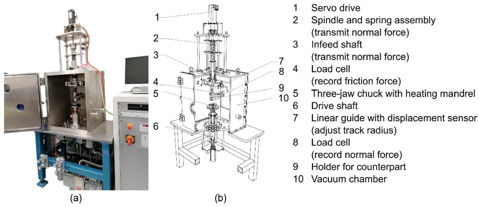
2.4.2. Microscale Tests

Microscale wear experiments, aimed at investigating the microscopic tribomechanical behavior, were carried out in a nanoindenter (KLA, G200, Milpitas, CA, USA) equipped with a blunt Berkovich diamond tip (3.1 µm tip radius) and operated in ambient air. Unlike usual nanoindentation, the application of a normal load was combined with a lateral motion of the sample stage in order to create a straight wear track. One wear cycle consisted of a lateral motion of the stage by 35 µm and returning to the origin of the wear track. This took place under a constant normal load of 1 mN, corresponding to a theoretical Hertzian pressure of 9.26 GPa at the contact center. For each wear test, 10,000 wear cycles were performed, which corresponds to a total length of 700 mm. After every 1000th cycle, the surface profile of the test location was recorded by profiling at a small load of 20 µN. The effective indentation depth into the coating was then calculated from the surface profile, and the wear volume was determined by post-test surface profiling using LSM (Keyence, VK-X-160K, Osaka, Japan). By combining the surface scans with the post-test wear volume, the respective wear volume after every 1000th cycle and the wear coefficient were determined, similarly to the macroscopic tests.

3. Results

3.1. Structure of MoS2 Coatings

The SEM investigations revealed the structure of the as-deposited coatings. The plane view of the surface as well as the FIB cross-sections of the respective coatings are shown in Figure 3. They provide insights into the influence of the deposition parameters.
From its surface structure and cross-section morphology, NoRot appeared to be homogenous and dense. In the cross-section (Figure 3b), no pores were visible over the entire layer thickness. In contrast, the coatings deposited with 3-fold substrate rotation showed some degree of porosity. Starting with RefRot (Figure 3c,d), a dendritic growth was visible at the coating surface. The cross-section showed some pores, especially in the lower section of the coating. This apparent accumulation near the substrate, and the fact that the pores appear larger at a higher depth, was likely an artifact from FIB milling. This artifact, which is similar to FIB curtaining, prevents measurement of the actual size of the pores and obscures the fact that they are likely distributed throughout the thickness of the coating. Nonetheless, HotRot, which was deposited at a higher chamber temperature, exhibited the highest apparent porosity (see Figure 3e,f). In addition, the dendritic growth on the surface was more pronounced. The slower rotational speed of the charging rack during the coating deposition process resulted in a denser structure in the cross-section images (Figure 3h).
EDX measurements at the top surface provided information about the chemical composition and stoichiometry of the coatings. FIB milling was used to create local cross-sections and measure the coating thickness. The results of both measurements are given in Table 2.
The coatings deposited with 3-fold rotation show nearly the same non-stoichiometric ratio of Mo:S1.6–1.7—i.e., the coatings have a sulfur-deficient characteristic. The Mo:S ratio of NoRot appears to be even further from 2.
RefRot exhibited a reference thickness of 2.3 µm. Increasing the chamber temperature to 150 °C promoted faster layer growth, as evidenced by the larger thickness of 3.0 µm for HotRot after the same deposition time. Reducing the rotational speed of the charging rack led to a slower layer growth, resulting in a thickness of 1.6 µm for LowRot. For NoRot, the parameters were different and the deposition time was simply adjusted to produce the same thickness as the reference.

3.2. Mechanical Properties

The results of the nanoindentation experiments are summarized in Figure 4 and Table 3. The indentation hardness and indentation modulus before and after short tribological tests (to 6300 cycles) are compared in Figure 4a,b.
NoRot exhibited, by far, the highest indentation hardness and modulus values. Furthermore, these values remained stable during wear testing. Within the 3-fold rotated specimens, HotRot exhibited lower and LowRot exhibited higher values than the reference RefRot. This means that increasing either the deposition temperature or substrate rotational speed resulted in a more compliant coating. The modulus of all three coatings was strongly increased after 6300 wear cycles, but the trend between the individual samples remained unchanged.

3.3. Tribological Behavior

3.3.1. Frictional Behavior and Endurance Performance

Representative COF curves over time (sliding cycles) for the four coatings, resulting from the long tests, are depicted in Figure 5.
While no obvious running-in behavior was observed for NoRot (Figure 5a), the three other coatings—RefRot, HotRot and LowRot (Figure 5b–d)—showed distinct running-in behavior (phase I). After the running-in was completed, a stationary and low COF was achieved for the three coatings deposited with substrate rotation (phase II). This occurred after different durations for each coating (see Table 4). In the further run, a stage could be observed in which the COF rises rapidly and remains at an elevated value for a longer period of time (Table 4), whereby this value approximately corresponded to that of the NoRot coating (Figure 5c,d). The behavior of the RefRot coating differed somewhat from this as the increase in COF was less pronounced, but considerable peaks could be detected (Figure 5b). Averaged values for the COF of the three mentioned phases for RefRot, HotRot and LowRot are given in Figure 6, and the duration of the different phases is summarized in Table 4.
The COF of NoRot was, from the beginning, at a higher level on average but remained in the range of 0.03 to 0.04, with a slightly increasing tendency during the complete test (Figure 5a). The peaks that occurred in a short period at about 150,000 cycles are to be considered as artifacts.
RefRot, HotRot and LowRot reached the termination criterion (COF > 0.3) within 98,080–168,820 cycles. LowRot exhibited the highest and HotRot exhibited the poorest lifetime; see Table 4. The test for the NoRot coating was stopped without observing coating failure until 260,000 cycles.

3.3.2. Wear Behavior

Wear was quantified after the short tests; cf. Section 2.4. The calculated wear coefficients for the disks are summarized in Figure 7.
For a better understanding of the processes during the running-in phase, additional tests were carried out both on the macroscale and on the microscale. On the macroscale, three interrupted tests were performed per coating, with 1000, 2500 and 6300 cycles. The other parameters for these tests were the same as in the short tests; see Section 2.4.1. For each test, the wear track was measured ex situ after the test and the wear coefficient was calculated. The microscale experiments were performed as described in Section 2.4.2. It should be explicitly noted that in the microscale case, profiling of the wear tracks was performed in situ, and the tests could, therefore, be carried out without interruption. The results of these tests are summarized in Figure 8a for the macroscale tests and Figure 8b for the microscale tests.
For the three coatings deposited with substrate rotation, the wear coefficient decreased strongly during the first few 1000 cycles and then reached a steady-state value (which has not yet been fully achieved in the macroscopic tests shown in Figure 8a). In contrast, NoRot showed a much lower and nearly constant wear coefficient. The curves qualitatively showed a good match between macroscale and microscale. The different absolute values (note the different scales in Figure 8) are explained by two main factors: (1) Due to the apparatus, the tests on the microscale could not be carried out under vacuum conditions; (2) the contact stress in the microscale tests was considerably higher than that in the macroscale tests (9.26 GPa instead of 1.17 GPa Hertzian pressure) due to the different indenter geometries. A SEM micrograph of the wear track of RefRot after tribological testing (6300 cycles) is depicted in Figure 9a. The surface inside the track looked much smoother than that of the as-deposited coating. The scratches at the edges were caused by handling. A cross-section of the marked zone is shown in Figure 9b, which shows the residual MoS2 coating. It is noteworthy that after the tribological loading, no more pores were visible, unlike in Figure 3d for the as-deposited coating. It can also be seen that the coating thickness was reduced, which cannot be solely attributed to material removal due to the short exposure time.

4. Discussion

The results show a strong influence of the deposition strategy on the coatings’ morphology, mechanical properties and tribological behavior.

4.1. Structure of MoS2 Coatings

MoS2, like all transition metal dichalcogenides, has a high tendency to form lattice defects. The stoichiometric ratio of S:Mo of 2 for the ideal MoS2 crystal is, therefore, mostly not attained. Furthermore, sulfur (32 u) has a much lower atomic weight than molybdenum (96 u). Due to the associated lower sublimation energy, sulfur has a higher tendency to desorb from the deposited surface. Therefore, sputter coatings tend to be sulfur deficient [28]. The MoS2 coatings produced in this work, with a stoichiometric ratio of S:Mo of about 1.6 (moderate sulfur deficiency for the coatings with substrate rotation) or 1.1 (strong sulfur deficiency for NoRot), can, thus, be considered representative of common PVD coatings.
The relatively homogeneous coatings, which can be fabricated by magnetron sputtering on samples without substrate rotation (represented by NoRot; see Figure 3b) and as presented in various publications [18,29], could not be reproduced in our work when 3-fold substrate rotation was applied, as it is required for the deposition of technical components. All coatings deposited with substrate rotation (RefRot, HotRot and LowRot; see Figure 3d,f,h) exhibited varying degrees of porosity. This porosity is due to the growth of the coatings. As already described in [29], MoS2 lamellae tend to grow normal to the interface. This growth mode dominates after only a few nm, even if crystal growth parallel to the surface is present at the beginning of deposition. Lattice defects due to the sub-stoichiometry of the layers act as nucleation sites and initialize vertical growth. As soon as such vertical lamellae are present, new deposits prefer to bind to their topmost reactive edge and not to the chemically rather inert top of the lower-lying parallel layers. Thus, once initiated, vertical growth is fast, whereas horizontal growth is more and more blocked by the presence of vertical lamellae, which makes the change from parallel to normal growth irreversible. Finally, high vertical lamellae lead to shadowing effects by stopping new deposits from reaching lower parts of the substrate, which ultimately results in the formation of pores [29,30]. This type of growth is particularly apparent in Figure 3c–f. The growth of the coatings can be influenced within some limits by the choice of the deposition parameters. The main growth of MoS2 lamellae normal to the interface, which results in porous coatings, can, apparently, not be avoided in deposition processes with 3-fold substrate rotation and/or with a relatively large target–substrate distance, which is generally given by the geometry of the deposition unit. The degree of porosity, in turn, is the most decisive factor for the resulting mechanical properties and the tribological behavior of the as-deposited coatings.
A small target–substrate distance ensures more homogeneous coatings, as shown by [21]. We can confirm this (Figure 3a,b). It is likely that fewer defects are incorporated in the first atomic layers, and therefore, a more uniform growth is possible. Furthermore, the atoms hit the substrate surface with higher energy (shorter path at a constant free path length) and with higher probability at favorable angles. Molecular dynamics simulations in [31] show the influence of the energy of the particle flow on the formed coating structure, with higher energies leading to denser coatings. Increased temperature near the target and re-sputtering effects may also play a role. However, in practice, the target–substrate distance is predetermined by the equipment and charging rack in the deposition unit and cannot be reduced at will. Increasing the chamber temperature, as represented by HotRot, did not show the expected effect. Instead of a more homogeneous coating, a coating with strongly pronounced dendritic growth and a high degree of pores was produced (Figure 3e,f). Well-known structural zone models, for example, according to [14] or [32], assume that the most advantageous coating structures form in the so-called transition zone. For the MoS2 coatings in this work, this zone would be, at a homologous temperature, around 0.2, which is approximately achieved with a chamber temperature of 150 °C. Thus, for MoS2, the model assumptions of the structural zone models cannot be fully confirmed, since, apparently, the effects described in the previous paragraph dominate. A lower rotational speed of the charging rack, on the other hand, leads to denser coatings, represented by LowRot (Figure 3g,h).
The degree of porosity can be estimated via various indicators—for example, by comparing the relative thicknesses of the as-deposited coatings with the deposition time kept constant. Looking at Table 2, it can, thus, be assumed that HotRot has about 90% more pores and RefRot has about 40% more pores than LowRot does.

4.2. Mechanical Properties

The measured indentation hardness and indentation modulus for NoRot are well in line with previously published results for sputtered coatings [33,34,35]. Combining this fact with the SEM observations, a dense structure for NoRot is evidenced. The coatings deposited with 3-fold substrate rotation all show lower indentation hardness and indentation modulus values compared to the values expected for dense coatings. Since SEM investigation revealed porous structures for these coatings, the drop in mechanical properties can be attributed to the porosity. Note that a higher (HotRot) and lower (LowRot) degree of porosity compared to RefRot results in more compliant and stiffer coatings, respectively. After tribological short tests, no significant change in the mechanical properties was found for NoRot. The indentation hardness and indentation modulus values were still on a comparable level considering the measurement error. The porous coatings showed a strong increase in hardness and modulus after the tribological test, hinting at a densification process. This is further supported by the cross-section shown in Figure 9, where the initial porosity is not apparent any longer after tribological testing. Assuming that the as-deposited NoRot coating is fully dense, RefRot, HotRot and LowRot still exhibit a deficit after compaction, with their stiffness accounting for only 32%, 31% and 42% of that of the reference. However, it cannot be excluded that this difference partly arises from a change in crystal orientation [36]. Indeed, crystal anisotropy is known to cause large differences in measured moduli [34].

4.3. Tribological Behavior

4.3.1. Frictional Behavior and Endurance Performance

The COF values achieved with RefRot, HotRot and LowRot, especially in phase II (compare Section 3.3.1, Figure 5b–d), are to be regarded as low compared with the values given in the literature for similar conditions, e.g., [37,38]. From [37,39], a COF of 0.02 can be inferred, which is very similar to those of our coatings. It is known from [12] that MoS2 films with a stoichiometric ratio of 1.5 provide minimum friction coefficients in a dry nitrogen atmosphere. Assuming that the tribological behavior is comparable in a nitrogen atmosphere and in vacuum, the stoichiometric ratio of 1.6 of our coatings RefRot, HotRot and LowRot should be close to the optimum with respect to the frictional behavior. Severe sulfur deficiency (NoRot) could be responsible for increasing the COF.
The pronounced running-in behavior of RefRot, HotRot and LowRot (see Figure 5b–d) can be explained as follows: In the as-deposited state, the coatings exhibited different degrees of porosity (see Figure 3d,f,h). After completing the running-in process, this porosity was largely eliminated below the wear track (see Figure 9b). At the same time, the coating became thinner. Thus, a compaction of the coating obviously occurred due to the acting pressure in combination with shear stresses. Thus, two simultaneous effects can be distinguished in the running-in phase: (a) the “classic” running-in wear, i.e., material removal in the near-surface area, and (b) the compaction of the coating. Both effects require energy input, which results in increased friction. Therefore, no running-in behavior could be observed for NoRot, which was already compact to a large extent in the as-deposited state. In the comparatively low-porosity LowRot coating, the compaction was relatively quickly completed, which is reflected by a short running-in period and a sharp decrease in the COF curve. In the more porous RefRot coating, this process took almost twice as long with a lower gradient in the COF curve. The compaction took the longest time for the very porous HotRot coating. The data strongly suggest that “classical” running-in wear does not play a prominent role in any of the coatings, but that the effect of compaction dominates. It is very interesting to note that the COF values of all three coatings deposited with substrate rotation are very similar after the running-in in the steady-state (phase II). This leads to the conclusion that, with respect to steady-state low friction, porosity (and, thus, deposition conditions) appears to be less significant than might initially have been expected. With regard to the practical application of MoS2 PVD coatings, it is, thus, possible to think of post-compaction following deposition as well as controlled running-in processes at high pressure, which may be the subject of future work.
Another possible effect is the reorientation of the MoS2 lamellae as described in [36], which occurs in parallel to the two aforementioned effects during the running-in phase but also afterwards. An explanation for the increase in friction in phase III for the coatings produced with substrate rotation could be a different structure in the direction of the substrate surface, whose properties are influenced by the substrate and which becomes tribologically effective when the coating has been partially removed due to erosion and wear debris. It is possible that this is related to an impeded reorientation of the MoS2 lamellae. Another explanation is that due to the changes in coating structure, the transfer of MoS2 to the counterbody (steel ball) worsened. However, each hypothesis requires further investigation.
As mentioned, NoRot exhibited a largely constant COF over the entire running time, which was, however, higher than the COF of the coatings with substrate rotation in phase II. It is noteworthy that the COF values for the coatings with substrate rotation, especially LowRot and RefRot, in phase III are around the level of NoRot. Nevertheless, this may be a coincidence and also requires further investigation.
The running time of all of the coatings (endurance performance) presented in this paper is within the range of results published in the literature [37,38,39,40]. The coatings can, therefore, be considered representative in this respect as well.

4.3.2. Wear Behavior

NoRot showed, by far, the lowest wear coefficient (Figure 7 and Figure 8) and, at the same time, the highest hardness and HIT/EIT ratio (Table 3). Furthermore, it has a severe sulfur deficiency. It is known from other studies [41] that distinct sulfur deficiency leads to higher wear resistance. The positive correlation between the HIT/EIT ratio and wear resistance of coatings is well known from the literature [23]. The meaning of the HIT/EIT ratio can be interpreted as follows: The wear is related to the yield strain (Re/E). The yield strain describes the ability of the coating to stretch under tribological stress before plastic deformation occurs. Since the yield strength Re scales with the hardness HIT, the HIT/EIT ratio is also a measurement of the yield strain. Coatings with a high HIT/EIT ratio, therefore, tolerate high surface deformation without failing in the sense of yielding and cracking [42].
However, the “conventional” calculation of the wear coefficient for the MoS2 coatings investigated here must be critically questioned. As mentioned in Section 2.4.1, the wear coefficient was calculated on the basis of the volume loss in the wear track. As described in Section 4.3.1, the porous coatings were initially dominated by compaction, which also led to a volume loss. This resulted in misleadingly high wear coefficients for the coatings deposited with 3-fold substrate rotation (Figure 7). This is reflected by the rapidly decreasing wear coefficients (see Figure 8). Figure 10 summarizes these processes.
Furthermore, the compaction of the coatings must still be considered when comparing the endurance performance of MoS2 coatings, because coatings of different thicknesses (and, thus, different lubricant volumes) are being compared.

5. Conclusions

Industrial deposition processes by magnetron sputtering require 3-fold substrate rotation. In the present work, the porosity of the MoS2 coatings could not be avoided completely due to the 3-fold substrate rotation and the associated target–substrate distance defined by the deposition unit and the charging rack. However, the degree of porosity can be influenced by varying the deposition parameters. Slower rotational speed of the charging rack allowed an increase in mechanical properties by reducing the degree of porosity, which, in turn, improved the tribological behavior. Increasing the chamber temperature had the opposite effect. Consequently, the resulting degree of porosity constitutes a limiting factor for a long lifetime. Moreover, we have shown, using tribological tests, that the porous coatings are compacted first, and then, the compacted coating is removed in wear processes, which, all in all, leads to a good tribological behavior with a low COF after compaction.
A consequence of the compaction of the porous coatings is that both the wear coefficient after short test durations and the measured coating thicknesses of the as-deposited coatings cannot be used to compare the MoS2 coatings. Reliable comparisons of the coatings can only be made after compaction is completed. It should be particularly emphasized that wear coefficients must be carefully evaluated for MoS2 coatings when their porosity is unknown. Therefore, we suggest that porosity should always be evaluated for MoS2 coatings, for example, by making FIB cross-sections and performing indentation tests. Alternatively, the running-in behavior can be investigated in short tests on a tribometer, from which the porosity of the coatings can also be estimated.
Highly porous coatings should be compacted after deposition using an appropriate process or should be treated using a suitable running-in process. Another possibility to fabricate denser PVD coatings is to use more cathodes, for example, four to six, if the deposition unit allows. In addition, applying a substrate bias voltage should guide the ion flux to the substrates and lead to denser coating morphology. However, it should be noted that previous work [18] showed that applying a bias voltage resulted in poorer tribological behavior of the coatings. Reducing the target–substrate distance or the pressure (the product of the two variables is relevant) are further theoretical possibilities, but these are generally also limited by the equipment. New technologies such as high-power impulse magnetron sputtering (HiPIMS) can also be applied to create denser coatings.
In our investigations, we observed that porous MoS2 coatings need not be too disadvantageous in tribological terms when compacted. With regard to low COFs, they even seem to be advantageous. Lower running times in tribometer tests may possibly be due to different coating thicknesses (and, thus, different lubricant volumes).
Therefore, to compare the lifetimes of MoS2-coated components, as often found in the literature, only coatings with a comparable morphology (compacted coatings) and thickness should be used. We strongly encourage further investigation of the effects of compaction on the tribological behavior of MoS2 coatings in the future.

Author Contributions

Conceptualization, A.S., S.K., E.B., B.M. (Benoit Merle), and S.T.; investigation, A.S. and S.K.; resources, B.M. (Benoit Merle) and S.T.; writing—original draft preparation, A.S., S.K., and S.T.; writing—review and editing, E.B., B.M. (Bernd Meyer), B.M. (Benoit Merle), and S.T.; visualization, A.S. and S.K.; supervision, E.B., B.M (Bernd Meyer), B.M. (Benoit Merle), and S.T.; funding acquisition B.M. (Bernd Meyer), B.M. (Benoit Merle), and S.T. All authors have read and agreed to the published version of the manuscript.

Funding

This research was funded by the German Research Foundation (DFG) Priority Program SPP 2074 “Fluid-free lubrication systems with high mechanical loads”, grant numbers ME 4368/7-1, ME 2670/8-1 and TR 1043/7-1. S.K. and E.B. acknowledge partial funding from the European Research Council (ERC) under the European Union’s Horizon 2020 research and innovation program (microKIc-Microscopic Origins of Fracture Toughness, grant agreement no. 725483). This publication was additionally funded by the German Research Foundation (DFG) and the University of Bayreuth in the funding program Open Access Publishing.

Institutional Review Board Statement

Not applicable.

Informed Consent Statement

Not applicable.

Data Availability Statement

All data needed to evaluate the conclusions are present in the paper. Additional data may be requested from the authors.

Acknowledgments

The authors greatly acknowledge the continuous support of Friedrich-Alexander-Universität Erlangen-Nürnberg (FAU) and Universität Bayreuth. A. Seynstahl and S. Tremmel thank S. Wartzack from Engineering Design (FAU) for the opportunity to use resources. This research used resources from the Center for Nanoanalysis and Electron Microscopy (CENEM) at Friedrich-Alexander-Universität Erlangen-Nürnberg (FAU).

Conflicts of Interest

The authors declare no conflict of interest.

References

  1. Sun, X. Solid Lubricants for Space Mechanisms. In Encyclopedia of Tribology; Wang, Q.J., Chung, Y.-W., Eds.; Springer: Boston, MA, USA, 2013; pp. 3165–3172. ISBN 978-0-387-92896-8. [Google Scholar]
  2. Vazirisereshk, M.R.; Martini, A.; Strubbe, D.A.; Baykara, M.Z. Solid Lubrication with MoS2: A Review. Lubricants 2019, 7, 57. [Google Scholar] [CrossRef] [Green Version]
  3. Scharf, T.W.; Prasad, S.V. Solid Lubricants: A Review. J. Mater. Sci. 2013, 48, 511–531. [Google Scholar] [CrossRef]
  4. Chen, Z.; He, X.; Xiao, C.; Kim, S. Effect of Humidity on Friction and Wear—A Critical Review. Lubricants 2018, 6, 74. [Google Scholar] [CrossRef] [Green Version]
  5. Martin, J.M.; Donnet, C.; Le Mogne, T.; Epicier, T. Superlubricity of Molybdenum Disulphide. Phys. Rev. B 1993, 48, 10583–10586. [Google Scholar] [CrossRef] [PubMed]
  6. Martin, J.M.; Pascal, H.; Donnet, C.; Le Mogne, T.; Loubet, J.L.; Epicier, T. Superlubricity of MoS2: Crystal Orientation Mechanisms. Surf. Coat. Technol. 1994, 68–69, 427–432. [Google Scholar] [CrossRef]
  7. Donnet, C.; Martin, J.M.; Le Mogne, T.; Belin, M. Super-Low Friction of MoS2 Coatings in Various Environments. Tribol. Int. 1996, 29, 123–128. [Google Scholar] [CrossRef]
  8. Hilton, M.R.; Fleischauer, P.D. TEM Lattice Imaging of the Nanostructure of Early-Growth Sputter-Deposited MoS2 Solid Lubricant Films. J. Mater. Res. 1990, 5, 406–421. [Google Scholar] [CrossRef]
  9. Fleischauer, P.D. Effects of Crystallite Orientation on Environmental Stability and Lubrication Properties of Sputtered MoS2 Thin Films. A S L E Trans. 1984, 27, 82–88. [Google Scholar] [CrossRef]
  10. Spalvins, T. Lubrication with Sputtered MoS2 Films: Principles, operation, and Limitations. J. Mater. Eng. Perform. 1992, 1, 347–351. [Google Scholar] [CrossRef]
  11. Kokalj, D.; Debus, J.; Stangier, D.; Moldenhauer, H.; Nikolov, A.; Wittig, A.; Brümmer, A.; Tillmann, W. Controlling the Structural, Mechanical and Frictional Properties of MoSx Coatings by High-Power Impulse Magnetron Sputtering. Coatings 2020, 10, 755. [Google Scholar] [CrossRef]
  12. Dimigen, H.; Hübsch, H.; Willich, P.; Reichelt, K. Stoichiometry and Friction Properties of Sputtered MoSx Layers. Thin Solid Films 1985, 129, 79–91. [Google Scholar] [CrossRef]
  13. Zhang, X.; Vitchev, R.; Lauwerens, W.; Stals, L.; He, J.; Celis, J.-P. Effect of Crystallographic Orientation on Fretting Wear Behaviour of MoSx Coatings in Dry and Humid Air. Thin Solid Films 2001, 396, 69–77. [Google Scholar] [CrossRef]
  14. Thornton, J.A. Influence of Apparatus Geometry and Deposition Conditions on the Structure and Topography of Thick Sputtered Coatings. J. Vac. Sci. Technol. 1974, 11, 666–670. [Google Scholar] [CrossRef]
  15. Messier, R.; Giri, A.P.; Roy, R.A. Revised Structure Zone Model for Thin Film Physical Structure. J. Vac. Sci. Technol. Vac. Surf. Films 1984, 2, 500–503. [Google Scholar] [CrossRef]
  16. Weise, G.; Teresiak, A.; Bächer, I.; Markschläger, P.; Kampschulte, G. Influence of Magnetron Sputtering Process Parameters on Wear Properties of Steel/Cr3Si or Cr/MoSx. Surf. Coat. Technol. 1995, 76–77, 382–392. [Google Scholar] [CrossRef]
  17. Weise, G.; Mattern, N.; Hermann, H.; Teresiak, A.; Bächer, I.; Brückner, W.; Bauer, H.-D.; Vinzelberg, H.; Reiss, G.; Kreissig, U.; et al. Preparation, Structure and Properties of MoSx Films. Thin Solid Films 1997, 298, 98–106. [Google Scholar] [CrossRef]
  18. Vierneusel, B.; Tremmel, S.; Wartzack, S. Effects of Deposition Parameters on Hardness and Lubrication Properties of Thin MoS2 Films. Mater. Werkst. 2012, 43, 1029–1035. [Google Scholar] [CrossRef]
  19. Vierneusel, B.; Tremmel, S.; Wartzack, S. Monte Carlo Simulation of the MoS2 Sputtering Process and the Influence of the Normalized Momentum on Residual Stresses. J. Vac. Sci. Technol. Vac. Surf. Films 2015, 33, 061501. [Google Scholar] [CrossRef]
  20. Vierneusel, B.; Schneider, T.; Tremmel, S.; Wartzack, S.; Gradt, T. Humidity Resistant MoS2 Coatings Deposited by Unbalanced Magnetron Sputtering. Surf. Coat. Technol. 2013, 235, 97–107. [Google Scholar] [CrossRef]
  21. Vierneusel, B.; Benker, L.; Tremmel, S.; Göken, M.; Merle, B. Isolating the Effect of Residual Stresses on Coating Wear by a Mechanical Stress Relaxation Technique. Thin Solid Films 2017, 638, 159–166. [Google Scholar] [CrossRef]
  22. Fleischauer, P.D. Fundamental Aspects of the Electronic Structure, Materials Properties and Lubrication Performance of Sputtered MoS2 Films. Thin Solid Films 1987, 154, 309–322. [Google Scholar] [CrossRef]
  23. Holmberg, K.; Ronkainen, H.; Laukkanen, A.; Wallin, K.; Hogmark, S.; Jacobson, S.; Wiklund, U.; Souza, R.M.; Ståhle, P. Residual Stresses in TiN, DLC and MoS2 Coated Surfaces with Regard to Their Tribological Fracture Behaviour. Wear 2009, 267, 2142–2156. [Google Scholar] [CrossRef]
  24. Bückle, H. Mikrohärteprüfung und ihre Anwendung; Berliner Union: Stuttgart, Germany, 1965. [Google Scholar]
  25. Merle, B.; Higgins, W.H.; Pharr, G.M. Critical Issues in Conducting Constant Strain Rate Nanoindentation Tests at Higher Strain Rates. J. Mater. Res. 2019, 34, 3495–3503. [Google Scholar] [CrossRef] [Green Version]
  26. Oliver, W.C.; Pharr, G.M. An Improved Technique for Determining Hardness and Elastic Modulus Using Load and Displacement Sensing Indentation Experiments. J. Mater. Res. 1992, 7, 1564–1583. [Google Scholar] [CrossRef]
  27. Archard, J.F. Contact and Rubbing of Flat Surfaces. J. Appl. Phys. 1953, 24, 981–988. [Google Scholar] [CrossRef]
  28. Buck, V. Lattice Parameters of Sputtered MoS2 Films. Thin Solid Films 1991, 198, 157–167. [Google Scholar] [CrossRef]
  29. Moser, J.; Liao, H.; Levy, F. Texture Characterisation of Sputtered MoS2 Thin Films by Cross-Sectional TEM Analysis. J. Phys. Appl. Phys. 1990, 23, 624–626. [Google Scholar] [CrossRef]
  30. Bertrand, P.A. Orientation of Rf-Sputter-Deposited MoS2 Films. J. Mater. Res. 1989, 4, 180–184. [Google Scholar] [CrossRef]
  31. Müller, K. Dependence of Thin-film Microstructure on Deposition Rate by Means of a Computer Simulation. J. Appl. Phys. 1985, 58, 2573–2576. [Google Scholar] [CrossRef]
  32. Adamik, M.; Tomov, I.; Kaiser, U.; Laux, S.; Schmidt, C.; Richter, W.; Safran, G.; Barna, P.B. Structure Evolution of Stratified NdF3 Optical Thin Films; Hall, R.L., Ed.; SPIE: San Diego, CA, USA, 1997; p. 123. [Google Scholar]
  33. Renevier, N.; Fox, V.; Teer, D.; Hampshire, J. Coating Characteristics and Tribological Properties of Sputter-Deposited MoS2/Metal Composite Coatings Deposited by Closed Field Unbalanced Magnetron Sputter Ion Plating. Surf. Coat. Technol. 2000, 127, 24–37. [Google Scholar] [CrossRef]
  34. Colas, G.; Serles, P.; Saulot, A.; Filleter, T. Strength Measurement and Rupture Mechanisms of a Micron Thick Nanocrystalline MoS2 Coating Using AFM Based Micro-Bending Tests. J. Mech. Phys. Solids 2019, 128, 151–161. [Google Scholar] [CrossRef] [Green Version]
  35. Kao, W.H. Tribological Properties and High Speed Drilling Application of MoS2–Cr Coatings. Wear 2005, 258, 812–825. [Google Scholar] [CrossRef]
  36. Moser, J.; Lévy, F. Crystal Reorientation and Wear Mechanisms in MoS2 Lubricating Thin Films Investigated by TEM. J. Mater. Res. 1993, 8, 206–213. [Google Scholar] [CrossRef] [Green Version]
  37. Roberts, E. Ultralow Friction Films of MoS2 for Space Applications. Thin Solid Films 1989, 181, 461–473. [Google Scholar] [CrossRef]
  38. Theiler, G.; Gradt, T.; Österle, W.; Brückner, A.; Weihnacht, V. Friction and Endurance of MoS2/Ta-C Coatings Produced by Laser Arc Deposition. Wear 2013, 297, 791–801. [Google Scholar] [CrossRef]
  39. Roberts, E.W.; Williams, B.J.; Ogilvy, J.A. The Effect of Substrate Surface Roughness on the Friction and Wear of Sputtered MoS2 Films. J. Phys. Appl. Phys. 1992, 25, A65–A70. [Google Scholar] [CrossRef]
  40. Fleischauer, P.D.; Hilton, M.R.; Bauer, R. Paper V (i) Effects of microstructure and adhesion on performance of sputter-deposited MoS2 solid lubricant coatings. In Tribology Series; Elsevier: Amsterdam, The Netherlands, 1990; Volume 17, pp. 121–128. ISBN 978-0-444-88676-7. [Google Scholar]
  41. Wang, J.; Lauwerens, W.; Wieers, E.; Stals, L.M.; He, J.; Celis, J.P. Structure and Tribological Properties of MoSx Coatings Prepared by Bipolar DC Magnetron Sputtering. Surf. Coat. Technol. 2001, 139, 143–152. [Google Scholar] [CrossRef]
  42. Finkin, E.F. Examination of Abrasion Resistance Criteria for Some Ductile Metals. J. Lubr. Technol. 1974, 96, 210–214. [Google Scholar] [CrossRef]
Figure 1. Schematic view of the deposition unit H-O-T TT 300 K4, showing the 3-fold substrate rotation and the position of the cathodes.
Coatings 11 00455 g001
Figure 2. (a) Overview of the vacuum ball-on-disk tribometer. (b) Schematic of the vacuum ball-on-disk tribometer, illustrating the mechanisms of force application and measurement.
Coatings 11 00455 g002
Figure 3. (a,c,e,g) Plane view of the as-deposited coating surfaces. (b,d,f,h) Prepared focused ion beam (FIB) cross-sections of the as-deposited coatings. The sequence of layers from top to bottom is deposited Pt, MoS2 coating and steel substrate. (a,b) NoRot, (c,d) RefRot, (e,f) HotRot and (g,h) LowRot coatings.
Coatings 11 00455 g003
Figure 4. Nanoindentation results. (a) Indentation hardness HIT before and after a ball-on-disk short test (6300 cycles). (b) Indentation modulus EIT before and after a ball-on-disk short test (6300 cycles). The latter was measured in the center of a wear track.
Coatings 11 00455 g004
Figure 5. The results of the ball-on-disk long tests are plotted by the coefficient of friction (COF) trend versus the number of cycles and are separated into three phases until coating failure. (a) NoRot, (b) RefRot, (c) HotRot and (d) LowRot coatings.
Coatings 11 00455 g005
Figure 6. Average values of COF (according to Figure 5) for the three phases identified in the long tests: Phase I—running-in; phase II—steady-state; phase III—elevated COF for the three coatings deposited with substrate rotation.
Coatings 11 00455 g006
Figure 7. Calculated wear coefficient after ball-on-disk short tests (6300 cycles).
Coatings 11 00455 g007
Figure 8. (a) Results of the ball-on-disk short test performed with 1000, 2500 and 6300 cycles. (b) Results of wear test on microscale performed up to 10,000 cycles. Please note the different scales in the wear coefficient.
Coatings 11 00455 g008
Figure 9. (a) Wear track of RefRot after macroscale ball-on-disk short test (6300 cycles); (b) FIB-milled cross-section of the worn wear track of RefRot.
Coatings 11 00455 g009
Figure 10. Schematic representation of the different coatings and their evolution in tribological contact. (a) For the identical deposition time, the coatings produced with sample rotation have, due to their porosity, a higher thickness d. (b) During running-in, the porous coating is compacted, contrary to the coating without rotation; the indentation depth is not a good indicator for the wear. (c) During steady-state wear, the initially porous coating is further compacted according to the increasing indentation depth caused by wear, while no such compaction takes place in the compact coating produced without sample rotation.
Coatings 11 00455 g010
Table 1. Deposition parameters of the four MoS2 coatings.
Deposition ParametersCoating Designation
NoRotRefRotHotRotLowRot
Rotation strategy-3-fold3-fold3-fold
Target–substrate distance in mm65250250250
Duration in s300420042004200
Sputtering power in kW1.32.02.12.1
Bias voltage in V0000
Argon gas flow in sccm115120120120
Argon pressure in Pa0.700.710.760.70
Chamber temperature in °C505015050
Rotational speed in rpm-661
Table 2. Results of the measurement of layer thickness and stoichiometry (energy-dispersive X-ray spectroscopy, EDX) by analyzing the cross-section SEM images of MoS2 coatings in as-deposited state.
ParameterNoRotRefRotHotRotLowRot
Mo/S-ratio1.141.671.651.61
Coating thickness in µm2.32.33.01.6
Table 3. Indentation hardness HIT, indentation modulus EIT and HIT/EIT ratio measured by nanoindentation (n = 9) for the as-deposited coatings and for the wear track after 6300 cycles (ball-on-disk short test). The error for the HIT/EIT ratios was calculated via Gaussian error propagation.
ParameterNoRotRefRotHotRotLowRot
As-Deposited Coating
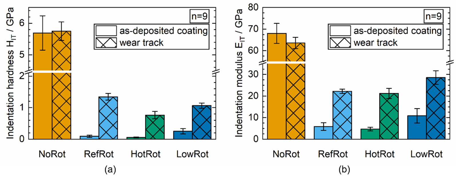
HIT in GPa5.69 ± 0.540.09 ± 0.030.06 ± 0.010.25 ± 0.09
EIT in GPa68.0 ± 4.75.86 ± 1.74.7 ± 0.910.8 ± 3.3
HIT/EIT ratio0.084 ± 0.0100.016 ± 0.0070.012 ± 0.0040.023 ± 0.011
Wear Track
HIT in GPa5.75 ± 0.291.34 ± 0.110.76 ± 0.121.06 ± 0.08
EIT in GPa63.6 ± 2.622.2 ± 1.021.2 ± 2.428.6 ± 3.1
Table 4. Number of cycles of each of phases I, II and III during the ball-on-disk long tests (according to Figure 5), except NoRot (no identifiable phases).
Coating DesignationCycles in 103
Phase IPhase IIPhase III
RefRot14.365.774.0
HotRot21.033.042.5
LowRot5.070.392.0
Publisher’s Note: MDPI stays neutral with regard to jurisdictional claims in published maps and institutional affiliations.

