Abstract
Tungsten oxide WO3 thin films are deposited by DC reactive magnetron sputtering. The Reactive Gas Pulsing Process (RGPP) associated with the GLancing Angle Deposition method (GLAD) are implemented to produce zigzag columnar structures. The oxygen injection time (tON time) and the pulsing period are kept constant. Three tilt angles α are used: 75, 80, and 85° and the number of zigzags N is progressively changed from N = 0.5, 1, 2, 4, 8 to 16. For each film, refractive index, extinction coefficient, and absorption coefficient are calculated from optical transmission spectra of the films measured in the visible region from wavelength values only. Absorption and extinction coefficients monotonously drop as the number of zigzags increases. Refractive indices are the lowest for the most grazing tilt angle α = 85°. The highest refractive index is nevertheless obtained for a number of zigzags close to four. This optimized optical property is directly correlated to changes of the microstructure, especially a porous architecture, which is favored for high tilt angles, and tunable as a function of the number of zigzags.
1. Introduction
Structuring of solid materials at the micro- and nanoscale appeared as a key strategy to generate novel materials properties. Based-on two major approaches to achieve nanoscale engineering, the top-down and bottom-up approaches also generated technological and scientific challenges, especially in thin films science [1,2]. This structuring of thin films may become a complex task for ceramic materials produced by bottom-up methods since they may require reactive processes [3,4,5]. Accordingly, resulting film properties do not only depend on composition (many chemical and physical characteristics of metal oxide thin films are closely linked to their chemical composition, especially the oxygen-to-metal concentrations ratio), but the role of structure becomes a fundamental parameter particularly for optical materials [6,7]. It is well known that the films structure at the sub-micrometric scale can also influence their performances [8]. As a result, design and growth control of nanostructures turn into a fundamental issue in order to tune the optical properties by playing on architectural features of ceramic thin films [9].
Among ceramic compounds, transition metal oxides represent an exciting class of materials since they exhibit a wide range of physical and chemical behaviors [10,11]. Of interest, tungsten trioxide (WO3) thin films have been thoroughly studied due to their strong potential and concrete applications as active layers for gas sensors [12], optical coatings due to their high refractive index [13], transparent conducting oxides [14], and electrochromic devices [15]. However, whatever the end-user and the WO3 functionality, understanding some correlations between micro- and nanostructure of WO3 thin films and their physical properties still remains a scientific motivation. To this aim, structuring of thin films by means of bottom-up ways has been the focus of substantial efforts and promising routes emerged in the last half century [16,17]. To play with micro- and nanostructure of thin films, the GLancing Angle Deposition method (GLAD) is a recent and very attractive approach [18]. Typically, two degrees of freedom characterizes the GLAD experimental setup: the deposition angle α defined as the angle between the substrate normal and the direction of incident vapor flux (also called tilt angle), and the substrate rotation ϕ about its normal defining the azimuthal position of the substrate [19]. These two key parameters modify in an indirect way, the position of the particle source. The produced architectures can be of several types: (i) oriented columns; (ii) columnar zigzags by alternating periodically the deposition angle from +α to −α maintaining constant the azimuthal angle ϕ around the substrate or with a 180° rotation of ϕ keeping constant α angle; (iii) helices by means of a continuous rotation of ϕ keeping a constant tilt angle α [20]. In addition, adjusting precisely α and ϕ parameters and combining some recent improvements such as a phisweep motion [21] or a co-deposition process [22], more original structures can be obtained. Such developments exploit the effects of shadowing created by a tilted substrate relative to normal incidence, and also by a change of the direction of the particle flux through a rotating substrate during the film growth, which extend even more the panel of engineered nanostructures [23]. As a result, the GLAD process allows fabricating a wide range of architectures (tilted columns, spirals, zigzags, pillars, and so on …), controlling only two operating parameters, namely, the tilt angle α and the substrate rotation ϕ angle, providing several degrees of freedom to create original and innovative columnar patterns. In addition, it is important to note that thin films obtained by this GLAD technique systematically exhibited many extended behaviors (optics, acoustics, electronics, and so on) compared to coatings produced by conventional sputtering approaches [12,18,20].
Till now, the GLAD technique has ever been explored for metallic oxides, and sometimes for WO3 thin films [24]. Most investigations have been devoted to tilted columnar thin films showing that their refractive index drops as the incident angle of the particle flux rises due to an increasing porous structure [25,26,27]. In this paper, we report on WO3 thin films exhibiting a zigzag columnar architecture (WO3 material was chosen since it exhibits a high refractive index, which allows a significant tuneability of optical properties by playing on the film microstructure). The purpose is mainly focused on the effect of a zigzag architecture, especially the tilt angle α and the number of zigzags N, on the optical properties of WO3 thin films. For a constant film’s thickness and by increasing the number of zigzags N, a maximum refractive index can be reached whatever the tilt angle used to prepare WO3 films. This optimized index is discussed, considering the evolution of the films’ morphology and structure at the micro- and nanoscale.
2. Materials and Methods
2.1. Operating Conditions for WO3 Films Growth
WO3 thin films were prepared by the Reactive Gas Pulsing Process (RGPP) in a custom-made magnetron sputtering system consisting of a 40 L vacuum chamber as shown in Figure 1. It was evacuated with a turbomolecular pump, backed by a mechanical pump leading to an ultimate pressure lower than 10−5 Pa. A tungsten circular target (54 mm diameter and purity 99.9 at.%) was fixed at 65 mm from the center of the substrate holder. The target was DC sputtered using a constant current IW = 100 mA (the corresponding current density was JW = 50 A m−2). A pre-sputtering time was applied for 5 min in order to remove the contamination layer on the target surface and stabilize the process. The argon flow rate was kept constant at qAr = 1.2 sccm. A constant pumping speed S = 10 L s−1 was used leading to an argon partial pressure pAr = 2.8 × 10⁻³ mbar. Oxygen mass flow rate qO2 was pulsed during WO3 deposition by means of the Reactive Gas Pulsing Process (RGPP) [28]. A constant pulsing period P = 16 s was used. For all depositions, the oxygen injection time tON was 12.8 s, which corresponds to a duty cycle dc = 80% of the pulsing period P (dc = tON/P). This duty cycle was selected since such operating conditions correspond to the deposition of stoichiometric WO3 thin films [29]. The maximum oxygen flow rate was qO2Max = 2.4 sccm. This value corresponds to the oxygen amount required to completely avalanche the reactive sputtering process in the oxidized sputtering mode. During the tOFF time, the oxygen mass flow rate was completely stopped (qO2min = 0 sccm). The substrate holder was grounded, and no external heating was added. The angle of inclination of the substrate holder (tilt angle, namely, α), could be changed from 0 to 90° compared to the substrate normal. The rotating speed ϕ was computer-controlled and could be adjusted from 0 to a few revolutions per hour.
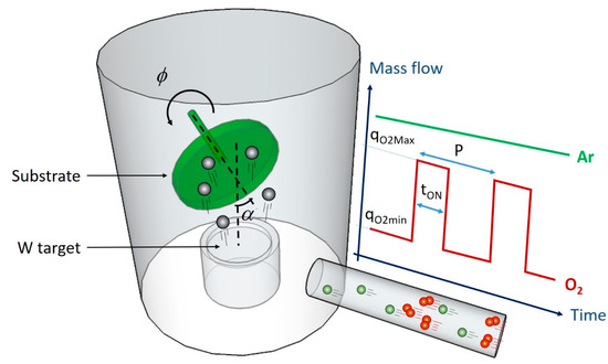
Figure 1.
Schematic illustration of the vacuum sputtering system used to deposit tungsten oxide thin films coupling GLancing Angle Deposition (GLAD) and Reactive Gas Pulsing Process (RGPP) techniques. The substrate can be tilted (angle α between the normal axes of the substrate and target), fixed or rotated (ϕ parameter) during the deposition stage. The tilt angle α can be adjusted from 0 to 90° and the substrate rotation ϕ can be 0 to a few revolutions per hour. Argon mass flow rate is kept constant, whereas oxygen mass flow rate is periodically controlled vs. time following a rectangular signal. Maximum and minimum oxygen flow rates (qO2Max and qO2min, respectively), pulsing period P and oxygen injection time tON are computer-controlled.
Substrates were standard microscope glass and (100) silicon wafer. Glass was used for optical transmission measurements, whereas silicon allows a frank fracture for microscopic cross-section observations. They were ultrasonically cleaned in acetone, ethanol, and deionized water for 10 min and dried in an oven at 60 °C for 20 min. The film’s thickness was measured by profilometry, and the deposition time was adjusted in order to prepare WO3 films with a thickness of 1 µm. For the deposition of a zigzag columnar structure, 3 tilt angles α were used: 75, 80, and 85°. For each tilt angle, the substrate was periodically turned with discrete 180° rotations. The number of zigzags N was gradually increased following N = 0.5, 1, 2, 4, 8, and 16 keeping a total film thickness of 1 µm. As a result, the number of 180° rotations directly gives the number of zigzags, which can be checked from cross-section SEM observations.
2.2. Characterization
Morphology of WO3 films was observed with a Dual Beam SEM/FIB FEI Helios 600i microscope on the fractured cross-section. Optical transmission spectra of the films deposited on glass substrates were recorded with a Lambda 900 UV–visible optical spectrometer. A mask (black piece) with a hole of 1 mm diameter was placed in the light path, to limit the observed area on the film. This mask allows probing a nearly constant thickness and avoid thickness gradient, which is especially substantial in GLAD films (intrinsic to the GLAD process). Placing such a mask, the thickness gradient was estimated to be less than 1% of the probed film thickness. Optical transmittance spectra of thin films deposited on glass substrate were recorded in the visible range. The scanning wavelength ranged from 300 nm to 850 nm, with 1 nm s−1 scanning speed. In order to get optical properties of WO3 films, the Swanepoel’s method was implemented. This method was used because it requires only two transmission spectra (one at normal incidence and another at oblique incidence) and optical properties can be determined from wavelength values only [30]. To this aim, optical transmission vs. wavelength was recorded at 0° (normal incidence), and at ±30° (oblique incidence) in order to check the homogeneity of the probed part of the sample.
3. Results and Discussion
3.1. Microstructure
Cross-sections of WO3 thin films were systematically observed by SEM. Figure 2 illustrates a typical series of zigzag columnar structures prepared with a duty cycle dc = 80% of the pulsing period P and with a tilt angle α = 80°. The number of zigzags N as well as the column tilt angle β (angle between the substrate normal and the column center axis) can be easily measured. For N = 0.5 (i.e., tilted columns), β changes from 50, 52, and 53° as α rises from 75, 80, and 85°, respectively. As usually reported with the GLAD process, this column angle β is always lower than α angle. These β vs. α values well correlate with Tait et al. equation (also known as the cosine rule) relating both angles together via a geometric analysis of the intercolumn shadowing geometry [31]. As the number of zigzags increases, it is worth of noting that the column tilt angle β is not uniform but gradually varies from sublayer to sublayer. As previously reported by Hawkeye et al. [32], the angle β is incremented up to a few degrees after each column arm deposition, then saturates after several arm numbers for any initial tilt angle.
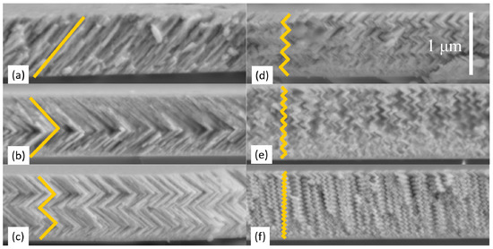
Figure 2.
Cross-section views of WO3 thin films 1 µm thick exhibiting a zigzag structure. Films were sputter-deposited on (100) Si wafer with a tilt angle α = 80° and a duty cycle dc = 80% of the pulsing period P. The number of zigzags N was systematically increased: (a) 1/2, (b) 1, (c) 2, (d) 4, (e) 8, and (f) 16. The scale is the same for all pictures.
This β evolution is due to the modified surface topography when depositing onto a pre-existing columnar arm. As a result, the effective tilt angle is not the real tilt angle α and varies over the film surface. The shadowing effect strongly depends on local variations of the surface geometry. From the second arm growth, particles impinge on the growing film and so, on the column apex according to an effective tilt angle significantly higher than angle α leading to an increase of β after a few deposited arms.
As the zigzag films thickness increases, widening of the column cross-section can also be observed as commonly noticed in tilted columnar GLAD films, and although the change of the growth direction induced by the 180° ϕ rotations. This structural broadening is well described by a power law connecting column width and film’s thickness via a scaling exponent describing how quickly the columns enlarge [33]. Despite the abrupt alternation of the tilt angle from +α to −α during the zigzag fabrication process, the column widening is intrinsic to the surface growth due to the ballistic regime of sputtered particles and the shadowing effect.
As the number of zigzags N increases, the zigzag architecture becomes less and less distinguishable, i.e., the column angle β and the zigzag design still remain observable for N = 16 (Figure 2f). However, a further increase of N definitely leads to an undefined zigzag shape, but wide and spaced columns perpendicular to the substrate surface instead. By increasing the number of zigzags, the length of a column arm reduces and becomes lower than a few tens nanometers. The deposition process behaves as a segmented growth. Intervals associated to the abrupt 180° ϕ rotations produce the growth of a new column. The latter develops on the opposite side at the apex of the previous column. The new column does not grow long enough for producing a significant shadowing effect leading to vertically oriented columns.
This segmented characteristic of the zigzag growth also produces some effects on the films’ density. Gu et al. [34] and Hass et al. [35] clearly reported that the porous structure changes as a function of the number of zigzags, and such a zigzag architecture exhibits three types of porosities with a distinct pores scale for each type. This hierarchical nature of the film’s porosity cannot be clearly distinguished from our SEM cross-section observations (Figure 2). However, these different types of porosities will be considered in § 3.3 to discuss some correlations between refractive index of WO3 zigzag films and their porous microstructure.
3.2. Optical Properties
Optical transmittance spectra of WO3 thin films deposited on glass substrate were measured in the visible range and for various numbers of zigzags (Figure 3). A standard WO3 films (tilt angle α = 0° and without oxygen pulsing, i.e., dc = 100% of the pulsing period P) was also recorded and taken as a reference. Typical interference fringes (as commonly observed for dielectric thin films) are obtained whatever the number of zigzags. The film prepared by conventional sputtering process (α = 0°) exhibits the highest amplitude of the interference fringes.
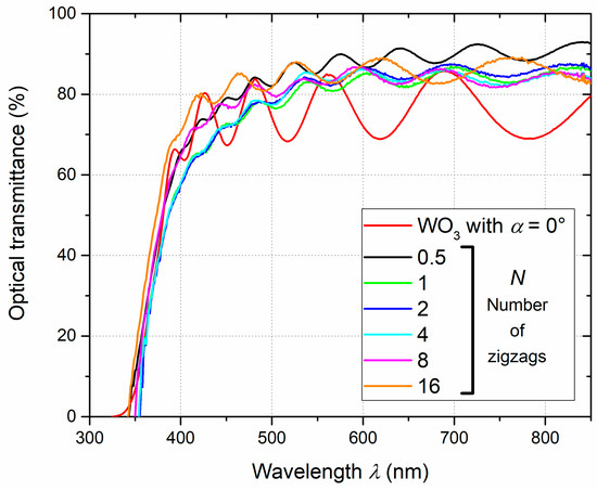
Figure 3.
Optical transmittance spectra in the visible range of 1 µm thick WO3 zigzag thin films prepared on glass substrate with various numbers of zigzags N = 0.5 to 16. Films were deposited with a tilt angle α = 80° and a duty cycle dc = 80% of the pulsing period P. A standard WO3 films is shown as a reference (α = 0° and without oxygen pulsing, i.e., dc = 100% of the pulsing period P).
Such amplitude is strongly reduced for zigzag films. This is directly connected to the dense structure produced for WO3 film with α = 0°, whereas a more porous architecture is obtained for tilted and zigzag films (cf. discussion later). In addition, fringes tend to disappear at wavelengths close to the absorption edge and the average transmittance of zigzag films smoothly increases as a function of the wavelength, especially from 400 nm where it is around 60–70%, and beyond 80–90% at 800 nm (average transmittance is below 80% in the visible range for WO3 film with α = 0°). This is mainly assigned to a more dispersive character of GLAD metal oxide thin films [36,37]. Changes of the growth direction (ϕ angle alternates from 0 to 180° for zigzags deposition) create interfaces, which disturb the wave propagation through the films and favor absorption phenomena. Surface roughness of GLAD films also increases significantly for grazing incident angles (i.e., higher than 70°), and contributes in the same manner to the light dispersion [38].
Figure 4 shows typical spectra of WO3 thin film 1 µm thick sputter-deposited on glass substrate with a tilt angle α = 85° and a duty cycle dc = 80% of the pulsing period P (i.e., number of zigzags N = 0.5). The sample was tilted at 0°, +30°, and −30° and the optical transmittance spectra were measured. The highest average transmittance is obtained at normal incidence (0°), whereas tilting the sample at ±30° reduces the transmittance and systematically shifts all optima to lower wavelengths. Tilting the sample to a given angle lengthens the optical pathlength through the film’s thickness. In addition, it is commonly admitted that in the GLAD process, deposition angles α higher than 70° (i.e., at grazing incidence) favor the films roughness, emphasizing the light scattering phenomenon at the film/air interface. As a result, optical transmittance measured at ±30° is reduced compared to that recorded at normal incidence and film’s thickness crosses by the light is geometrically extended, increasing the number of interference fringes.
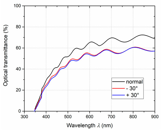
Figure 4.
An example of optical transmittance spectra in the visible range of 1 µm thick WO3 zigzag thin film prepared on glass substrate with a number of zigzags N = 0.5. The film was deposited with a tilt angle α = 85° and a duty cycle dc = 80% of the pulsing period P. 3 different angles of the incidence beam were used by the spectrometer: normal incidence (black), −30° (red), and +30° (blue).
Optical transmittance spectra in the visible range of the films deposited on glass substrate were used to determine the evolution of refractive index vs. wavelength by means of the Swanepoel’s method involving measurements of the optical transmission vs. wavelength at normal incidence (0°) and at oblique incidence angles (±30°) [30]. Refractive index in the visible range of all zigzag WO3 films exhibit a typical Cauchy’s dispersion law (Figure 5). Whatever the number of zigzags, the film ‘s index is lower than that of the WO3 bulk value (n589 = 2.50 at 589 nm [39]). This is mainly assigned to the porous architecture commonly reported in oxide thin films prepared by GLAD, and exhibiting tilted columns, zigzags, or helices [40]. The shadowing effect induced by the high deposition angle (α = 80°) and the periodic change of ϕ angle (180° rotations) to produce zigzag columns both favor the growth of a voided microstructure.
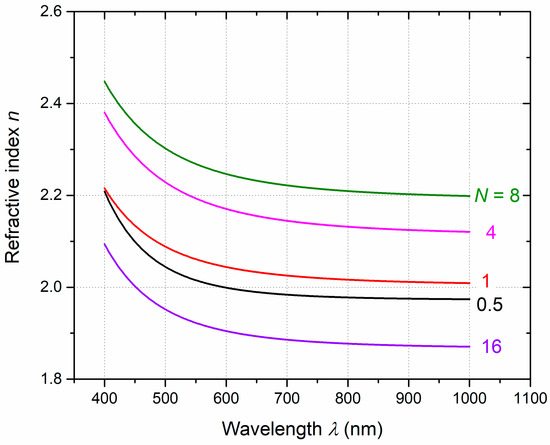
Figure 5.
Refractive index as a function of the wavelength of 1 µm thick WO3 zigzag thin films sputter-deposited on glass substrate with various numbers of zigzags (N = 0.5 to 16). All films were obtained with a tilt angle α = 80° and a duty cycle dc = 80% of the pulsing period P.
It is also worth of noting that the number of zigzags strongly influences the refractive index. The lowest indices are obtained for N = 16 and N = 0.5 (tilted columns as shown in Figure 2a) with n589 below 2.0. In contrast, the highest refractive indices are produced for WO3 films exhibiting N = 4 and 8 zigzags through the thickness of 1 µm. This optimized refractive index of WO3 thin films exhibiting a zigzag columnar architecture for a number of zigzags close to 4–8 agrees with former experimental and simulated optical properties of tungsten oxide nanostructured thin films [41]. As a result, optical properties, and thus the films’ density can be tuned and optimized by a simple adjustment of the number of zigzags (cf. Section 3.3 for correlating with the microstructure).
The Swanepoel’s method was also used to determine extinction and absorption coefficients of WO3 zigzag films as a function of the number of zigzags, and for a given wavelength (Figure 6). Both coefficients exhibit the same trend as the number of zigzags increases, i.e., a continuous reduction as N changes from 0.5 to 16. However, films containing the lowest number of zigzags (0.5 < N < 4) show the highest extinction and absorption coefficients, as well as the most significant drop vs. N. These two coefficients are connected to each other and directly represent how easily a volume of material can be penetrated by the light. As a result, these high coefficient values mean a strong attenuation of the beam light when crossing the zigzag structure. Reducing the number of zigzags down to N = 0.5, WO3 films give rise to a tilted columnar architecture with column broadening effect and an increase of surface roughness as the film’s thickness or the column angle increases [42]. Basically, the termination of the slanted nanocolumns at the film surface produces an unusual topography, which is characterized by a high surface roughness [43].
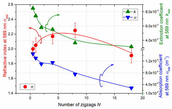
Figure 6.
Refractive index, extinction coefficient, and absorption coefficient at 589 nm of WO3 films vs. number of zigzags N. All films were sputter-deposited with a tilt angle α = 80° and a duty cycle dc = 80% of the pulsing period P. Fit lines are used to guide the eye.
As the deposition angle α rising from 0 to 85°, typical RMS (root-mean-square) roughness ranging from a few nm to more than 20 nm have been reported for GLAD thin films produced by evaporation or magnetron sputtering [44]. This high surface roughness favors the light scattering at the air/film interface and thus contributes to the high extinction and absorption coefficients. By increasing the number of zigzags, the length of a single zigzag reduces. Assuming Backholm et al. investigation [45], RMS roughness significantly drops when the length scale (dimension of a single zigzag) is lower than 100 nm and becomes below 2–3 nm as the length scale decreases down to a few nm.
It is also important to notice that reduction of extinction and absorption coefficients is not so noticeable as the number of zigzags is higher than 4. This smooth decrease for N > 4 also corresponds to the maximum of refractive index (Figure 6). A more voided structure is produced, and the films become more transparent.
3.3. Microstructure vs. Refractive Index
Refractive index of zigzag WO3 films prepared with three deposition angles (α = 75°, 80·and 85°) has been systematically calculated at 589 nm and as a function of the number of zigzags (Figure 7). Whatever the deposition angle, all films exhibit the same evolution of refractive index vs. N, i.e., a maximum value around N = 4. In addition, refractive index is always lower than that of WO3 film prepared by conventional sputtering (α = 0°). An increase of the deposition angle from 70° to 85° steadily shifts indices to lower values for all numbers of zigzags. This trend has ever been reported for WO3 films exhibiting a tilted columnar architecture [46]. It is mainly ascribed to the growth of a more porous structure as the deposition angle rises. The shadowing effect is emphasized for high deposition angles, which leads to higher amounts of voids in the films, and thus a decrease in the overall film’s density. For zigzags, a similar explanation can be suggested for discussing this drop of refractive index vs. deposition angle. However, the number of zigzags also influences the optical properties and thus, the peculiar growth and geometry of zigzags architecture has to be considered for understanding these optimized refractive indices close to N = 4.
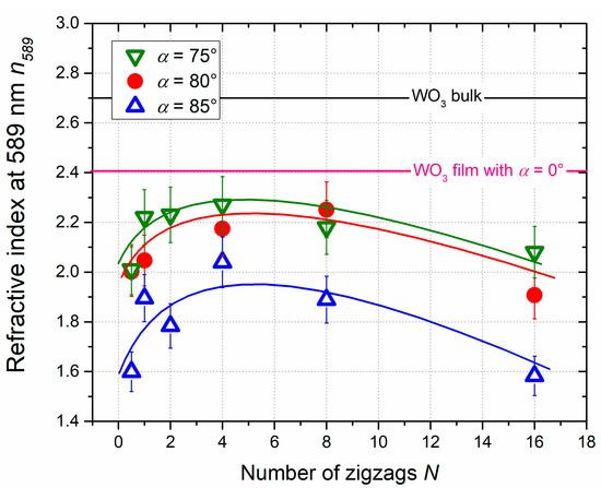
Figure 7.
Refractive index at 589 nm of WO3 films vs. number of zigzags N. All films were sputter-deposited with a duty cycle dc = 80% of the pulsing period P and for tilt angles α = 75°, 80°, and 85°. Refractive index of bulk WO3 material and standard WO3 film (α = 0° and without oxygen pulsing, i.e., dc = 100% of the pulsing period P) is also indicated. The lines are a guide to the eye.
Because of the change in the growing direction at every 180° ϕ rotation, such a change disturbs the widening of the column cross-section and thus interrupts the shadowing effect from arm to arm. After the first growing stage, the subsequent column arms grow on the column apex and partially on the columns side previously located in the shadowing zone. It somewhat fills the serrated zone, voids, and defects created by the preceding growth interval [47]. This partial filling of the defecting growth, roughness, and porosities on a part of the columns becomes more and more significant when the number of zigzags increases (i.e., N > 2 in our study). The voided structure of a given column is reduced and the films tend to be denser.
As the number of zigzags increases, the 180° ϕ rotation becomes more frequent and leads to a less and less undistinguishable zigzag shape of the columnar structure. As-deposited architecture looks like a field of columns perpendicular to the substrate surface with large spaces between columns (as shown in Figure 2f). By shortening the growth interval of each arm, the incident vapor cannot fully form a new arm and the structure gradually broadens. It is also interesting to note that the GLAD film porosity strongly depends on the thickness. As previously reported by Amassian et al. [48], a transition occurs from a high coverage film to a porous film during the first growing stage (first monolayers) and above 1 nm of deposition. Shadowing phenomenon prevails over smoothing effects due to surface diffusion of atoms impinging on the columns. For the highest number of zigzags, the shadowing length reduces and for each new grow direction, the formation of a new arm vanishes. A new column nucleates at the start of each grow interval and produces a nearly constant column width preventing columns extinction.
This atypical growth of zigzag architectures also influences shape and dimension of the resulting porous structure, as suggested by Hass et al. [34,35]. These authors proposed the occurrence of three types of pores. The largest pores (type I) with a width exceeding 0.3 µm separating primary growth columns that are a few µm in width (intermediate columns of about 1 µm width exist within the primary columns). They are bounded by narrower type II pores that are ~0.1 µm wide. Finally, type III pores of ~20 nm width existing between even finer growth columns (20–80 nm in width) present within the secondary growth columns. These type III pores are usually discontinuous. The same authors showed that the thermal conductivity of zigzag films exhibits a minimum value as a function of the number of zigzags, as also reported by Amaya et al. [49]. They assigned this minimum value to the type I pores, which have a longer wavelength and greater inclination angle than type II and III pores. As a result, type I pores mainly rule heat flow propagation through the zigzag films thickness. Assuming such an approach, the analogy can be suggested for explaining the maximum of refractive index that we systematically obtained in zigzag WO3 thin films for a number of zigzags around 4. For the smallest numbers of zigzags (N < 2), the type I pores wavelength is higher corresponding to a high porous structure, and thus a low refractive index (type II and III pores also contribute to lower the refractive index). For the highest numbers of zigzags (N > 8), type I pores tend to be perpendicular to the substrate surface (contribution from type II and II pores become negligible) with a pore amplitude larger than the columns width, and so, a reduction of the films refractive index.
4. Conclusions
WO3 thin films 1 µm thick exhibiting a zigzag columnar architecture were produced by magnetron reactive sputtering combining GLancing Angle Deposition (GLAD) and Reactive Gas Pulsing Process (RGPP). The number of zigzags was systematically changed from 0.5 to 16 leading to a tunable zigzag architecture with adjustable arm lengths. For the shortest numbers of zigzags, a series of column arms with alternating growth direction was clearly produced, whereas a reduction of growth interval between each 180° ϕ rotation (highest numbers of zigzags) led to single vertically oriented columns.
Optical properties were investigated, especially refractive index, extinction, and absorption coefficient in the visible range. Both coefficients exhibited a continuous decrease as a function of the number of zigzags. It was mainly assigned to the high surface roughness favoring the light scattering at the air/film interface particularly when the number of zigzags changed from 0.5 to 4.
WO3 zigzag films prepared with the highest deposition angle (α = 85°) gave rise to the lowest refractive indices because of the largest voided structure mostly produced as the deposition angle tend to the most grazing incidence. Refractive index interestingly showed a maximum value as a function of the number of zigzags whatever the deposition angle (α = 70°, 80°, or 85°). A correlation was proposed between this optimized optical characteristic and the hierarchical pore structure, especially the width and the inclination of the biggest pores between zigzags as a function of their number. As a result, such a zigzag architecture appears as an original way to precisely tune the optical properties of metallic oxide thin films and can be certainly extended to other properties.
Author Contributions
C.S.: Data Curation. J.-Y.R.: Resources. J.-M.C.: Software. V.T.: Resources. J.G.: Formal analysis. N.M.: Writing—Review and Editing. All authors have read and agreed to the published version of the manuscript.
Funding
This work has been supported by the Region Bourgogne Franche-Comté and by EIPHI Graduate School (contract “ANR-17-EURE-0002”).
Institutional Review Board Statement
Not applicable.
Informed Consent Statement
Not applicable.
Data Availability Statement
All data are presented in the current manuscript.
Conflicts of Interest
The authors declare no conflict of interest. The founding sponsors had no role in the design of the study; in the collection, analyses, or interpretation of data; in the writing of the manuscript, or in the decision to publish the results.
References
- Nie, Z.; Kumacheva, E. Patterning surfaces with functional polymers. Nat. Mater. 2008, 7, 277–290. [Google Scholar] [CrossRef]
- Wang, A.X.; Kong, X. Review of recent progress of plasmonic materials and nano-structures for surface-enhanced raman scattering. Materials 2015, 8, 3024–3052. [Google Scholar] [CrossRef] [PubMed]
- Gong, Y.; Yang, S.; Zhan, L.; Ma, L.; Vajtai, R.; Ajayan, P.M. A bottom-up approach to build 3D architectures from nanosheets for superior lithium storage. Adv. Funct. Mater. 2013, 24, 125–130. [Google Scholar] [CrossRef]
- Gregorczyk, K.; Knez, M. Hybrid nanomaterials through molecular and atomic layer deposition: Top down, bottom up, and in-between approaches to new materials. Prog. Mater. Sci. 2016, 75, 1–37. [Google Scholar] [CrossRef]
- Chen, Y.; Xu, Z.; Gartia, M.R.; Whitlock, D.; Lian, Y.; Liu, G.L. Ultrahigh throughput silicon nanomanufacturing by simultaneous reactive ion synthesis and etching. ACS Nano 2011, 5, 8002–8012. [Google Scholar] [CrossRef] [PubMed]
- Caglar, M.; Ilican, S.; Caglar, Y.; Yakuphanoglu, F. Electrical conductivity and optical properties of ZnO nanostructured thin film. Appl. Surf. Sci. 2009, 255, 4491–4496. [Google Scholar] [CrossRef]
- Mark, A.G.; Gibbs, J.G.; Lee, T.-C.; Fischer, P. Hybrid nanocolloids with programmed three-dimensional shape and material composition. Nat. Mater. 2013, 12, 802–807. [Google Scholar] [CrossRef] [PubMed]
- Raveh, A.; Zukerman, I.; Shneck, R.; Avni, R.; Fried, I. Thermal stability of nanostructured superhard coatings: A review. Surf. Coatings Technol. 2007, 201, 6136–6142. [Google Scholar] [CrossRef]
- Cao, F.; McEnaney, K.; Chen, G.; Ren, Z. A review of cermet-based spectrally selective solar absorbers. Energy Environ. Sci. 2014, 7, 1615–1627. [Google Scholar] [CrossRef]
- Zhang, Q.; Wang, J.; Dong, J.; Ding, F.; Li, X.; Zhang, B.; Yang, S.; Zhang, K. Facile general strategy toward hierarchical mesoporous transition metal oxides arrays on three-dimensional macroporous foam with superior lithium storage properties. Nano Energy 2015, 13, 77–91. [Google Scholar] [CrossRef]
- Gesheva, K.; Ivanova, T.; Bodurov, G. Transition metal oxide films: Technology and “Smart Windows” electrochromic device performance. Prog. Org. Coat. 2012, 74, 635–639. [Google Scholar] [CrossRef]
- Xu, X.; Pour Yazdi, M.A.; Sanchez, J.-B.; Billard, A.; Berger, F.; Martin, N. Exploiting the dodecane and ozone sensing capabilities of nanostructured tungsten oxide films. Sens. Actuators B: Chem. 2018, 266, 773–783. [Google Scholar] [CrossRef]
- Kulkarni, S.B.; Mane, A.T.; Navale, S.T.; Kulkarni, P.S.; Mulik, R.N.; Patil, V.B. Synthesis, structural, compositional, morphological and optoelectronic properties of tungsten oxide thin films. J. Mater. Sci. Mater. Electron. 2014, 26, 1087–1096. [Google Scholar] [CrossRef]
- Castillo, R.H.; Peñuñuri, F.; Canto-Reyes, D.; Pool, A.B.; Mendez-Gamboa, J.; Acosta, M. Electrical percolation threshold evaluation of silver thin films for multilayer WO3/Ag/WO3 transparent conductive oxide. Mater. Lett. 2020, 260, 126913. [Google Scholar] [CrossRef]
- Yuan, J.; Wang, B.; Wang, H.; Chai, Y.; Jin, Y.; Qi, H.; Shao, J. Electrochromic behavior of WO3 thin films prepared by GLAD. Appl. Surf. Sci. 2018, 447, 471–478. [Google Scholar] [CrossRef]
- Yao, S.; Zhu, Y. Nanomaterial-enabled stretchable conductors: Strategies, materials and devices. Adv. Mater. 2015, 27, 1480–1511. [Google Scholar] [CrossRef] [PubMed]
- Zheng, J.; Yang, R.; Xie, L.; Qu, J.; Liu, Y.; Li, X. Plasma-assisted approaches in inorganic nanostructure fabrication. Adv. Mater. 2010, 22, 1451–1473. [Google Scholar] [CrossRef] [PubMed]
- Robbie, K.; Brett, M.J. Sculptured thin films and glancing angle deposition: Growth mechanics and applications. J. Vac. Sci. Technol. A 1997, 15, 1460–1465. [Google Scholar] [CrossRef]
- Panepinto, A.; Snyders, R. Recent advances in the development of nano-sculpted films by magnetron sputtering for energy-related applications. Nanomaterials 2020, 10, 2039. [Google Scholar] [CrossRef]
- Zhao, Y.; Ye, D.; Wang, G.-C.; Lu, T.-M. Designing nanostructures by glancing angle deposition. Nanotub. Nanowires 2003, 5219, 59–74. [Google Scholar] [CrossRef]
- Huang, Z.; Bai, F. Wafer-scale, three-dimensional helical porous thin films deposited at a glancing angle. Nanoscale 2014, 6, 9401–9409. [Google Scholar] [CrossRef] [PubMed]
- El Beainou, R.; Martin, N.; Potin, V.; Pedrosa, P.; Pour Yazdi, M.A.; Billard, A. W-Cu sputtered thin films grown at oblique angles from two sources: Pressure and shielding effects. Surf. Coat. Technol. 2018, 343, 153–159. [Google Scholar] [CrossRef]
- Qu, Y.; Zhang, Z.; Fu, T.; Wang, G.; Wang, T.; Wang, M.; Bai, Y.; Zhang, Z. Dielectric tuned circular dichroism of L-shaped plasmonic metasurface. J. Phys. D: Appl. Phys. 2017, 50, 504001. [Google Scholar] [CrossRef]
- Khare, C.; Stepanovich, A.; Buenconsejo, P.J.S.; Ludwig, A. Synthesis of WO3 nanoblades by the dealloying of glancing angle deposited W-Fe nanocolumnar thin films. Nanotechnology 2014, 25, 205606. [Google Scholar] [CrossRef]
- Larbi, A.; Akkari, F.C.; Dahman, H.; Demaille, D.; Gallas, B.; Kanzari, M. Structural, morphological and optical properties of Sn3Sb2S6 thin films synthesized by oblique angle deposition. J. Electron. Mater. 2016, 45, 5487–5496. [Google Scholar] [CrossRef]
- Wang, S.; Xia, G.; Fu, X.; He, H.; Shao, J.; Fan, Z. Preparation and characterization of nanostructured ZrO2 thin films by glancing angle deposition. Thin Solid Films 2007, 515, 3352–3355. [Google Scholar] [CrossRef]
- Park, Y.J.; Sobahan, K.M.A.; Hwangbo, C.K. Optical and structural properties of a circular polarizationhandedness inverter prepared by using glancing angle deposition. J. Korean Phys. Soc. 2009, 55, 1263–1266. [Google Scholar] [CrossRef]
- Martin, N.; Lintymer, J.; Gavoille, J.; Chappé, J.; Sthal, F.; Takadoum, J.; Vaz, F.; Rebouta, L. Reactive sputtering of TiOxNy coatings by the reactive gas pulsing process. Surf. Coatings Technol. 2007, 201, 7727–7732. [Google Scholar] [CrossRef]
- Xu, X.; Pour Yazdi, M.A.; Salut, R.; Cote, J.-M.; Billard, A.; Martin, N. Structure, composition and electronic transport properties of tungsten oxide thin film sputter-deposited by the reactive gas pulsing process. Mater. Chem. Phys. 2018, 205, 391–400. [Google Scholar] [CrossRef]
- Swanepoel, R. Determining refractive index and thickness of thin films from wavelength measurements only. J. Opt. Soc. Am. A 1985, 2, 1339–1343. [Google Scholar] [CrossRef]
- Tait, R.; Smy, T.; Brett, M. Modelling and characterization of columnar growth in evaporated films. Thin Solid Films 1993, 226, 196–201. [Google Scholar] [CrossRef]
- Hawkeye, M.M.; Taschuk, M.T.; Brett, M.J. Glancing Angle Deposition of Thin Films; John Wiley & Sons Ltd: Chichester, UK, 2014; p. 61. [Google Scholar]
- Karabacak, T.; Singh, J.P.; Zhao, Y.-P.; Wang, G.-C.; Lu, T.-M. Scaling during shadowing growth of isolated nanocolumns. Phys. Rev. B 2003, 68, 125408. [Google Scholar] [CrossRef]
- Gu, S.; Lu, T.J.; Hass, D.D.; Wadley, H.N.G. Thermal conductivity of zirconia coatings with zig-zag pore microstructures. Acta Mater. 2001, 49, 2539–2547. [Google Scholar] [CrossRef]
- Hass, D.; Slifka, A.; Wadley, H. Low thermal conductivity vapor deposited zirconia microstructures. Acta Mater. 2001, 49, 973–983. [Google Scholar] [CrossRef]
- Charles, C.; Martin, N.; Devel, M.; Ollitrault, J.; Billard, A. Correlation between structural and optical properties of WO3 thin films sputter deposited by glancing angle deposition. Thin Solid Films 2013, 534, 275–281. [Google Scholar] [CrossRef]
- Charles, C.; Martin, N.; Devel, M. Optical properties of WO3 thin films modeled by finite-difference time-domain and fabricated by glancing angle deposition. J. Nanosci. Nanotechnol. 2012, 12, 9125–9130. [Google Scholar] [CrossRef] [PubMed]
- Dolatshahi-Pirouz, A.; Hovgaard, M.B.; Rechendorff, K.; Chevallier, J.; Foss, M.; Besenbacher, F. Scaling behavior of the surface roughness of platinum films grown by oblique angle deposition. Phys. Rev. B 2008, 77, 115427. [Google Scholar] [CrossRef]
- Sawada, S.; Danielson, G.C. Optical indices of refraction of WO3. Phys. Rev. 1959, 113, 1008–1013. [Google Scholar] [CrossRef]
- Steele, J.J.; Brett, M.J. Nanostructure engineering in porous columnar thin films: Recent advances. J. Mater. Sci. Mater. Electron. 2007, 18, 367–379. [Google Scholar] [CrossRef]
- Charles, C.; Martin, N.; Devel, M. Optical properties of nanostructured WO3 thin films by GLancing Angle Deposition: Comparison between experiment and simulation. Surf. Coat. Technol. 2015, 276, 136–140. [Google Scholar] [CrossRef]
- Wang, S.; Fu, X.; Xia, G.; Wang, J.; Shao, J.; Fan, Z. Structure and optical properties of ZnS thin films grown by glancing angle deposition. Appl. Surf. Sci. 2006, 252, 8734–8737. [Google Scholar] [CrossRef]
- Lintymer, J.; Gavoille, J.; Martin, N.; Takadoum, J. Glancing angle deposition to modify microstructure and properties of sputter deposited chromium thin films. Surf. Coat. Technol. 2003, 174-175, 316–323. [Google Scholar] [CrossRef]
- Barranco, A.; Borras, A.; Gonzalez-Elipe, A.R.; Palmero, A. Perspectives on oblique angle deposition of thin films: From fundamentals to devices. Prog. Mater. Sci. 2016, 76, 59–153. [Google Scholar] [CrossRef]
- Backholm, M.; Foss, M.; Nordlund, K. Roughness of glancing angle deposited titanium thin films: an experimental and computational study. Nanotechnology 2012, 23, 385708. [Google Scholar] [CrossRef] [PubMed]
- Rydosz, A.; Dyndał, K.; Kollbek, K.; Andrysiewicz, W.; Sitarz, M.; Marszałek, K. Structure and optical properties of the WO3 thin films deposited by the GLAD magnetron sputtering technique. Vacuum 2020, 177, 109378. [Google Scholar] [CrossRef]
- El Beainou, R.; Garcia-Valenzuela, A.; Raschetti, M.; Cote, J.-M.; Alvarez, R.; Palmero, A.; Potin, V.; Martin, N. A 4-view imaging to reveal microstructural differences in obliquely sputter-deposited tungsten films. Mater. Lett. 2020, 264, 127381. [Google Scholar] [CrossRef]
- Amassian, A.; Kaminska, K.; Suzuki, M.; Martinu, L.; Robbie, K. Onset of shadowing-dominated growth in glancing angle deposition. Appl. Phys. Lett. 2007, 91, 173114. [Google Scholar] [CrossRef]
- Amaya, C.; Prıas-Barragan, J.J.; Caicedo, J.C.; Yañez-Limon, J.M.; Zambrano, G. Impact of the Glancing Angle Deposition on the Yttria-Stabilized Zirconia Growth and Their Thermal Barrier Coating Properties, Chapter 8. In Coatings and Thin-Film Technologies by J.A. Perez Taborda and A. Avila; IntechOpen: London, UK, 2019. [Google Scholar] [CrossRef]
Publisher’s Note: MDPI stays neutral with regard to jurisdictional claims in published maps and institutional affiliations. |
© 2021 by the authors. Licensee MDPI, Basel, Switzerland. This article is an open access article distributed under the terms and conditions of the Creative Commons Attribution (CC BY) license (https://creativecommons.org/licenses/by/4.0/).