Abstract
Novel nonlinear power-law flux models were utilized to model the heat transport phe-nomenon in nano-micropolar fluid over a flexible surface. The nonlinear conservation laws (mass, momentum, energy, mass transport and angular momentum) and KKL cor-relations for nanomaterial under novel flux model were solved numerically. Computed results were used to study the shear-thinning and shear-thickening nature of nano pol-ymer suspension by considering n-diffusion theory. Normalized velocity, temperature and micro-rotation profiles were investigated under the variation of physical parame-ters. Shear stresses at the wall for nanoparticles (CuO and Al2O3) were recorded and dis-played in the table. Error analyses for different physical parameters were prepared for various parameters to validate the obtained results.
1. Introduction
Polymer liquids like suspensions are non-Newtonian liquids containing solid-like microstructure. The rheology of such suspensions is characterized by two types of stress–strain correlations (i) the stress–strain correlations associated with macromotion caused by the body and surface forces and (ii) couple stress–strain constitutive equations based on micro-rotations of solid structures immersed in the suspension. Eringen [1] was the first to introduce the theory of such fluids and named them “micropolar fluids” (MF). After Eringen, many investigations were carried out to analyze several phenomena like heat transfer [2,3], mass transfer [4,5], viscous dissipation [6,7], Joule heating [8], Hall and ion slip effects [9], the effect of dispersion of nanoparticles [10,11], Soret and Dufour effects [12], using MF theory. The studies mentioned in refs. [13,14] are based on classical linear flux models, which assume that the diffusion coefficients are constant. However, Peter et al. [15] showed that the spinning of solid particles immersed in base liquid has a significant effect on viscosity effectiveness. This development motivated the researchers to establish novel nonlinear constitutive models for MF and, in view of suggestions by Peter et al. [15] and Sui et al. [16], proposed a novel similar nonlinear fluidic system. The generalized n- diffusion theory [17] is utilized by Sui et al. [16] to capture shear-thinning and shear-thickening performances. For more clarity, the following Table 1 is given for the comparison between classical and novel flux models.

Table 1.
Comparison between classical and novel models.
The expression and are termed apparent thermal conductivity, apparent dynamic viscosity & apparent vortex viscosity, respectively. Further, for is the case of the shear-thinning nature of the liquid. It is noted that for the power index, the novel flux models reduce to the classical Fourier law of heat conduction and classical stress–strain relations for MF. Moreover , the novel models capture shear-thickening behavior. Theoretical and experimental works on an enhancement of heat transfer through the dispersion of nanosolid particles in liquids motivated researchers and to invent several correlations for effective (viscosity, thermal properties and thermal conductivity etc.,) Among them example, the latest model is by Koo, Kleinstreuer and Li (KKL). Researchers have studied this model in recent years to present and analyze several applications in the field of science and technology. For instance, Kandelousi [18] and Haq et.al. [19] presented applications of KKL model in different geometries, while Alsagri and Moradi [20] presented some applications of the KKL nanoliquid model. They discussed some applications of nanofluid in heat transfer problems between rotary tubes. Rana and Nawaz [21] investigated the enhancement of heat transfer in Sutterby nanoliquid by analyzing the Koo–Kleinstreuer and Li (KKL) correlations. They also studied the generalized heat fluxes via Cattaneo–Christov heat flux model. An optimization via a numerical approach of microchannel heat sink (MCHS) performance utilizing the KKL theory has been analyzed by Pourmehran et al. [22]. Vijaybabu [23] computed the entropy generation and influence of permeable circular geometry by considering the nanofluids through KKL theory. Haq and Aman [24] analyzed the heated trapezoidal cavity with inner-heated obstacles with the KKL nanoliquid model. Multiple results for hydromagnetic Jeffery–Hamel flow utilizing KKL nanofluid model is studied by Rana et al. [25] Sheikholeslami and Mahian [26] presented application in energy storage through KKL theory by studying the enhancement of PCM solidification using inorganic nanomaterial. Mehmood et al. [27] studied simulations of hydromagnetic convective rheology in a square porous cavity using the KKL model. Li et al. [28] presented the applications of CVFEM for nanofluid heat transfer intensification by studying the KKL nano liquid model. Computational modeling of curved geometry with Koo–Kleinstreuer and Li (KKL) correlation model has been studied by Gowda et al. [29]. The relations utilized are:
Thermophysical properties of water and two types of metallic nanoparticles, which are used by Sheikholeslami [30], are given in Table 2.
Table 2.
Thermophysical properties of water and nanoparticles.
2. Physical Situation
We investigated the effects of dispersion of nanoparticles (CuO and Al2O3) on the performance of thermal conductivity and viscosity using the KKL model. Mass, linear momentum, angular momentum and thermal diffusion, and boundary layers models are:
where is for the velocity of the fluid, is for the microrotations or angular velocity in the xy plane, and T is for the temperature of the fluid. The other physical quantities and are the density and thermal conductivity, respectively. In this study, the Spin gradient viscosity is defined as such that where
The following boundary conditions:
are implemented for the solution of modeled boundary problems.
Normalization of equations: Diffusion Equations (9)–(12) and initial and boundary conditions (8a) are made dimensionless using the following transformations:
and hence we get the following boundary value problems:
where:
Expressions for the wall skin friction and Nusselt number are given below:
where:
3. Numerical Procedure
Here, a brief and complete description of the numerical approaches Adams and explicit Runge–Kutta (RK) methods to solve heat transport phenomenon in nano-micropolar polymer over a flexible surface (15)–(17) is presented.
Adam Predictor—Corrector Solver
The heat transport phenomenon in nano-micropolar polymer over a flexible surface is represented in Equations (15)–(17) and is transformed in to equivalent first-order differential system along with boundary conditions in terms of the velocity field , , temperature profile .
Generic representations of a derived first-order system for , and are given, respectively, as follows:
The generalized expressions for two-stage Adams predictor–corrector technique [31,32,33,34,35,36] for , and are given, respectively, as follows:
where h is a step size parameter. Accordingly, standard multi-stage Adams predictor-corrector expressions for , and are illustrated, respectively, as follows:
4. Results and Discussion
In this section, we present and discuss the behavior of several involved physical quantities on the flow field by utilizing the numerical values given in Table 3. Several graphs were prepared to analyze the absolute error in computation. Moreover, a comparison of obtained solutions via the Adams method and explicit Runge–Kutta method is also presented. A good agreement between the solutions is noted, which validates the precision of obtained results. The graphical and tabular results are presented to show the effects of physical parameters. In this regard, Figure 1, Figure 2, Figure 3, Figure 4, Figure 5, Figure 6, Figure 7, Figure 8, Figure 9, Figure 10, Figure 11, Figure 12, Figure 13 and Figure 14 were plotted to analyze the effects of the involved physical parameter when CuO nanoparticles are suspended in the base fluid. Figure 1 presents the effects of k0 on the velocity profile . It is noted that velocity field retard for positive values of k0. The momentum boundary layer also decreases with an increase in k0. The solid curves present the solutions via the Adams method, whereas bullets represent the results for the explicit Runge–Kutta method. Both solutions were found to be in good agreement.
Table 3.
The coefficient values of CuO and Al2O3 nanofluids.
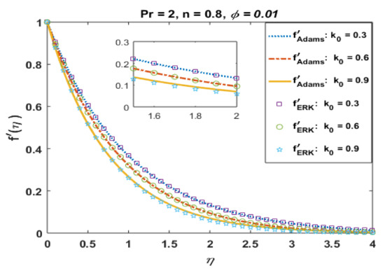
Figure 1.
Effects of k0 on .
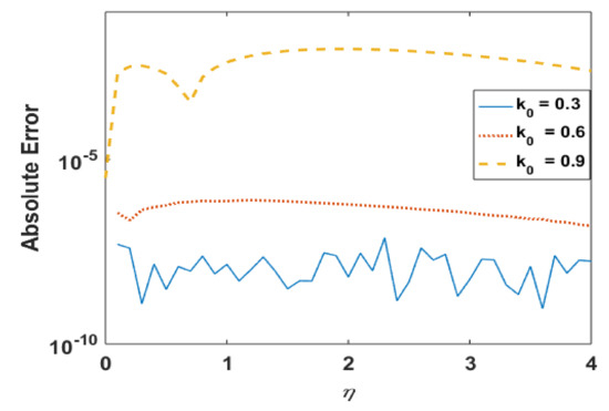
Figure 2.
Absolute error in for different k0.
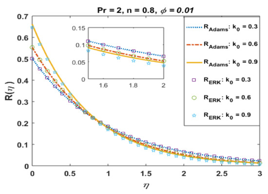
Figure 3.
Effects of k0 on .
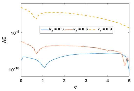
Figure 4.
Absolute error in on different k0.
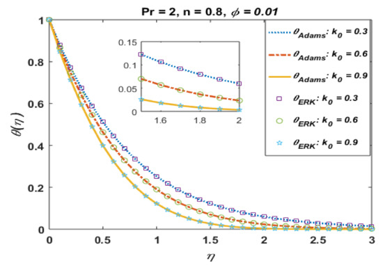
Figure 5.
Effects of k0 on .
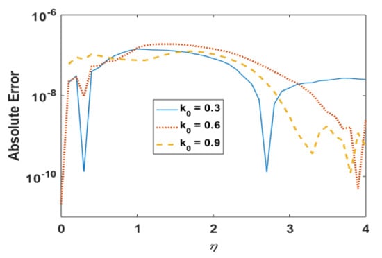
Figure 6.
Absolute error in for different k0.
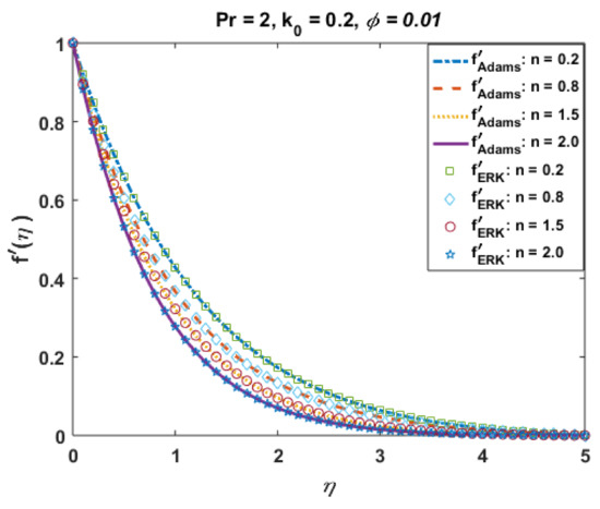
Figure 7.
Effects of n on .
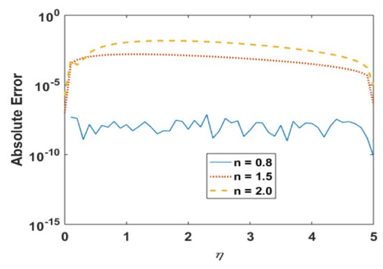
Figure 8.
Absolute error in for different n.
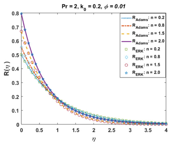
Figure 9.
Effects of n on .
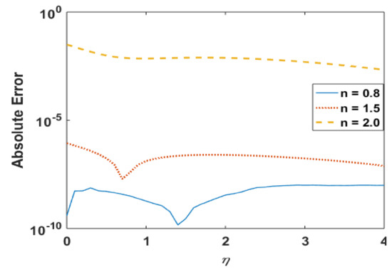
Figure 10.
Absolute error in for different n.
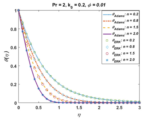
Figure 11.
Influence of n on .
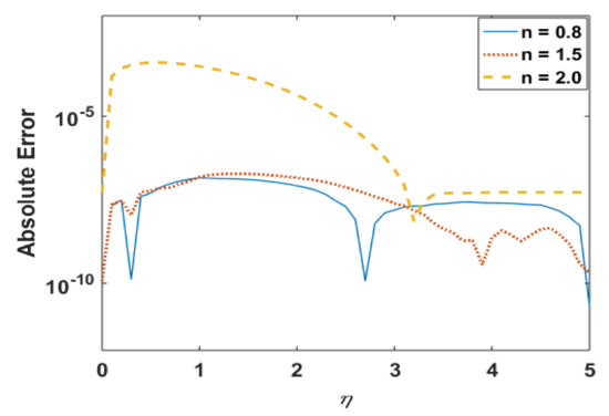
Figure 12.
Absolute error in for different n.
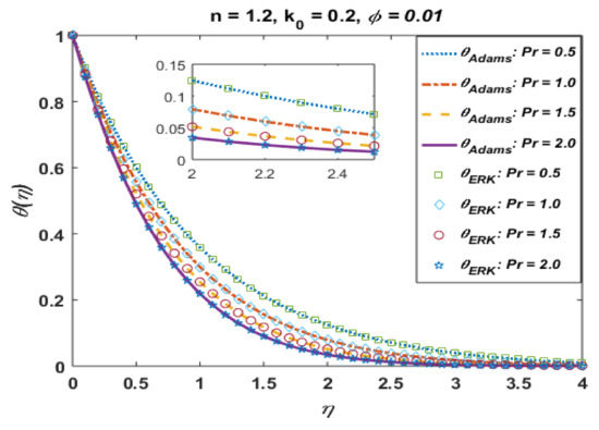
Figure 13.
Effects of Pr on .
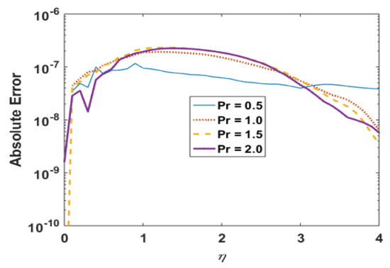
Figure 14.
Absolute error in for different Pr.
Figure 2 presents the absolute error for different values of k0. It is noted that the error in computations is approximately 10−8. Figure 3 portrays the effects of k0 on R. It is noted the profile R decreases near the boundary but demonstrates the opposite trend away from the wall. This is obvious to obey the mass conservation constraint. The absolute error in profile R is presented in Figure 4, which confirmations that the error is minimum to the tolerance level.
Figure 5 and Figure 6 present the effects of k0 on temperature profile and the absolute error in computations. It is observed that the temperature profile was found to decrease with an increase in k0. Moreover, solutions obtained via the Adams method and explicit Runge–Kutta is also in good agreement, and the absolute error is also found to be negligible.
Figure 7 portrays the effects of shear-thinning/thickening parameter “n” on the velocity profile . The case (n < 1.0) represents the reduction in viscosity with the shear rate or shear-thinning effects, whereas the case (n > 1.0) shows the increase in viscosity with the shear rate or shear-thickening effect. The plot elucidates that the velocity field increases for the case when n decreases from numerical value 1.0, whereas it decreases for the case when n increases from numerical value 1.0.
Such outcomes illustrate that the more shear-thinning/thickening effects will be observed when the values different from n = 1.0 are considered. From a physical point of view, it is clear that an apparent decrease/increase in viscosity of the suspended micropolar material is accredited to the rotation of particles and for increasing/decreasing values of “n”, the shear-thinning/thickening effects due to the microparticle rotation represents the layer-by-layer fluid separation, which results in the momentum boundary layer thinned/thickened for different n. The solutions via Adam and explicit RK are also in good agreement, and the absolute error (Figure 8) is also negligible.
Figure 9 presents the effects of “n” on profile micro-rotation velocity field R via Adams and explicit RK since the particle angular velocity distribution profiles is a significant factor in micropolar fluid rheology. This plot signifies the exclusive micro-rotation velocity profiles for the shear-thinning/thickening phenomenon portrayed by “n”. It is also observed that the microrotation velocity field retards at the boundary and reaches the numerical values of 0.0 at the boundary layer. The profiles consequently overlap each other, as noted in the figure. The granular velocity decreasing rate is minor near the wall and signifies the boundary layer. The absolute error plot (Figure 10) also shows negligible error up to the tolerance level.
Figure 11 presents the effects of n on the temperature profile . This plot shows that the temperature profile decays with an increase in n. The temperature field thickens for smaller values of “n”, which not only be contingent on heat conduction performance of micropolar fluid demonstrated by reformed thermal conductivity properties but also to a great magnitude on the shear-thinning consequence as a dynamical property in shear flow. Moreover, solutions via Adams and explicit RK are also in good agreement. Figure 12 portrays the absolute error is computed results for different values and noted that error is negligible. Figure 13 is prepared to interpret the effects of the Prandtl number Pr on the temperature profile. This graph shows that temperature retards for positive values of Pr. Moreover, absolute error (Figure 14) is also found to be negligible. Table 4 is prepared to analyze the values for skin friction and the local Nusselt number for different physical quantities.
Table 4.
Behavior of skin friction and Nusselt number when and .
Figure 15 presents the effects of k0 on the velocity profile for the suspension of alumina nanoparticles. It is observed that velocity profiles accelerate for the positive values of k0. Moreover, thermal boundary layers also increase with an increase in k0. The solutions obtained via the Adams method are in good agreement with the results of ERK. The effects of k0 on R are portrayed in Figure 16. It is noted that jump effects were noted at the wall for positive values of k0, whereas an opposite trend is noted after the region .
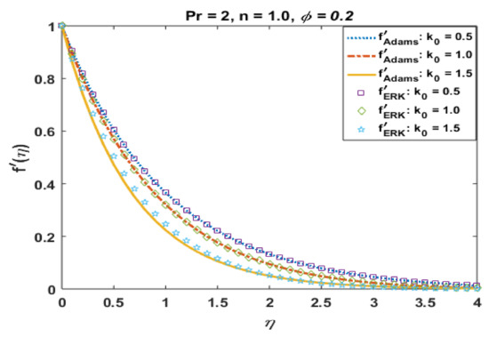
Figure 15.
Effects of k0 on .
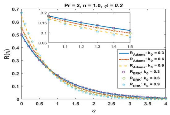
Figure 16.
Effects of k0 on .
The effects of k0 on temperature profile are elucidated in Figure 17. It is observed that temperature and thermal boundary layer reduced with an increase in k0. The micro-rotation parameter “n” retards the flow and boundary layer, as noted in Figure 18. The results for CuO and Al2O3 are qualitatively similar.
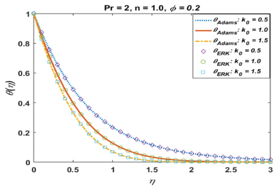
Figure 17.
Effects of k0 on .
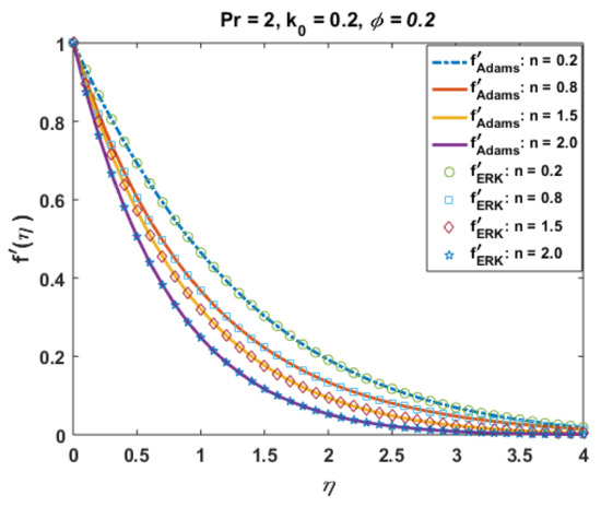
Figure 18.
Effects of n on .
Effects of n on profiles R and are portrayed in Figure 19 and Figure 20. From these plots, one can see the jump effects are noted for larger values of n against R and the opposite trend is noted far from the surface, whereas temperature and thermal boundary layer retards for positive values of n. The effects of the Prandtl number Pr on temperature are presented in Figure 21. It is noted that the temperature and thermal boundary layer decrease with an increase in Pr. From the plotted graphs, it is noted that the results of CuO suspension are qualitatively similar to those of Al2O3.
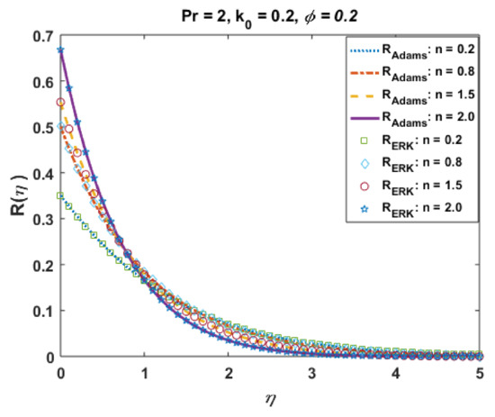
Figure 19.
Effects of n on .
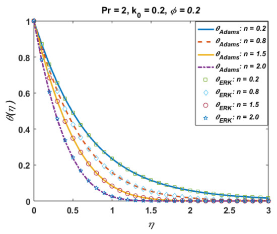
Figure 20.
Effects of n on .
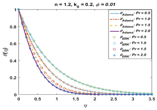
Figure 21.
Effects of Pr on .
We further analyzed the comparative study of different numerical methods, including Adam method, backward difference method (BDF), explicit Runge–Kutta (ERK), implicit Runge–Kutta (IRK) and extrapolation (ET) for CuO and Al2O3.based metallic nano polymeric suspension in the KKL fluidic model. Results for Adam, BDF, ERK, IRK and ET both types of suspension are presented in Table 5 in terms of computational time consumed, number of steps, ODE evaluations and different accuracy goals. Time and space accuracy for proposed numerical approaches were validated through numerical data provided in Table 5. Furthermore, one may see that accuracy convergence, stability of all numerical approaches was validated for all four different levels of accuracy goals, i.e., 10−7, 10−15, 10−22 and 10−30. However, the complexity of all algorithms increased for more stiff levels of accuracy goals. The performance of computational time complexity, as well as numbers of evaluation, were generally found best for Adam numerical method in the case of CuO and Al2O3.based metallic nano polymeric suspension in the KKL fluidic model for a scenario based on k0 = 0.6. The results were omitted for other scenarios due to similar trends inferences of accuracy, convergence, stability and complexity for all other cases of the KKL fluidic model.
Table 5.
Convergence and complexity test for .
5. Conclusions
In this communication, a novel flux model is incorporated to demonstrate the effects of nanofluidics and an enhancement of heat transfer in micropolar fluids suspension. Numerical simulations were performed using the KKL model for effective viscosity and thermal conductivity and hear-thinning/thickening performances under the influence of microrotations. The key observations of this investigation include the decay of velocity and temperature profile for positive values of k0, whereas profile R elucidates the jump effect near the surface. The ratio of momentum diffusivity to thermal diffusivity showed an inverse relation with the temperature profile. Error analysis is presented for different parameters, and it is noted that the error in computations was negligible. Moreover, the comparison of solutions computed via the Adams predictor–corrector method and explicit Runge–Kutta (RK) method have a reasonable agreement with each other. From the plotted graphs, it is noted that the results of CuO suspension are qualitatively similar to those of Al2O3.
In the future, one may implement intelligent computing solvers [38,39,40,41,42] for heat transfer in nanopolymeric suspension (CuO and Al2O3) using novel flux models as well as other nonlinear stiff fluidic systems [43,44,45,46,47]. Moreover, the presented study can be utilized in the future with the availability of real-time data for computational fluid dynamics problems.
Author Contributions
Conceptualisation, M.A. and S.E.A.; Methodology, M.A. and M.N.; Software, M.A. and M.A.Z.R.; Validation, M.Y.M. and Y.H.; Formal Analysis, M.A. and S.E.A.; Invetigation, M.N. and W.U.K.; Resources, M.A., W.U.K. and Y.H.; Date Curation, M.A. and M.N.; Writing Original Draft, M.A. and M.N.; Review and Editing, M.A. and M.N.; Visualisation, M.A. and M.N.; Supervision, M.Y.M. and Y.H.; Project adm., M.Y.M. and Y.H.; Funding, W.U.K. and Y.H. All authors have read and agreed to the published version of the manuscript.
Funding
This work was supported by the National Natural Science Foundation of China under Grant No. 51977153, 51977161, 51577046, State Key Program of National Natural Science Foundation of China under Grant No. 51637004, National Key Research and Development Plan (China) “important scientific instruments and equipment development” Grant No. 2016YFF010220, an Equipment research project in advance (China) Grant No. 41402040301.
Institutional Review Board Statement
Not applicable.
Informed Consent Statement
Not applicable.
Acknowledgments
All authors thank the editor and referees for their constructive comments regarding improvement of this work. M.Y. Malik extends his appreciation to the Deans of Scientific Research at King Khalid University, Abha, 61413, Saudi Arabia for their support through GRP–18/42.
Conflicts of Interest
The authors declare no conflict of interest.
References
- Eringen, A.C. Theory of micropolar fluids. J. Math. Mech. 1966, 16, 1–18. [Google Scholar] [CrossRef]
- Mehmood, A.; Afsar, K.; Zameer, A.; Awan, S.E.; Raja, M.A.Z. Integrated intelligent computing paradigm for the dynamics of micropolar fluid flow with heat transfer in a permeable walled channel. Appl. Soft Comput. 2019, 79, 139–162. [Google Scholar] [CrossRef]
- Souayeh, B.; Alfannakh, H. Radiative melting heat transfer through a micropolar nanoliquid by using Koo and Kleinstreuer model. Eur. Phys. J. Plus 2021, 136, 1–15. [Google Scholar] [CrossRef]
- Baharifard, F.; Parand, K.; Rashidi, M.M. Novel solution for heat and mass transfer of a MHD micropolar fluid flow on a moving plate with suction and injection. Eng. Comput. 2020, 1–18. [Google Scholar] [CrossRef]
- Yasmin, A.; Ali, K.; Ashraf, M. Study of heat and mass transfer in MHD flow of micropolar fluid over a curved stretching sheet. Sci. Rep. 2020, 10, 1–11. [Google Scholar] [CrossRef] [PubMed]
- Kumar, K.A.; Sugunamma, V.; Sandeep, N. Influence of viscous dissipation on MHD flow of micropolar fluid over a slendering stretching surface with modified heat flux model. J. Therm. Anal. Calorim. 2020, 139, 3661–3674. [Google Scholar] [CrossRef]
- Lund, L.A.; Omar, Z.; Khan, I.; Raza, J.; Sherif, E.-S.M.; Seikh, A.H. Magnetohydrodynamic (MHD) flow of micropolar fluid with effects of viscous dissipation and Joule heating over an exponential shrinking sheet: Triple solutions and stability analysis. Symmetry 2020, 12, 142. [Google Scholar] [CrossRef]
- Ghadikolaei, S.; Hosseinzadeh, K.; Ganji, D. Numerical study on magnetohydrodynic CNTs-water nanofluids as a micropolar dusty fluid influenced by non-linear thermal radiation and joule heating effect. Powder Technol. 2018, 340, 389–399. [Google Scholar] [CrossRef]
- Singh, K.; Pandey, A.K.; Kumar, M. Slip flow of micropolar fluid through a permeable wedge due to the effects of chemical reaction and heat source/sink with Hall and ion-slip currents: An analytic approach. Propuls. Power Res. 2020, 9, 289–303. [Google Scholar] [CrossRef]
- Rana, S.; Nawaz, M.; Saleem, S.; Alharbi, S.O. Numerical study on enhancement of heat transfer in hybrid nano-micropolar fluid. Phys. Scr. 2019, 95, 045201. [Google Scholar] [CrossRef]
- Ali, L.; Liu, X.; Ali, B.; Mujeed, S.; Abdal, S.; Khan, S.A. Analysis of magnetic properties of nano-particles due to a magnetic dipole in micropolar fluid flow over a stretching sheet. Coatings 2020, 10, 170. [Google Scholar] [CrossRef]
- Usman, A.H.; Shah, Z.; Humphries, U.W.; Kumam, P.; Thounthong, P. Soret, Dufour, and activation energy effects on double diffusive convective couple stress micropolar nanofluid flow in a Hall MHD generator system. AIP Adv. 2020, 10, 075010. [Google Scholar] [CrossRef]
- Tiwari, A.; Shah, P.D.; Chauhan, S.S. Analytical study of micropolar fluid flow through porous layered microvessels with heat transfer approach. Eur. Phys. J. Plus 2020, 135, 209. [Google Scholar] [CrossRef]
- Bhat, A.; Katagi, N.N. Micropolar fluid flow between a non-porous disk and a porous disk with slip: Keller-box solution. Ain Shams Eng. J. 2020, 11, 149–159. [Google Scholar] [CrossRef]
- Péters, F.; Lobry, L.; Lemaire, E. Pressure-driven flow of a micro-polar fluid: Measurement of the velocity profile. J. Rheol. 2010, 54, 311–325. [Google Scholar] [CrossRef]
- Sui, J.; Zheng, L.; Zhang, X.; Chen, G. Mixed convection heat transfer in power law fluids over a moving conveyor along an inclined plate. Int. J. Heat Mass Transf. 2015, 85, 1023–1033. [Google Scholar] [CrossRef]
- Zheng, L.; Zhang, X.; He, J. Transfer behavior of a class of generalized N-diffusion equations in a semi-infinite medium. Int. J. Therm. Sci. 2003, 42, 687–690. [Google Scholar] [CrossRef]
- Kandelousi, M.S. KKL correlation for simulation of nanofluid flow and heat transfer in a permeable channel. Phys. Lett. A 2014, 378, 3331–3339. [Google Scholar] [CrossRef]
- Haq, R.U.; Usman, M.; Algehyne, E.A. Natural convection of CuO–water nanofluid filled in a partially heated corrugated cavity: KKL model approach. Commun. Theor. Phys. 2020, 72, 085003. [Google Scholar] [CrossRef]
- AlSagri, A.S.; Moradi, R. Application of KKL model in studying of nanofluid heat transfer between two rotary tubes. Case Stud. Therm. Eng. 2019, 14, 100478. [Google Scholar] [CrossRef]
- Rana, S.; Nawaz, M. Investigation of enhancement of heat transfer in Sutterby nanofluid using Koo–Kleinstreuer and Li (KKL) correlations and Cattaneo–Christov heat flux model. Phys. Scr. 2019, 94, 115213. [Google Scholar] [CrossRef]
- Pourmehran, O.; Rahimi-Gorji, M.; Hatami, M.; Sahebi, S.; Domairry, G. Numerical optimization of microchannel heat sink (MCHS) performance cooled by KKL based nanofluids in saturated porous medium. J. Taiwan Inst. Chem. Eng. 2015, 55, 49–68. [Google Scholar] [CrossRef]
- Vijaybabu, T. Influence of permeable circular body and CuO–H2O nanofluid on buoyancy-driven flow and entropy generation. Int. J. Mech. Sci. 2020, 166, 105240. [Google Scholar] [CrossRef]
- Haq, R.U.; Aman, S. Water functionalized CuO nanoparticles filled in a partially heated trapezoidal cavity with inner heated obstacle: FEM approach. Int. J. Heat Mass Transf. 2019, 128, 401–417. [Google Scholar] [CrossRef]
- Rana, P.; Shukla, N.; Gupta, Y.; Pop, I. Analytical prediction of multiple solutions for MHD Jeffery–Hamel flow and heat transfer utilizing KKL nanofluid model. Phys. Lett. A 2019, 383, 176–185. [Google Scholar] [CrossRef]
- Sheikholeslami, M.; Mahian, O. Enhancement of PCM solidification using inorganic nanoparticles and an external magnetic field with application in energy storage systems. J. Clean. Prod. 2019, 215, 963–977. [Google Scholar] [CrossRef]
- Mehmood, K.; Hussain, S.; Sagheer, M. Numerical simulation of MHD mixed convection in alumina–water nanofluid filled square porous cavity using KKL model: Effects of non-linear thermal radiation and inclined magnetic field. J. Mol. Liq. 2017, 238, 485–498. [Google Scholar] [CrossRef]
- Li, Z.; Shehzad, S.; Sheikholeslami, M. An application of CVFEM for nanofluid heat transfer intensification in a porous sinusoidal cavity considering thermal non-equilibrium model. Comput. Methods Appl. Mech. Eng. 2018, 339, 663–680. [Google Scholar] [CrossRef]
- Gowda, R.J.P.; Munadel, S.A.; Kumar, R.N.; Prasannakumara, B.C.; Issakhov, A.; Gorji, M.R.; Turki, Y.A.A. Computational modelling of nanofluid flow over a curved stretching sheet using Koo–Kleinstreuer and Li (KKL) correlation and modified Fourier heat flux model. Chaos Solitons Fractals 2021, 145, 110774. [Google Scholar] [CrossRef]
- Sheikholeslami, M. Solidification of NEPCM under the effect of magnetic field in a porous thermal energy storage enclosure using CuO nanoparticles. J. Mol. Liq. 2018, 263, 303–315. [Google Scholar] [CrossRef]
- Awan, S.E.; Khan, Z.A.; Awais, M.; Rehman, S.U.; Raja, M.A.Z. Numerical treatment for hydro-magnetic unsteady channel flow of nanofluid with heat transfer. Results Phys. 2018, 9, 1543–1554. [Google Scholar] [CrossRef]
- Awan, S.E.; Awais, M.; Qayyum, A.; Rehman, S.U.; Khan, A.; Ali, H.; Raja, M.A.Z. Numerical computing paradigms for the dynamics of squeezing rheology of third grade fluid. Therm. Sci. 2020, 24, 4173–4182. [Google Scholar] [CrossRef]
- Awais, M.; Aqsa; Malik, M.; Awan, S.E. Generalized magnetic effects in a Sakiadis flow of polymeric nano-liquids: Analytic and numerical solutions. J. Mol. Liq. 2017, 241, 570–576. [Google Scholar] [CrossRef]
- Awan, S.E.; Raja, M.A.Z.; Mehmood, A.; Niazi, S.A.; Siddiqa, S. Numerical Treatments to Analyze the Nonlinear Radiative Heat Transfer in MHD Nanofluid Flow with Solar Energy. Arab. J. Sci. Eng. 2020, 45, 4975–4994. [Google Scholar] [CrossRef]
- Awan, S.E.; Raja, M.A.Z.; Gul, F.; Khan, Z.A.; Mehmood, A.; Shoaib, M. Numerical Computing Paradigm for Investigation of Micropolar Nanofluid Flow Between Parallel Plates System with Impact of Electrical MHD and Hall Current. Arab. J. Sci. Eng. 2021, 46, 645–662. [Google Scholar] [CrossRef]
- Awais, M.; Awan, S.E.; Raja, M.A.Z.; Parveen, N.; Khan, W.U.; Malik, M.Y.; He, Y. Effects of Variable Transport Properties on Heat and Mass Transfer in MHD Bioconvective Nanofluid Rheology with Gyrotactic Microorganisms: Numerical Approach. Coatings 2021, 11, 231. [Google Scholar] [CrossRef]
- Radhika, M.; Mahanthesh, B.; Thriveni, K. Solar radiative heat-driven Sakiadis flow of a dusty nanoliquid with Brownian motion and an exponential space-based heat source: Koo–Kleinstreuer–Li (KKL) model. Heat Transfer 2021, 50, 1232–1251. [Google Scholar] [CrossRef]
- Khan, J.A.; Raja, M.A.Z.; Syam, M.I.; Tanoli, S.A.K.; Awan, S.E. Design and application of nature inspired computing approach for nonlinear stiff oscillatory problems. Neural Comput. Appl. 2015, 26, 1763–1780. [Google Scholar] [CrossRef]
- Cheema, T.N.; Raja, M.A.Z.; Ahmad, I.; Naz, S.; Ilyas, H.; Shoaib, M. Intelligent computing with Levenberg–Marquardt artificial neural networks for nonlinear system of COVID-19 epidemic model for future generation disease control. Eur. Phys. J. Plus 2020, 135, 1–35. [Google Scholar]
- Parveen, N.; Awais, M.; Mumraz, S.; Ali, A.; Malik, M.Y. An estimation of pressure rise and heat transfer rate for hybrid nanofluid with endoscopic effects and induced magnetic field: Computational intelligence application. Eur. Phys. J. Plus 2020, 135, 1–41. [Google Scholar] [CrossRef]
- Ilyas, H.; Ahmad, I.; Raja, M.A.Z.; Tahir, M.B.; Shoaib, M. Intelligent computing for the dynamics of fluidic system of electrically conducting Ag/Cu nanoparticles with mixed convection for hydrogen possessions. Int. J. Hydrogen Energy 2021, 46, 4947–4980. [Google Scholar] [CrossRef]
- Sabir, Z.; Raja, M.A.Z.; Arbi, A.; Altamirano, G.C.; Cao, J. Neuro-swarms intelligent computing using Gudermannian kernel for solving a class of second order Lane-Emden singular nonlinear model. AIMS Math. 2021, 6, 2468–2485. [Google Scholar] [CrossRef]
- Awais, M.; Awan, S.E.; Iqbal, K.; Khan, Z.A.; Raja, M.A.Z. Hydromagnetic mixed convective flow over a wall with variable thickness and Cattaneo-Christov heat flux model: OHAM analysis. Results Phys. 2018, 8, 621–627. [Google Scholar] [CrossRef]
- Awais, M.; Awan, S.E.; Raja, M.A.Z.; Shoaib, M. Effects of Gyro-Tactic Organisms in Bio-convective Nano-material with Heat Immersion, Stratification, and Viscous Dissipation. Arab. J. Sci. Eng. 2020, 1–14. [Google Scholar] [CrossRef]
- Siddiqa, S.; Naqvi, S.; Begum, N.; Awan, S.; Hossain, M. Thermal radiation therapy of biomagnetic fluid flow in the presence of localized magnetic field. Int. J. Therm. Sci. 2018, 132, 457–465. [Google Scholar] [CrossRef]
- Awan, S.E.; Awais, M.; Rehman, S.U.; Niazi, S.A.; Raja, M.A.Z. Dynamical analysis for nanofluid slip rheology with thermal radiation, heat generation/absorption and convective wall properties. AIP Adv. 2018, 8, 075122. [Google Scholar] [CrossRef]
- Awais, M.; Raja, M.A.Z.; Awan, S.E.; Shoaib, M.; Ali, H.M. Heat and mass transfer phenomenon for the dynamics of Casson fluid through porous medium over shrinking wall subject to Lorentz force and heat source/sink. Alex. Eng. J. 2021, 60, 1355–1363. [Google Scholar] [CrossRef]
Publisher’s Note: MDPI stays neutral with regard to jurisdictional claims in published maps and institutional affiliations. |
© 2021 by the authors. Licensee MDPI, Basel, Switzerland. This article is an open access article distributed under the terms and conditions of the Creative Commons Attribution (CC BY) license (https://creativecommons.org/licenses/by/4.0/).