Article

Control of the Pore Structure of Plasma-Sprayed Thermal Barrier Coatings through the Addition of Unmelted Porous YSZ Particles

1
Key Laboratory of Pressure System and Safety, Ministry of Education, East China University of Science and Technology, Shanghai 200237, China
2
Department of Wing Surface, AECC Commercial Aircraft Engine Co. Ltd., Shanghai 200241, China
3
Marine Engineering College, Jimei University, Xiamen 361023, China
4
School of Mechanical and Electrical Engineering, Soochow University, Suzhou 215006, China
*
Author to whom correspondence should be addressed.
These authors contributed equally to this paper.
Coatings 2021, 11(3), 360; https://doi.org/10.3390/coatings11030360
Submission received: 5 March 2021 / Revised: 16 March 2021 / Accepted: 19 March 2021 / Published: 21 March 2021
(This article belongs to the Special Issue Plasma Sprayed Coatings)

Abstract

:
In this study, a new pore structure control method for plasma-sprayed thermal barrier coatings (TBCs) through the addition of unmelted, porous yttria-stabilized zirconia (YSZ) particles was investigated. Through a unique way of feeding powder, two powder feeders were used simultaneously at different positions of the plasma flame to deposit a composite structure coating in which a conventional plasma-sprayed coating was used as a matrix and unmelted micro-agglomerated YSZ particles were dispersed in the dense conventional coating matrix as second-phase particles. The effects of the distribution and content of second-phase particles on the microstructure, mechanical properties, and lifetime were explored in a furnace cyclic test (24 h) of the composite coating. The mechanical properties and lifetime of the composite coating depend on the content and morphology of the particles embedded in the coating. The lifetime of the composite structure coatings is significantly higher than that of the conventional coatings. By adjusting the spraying parameters, the lifetime of the composite coating prepared under the optimum process is up to 145 days, which is about three times that of the conventional coating. The results of this study provide guidance for the preparation of high-performance composite structure TBCs.

1. Introduction

Thermal barrier coatings (TBCs) are commonly used to protect hot sections of gas turbine engines. The operating temperature of turbine blades is highly increased because of the thermal insulation offered by TBCs, thereby improving the engine efficiency and performance [1,2,3,4]. For the further development of aviation turbine and industrial gas turbines, an improvement in their efficiency and specific power is required. In terms of TBCs applied to hot sections of gas turbine engines, thermal insulation performance and durability are two important indicators [5]. The thermal insulation performance and service life of the coating are largely determined by the microstructure of the TBCs [6,7,8]. Coatings fabricated with different spraying parameters have different long-term evolutions of their microstructure [9,10,11]. Therefore, TBCs can be further developed to meet the future needs of the gas turbine industry by adjusting their microstructure to improve the properties of the coating.
Plasma-sprayed coatings are formed by the successive accumulation of solidified lamellae, which exhibit a layered structure because the interface of the lamellae is not fully bonded and there are a large number of two-dimensional inter-splat pores between the lamellae [12,13,14,15,16,17]. The existence of interlaminar pores and other voids plays a leading role in the thermal and mechanical properties of the coating, resulting in the low thermal conductivity and high strain tolerance of TBCs [2,12,18,19,20]. A high strain tolerance helps to alleviate the thermal mismatch between a ceramic coating and metal substrate, thus, reducing the crack driving force of the coating during thermal shock [2,21,22,23,24,25,26]. Previous studies have shown that the microstructure of air plasma spraying (APS) coating can be adjusted by controlling the spraying parameters. However, the improvement of the comprehensive properties of plasma-sprayed TBCs is limited in the conventional controlling method [2,27,28,29]. Therefore, it is necessary to propose a new pore structure control strategy to adjust the microstructure to extend the durability of the coating and improve the overall performance of the coating.
A new strategy for the microstructure control of APS coatings leading to enhanced sintering resistance and prolonged durability was proposed in recent studies. Since the newly-structured thermal barrier coating (TBC) is obtained by embedding micro-agglomerated YSZ particles into coatings, the controlled-structure TBC is referred to as an embedded micro-agglomerated particle thermal barrier coating (EMAP TBC). [30,31]. Unlike traditional plasma-sprayed coatings, the EMAP TBC is formed by embedding unmelted or slightly melted micro-agglomerated particles into a traditional coating. This kind of embedding unmelted or slightly melted micro-agglomerated particles are made of 6~8% yttria stabilized zirconia (8YSZ). The structural advantage of EMAP TBC is that the coating matrix prepared by the traditional process ensures a high fracture toughness, and the dispersed micro-agglomerated particles significantly reduce the stiffness of the coating. In addition, the micro-agglomerated particles embedded in the coating have a strong sintering resistance because of their unique pore structure [30]. Two key points in the preparation of this new structure are notable. One is the use of two powder feeders simultaneously. During plasma spraying, a second-phase powder with a specific morphology is fed into a plasma jet at the end of the flame tail. A composite coating with a dense conventional coating as the matrix and unmelted second-phase powder dispersed evenly throughout the coating matrix is formed during the deposition process. The microstructure of the EMAP TBC can be adjusted by embedding the second-phase particles in a controlled way [30]. The other pivotal point related to developing this coating is the utilization of 1–5 µm 8YSZ particles agglomerated into spherical micro-agglomerated particles of 15–45 µm in size through spray granulation, as shown in Figure 1. After agglomeration, no high-temperature sintering or only slight sintering was conducted to maintain the porous characteristics.
The novel structure control strategy for plasma-sprayed YSZ coatings mentioned above is an inspiring solution to the challenges of enhancing coating sintering and durability. Meanwhile, several major process parameters can affect the structure of the EMAP TBC and, thus, the performance of the coating. In order to stabilize the preparation technology of the new coating and obtain a coating with an appropriate structure, it is necessary to know the influence of the preparation parameters of the new coating on the structure of the coating. In this study, several spraying parameters controlled in different directions will be proposed. EMAP TBCs with different microstructures were obtained by spraying processing control. Moreover, the relationship between the spraying parameters and pore structure, anti-sintering performance, and microhardness of coatings was established by microstructure analysis and a mechanical property test to verify the degree of influence of different spraying parameters. According to the control direction of the distance of embedded particles and the performance of sintering resistance according to the determined spraying parameters. The startup and shutdown of gas turbine engines requires a high thermal cycle/shock resistance under high thermal-mechanical load conditions.
As an important protective layer for gas turbine engines, thermal barrier coatings need to withstand thermal shock and thermal cycling under the same conditions. Therefore, it is necessary to conduct thermal cycle/thermal shock tests on newly developed thermal barrier coatings to evaluate the durability of the coatings. For many years, researchers have used various methods of simulating engine operating conditions to test the durability of thermal barrier coatings, such as furnace cyclic test (FCT), burner rig thermal shock tests (BRTSs), and jet engine thermal shock tests (JETSs) [32,33,34,35]. In the FCTmethod, the coating and substrate experience the same temperature during the FCT process, which is mainly used to study the failure mechanism caused by the thermal stress generated at the interface between the bond coat/Thermal grown oxides (TGO)/top coat [36]. In this study, the key point of the EMAP TBC to improve the durability of the coating is to relieve the thermal stress in the ceramic layer and the bonding layer/ceramic layer interface. Therefore, the FTC was used in this experiment to test the performance of the conventional TBC and EMAP TBC. Two groups of parameters were set to prepare the coating for the thermal cycle test in order to verify the accuracy of the control direction.

2. Materials and Methods

2.1. Preparation of Coatings

The coatings investigated in this study were deposited by atmospheric plasma spraying using a F4 plasmatron (F4, Sulzer Metco Co., Ltd., Winterthur, Zurich, Switzerland). Air plasma spraying (APS, Sulzer Metco Co., Ltd., Winterthur, Zurich, Switzerland) was used to spray 8YSZ powder. on a nickel-based superalloy (GH-5188) disk with a thickness of 6 mm and a diameter of 25.4 mm. Before the coating was deposited, the substrate surface was sandblasted to obtain a rough surface. Grit-blasting was performed using the 1212 type pressure sandblasting machine (Shanghai Liangshi painting equipment Co., Ltd., Shanghai, China). The working pressure was 0.7 MPa, and the corundum grit was of 60–80 mesh. The IFM G4 surface 3D topography instrument (manufacturer, city, state, country) was used to measure the surface roughness after grit-blasting. The Ra value was 4.052 μm, as shown in Figure 2. Before the deposition of the YSZ coating, a commercially available NiCoCrAlTaY powder (Amdry 962, Sulzer Metco, Westbury, NY, America) was used to deposit the bond coat (BC). Agglomerated sintered 8YSZ powder with a particle size range of 15−45 μm was used to deposit the ceramic top coat. During spraying, argon was used as the main gas and hydrogen as the auxiliary gas. The main gas flow and the auxiliary gas were controlled at 30 and 8 slpm, respectively. Nitrogen was used as the powder feed gas. Two powder feeders were used in this experiment with flow rates of 2.0 and 4.0 slpm, respectively. The plasma power was maintained at approximately 38.4 (600 A/64 V) and 40.2 kW (600 A/67 V) to deposit the YSZ and the bond coat, respectively. The traverse speed of the spray gun was kept as 500 mm/s with a distance of 100 mm for YSZ deposition. The total thickness of the TBCs (including the bonding layer and ceramic layer) was about 450 μm, and the ceramic layer was about 300 μm. The traverse speed of the spray gun was kept at 500 mm/s, with a distance of 100 mm for YSZ deposition. In this experiment, three parallel samples with a total of 12 samples were prepared for each set of parameters.
As the schematic diagrams show in Figure 3, the conventional TBC preparation method uses only the first-phase powder feeder to prepare the coatings under the same spraying parameters. In the EMAP TBC, the influence of the spraying parameters on the microstructure of the coatings with new structures was studied using control variables. Based on the microstructure changes in the EMAP TBC samples prepared at 35 mm and 40 mm powder feeder distances, the influence the distance of the powder feeder has on the structure of the embedded particles was evaluated. Furthermore, when controlling the powder feeder distance, the influence of the powder feeding rate on the embedded particle structure was evaluated by changing the first-phase powder feeding rate and the second-phase powder feeding rate. For the convenience of the latter description, the conventional powder feeder and second-phase powder feeder were called powder feeder 1 and powder feeder 2. The position of powder feeder 1 was fixed, while adjusting the position of powder feeder 2 so that the distance between powder feeder 1 and powder feeder 2 was 35 and 40 mm, respectively. In that case, the second-phase powder was fed into the plasma jet at the end of the flame tail of different positions during the plasma splaying process. The melting states of the second-phase particles are likely diverse because of the different amounts of time they spend in the plasma jet. The degree of melting of embedded particles is estimated based on the content of embedded particles in the composite structure coating. Meanwhile, the variation in the distance between the two powder feeders also possibly diversifies the distribution of the second-phase embedded particles on the coating matrix. In addition, the content of embedded particles can, likewise, be adjusted by controlling the feeding rates. The spaying parameter combination of a 12 g/min feeding rate for powder feeder 1 and 16 g/min feeding rate for powder feeder 2 is set as the control group. The feeding rate of powder feeder 1 was increased to 16 g/min, which was expected to obtain different embedded particle contents and distributions. The plasma spraying parameters for depositing various TBCs are summarized in Table 1.

2.2. Sample Characterization

In order to determine the microstructure of the coating after the processing control, the samples were cut along the diameter with a precision cutting machine (Shanghai Qunhong Instrument Equipment Co., Ltd., Shanghai, China) to obtain a cross-section and the sample was ground and polished utilizing a standard metallographic procedure. Microstructural analysis was conducted on the polished cross-sections and fracture surfaces of the coatings using a scanning electron microscope in backscattered and secondary electron (SEM, ZEISS EVO MA15, Carl Zeiss SMT Ltd., Cambridge, UK) modes with an acceleration voltage of 15 kV. Image analysis is a convenient and reliable method to characterize the microstructure of thermal spray coatings [37]. By analyzing the typical image with a sufficiently high magnification, the structure and distribution of the pores inside the coating can be determined. The Vickers hardness of the cross-section was measured by a Vickers hardness tester (Shanghai Taiming Optical Instrument Co., Ltd., Shanghai, China). The hardness test was carried out under a load of 500 g and a holding time of 30 s. Ten measurements were taken on each coating sample to obtain a reliable hardness value.

2.3. Thermal Exposure Test for TBCs

With the isothermal heat treatment utilized, the sintering properties of the EMAP TBCs with different spraying parameters and conventional TBCs were studied. The thermal exposure of the coating was performed in a furnace (in air) for different durations of 1, 2, 5, 10, 20, 50, and 100 h at 1300 °C. After gradually holding for different periods of time, the sample was cooled down to room temperature.

2.4. Furnace Cyclic Test for TBCs

Generally, the temperature range in FCT is 1000–1200 °C, and the heating and cooling time depends on the materials and components used. In the case of a land-based gas turbine engine, a thermal cycle test with a longer holding time at a high temperature will be effective because the operating time at a high temperature is relatively long [38]. Therefore, the 24-h cycle test is mainly used, with heating for 23.5 h and cooling for 0.5 h [39,40]. In this study, FCT was performed in a box resistance furnace (Shanghai Shiyan Electric Furnace Co., Ltd., Shanghai, China) to evaluate the thermal durability of the coating samples at 1100 °C with a cycle of 23.5 h of high-temperature holding pressure and 0.5 h of natural cooling (room temperature). FCT was carried out using a laboratory muffle furnace (SX2-10-13, Shanghai Shiyan Furnace Co., Ltd., Shanghai, China), and the loading and unloading of the sample were carried out manually. After the cooling cycle, the top coat of each sample was checked. The failure criterion of the furnace cyclic test is if more than 20% of the top coat peels off and/or the interface between the top coat and the bond coat layer cracks [41]. Two parallel samples are set for each group of samples to ensure the reliability of the experimental data.

3. Results and Discussion

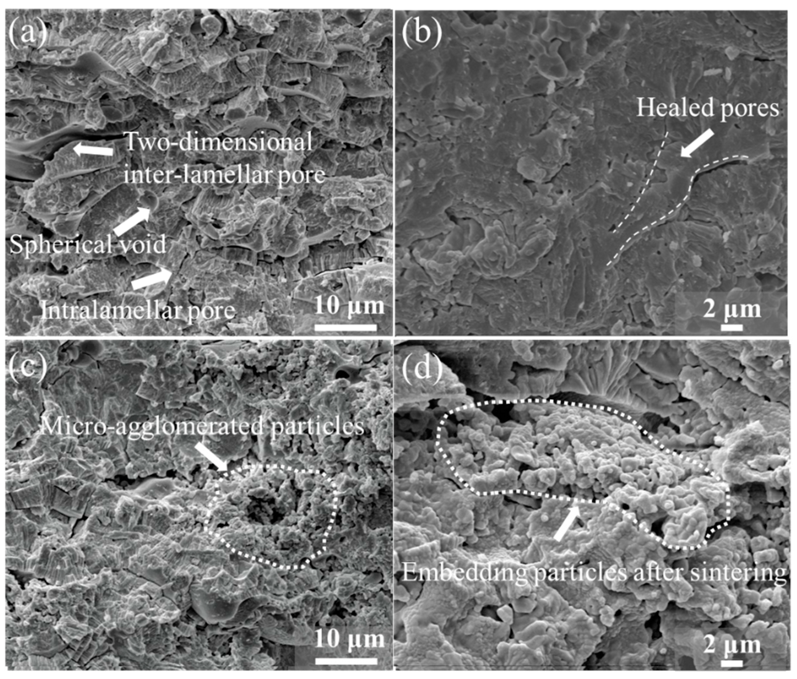
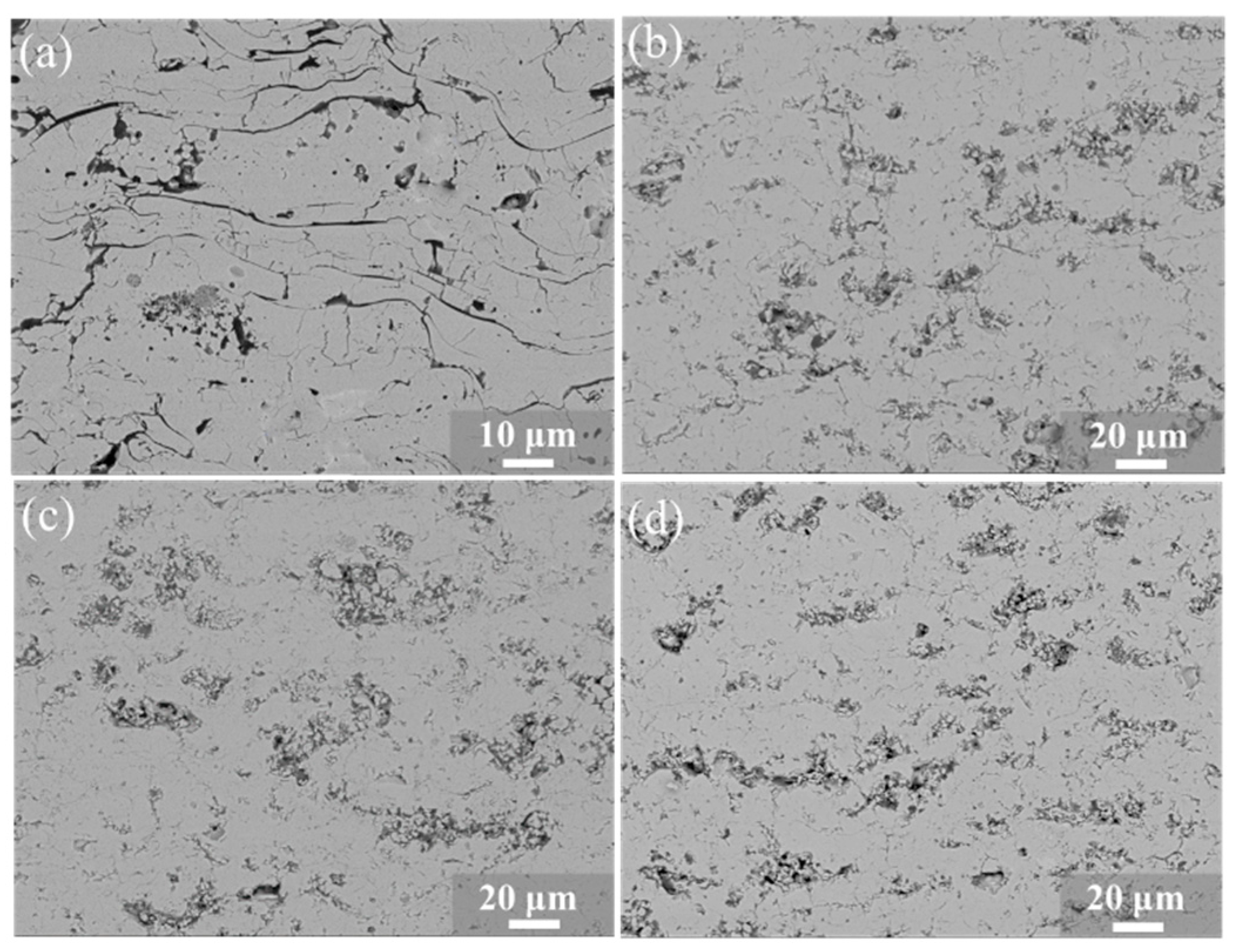
3.1. Microstructure of Coatings

As displayed in Figure 4, particles with different contents and distributions were embedded in the coating matrix. The coating forming mechanism of the EMAP TBC during the improved deposition process determines the distribution and amount of particles embedded. In the process of adjusting the spraying parameters, the embedded particles will exist in the coating matrix with different distributions and contents. The final existence state of the embedded particles in the matrix coating is an important factor for the improvement of the anti-sintering property and thermal shock lifetime of the new coating [30]. It can be seen from Figure 4a that there are few particles embedded in the EMAP TBC and their distribution is irregular, which offers little benefit to the sintering resistance and thermal cycling performance of the coating. There are too many embedded particles in the coating in Figure 4b, which can damage the fracture toughness of the EMAP TBC and even become a source of cracks during the thermal cycle. The structure in Figure 4c is ideal, and the embedded particles are uniformly and dispersedly distributed in the coating, which can increase the strain tolerance without reducing the fracture toughness of the EMAP TBC. Therefore, it is very important to study spraying parameters that have a greater influence on the content and distribution of the embedded particles.

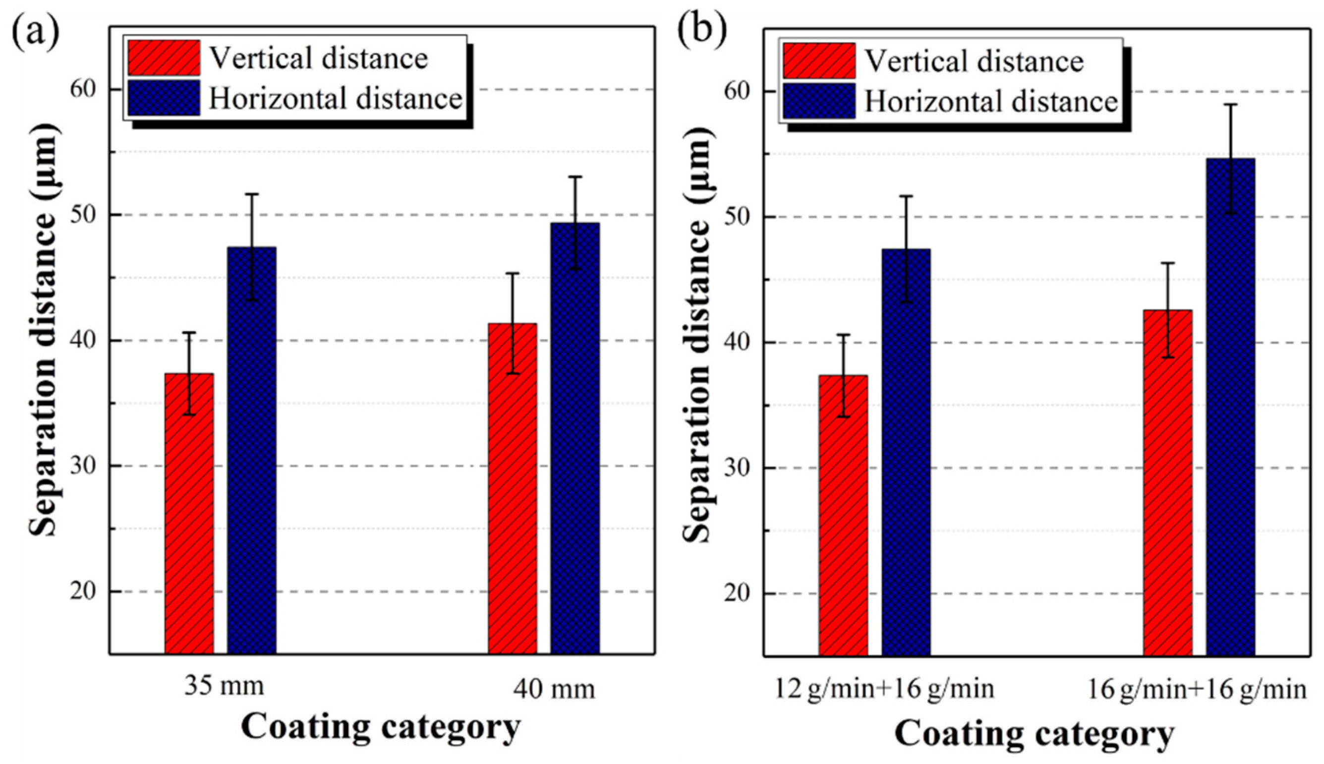
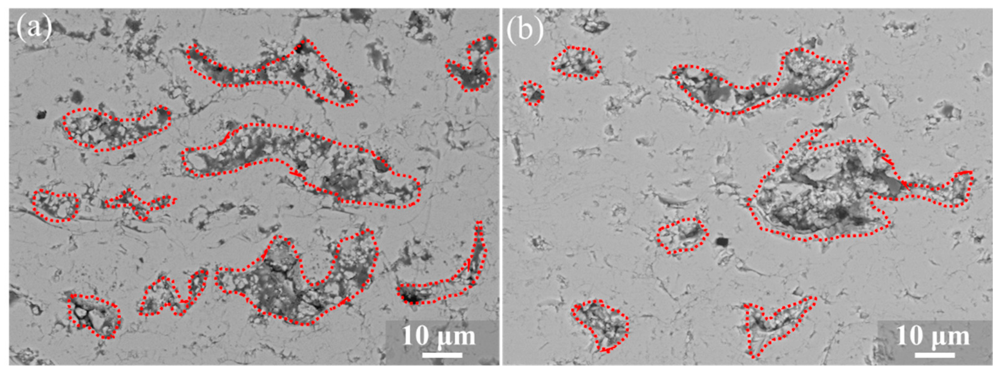
3.2. Distribution of Embedding Particles

In this study, vertical distance and horizontal distance were used to characterize the distribution of particles embedded in the coating matrix. The distance between the particles embedded in the EMAP TBC prepared at different powder feeder distances and different powder feeding rates was counted. One of several sets of samples was selected to describe the measurement processes, as shown in the schematic diagrams in Figure 5. First, the embedded particle area was selected. The Image J software (version 2.1.4.7) was used to find the centroid of the embedded particle area, and a cross is marked on it. Through the calculation of the total thickness of the coating and the translation times of the spray gun, it was concluded that the thickness of each spray was 20–25 μm. The loosely agglomerated particles were embedded in the layered structure with the deposition of the traditional coating. The embedded particles exist at the peaks or troughs of the layered structure composed of countless deformed particles interlaced and stacked in waves. As a consequence, an auxiliary line is drawn every 22.5 μm from the embedded particle center at the top of the image to facilitate subsequent measurements and unify the measurement criteria.
In order to unify the process of measurement, three measurement standards were stipulated for measuring the vertical distance, including: (a) the two embedded particles measured cannot be in a region consisting of two adjacent auxiliary lines, (b) the embedding particles measured are the two closest to each other, and (c) the embedding particles will be regarded as an independent measurement unit if they are exactly in the middle of the line. Two criteria for measuring the horizontal distance were formulated, including: (a) both embedded particles measured must be in a region consisting of two adjacent auxiliary lines, and (b) the embedding particles measured should be between the two adjacent auxiliary lines. In this study, the distances of the particles embedded in the EMAP TBCs with different powder feeder distances and different powder feeding rates were measured. Images of three different regions were selected for each coating sample to measure the coating prepared by the above experimental procedure. The horizontal and vertical distances of about 110 embedded particles were calculated for each sample.
Figure 6 shows the measurement results of the embedded particle distribution. The distributions of embedded particles in the EMAP TBC prepared with different spraying parameters are quite different. When the distance between powder feeder 1 and powder feeder 2 increased from 35 to 40 mm, the horizontal distance and vertical distance of the embedded particles varied slightly. The vertical distance and horizontal distance of EMAP TBC prepared with 35 mm were 37.4 and 47.4 µm, while they were 41.4 and 49.4 µm in the control group. The above results show that, when the distance of the powder feeder varies between 35 and 40 mm, it has a small impact on the distribution of the embedded particles. The embedded particles showed a different distribution in the coating matrix with different rates of powder feeding. When the feeding rate of powder feeder 1 increased from 12 to 16 g/min, the vertical distance of the embedded particles increased 13.94%, while the horizontal distance increased 15.1%. Notably, the vertical distance and horizontal distance are comparatively increased when the feeding rate of powder feeder 1 was turned up to 16 g/min. Therefore, controlling the speed of powder feeder 1 has a greater influence on the distribution of the embedded particles.

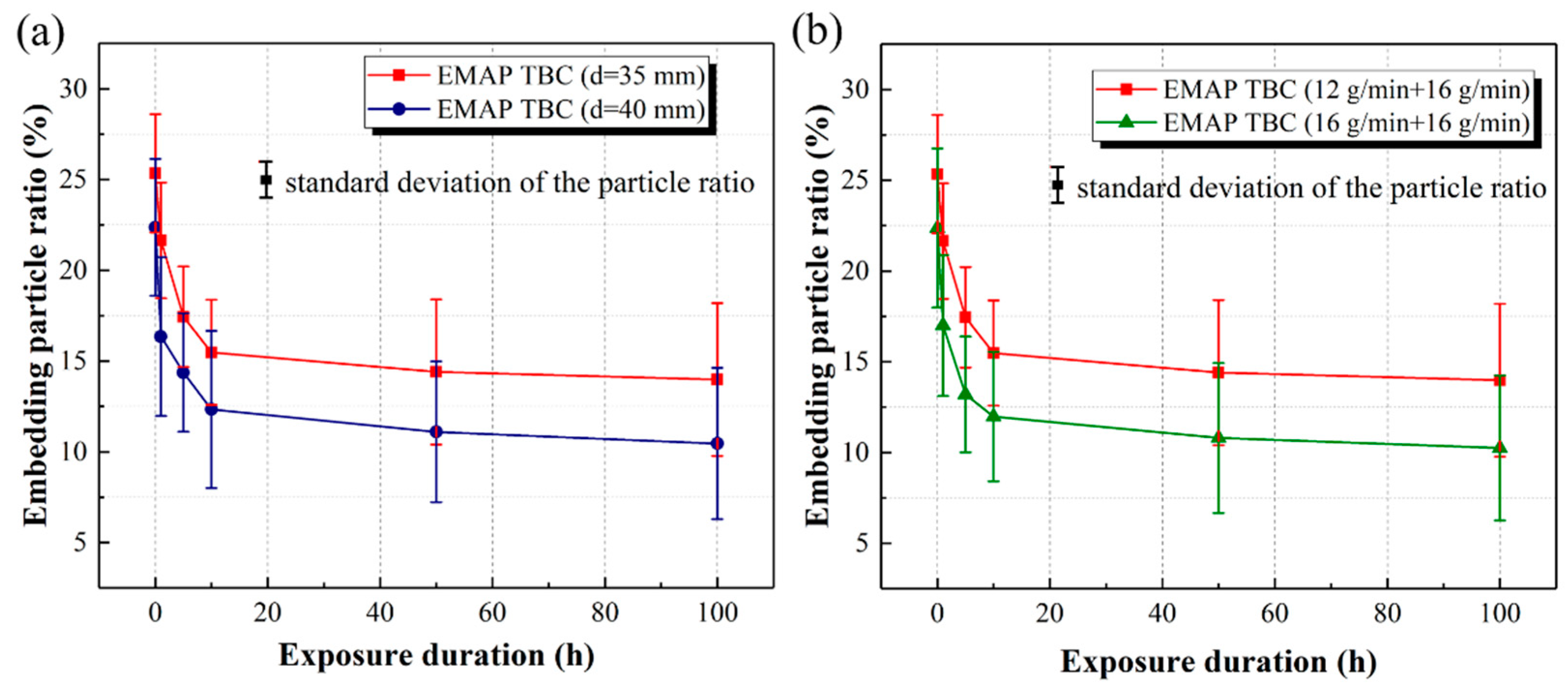
3.3. Sintering Resistance

Sintering is one of the main failure mechanisms of TBCs at elevated operation temperatures [42]. The sintering behavior of EMAP TBC and the conventional TBC was investigated in terms of the microstructure and pore structure evolution in this study. Figure 7 shows the fracture structure of the coating prepared by conventional and new processes and its morphology after sintering at 1300 °C for 40 h. As shown in Figure 7a, plasma-sprayed coatings mainly contain three types of pore: two-dimensional intra-lamellar pores, interlamellar pores, and spherical voids. The formation mechanism of pores is very complicated [43,44]. Two-dimensional intra-lamellar pores are formed on the boundary of lamellar particles, which are generally slender and tend to be sprayed vertically. Interlamellar pores are caused by thermal stress parallel to the substrate during cooling, generally parallel to the spray direction and across a single particle layer. Spherical voids are generally located inside lamellar particles. Both interlamellar pores and spherical voids are formed by gas interception in the process of plasma spraying. The plasma gas and entrained ambient gas will be partially dissolved in the molten droplets. The cooling rate of the coating is very fast, and the pores formed by the dissolved gas are not released in time, forming a circular structure [45,46]. Figure 7b shows that the conventional TBC becomes denser after 40 h of thermal exposure than the as-sprayed conventional TBC. In contrast, due to the existence of molten second-phase particles, the EMAP TBC remains loose and porous after sintering at 1300 °C for 40 h. It can be inferred that the sintering resistance of the EMAP TBC is remarkably improved by the pore structure tailoring. As mentioned earlier, the pore formation mechanism of the conventional TBC is complex and difficult to control, while the second-phase particles of the EMAP TBC can be easily embedded in the coating matrix. Combined with the previous research, it can be shown that the distribution and content of the embedded particles shown in Figure 7d can be controlled by changing the distance of the powder feeder and the rate of powder feeding.
The Adobe Photoshop CC 2019 software (version 20.0.0) was used to measure the the pore structure proportion of SEM images of coatings with a magnification of 1000 times. Embedding particles with wire frames were selected. The area mentioned above was marked by the Quick Select tool in the Adobe Photoshop CC 2019 software to obtain pixels in the region of the embedding particles, and then the percentage of embedding particles was calculated, as shown in Figure 8. The embedding particles are present in the coating matrix in an unmelted or slightly melted state. Therefore, some of the embedded particles will be melted as a conventional TBC after long-term high-temperature exposure. However, the distribution does not change significantly after sintering for 40 h, which is one of the advantages of this newly tailored structure. The rate at which the particles melt may depend on the melting state of the second-phase powder. The ratio of the area of embedding particles to the area of the whole image is called the embedding particle ratio, and is used to represent the change in the embedding particle content of the EMAP TBC during sintering. Consequently, the embedded particle ratio in the EMAP TBC prepared with different powder feeding distances and powder feeding rates shows a discrepant descending rate during high-temperature exposure over time, as shown in Figure 9. When the distances between powder feeder 1 and powder feeder 2 are 35 and 40 mm, the proportion of particles embedded in the latter is smaller than that in the former, without a significant difference in the sintering rate. Furthermore, the powder feeding rate has great influence on the content of embedded particles during sintering. Compared to the coatings fabricated with powder feeding rates of 12 g/min (powder feeder 1) and 16 g/min (powder feeder 2), the coating prepared by adjusting the feeding rate of powder feeder 1 up to 16 g/min showed a similar sintering rate but lower embedding particle ratio. This result shows that changing the powder feeding rate of powder feeder 1 has a small impact on the sintering rate of the EMAP TBC, but a great effect on the content of embedded particles.

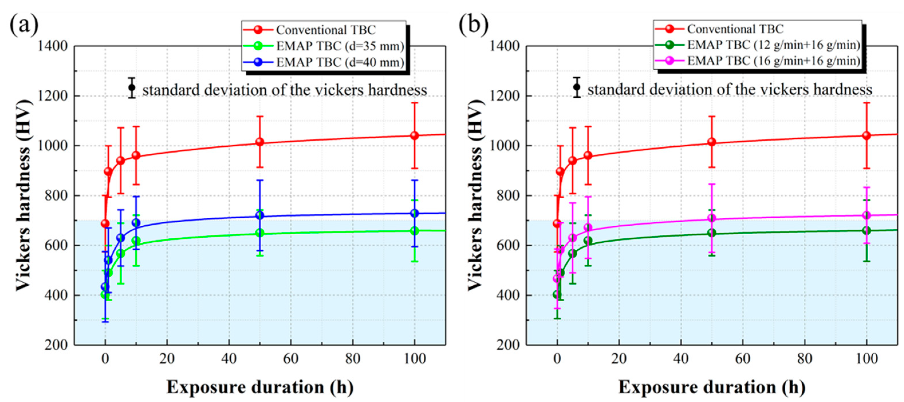
3.4. Mechanical Properties

The strain tolerance of TBC is significantly affected by the increase in stiffness caused by micro porous sintering [47,48]. Figure 10 shows the changes in the mechanical properties of the conventional TBC and the EMAP TBC prepared by different optimized processes with the increase in thermal exposure time at 1300 °C. Thanks to the presence of embedded porous particles, the micro-hardness of the EMAP TBC is significantly lower than that of the conventional TBC both in the as-sprayed state and after thermal exposure. When the distances between powder feeder 1 and powder feeder 2 are 35 and 40 mm, the rate of increase in the micro-hardness of the EMAP TBC is close, but the micro-hardness value of the latter is higher than that of the former as a whole. In addition, adjusting the powder feeding rate also has an effect on the sintering rate and micro-hardness value of the newly structured coating. Compared with the combination of 12 g/min (powder feeder 1) and 16 g/min (powder feeder 2) for the powder feeding rate, when the powder feeding rate of powder feeder 1 is increased to 16 g/min, the rate of increase and the value of the micro-hardness of the EMAP TBC increased slightly. Therefore, adjusting the feeding rate of powder feeder 1 has a small impact on the microhardness of the new structure coating during the sintering process.
During the sintering process, the evolution of the mechanical properties of the EMAP TBC are the same as the evolution of the second-phase particles embedded in the coating matrix. This shows that the existence of embedding particles does affect the sintering resistance of the coating. The distribution, content, and melting state of embedding particles have a certain influence on the sintering properties. In this case, the anti-sintering performance of the coating increased, the hardness of the new coating is the lowest, and the rate of increase in the hardness during the sintering is also lower. A large number of second phase powders were sent out at the same time, and some of the powders were slightly melted or unmelted. The overall sintering resistance of the new coating was improved. The result above shows that the second phase particles can be controllably embedded into the coating by adjusting the powder feeding rate, and the sintering resistance of the coating can also be controlled.

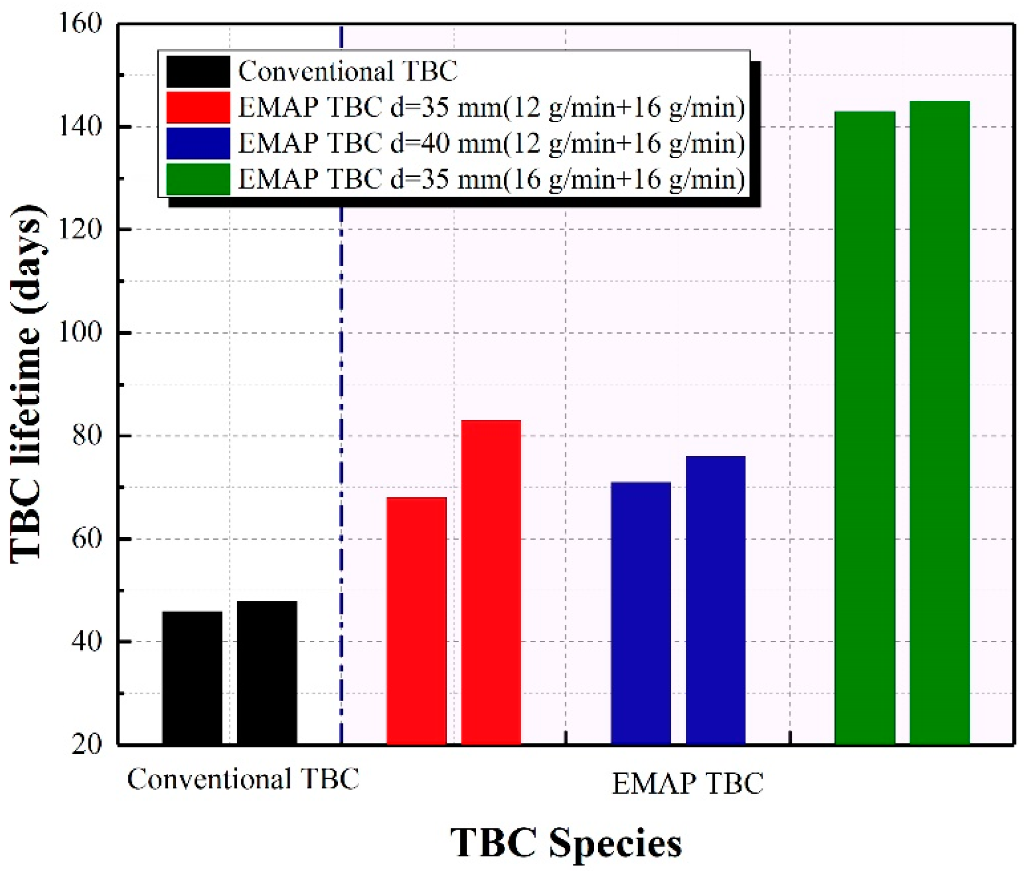
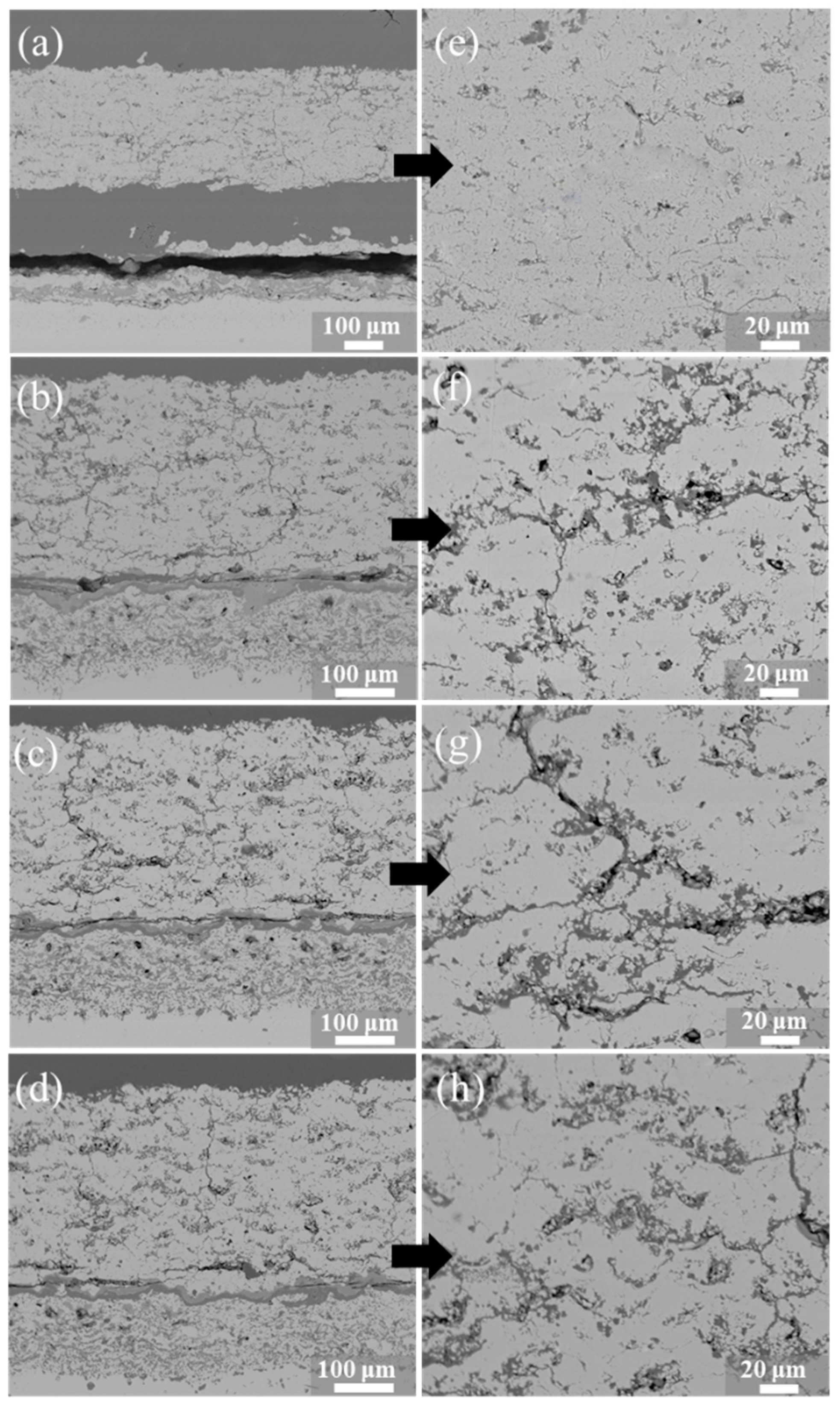
3.5. Lifetime and Failure Analysis in FCT

Durability is an important factor to evaluate the performance of thermal barrier coatings, and the reason why EB-PVD (electron beam physical vapor deposition)coating has a higher life than APS (air plasma spraying) coating is because the ceramic coating prepared by the former has higher strain resistance [33,49]. Due to the existence of embedded particles, the strain tolerance of the EMAP TBC is improved, and the conventional TBC substrate ensures its high fracture toughness, so its thermal cycle performance is expected to improve. The lifetimes of the conventional TBC and EMAP TBCs with cyclic conditions in FCT were assessed at 1100 °C and their lifetimes were compared, as shown in Figure 11. According to the test results, it can be seen that the new coating prepared when the distance between the two powder feeders was 35 and 40 mm had a similar lifetime and was almost twice as long as the conventional TBC, which was consistent with the previous research results on the distribution of embedded particles and anti-sintering properties. It was mentioned earlier that controlling the powder feeding rate of powder feeder 1 has great influence on the distribution and content of embedded particles. By controlling the variables, the powder feeding rate of powder feeder 1 was increased to 16 g/min, and the lifetime of the EMAP TBC obtained was not only higher than that of conventional TBC, but also twice as long as that of the EMAP TBC in the control group. Therefore, under the condition that the distance of the powder feeder is kept unchanged at 35 mm, the embedded particle content and distribution obtained by adjusting the powder feeding rate of powder feeder 1 and powder feeder 2 to 12 and 16 g/min, respectively, can give full control to the new composite structure.
Figure 12 shows the sprayed microstructure of coatings, and the conventional TBC shows a typical two-dimensional inter-lamellar pore structure. The distribution and content of embedded particles in the EMAP TBC prepared with 35 and 40 mm are similar, which also shows that the embedded particles in the EMAP TBC have a direct effect on the lifetime. After increasing the powder feeding rate of powder feeder 1 to 16 g/min, the distribution of embedded particles is more uniform and the content is moderate compared with that of the control group, which indicates that the lifetime of the new structural coating can be further improved by controlling the content and distribution of the embedded particles and t the EMAP TBC has great potential. The microstructure of the experiments after thermal cycling was analyzed. When the TBC sample is under the condition of thermal cycling, the conventional TBC peels off above a TGO after 48 cycles. Judging from the crack length of the coating, the cracking degree of the conventional TBC is much more serious than that of the EMAP TBCs, as shown in Figure 13. On the other hand, the crack length of the EMAP TBC prepared by powder feeder 1 and powder feeder 2 with a powder feeding rate of 16 g/min is still smaller than that of the control group after 145 cycles (3407.5 h heating time). From the local microstructure of the ceramic layer, the two-dimensional interlamellar pore structure of the conventional TBC was basically healed, while the second-phase particle structure of the EMAP TBCs still existed in the coating matrix. In this, all the samples have the same bonding layer and matrix, so the main factors affecting the lifetime of the TBC are the microstructure and mechanical properties of the ceramic surface.
In summary, the lifetime of the EMAP TBC was greatly improved due to the existence of embedded particles, and the lifetime was further improved after adjusting the spraying parameters, which lays a foundation for the further study of the EMAP TBC in the future.

4. Conclusions

In this study, the spraying parameters of advanced TBCs with a composite structure ceramic top coat were explored. Three crucial functional parameters of TBCs—sintering resistance, mechanical properties, and service lifewere studied, and the relationship between the process parameters, microstructure, and coating properties was established. The composite structural coatings consisting of a dense conventional coating matrix and dispersed porous particles were formed by introducing unmelted or slightly melted micron-agglomerated YSZ powders into the conventional coating deposition process from the tail of the plasma frame. The feeding position and feeding rate of the second-phase embedded powder are the most important process parameters affecting the structure and properties of the composite coating. The strain tolerance and sintering resistance of the coating can be improved with the increase in the number of embedded particles. Through the comparative study of different parameters, optimized process parameters were obtained for the preparation of a high-performance composite structural coating. The lifetime of the composite coating prepared under the optimum process is up to 145 days, which is about three times that of a conventional coating.

Author Contributions

Y.L., J.H., and W.W. conceived and designed the experiments. D.Y., H.F., and D.G. performed the experiments. S.T., X.G. and Z.Y. analyzed the data. All authors have read and agreed to the published version of the manuscript.

Funding

This research were funded by National Natural Science Foundation of China, No. 51775189, Shanghai Space Science and Technology Innovation Fund, SAST 2019056 and Science and Technology Project of Fujian Province 2019H6017, FJHJF-L-2020-6.

Data Availability Statement

Not applicable.

Conflicts of Interest

The authors declare no conflict of interest.

References

  1. Padture, N.P.; Gell, M.; Jordan, E.H. Thermal barrier coatings for gas-turbine engine applications. Science 2002, 296, 280–284. [Google Scholar] [CrossRef]
  2. Gupta, M.; Dwivedi, G.; Nylén, P.; Vackel, A.; Sampath, S. An Experimental Study of Microstructure-Property Relationships in Thermal Barrier Coatings. J. Therm. Spray Technol. 2013, 5, 659–670. [Google Scholar] [CrossRef]
  3. Clarke, D.R.; Oechsner, M.; Padture, N.P. Thermal-barrier coatings for more efficient gas-turbine engines. MRS Bull. 2012, 10, 891–898. [Google Scholar] [CrossRef] [Green Version]
  4. Gupta, M.; Curry, N.; Nylén, P. Design of next generation thermal barrier coatings—Experiments and modelling. Surf. Coat. Technol. 2013, 220, 20–26. [Google Scholar] [CrossRef]
  5. McPherson, R. The Relationship between the Mechanism of Formation, Microstructure and Properties of Plasma-Sprayed Coatings. Thin Solid Films. 1981, 3, 297–310. [Google Scholar] [CrossRef]
  6. Sampath, S. Thermal Sprayed Ceramic Coatings: Fundamental Issues and Application Considerations. Int. J. Mater. Prod. Technol. 2009, 3–4, 425–429. [Google Scholar] [CrossRef]
  7. Curry, N.; Markocsan, N.; Östergren, L.; Li, X.H.; Dorfman, M. Evaluation of the Lifetime and Thermal Conductivity of Dysprosia-Stabilized Thermal Barrier Coating Systems. J. Therm. Spray. Technol. 2013, 6, 672–864. [Google Scholar] [CrossRef]
  8. Huang, J.; Wang, W.; Lu, X.; Liu, S.; Li, C. Influence of lamellar interface morphology on cracking resistance of plasma-sprayed ysz coatings. Coatings 2018, 8, 187. [Google Scholar] [CrossRef] [Green Version]
  9. Basu, S.N.; Ye, G.; Gevelber, M.; Wroblewski, D. Microcrack Formation in Plasma Sprayed Thermal Barrier Coatings. Int. J. Refract. Met. Hard Mater. 2005, 23, 335–343. [Google Scholar] [CrossRef]
  10. Li, G.; Wang, L.; Yang, G. Achieving self-enhanced thermal barrier performance through a novel hybrid-layered coating design. Mater. Des. 2019, 167, 107647. [Google Scholar] [CrossRef]
  11. Mauer, G.; Vaßen, R.; Stöver, D. Atmospheric Plasma Spraying of Yttria-Stabilized Zirconia Coatings with Specific Porosity. Surf. Coat. Technol. 2009, 204, 172–179. [Google Scholar] [CrossRef]
  12. Mcpherson, R. A review of microstructure and properties of plasma sprayed ceramic coatings. Surf. Coat. Technol. 1989, 40, 173–181. [Google Scholar] [CrossRef]
  13. Li, C.; Wang, W. Quantitative characterization of lamellar microstructure of plasma-sprayed ceramic coatings through visualization of void distribution. Mater. Eng. A 2004, 386, 10–19. [Google Scholar] [CrossRef]
  14. Allen, A.; Ilavsky, J.; Long, G. Microstructural characterization of yttria-stabilized zirconia plasma-sprayed deposits using multiple small-angle neutron scattering. Acta Mater. 2001, 49, 1661–1675. [Google Scholar] [CrossRef] [Green Version]
  15. Antou, G.; Montavon, G.; Hlawka, F. Evaluation of modifications induced on pore network and structure of partially stabilized zirconia manufactured by hybrid plasma spray process. Surf. Coat. Technol. 2004, 180, 627–632. [Google Scholar] [CrossRef]
  16. Fauchais, P.; Vardelle, M.; Goutier, S. Latest researches advances of plasma spraying: From splat to coating formation. J. Therm. Spray. Technol. 2016, 25, 1534–1553. [Google Scholar] [CrossRef]
  17. Kulkarni, A.; Goland, A.; Herman, H. Microstructure-Property Correlations in Industrial Thermal Barrier Coatings. J. Am. Ceram. Soc. 2005, 87, 1294–1300. [Google Scholar] [CrossRef]
  18. Li, C.; Ohmori, A. Relationships between the Microstructure and Properties of Thermally Sprayed Deposits. J. Therm. Spray. Technol. 2002, 11, 365–374. [Google Scholar] [CrossRef]
  19. Sevostianov, I.; Kachanov, M. Elastic and Conductive Properties of Plasma-Sprayed Ceramic Coatings in Relation to Their Microstructure: An Overview. J. Therm. Spray. Technol. 2009, 18, 822–834. [Google Scholar] [CrossRef] [Green Version]
  20. Huang, J.; Wang, W.; Xiang, L. Effect of Particle Size on the Thermal Shock Resistance of Plasma-Sprayed YSZ Coatings. Coatings 2017, 7, 150. [Google Scholar] [CrossRef] [Green Version]
  21. Zou, Z.; Xing, C.; He, L.; Shan, X.; Luo, L.; Zhao, X.; Guo, F.; Xiao, P. A highly strain and damage tolerant thermal barrier coating fabricated by electro: Prayed zirconia hollow spheres. J. Am. Ceram. Soc. 2018, 101, 4375–4386. [Google Scholar] [CrossRef]
  22. Rezvani, R.; Farrahi, G.; Azadi, M. Stress analysis of thermal barrier coating system subjected to out-of-phase thermo-mechanical loadings considering roughness and porosity effect. Surf. Coat. Technol. 2015, 262, 77–86. [Google Scholar] [CrossRef]
  23. Emine, B.; Daniel, E.; Mack, G.; Mauer, R.; Mücke, R. Porosity-Property Relationships of Plasma-Sprayed Gd2Zr2O7/YSZ Thermal Barrier Coatings. J. Am. Ceram. Soc. 2015, 98, 2647–2654. [Google Scholar]
  24. Huang, J.; Wang, W.; Yu, J.; Wu, L.; Feng, Z. Effect of Particle Size on the Micro-cracking of Plasma-Sprayed YSZ Coatings during Thermal Cycle Testing. J. Therm. Spray. Technol. 2017, 26, 1–9. [Google Scholar] [CrossRef]
  25. Mauer, G.; Du, L.; Vaßen, R. Atmospheric Plasma Spraying of Single Phase Lanthanum Zirconate Thermal Barrier Coatings with Optimized Porosity. Coatings 2016, 6, 49. [Google Scholar] [CrossRef] [Green Version]
  26. Cheng, B.; Wei, Z.; Chen, L. Prolong the durability of La2Zr2O7/YSZ TBCs by decreasing the cracking driving force in ceramic coatings. J. Eur. Ceram. Soc. 2018, 38, 5482–5488. [Google Scholar] [CrossRef]
  27. Darolia, R. Thermal barrier coatings technology: Critical review, progress update, remaining challenges and prospects. Int. Mater. Rev. 2013, 58, 315–348. [Google Scholar] [CrossRef]
  28. Markocsan, N.; Gupta, M.; Joshi, S.; Nylén, P.; Li, X.H.; Wigren, J. Liquid feedstock plasma spraying: An emerging process for advanced thermal barrier coatings. Journal of Thermal Spray Technology. Therm. Spray Technol. 2017, 26, 1104–1114. [Google Scholar] [CrossRef] [Green Version]
  29. Viswanathan, V.; Dwivedi, G.; Sampath, S. Engineered Multilayer Thermal Barrier Coatings for Enhanced Durability and Functional Performance. J. Eur. Ceram. Soc. 2014, 9, 2770–2778. [Google Scholar] [CrossRef]
  30. Huang, J.; Wang, W.; Li, Y.; Fang, H.; Tu, S. A novel strategy to control the microstructure of plasma-sprayed ysz thermal barrier coatings. Surf. Coat. Technol. 2020, 402, 126304. [Google Scholar] [CrossRef]
  31. Huang, J.; Wang, W.; Li, Y.; Fang, H.; Ye, D.; Zhang, X.; Tu, S. Improve durability of plasma-splayed thermal barrier coatings by decreasing sintering-induced stiffening in ceramic coatings. J. Eur. Ceram. Soc. 2020, 4, 1433–1442. [Google Scholar] [CrossRef]
  32. Vaßen, R.; Cernuschi, F.; Rizzi, G.; Scrivani, A.; Markocsan, N.L.; OÖstergren, A.; Kloosterman, R.; Mevrel, J.F.; Nicholls, J. Recent Activities in the Field of Thermal Barrier CoatingsIncluding Burner Rig Testing in the European Union. Adv. Eng. Mater. 2008, 10, 907–921. [Google Scholar] [CrossRef]
  33. Bolcavage, A.; Feuerstein, A.; Foster, J.; Moore, P. Thermal Shock Testing of Thermal Barrier Coating/Bondcoat Systems. Mater. Eng. Perform. 2004, 4, 389–397. [Google Scholar] [CrossRef]
  34. Thompson, J.; Clyne, T. The Effect of Heat Treatment on the Stiffness of Zirconia Top Coats in Plasma-Sprayed TBCs. Acta Mater. 2001, 9, 1565–1575. [Google Scholar] [CrossRef]
  35. Jung, S.; Jeon, S.; Lee, J.; Jung, Y.; Kim, I.; Choi, B. Effects of Composition, Structure Design, and Coating Thickness of Thermal Barrier Coatings on Thermal Barrier Performance. J. Korean Ceram. Soc. 2016, 6, 689–699. [Google Scholar] [CrossRef] [Green Version]
  36. Taylor, T.; Walsh, P. Thermal Expansion of McrAlY Alloys. Surf. Coat. Technol. 2004, 177, 24–31. [Google Scholar] [CrossRef]
  37. Deshpande, S.; Kulkarni, A.; Sampath, S.; Herman, H. Application of image analysis for characterization of porosity in thermal spray coatings and correlation with small angle neutron scattering. Surf. Coat. Technol. 2004, 187, 6–16. [Google Scholar] [CrossRef]
  38. Spitsberg, I.; Mumm, D.; Evans, A. On the Failure Mechanisms of Thermal Barrier Coatings with Diffusion Aluminide Bond Coating. Mater. Sci. Eng. A 2005, 394, 176–191. [Google Scholar] [CrossRef]
  39. Tolpygo, V.; Clarke, D. Morphological Evolution of Thermal Barrier Coatings Induced by Cyclic Oxidation. Surf. Coat. Technol. 2003, 163, 81–86. [Google Scholar] [CrossRef]
  40. Ruud, J.; Bartz, A.; Borom, M.; Johnson, C. Strength Degradation and Failure Mechanisms of Electron-Beam Physical-Vapor-Deposited Thermal Barrier Coatings. J. Am. Ceram. Soc. 2001, 7, 1545–1552. [Google Scholar] [CrossRef]
  41. ISO 13123:2011 Metallic and Other Inorganic Coatings—Test Method of Cyclic Heating for Thermal Barrier Coatings under Temperature Gradient; ISO: Geneva, Switzerland, 2011; Volume 03.02, pp. 67–69.
  42. Lv, B.; Mücke, R.; Fan, X.; Wang, T.; Guillon, O.; Vaßen, R. Sintering resistance of advanced plasma-sprayed thermal barrier coatings with strain-tolerant microstructures. J. Eur. Ceram. Soc. 2018, 15, 5092–5100. [Google Scholar] [CrossRef]
  43. Gan, J.; Berndt, C. Quantification and Taxonomy of Pores in Thermal Spray Coatings by Image Analysis and Stereology Approach. Metall. Mater. Trans. A 2013, 10, 4844–4858. [Google Scholar] [CrossRef]
  44. Samal, S. Thermal plasma technology: The prospective future in material processing. J. Clean. Prod. 2016, 142, 3131–3150. [Google Scholar] [CrossRef]
  45. Heimann, R. Plasma-Spray Coating: Principles and Applications, 1st ed.; Wiley: Hoboken, NJ, USA, 2008. [Google Scholar]
  46. Li, J.; Zhou, X. Statistical analysis of porosity of plasma spraying Cr3C2-NiCr coating. J. Aero. Mater. 2000, 1, 33–39. [Google Scholar]
  47. Li, G.; Yang, G.; Li, C.; Li, C.J. Sintering characteristics of plasma-sprayed TBCs: Experimental analysis and an overall modelling. Ceram. Int. 2018, 44, 2982–2990. [Google Scholar] [CrossRef]
  48. Liu, T.; Chen, X.; Yang, G.; Li, C. Properties evolution of plasma-sprayed La2Zr2O7 coating induced by pore structure evolution during thermal exposure. Ceram. Int. 2016, 14, 15485–15492. [Google Scholar] [CrossRef]
  49. Feng, T.; Leonardo, A.; George, E.; Virgil, P.; Julie, M. Effects of variations in coating materials and process conditions on the thermal cycle properties of NiCrAlY/YSZ thermal barrier coatings. Mat. Sci. Eng. A Struct. 2006, 425, 94–106. [Google Scholar]
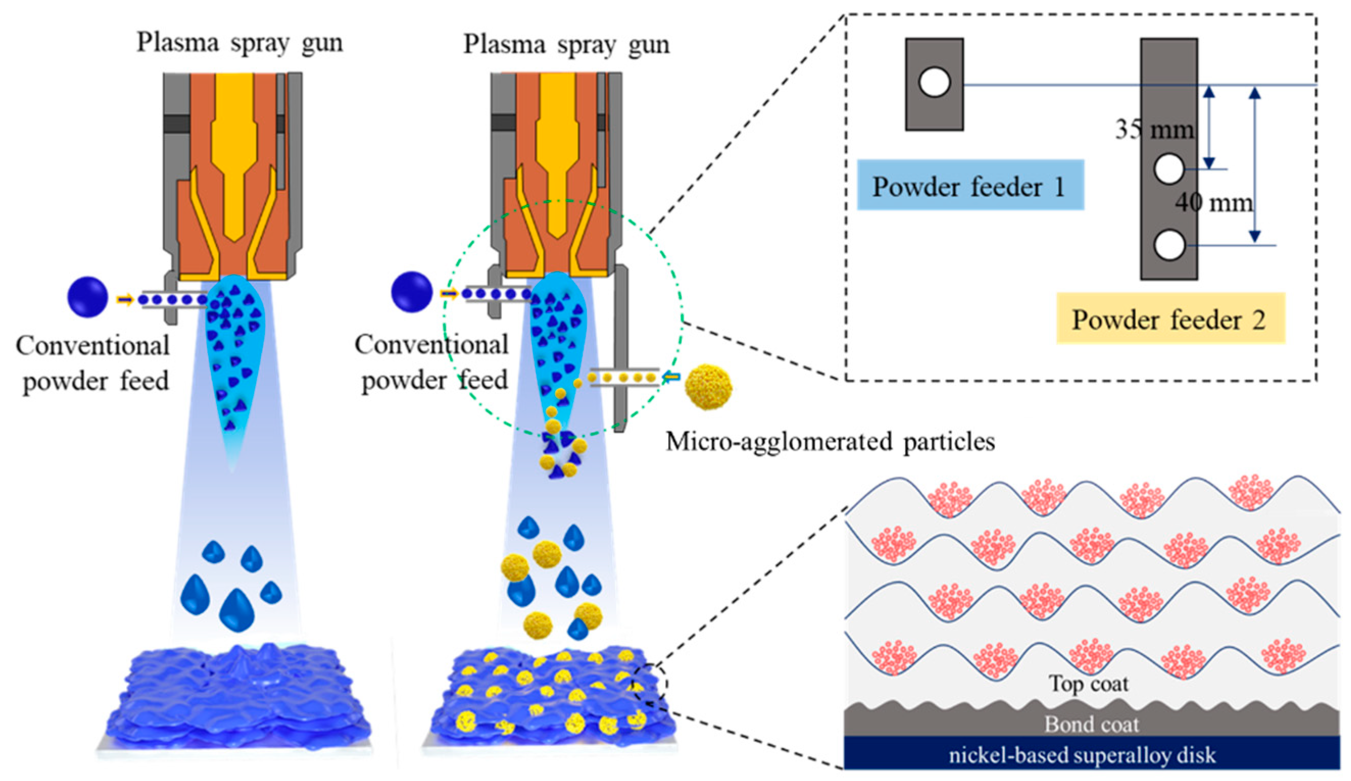
Figure 1. Morphologies of micro-agglomerated particles with particle sizes of 15–45 µm employed for the deposition of top coatings. (a) Low-magnification images of the microstructure. (b) High-magnification images of the microstructure and (c) size distribution.
Coatings 11 00360 g001
Figure 2. Three-dimensional morphology and a graphical study of the Ra parameter of the matrix after sandblasting.
Coatings 11 00360 g002
Figure 3. Schematic diagrams show the processes of controlling the microstructure of the EMAP TBC by adjusting the distance of the powder feeders.
Coatings 11 00360 g003
Figure 4. Micro-agglomerated particles embedded in matrix coating with different contents and distributions: (a) less content and non-uniform distribution, (b) excessive and unevenly distributed, and (c) moderate content and uniform distribution.
Coatings 11 00360 g004
Figure 5. Schematic diagrams showing the method used to measure the distribution distance of the particles embedded in the matrix coating: (a) vertical distance and (b) horizontal distance.
Coatings 11 00360 g005
Figure 6. Separation distance distribution of the particles embedded in the matrix coating: (a) EMAP TBC prepared with different distances between powder feeder 1 and powder feeder 2, and (b) EMAP TBC prepared with different feeding rates for powder feeder 1 and powder feeder 2.
Coatings 11 00360 g006
Figure 7. Fracture morphologies of the as-sprayed TBC and the TBCafter sintering at 1300 °C for 40 h: (a) conventional TBC as-sprayed, (b) conventional TBC after sintering, (c) EMAP TBC as-sprayed, and (d) EMAP TBC after sintering.
Coatings 11 00360 g007
Figure 8. Schematic diagrams show the method used for measuring the proportion of particles embedded in the matrix coating: (a) as-sprayed EMAP TBC, and (b) EMAP TBC after sintering at 1300 °C for 40 h.
Coatings 11 00360 g008
Figure 9. Evolution of the embedded particle structure of the coatings prepared in two different systems during a thermal exposure test: (a) EMAP TBC prepared with different distances between powder feeder 1 and powder feeder 2, and (b) EMAP TBC prepared with different feeding rates for powder feeder 1 and powder feeder 2.
Coatings 11 00360 g009
Figure 10. Evolution of the Vickers microhardness of the conventional TBC and EMAP TBCs with thermal exposure duration under 1300 °C: (a) conventional TBC and EMAP TBCs prepared with a different distance between powder feeder 1 and powder feeder 2. (b) Conventional TBC and EMAP TBCs prepared with different feeding rates of powder feeder 1 and powder feeder 2.
Coatings 11 00360 g010
Figure 11. Comparison of the lifetime between the TBC specimens fabricated with a conventional process and the new process with cyclic conditions in FCT.
Coatings 11 00360 g011
Figure 12. The microstructure of the spraying state of the conventional TBC and EMAP TBCs prepared by different spraying parameters: (a) conventional TBC, (b) EMAP TBC (d = 35 mm, 12 g/min + 16 g/min), (c) EMAP TBC (d = 40 mm, 12 g/min + 16 g/min), and (d) EMAP TBC (d = 35 mm, 16 g/min + 16 g/min).
Coatings 11 00360 g012
Figure 13. Cross-sectional microstructure of the TBCs after thermal cycle test: (a,e) conventional TBC, (b,f) EMAP TBC (d = 35 mm, 12 g/min + 16 g/min), (c,g) EMAP TBC (d = 40 mm, 12 g/min + 16 g/min), and (d,h) EMAP TBC (d = 35 mm, 16 g/min + 16 g/min).
Coatings 11 00360 g013
Table 1. Plasma spraying parameters for the deposition of conventional TBC and EMAP TBCs.
CategoryDistance Between the Two Powder Feeders (mm)Conventional Powder Feeding Rate (g/min)Second-Phase Powder Feeding Rate (g/min)
Conventional TBC8
EMAP TBC 1351216
EMAP TBC 2401216
EMAP TBC 3351616
Publisher’s Note: MDPI stays neutral with regard to jurisdictional claims in published maps and institutional affiliations.

