Article

Sensitivity of Corrosion Behavior for Fe-Based Amorphous Coating to Temperature and Chloride Concentration

1
Shenyang National Laboratory for Materials Science, Institute of Metal Research, CAS, Shenyang 110016, China
2
School of Materials Science and Engineering, University of Science and Technology of China, Shenyang 110016, China
*
Authors to whom correspondence should be addressed.
The authors contribute equally to this manuscript.
Coatings 2021, 11(3), 331; https://doi.org/10.3390/coatings11030331
Submission received: 29 January 2021 / Revised: 4 March 2021 / Accepted: 6 March 2021 / Published: 14 March 2021
(This article belongs to the Special Issue Corrosion and Electrochemical Behavior of Metals Coating)

Abstract

:
The effects of solution concentration and temperature on the electrochemical behavior of the Fe-based amorphous (AMCs) coatings in NaCl solution were studied by using conventional electrochemical measurement and XPS analysis. Results indicated that as solution concentration and temperature increased, the current density for the Fe-based AMCs increased and the pitting potential decreased. This reduced corrosion resistance was derived from the decreased passivation index and polarization resistance, which contributed to the decrease of the induction time (tm) for the initiation of corrosion pit. The passive films formed on Fe-based AMCs exhibit two types’ semiconductors higher and lower the flat band potential. The decrease of protectiveness of the passive film was mainly correlated with the reduction of Cr2O3 content, the increase of carrier density and the decrease of the work function (WF).

1. Introduction

Fe-based amorphous coatings (AMCs) are potential coatings against corrosion and wear for many applications in shipbuilding, petroleum, nuclear industry, and other fields owing to their unique structure and excellent combination properties [1,2,3,4,5]. Amorphous alloy is structurally and compositionally uniform and is a lack of typical crystalline phases and structural defects. Thus, a uniform passive film is readily formed on it and render it an outstanding corrosion performance. However, the corrosion property of the amorphous coating is strongly dependent on the coating defects inevitably introduced during the coating preparation [6,7,8,9,10,11]. Consequently, it is necessary to conduct in-depth research on the corrosion performance of Fe-based AMCs.
In recent years, numerous research has been done on the corrosion performance and corrosion mechanism of AMCs, which has promoted the development of these new materials. Zhou et al. investigated the corrosion of the Fe-based AMCs in HCl and H2SO4 solutions, and found that the coating had a wide passivation zone without localized corrosion in these two acid solutions [12]. Farmer et al. found that some vitrified areas in the coatings are prone to rust spots during salt spray corrosion [1]. Furthermore, it was also found that the more amorphous phase the coating contained, the better protective properties the coating had [13,14,15,16]. As for the corrosion mechanism of Fe-based AMCs, it was well recognized that Cr-depleted zone among the intersplats in the coating was the major reason for the initiation of pitting corrosion of the coating [8,10]. Moreover, the relationship between coating porosity and the corrosion behavior has been also studied in detail [9,10]. In their research, the authors believed that the sensitivity of the through pores to the thickness of the coating promoted corrosion of the matrix, rather than the pitting corrosion caused by the through-porosity, which also reduced the long-term corrosion resistance. It was noteworthy that Wu et al. have investigated the corrosion performance of Fe-based AMCs under dry and wet cyclic conditions simulated marine environments for coating practical applications [17]. Understanding the corrosion behavior of Fe-based AMCs in the application environment is of great importance to drive the application of this kind of coating. In the practical service condition of the coating, the concentration of the aggressive ion and the temperature is not constant. However, there is still a lack of relevant reports on the corrosion mechanism and behavior of Fe-based AMCs at different solution concentrations and temperatures. The concentration of aggressive ion (e.g., chloride ion) and the solution temperature probably change the composition and the properties of the passive film on Fe-based AMCs and then change the corrosion behavior of the coating. But the mechanism of this effect has not yet been fully understood.
The objective of this study was to investigate the corrosion behavior of Fe-based AMCs in NaCl solution with various concentration and temperatures. The influence of temperature and chloride ion concentration on the corrosion behavior and the components and electrochemical characteristics of the film would be studied using conventional electrochemical methods and XPS analysis. The electrical characteristics of the passive film on the AMCs would also be discussed.

2. Materials and Methods

2.1. Coating Preparation

Fe-based amorphous alloy powders were prepared by gas atomization using the master alloy with a nominal composition Fe54.5Cr18.4Mo13.9Mn2.0W5.8B3.2C0.9Si1.3 (wt.%). Blended amorphous powders (20–53 μm) and commercial Al2O3 powders (20–65 μm) in a ratio (volume) of 1:1. The addition of Al2O3 powder aims to decrease the coating porosity.
The low carbon steel with the size of 350 × 150 × 5 mm3 was selected as the substrate material for the amorphous coated. The Fe-based AMCs were prepared using the AcuKote supersonic flame spraying system equipped with the American Komick AK-07 spray gun (Kermetico, CA, USA). Prior to spraying, a series of treatments are applied on the substrate such as surface polishing, acetone cleaning, drying, and sand blasting. The detailed thermal spraying process parameters were given as air pressure 90 psi, fuel pressure 83 psi, spraying distance 180 mm, and the spray gun traverse velocity 900 mm/s. The as-sprayed coatings were cut into 5 × 5 × 5 mm3 coupons for the subsequent structure characterization and electrochemical experiments.

2.2. Electrochemical Tests

A traditional three-electrode was used for the electrochemical tests and all potential were against the SCE. All experiments have been carried out in aerated 0.35 wt.%, 1.11 wt.%, 3.5 wt.% NaCl solution with different temperatures (30 °C, 50 °C and 70 °C) using the EG&G Princeton Applied Research model 2273 electrochemical workstation. The electrode was immersed in the solution for about 1 h to reach a relatively stable state before the electrochemical tests. The scan rate of potentiodynamic polarization is 0.333 mV/s, and the scan step size is 1 mV, starting from −0.1 V versus open circuit potential (−0.1 VOCP) to the anodic direction until the potential reached the 1.2 V relative to the reference electrode (1.2 VSCE). The potential of 0 VSCE was selected for the potentiostatic polarization tests. For the electrochemical impedance spectroscopy (EIS) test, a sine signal with an amplitude of 10 mV was selected with the frequency from 100 kHz to 10 mHz. The EIS data was analyzed by the software of ZVIEW 3.1. Mott–Schottky tests were determined at a scan rate of 20 mV/s from the anodic potential close to the pitting potential to the cathodic (−1.2 VSCE) direction with frequency of 1 kHz.

2.3. Microstructure Characterization

The structure of the coatings were inspected by X-ray diffraction (XRD), Cu Kα radiation was used at 180 mA and 50 kV with 2θ range from 20° to 80°. The morphology of the Fe-based AMCs was determined by Zeiss Supra 55 scanning electron microscope (SEM) (Carl Zeiss AG, Jena, Germany). Before SEM observation, the tested coating surface was ground and polished.

2.4. XPS Characterization

The ESCALAB250 photoelectron spectrometer (Thermo, Waltham, MA, USA). (hν = 1486.6 eV) excited by Al Kα was used to analyze the change of composition in passive film after constant potential measurement of the coating sample. The standard Scofield sensitivity factor was used to calculate quantitative information from the survey spectrum. The binding energy was calibrated by carbon pollution, and the peak value of carbon 1s is 284.6 eV. The passive film was sputtered by ion beam with 2 kv, 2 μA argon ions with 0.2 nm/s, and the depth distribution of the passive film was characterized.

3. Results

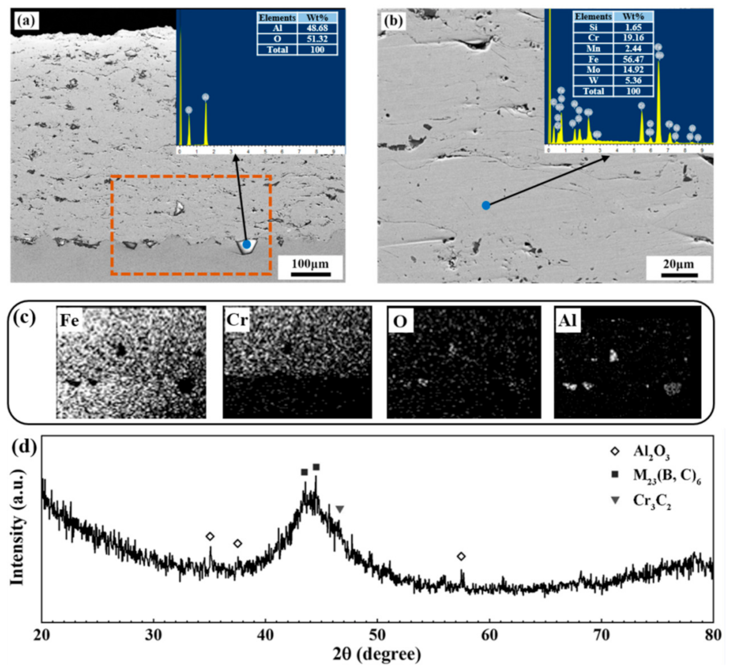
3.1. Characterization of the AMCs

The polished cross-sectional morphology and XRD pattern of the Fe-based AMCs are depicted in Figure 1. The interface between substrate and coating is well bonded and the coating is relatively dense. The EDS results both the point scanning (inset in Figure 1a) and the mapping (Figure 1c) prove that the bright phase in Figure 1a is unmelted Al2O3 particles that remain in the coating during spraying process. Some pores and interparticle oxide layers, also known as intersplats, existed in the coatings (Figure 1b). In the XRD pattern shown in Figure 1d, one obvious broad hump is observed, implying the coatings are basically amorphous in structure. Few very weak diffraction peaks could be attributed to the deliberately-added Al2O3 and carbide of M23C6 (M is Fe, Cr, Mn, Mo).

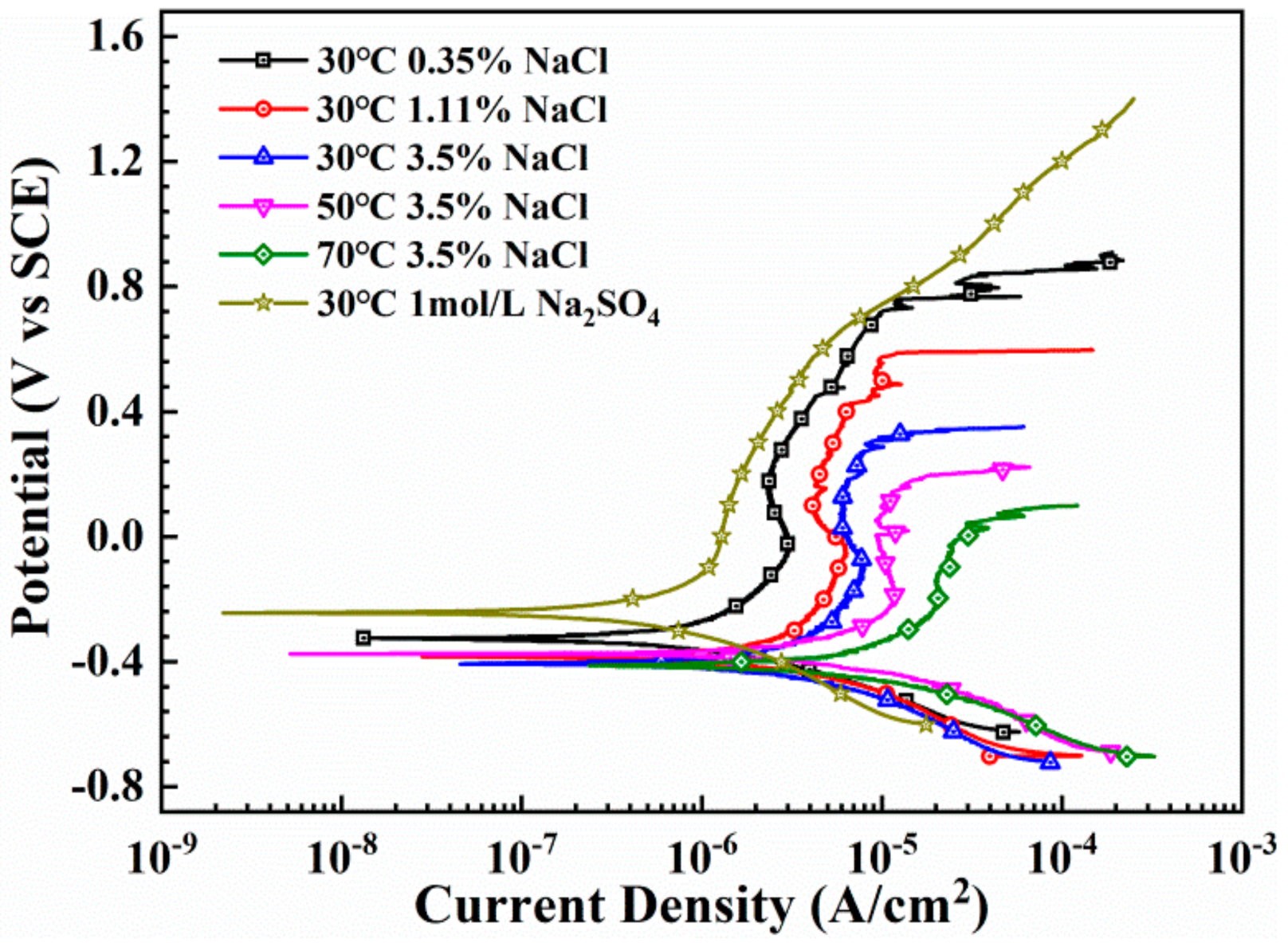
3.2. Anodic Polarization Behavior

The polarization results of the Fe-based AMCs in 1 mol/L Na2SO4, 3.5 wt.%, 1.11 wt.%, and 0.35 wt.% NaCl solution at the temperature range of 30–70 °C are displayed in Figure 2. All the polarization curves exhibit a well-defined passivation characteristic, indicating that the Fe-based AMCs could form a passive film at all solution concentration and temperatures. There is no pitting corrosion for the Fe-based AMCs in 1 mol/L Na2SO4 solution. Nevertheless, with the addition of chloride ions, pitting corrosion occurs. As temperature and solution concentration increase, both corrosion current density and passive current density of Fe-based AMCs increase obviously. While the pitting potential drops from 0.8 VSCE (0.35% wt.% NaCl, 30 °C) to 0.1 VSCE (3.5% wt.% NaCl, 70 °C). Accordingly, the protective characteristic of the passive film degrades with increasing solution concentration and temperature.

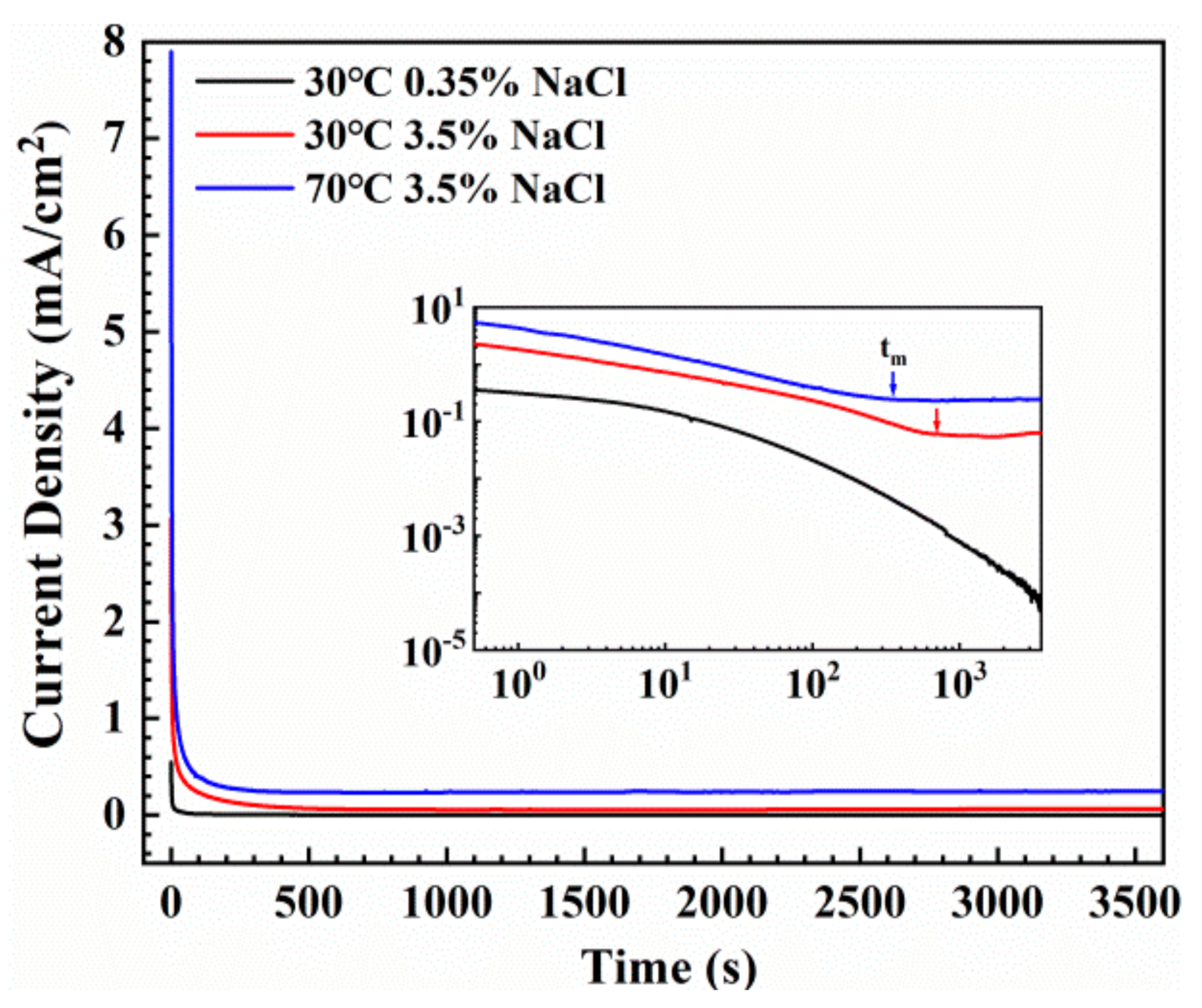
3.3. Potentiostatic Polarization Tests

The passivation behavior of the Fe-based AMCs in three typical conditions (30 °C 0.35 wt.% NaCl, 30 °C 3.5 wt.% NaCl, 70 °C 3.5 wt.% NaCl) are studied in detail in this work. Figure 3 shows the current-time transient states and log i-log t charts for Fe-based AMCs samples at various solution concentration and temperatures at 0 VSCE potential. The current density values recorded in the potentiostatic test is the sum current generated by the growth, formation and destruction of the Fe-based AMCs film in the solution. It is initially observed that in these three measurements, the current drops rapidly due to the nucleation and growth of the passive film. As time further increases, a relatively stable current density (iss) will be generated, indicating that a passive film is formed on the surface of Fe-based AMCs. The iss is observed to increase as the solution concentration and temperature elevate, indicating a deterioration in the protectiveness of the passive films.
The log i-log t charts for Fe-based AMCs samples in the NaCl solution with various concentration and temperatures are displayed in Figure 3. The transient process of anode current is divided into two stages. On a logarithmic scale, the anode current density decreases linearly with time, which can be obviously seen in the transient process at 30 °C 0.35 wt.% NaCl solution. The decrease in current density is owing to the rate of passivation of the oxide film controlling the rate of dissolution on the exposed surface [18,19,20]. Nevertheless, as the temperature and concentration increase, starting from the induction time (tm), the log i-log t curve shows an upward trend, which may be due to the rupture of the film caused by the growth of pits. It can be clearly observed from the Figure 3 that the induction times (tm) decrease with temperature rising (arrow), implying that the concentration and temperature have a negative effect on the corrosion resistance of the film on the Fe-based AMCs.
The empirical formula of the time–current density relationship can be described as equation [18]:
i = Atn
In the equation, A is a constant and n is the passivation index (in a particular alloy-environment system is a constant). The slope of the linear region of log i-log t graph can represent the parameter n (as shown in Figure 3), which is considered to be an indicator of the formation rate of the passive film on the new metal surface when the anode potential is applied [18,21,22]. According to the literature [23,24], n = 1 means that a dense, highly protective film is formed, and n = 0.5 means that there is a porous film formed by the process of dissolution and precipitation. The values of n for Fe-based AMCs samples are summarized in Table 1. The decrease of this parameter with solution concentration and temperature implies the passive film grows more slowly and its protectiveness decrease with increasing solution concentration and temperature.

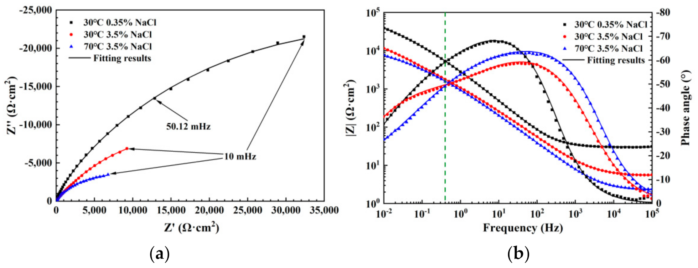
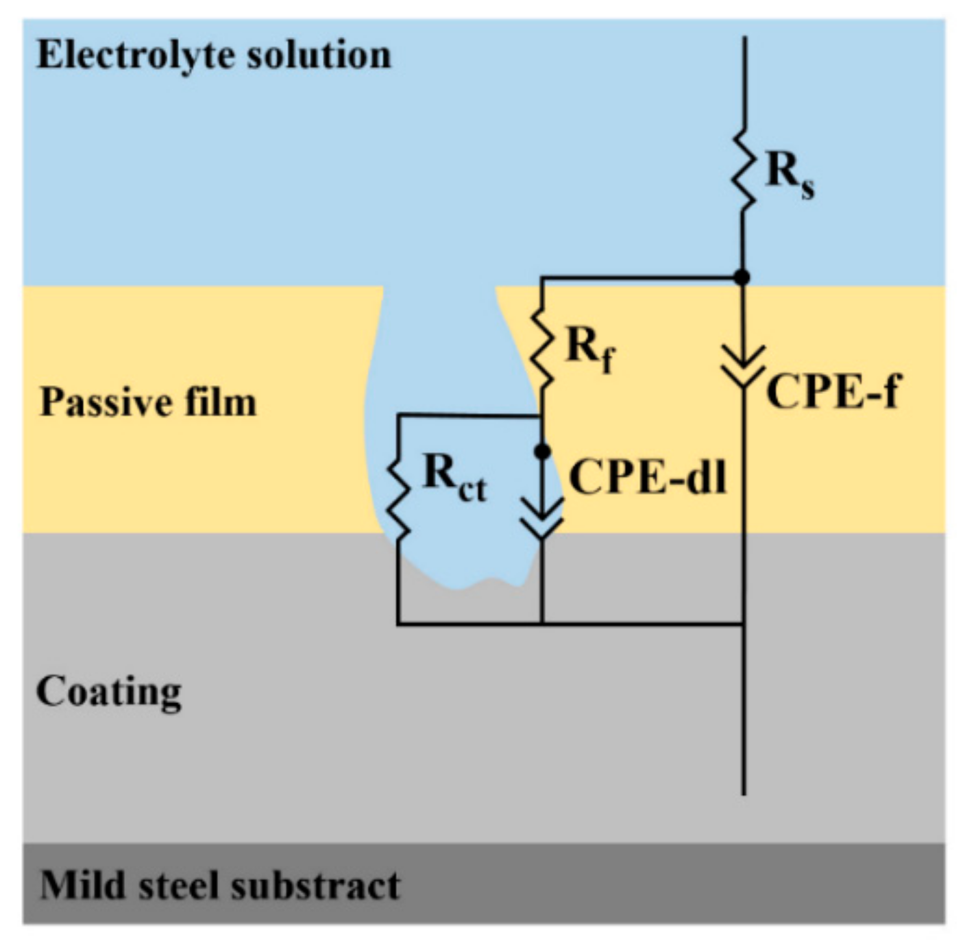
3.4. Electrochemical Impedance Analysis

Figure 4 shows the impedance spectra in both Nyquist and Bode/Bode-phase plots obtained at three conditions. As depicted in the Nyquist diagram (Figure 4a), the impedance spectra consist of a high-frequency intercept (Rs) corresponding to the electrolyte resistance and a main capacitive loop at lower frequencies. When the concentration and temperature increase, the radius of the capacitive loop becomes smaller, suggesting a lower polarization resistance. It can be seen from the Bode impedance amplitude diagram in Figure 4b that the overall impedance reduction order of the three coatings is: 30 °C, 0.35 wt.% NaCl > 30 °C, 3.5 wt.% NaCl > 70 °C, 3.5 wt.% NaCl. The Bode magnitude diagram (Figure 4a) shows that as the solution concentration and temperature increase, the low-frequency impedance decreases. Theoretically, the low-frequency impedance reflects the protective performance of the coating. The Bode phase angle diagram shows that as the solution concentration and temperature increase, the phase angle value decreases, which also indicates that the corrosion resistance decreases. These results reflect that the solution concentration and temperature reduce the polarization resistance of the Fe-based AMCs.
The impedance data of the three test samples have two time constants, corresponding to the double layer and the coatings. Therefore, a two RC equivalent circuit (Figure 5) is applied to fit the EIS data. Since pure capacitors are difficult to apply to actual electrochemical processes, constant phase elements (CPE) are often used instead of capacitors [25]. In the equivalent circuit, the time constant at high frequency (Rf, CPE-f) is corresponding to the passive film, which is represented by the admittance of the film (CPE-f) and its resistance (Rf). The time constant at low frequency (Rct, CPE-dl) is related to the active surface area and it is represented by the admittance associated with the capacitance of the double layer and the charge transfer resistance (Rct) in the active areas. The fitting parameters for the EIS results are summarized in Table 2. As the concentration and temperature increase, the values of Rf and Rct exhibit obvious decrease, indicating that the deteriorated corrosion properties for the Fe-based AMCs.

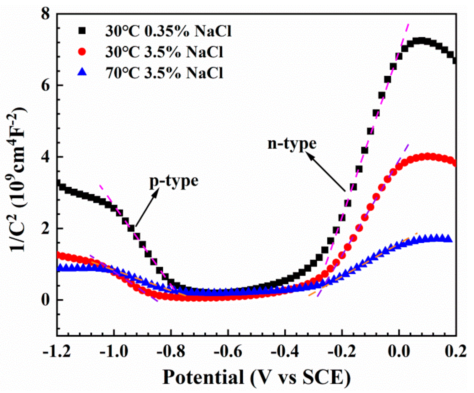
3.5. Mott–Schottky Results

Generally, passive films exhibit semiconductor characteristic [26,27,28]. Mott–Schottky tests was conducted to clarify the effects of the solution concentration and temperature on the semiconductor properties of the passive films.
According to Mott–Schottky theory, in this work, the capacitance could be given as follow [29]:
1 C 2 = 2 ε ε 0 e A N D E E FB k T e    n type
1 C 2 = 2 ε ε 0 e A N A E E FB k T e    p type
where NA/ND is the acceptor/donor density in the passive film, ε0 the vacuum permittivity, ε the dielectric constant of the film, EFB is the flat band potential.
The Mott–Schottky curves for the passive film on the Fe-based AMCs in NaCl solution at various concentration and temperatures is displayed in Figure 6. Two straight regions could be revealed in this plot. The positive slope for the potential range higher than EFB reveals an n-type semiconductor. Meanwhile, the negative slope for the potential range lower than EFB suggests that the film behaved like a p-type semiconductor. In this work, based on the n-type straight line (basically in the passivation region) by the following: E F B = E 0 k T e , where E0 is the potential at which C−2 = 0, the donor density, acceptor density as well as the EFB for the passive film are obtained by the slope of straight regions of the Mott–Schottky plots using ε = 15.6 [30] and summarized in Table 3. The results indicate that the acceptor and donor density increase obviously while the EFB decreases drastically with increasing solution concentration and temperatures.

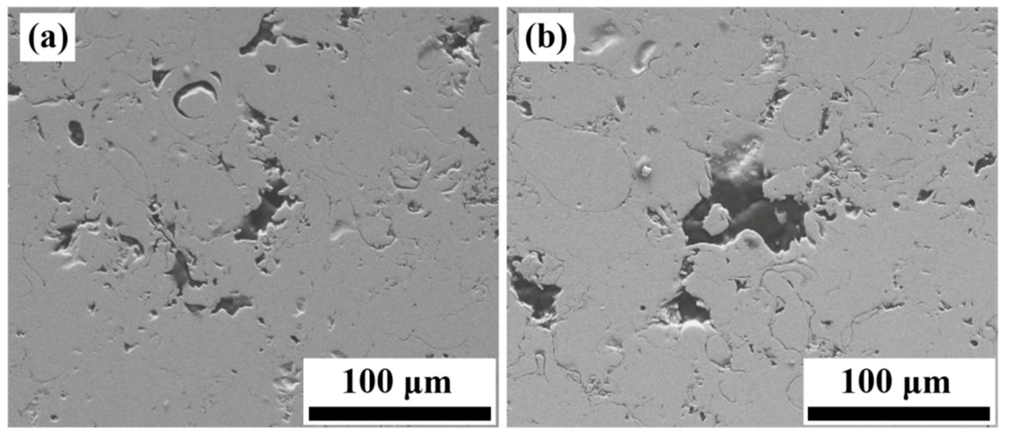
3.6. Corrosion Morphologies of Fe-Based AMCs
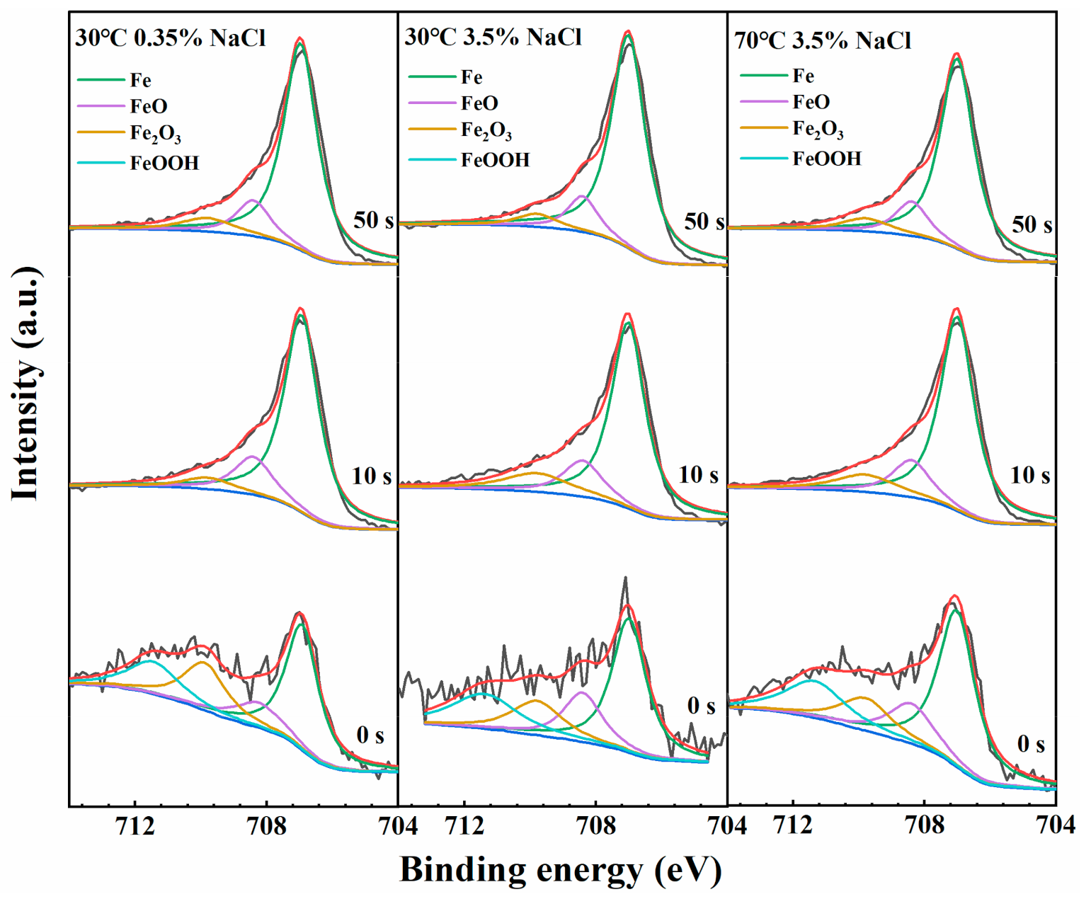
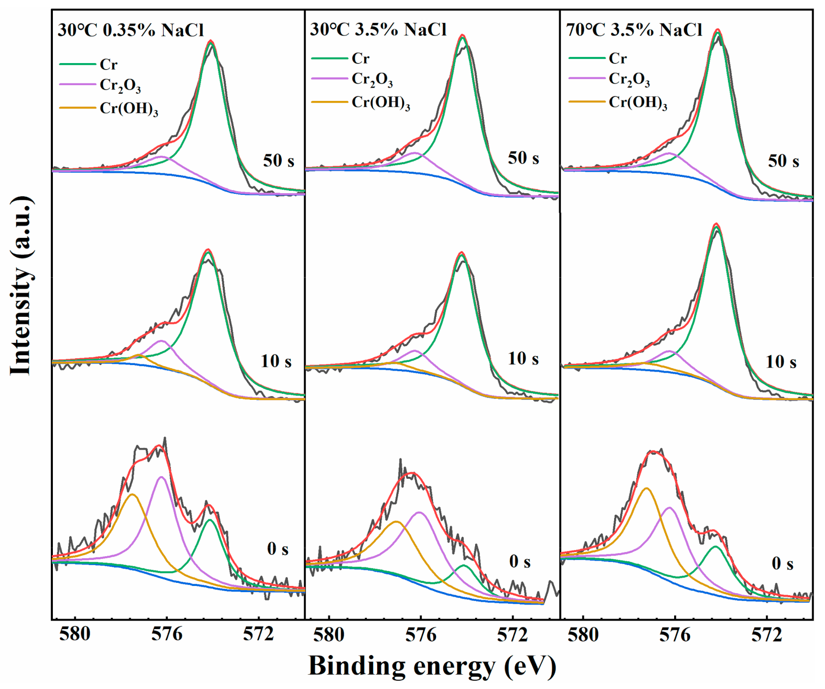
The corrode morphologies of the Fe-based AMCs after potentiodynamic polarization tests at 30 °C 0.35 wt.% NaCl and 70 °C 3.5% NaCl solution are displayed in Figure 7. The cross section for the two coatings has been corroded into several pits, and a lot of corrosion products form in and around them. Furthermore, the size of the pits for the sample polarization tested in 70 °C 3.5% NaCl solution (Figure 7b) are much larger than that for the sample tested in 30 °C 0.35 wt.% NaCl solution (Figure 7a), implying that the coating sample has undergone a serious corrosion at a relatively high solution concentration and temperature.

3.7. XPS Analysis

To deeply analysis the composition of the passive films, the XPS experiments are conducted to investigate the different states for the major elements Fe and Cr. Figure 8 displays the XPS spectra of Fe 2p3/2 in the film on the AMCs in NaCl solution at 30 °C 0.35%, 30 °C 3.5% and 70 °C 3.5% with sputtering time. The binding energy for each state of Fe for the Fe-based AMCs at different solution concentration and temperature is consistent. As observed in Figure 8, the Fe 2p3/2 spectra are divided into the metallic Fe (706.8 eV), FeO (708.4 eV), Fe2O3 (710.0 eV) and FeOOH (711.6 eV). In general, the thickness of passive film in three different solution environments is basically the same. The Fe 2p3/2 and Cr 2p3/2 photoelectron peak assignment and relative content (at.%) for the species at different solution concentration and temperatures are summarized in Table 4. The results indicated that the total amount of oxidized Fe in the passive film on the Fe-based AMCs decreases with the increase of solution concentration. This reflects the Fe-rich oxide/hydroxide outer layer of the passive film dissolves faster in the high chloride concentration solution.
Figure 9 depicts the detailed Cr 2p3/2 spectra in the film on the Fe-based AMCs in NaCl solution at 30 °C 0.35%, 30 °C 3.5% and 70 °C 3.5% with various sputtering times. As observed in Figure 9, the Cr 2p3/2 spectra are mainly composed of the Cr metal (574.0 eV) and Cr2O3 (576.4 eV) and Cr(OH)3 (578.2 eV). As the sputtering time increase, the signals of Cr metal enhance while the signals Cr oxide and hydroxide weaken. The similar tendency occurs on the metallic Fe and oxidized Fe peaks. As can be seen from the values in Table 4, as the solution temperature increases, the ratio of oxidized Cr to oxidized Fe is similar for the passive film at different sputtering time. But the relative content of the more protective Cr2O3 decreases while the relative content of Cr(OH)3 increases. Thus, the passive film formed at the high temperature conditions is relatively unstable and the corresponding Fe based AMCs in the high temperature shows a lower corrosion resistance.
It is worth noting that chloride is found in the surface films on the Fe-based AMCs after two-day immersion in the three solutions (Figure 10a). The chloride atomic concentration calculated by the XPS results is 1.8% in 30 °C 0.35% NaCl, 2.9% in 30 °C 3.5% NaCl and 3.3% in 70 °C 3.5% NaCl solution, as presented in Figure 10b. This implies that the penetration of Cl into the films is accelerated at a relatively higher concentration and temperature NaCl solution.

4. Discussion

4.1. Effects of Concentration of Chloride Ion and Solution Temperature on the Passive Behavior

In the NaCl solution, the Cl competes with OH for adsorption on the sample surface. Once Cl adsorbs on the surface, the activation energy for the Me–Cl complexes transfer to the solution is decreased due to the less strongly bound to the substrate [31]. Consequently, the rate of localized dissolution is accelerated, thus the growth of the passive film is weakened. This will cause the passive film to be thinner and localized depassivation occur in the weak points. In this study, Polarization curves (Figure 2) show that Fe-based AMCs can form passive films in NaCl solutions with concentrations of 0.35% and 3.5% at 30–70 °C. The drop of the pitting potential and the increment of the passive current density reveal that the safeguard of the passive film degrade with elevating the NaCl solution concentration and temperature. Furthermore, the high chloride concentration and high temperature also decrease the passivation index n calculated (Table 1) from the potentiostatic tests (Figure 3) and lead to the passive film formation more slowly. The corrosion resistance of the Fe-based AMCs decreased distinctly with elevating solution concentration and temperature (Table 2), this may cause the current density measured in polarization to be higher than normal.
The XPS results revealed that with the increase of solution concentration, the Fe species in oxidation state decreases but the corresponding Cr species increases in the passive film formed on the Fe-based AMCs. This is because when the electrode immerse and contact with the solution, an electric double layer is formed at the interface between the solution and the coating surface. Based on Stern’s bilayer theory, the electric bilayer consists of a dense layer and a diffused layer. Usually, the diffusion layer become thinner with the accelerate of ion concentration. Therefore, in a concentrated NaCl solution, the drop of the potential for this layer will be sharper, resulting in a higher electrical strength. This effect will accelerate the reaction rate and the film formation rate at the initial stage of film nucleation and growth, resulting in a decrease in the Fe content of oxidation state. Due to the high growth rate of the film and the limited time for atom/ion diffusion to the correct position, more defects will be generated in the passive film, and the carrier density will increase accordingly, and thus the protective characteristic of the passive film will decline. When the solution temperature increases, the rate of the film growth and dissolution increase. However, the relative content of more protective Cr2O3 decreases and the loose Cr(OH)3 increases (XPS results in Table 4), this will lead to the degeneration of the protection characteristic of the passive film and an increase in the passivation current.

4.2. The Evolution of Band Structure of the Passive Film

The passive films are widely perceived as highly doped semiconductor films, and their growth behavior as well as protective properties are determined by its conductivity. Generally, a lower carrier density corresponding to the lower conductivity and good protectiveness of the passive film [32]. In this study, the results of ND indicate that the coating sample test in 0.35% NaCl with 30 °C solution has the lowest ND, implying the best protective performance of its passive film. With the increase of solution concentration and temperature, the ND value gradually increases, reflecting that the protection of the passive film decreases. The results of EIS measurements also indicated that the coating sample in 0.35% NaCl solution at 30 °C has the largest film resistance, while the coating sample in 3.5% NaCl solution at 70 °C has the lowest film resistance. These results are consistent with the analysis of polarization tests and Mott–Schottky results.
Furthermore, the evolution of EFB present a similar tendency with ND. EFB is the potential without a net transfer of charge and band bending. Based on previous work, the Fermi level (EF) and the EFB has an inverse relationship of EF = −EFB Thus, the EF can be obtained easily by the value of EFB. Based on the values of EFB, it can be inferred that the coating sample (0.35% NaCl at 30 °C) has a more negative EF, followed by the coating sample (3.5% NaCl at 30 °C), and the coating sample in 3.5% NaCl solution at 70 °C has a more positive EF. What is more, it is well known that the corrosion process is accompanied by the transfer of the electron. Generally, for a semiconductor, the more positive value of EF indicates the transformation of electron easier, and the corrosion resistance will be decreased. [33].
Meanwhile, the work function (WF) can be obtained by the equation as follows:
WF = e × (EVEF)
where EV is the level of vacuum. Figure 11 shows the influence of solution concentration and temperatures on the evolution electronic structure and WF for the Fe-based AMCs samples. For the Fe-based AMCs samples in 0.35% NaCl solution at 30 °C, the WF is increased compared to the coating sample in 3.5% NaCl solution at 30 °C. In this condition, the transfer of electron is harder owing to the higher energy barrier, this will promote the improving of the corrosion resistance. Furthermore, the lowest WF for the sample within 3.5% NaCl solution at 70 °C indicates the lowest corrosion resistance of this coating sample.

5. Conclusions

The effects of solution concentration and temperature on the corrosion performance of Fe-based AMCs were studied by conventional electrochemical test, EIS combined with XPS. The conclusions could be summarized as follows:
  • The fabricated coating was basically amorphous state and had a homogeneous microstructure. As temperature and solution concentration increased, the passive current for the Fe-based AMCs increased and the pitting potential decreased obviously. The increase of temperature and solution concentration decreased the passivation index and the polarization resistance and deteriorated the protective performance of the passive film, which contributed to the decrease of induction time (tm) for the growth of corrosion pit.
  • In the potential ranges below and above the EFB, the passive film formed on the Fe-based AMCs exhibited a p-type and n-type semiconductor properties, respectively. The declining corrosion resistance for the Fe-based AMCs in relatively higher temperature and higher concentration NaCl solution was derived from the reduced ratio of Cr2O3, the increase of carrier densities and the decrease of WF for the passive film formed in this condition.

Author Contributions

Conceptualization, W.L., S.Z. and B.Y.; Validation, W.L., D.W., Q.W., F.Y., T.L., Y.S., S.Z. and B.Y.; methodology, W.L., D.W. and S.Z.; investigation, W.L., T.L., Y.S. and S.Z.; resources, S.Z. and B.Y.; data curation, W.L. and Q.W.; writing—original draft preparation, W.L., D.W., Q.W. and F.Y.; writing—review and editing, W.L., S.Z. and B.Y.; supervision, W.L.; project administration, T.L.; All authors have read and agreed to the published version of the manuscript.

Funding

This work was supported by the National Key Research and Development Program of China (No. 2018YFB1105803) and National Natural Science Foundation of China (Nos. U1908219 and 51701214).

Data Availability Statement

All data in this work are available on request by contact with the corresponding author.

Acknowledgments

The authors are grateful for the support of the Shenyang National Laboratory for Materials Science, Institute of Metal Research.

Conflicts of Interest

The authors declare no conflict of interest.

References

  1. Farmer, J.C.; Choi, J.S.; Saw, C.; Haslam, J.; Day, D.; Hailey, P.; Lian, T.; Rebak, R.; Perepezko, J.; Payer, J.; et al. Iron-Based Amorphous-Metals: High-Performance Corrosion-Resistant Material (HPCRM) Development. Metall. Mater. Trans. A 2009, 40, 1289–1305. [Google Scholar] [CrossRef]
  2. Bolelli, G.; Bonferroni, B.; Laurila, J.; Lusvarghi, L.; Milanti, A.; Niemi, K.; Vuoristo, P. Micromechanical properties and sliding wear behaviour of HVOF-sprayed Fe-based alloy coatings. Wear 2012, 276–277, 29–47. [Google Scholar] [CrossRef]
  3. Otsubo, F.; Era, H.; Kishitake, K. Formation of amorphous Fe-Cr-Mo-8P-2C coatings by the high velocity oxy-fuel process. J. Therm. Spray Technol. 2000, 9, 494–498. [Google Scholar] [CrossRef]
  4. Kobayashi, A.; Yano, S.; Kimura, H.; Inoue, A. Mechanical property of Fe-base metallic glass coating formed by gas tunnel type plasma spraying. Surf. Coat. Technol. 2008, 202, 2513–2518. [Google Scholar] [CrossRef]
  5. Zhang, H.; Hu, Y.; Hou, G.; An, Y.; Liu, G. The effect of high-velocity oxy-fuel spraying parameters on microstructure, corrosion and wear resistance of Fe-based metallic glass coatings. J. Non·Cryst. Solids 2014, 406, 37–44. [Google Scholar] [CrossRef]
  6. Sadeghimeresht, E.E.; Markocsan, N.; Nylén, P. Microstructural characteristics and corrosion behavior of HVAF- and HVOF-sprayed Fe-based coatings. Surf. Coat. Technol. 2017, 318, 365–373. [Google Scholar] [CrossRef]
  7. Wu, N.C.; Chen, K.; Sun, W.H.; Wang, J.Q. Correlation between particle size and porosity of Fe-based amorphous coating. Surf. Eng. 2018, 1–9. [Google Scholar] [CrossRef]
  8. Zhang, C.; Chan, K.C.; Wu, Y.; Liu, L. Pitting initiation in Fe-based amorphous coatings. Acta Mater. 2012, 60, 4152–4159. [Google Scholar] [CrossRef]
  9. Zhang, S.D.; Wu, J.; Qi, W.B.; Wang, J.Q. Effect of porosity defects on the long-term corrosion behaviour of Fe-based amorphous alloy coated mild steel. Corros. Sci. 2016, 110, 57–70. [Google Scholar] [CrossRef]
  10. Zhang, S.D.; Zhang, W.L.; Wang, S.G.; Gu, X.J.; Wang, J.Q. Characterisation of three-dimensional porosity in an Fe-based amorphous coating and its correlation with corrosion behaviour. Corros. Sci. 2015, 93, 211–221. [Google Scholar] [CrossRef]
  11. Zhou, Z.; Wang, L.; He, D.Y.; Wang, F.C.; Liu, Y.B. Microstructure and Wear Resistance of Fe-Based Amorphous Metallic Coatings Prepared by HVOF Thermal Spraying. J. Therm. Spray Technol. 2010, 19, 1287–1293. [Google Scholar] [CrossRef]
  12. Zhou, Z.; Wang, L.; Wang, F.C.; Zhang, H.F.; Liu, Y.B.; Xu, S.H. Formation and corrosion behavior of Fe-based amorphous metallic coatings by HVOF thermal spraying. Surf. Coat. Technol. 2009, 204, 563–570. [Google Scholar] [CrossRef]
  13. Koga, G.Y.; Nogueira, R.P.; Roche, V.; Yavari, A.R.; Melle, A.K.; Gallego, J.; Bolfarini, C.; Kiminami, C.S.; Botta, W.J. Corrosion properties of Fe–Cr–Nb–B amorphous alloys and coatings. Surf. Coat. Technol. 2014, 254, 238–243. [Google Scholar] [CrossRef]
  14. Zois, D.; Lekatou, A.; Vardavoulias, M. Preparation and characterization of highly amorphous HVOF stainless steel coatings. J. Alloys Compd. 2010, 504, S283–S287. [Google Scholar] [CrossRef]
  15. Li, D.; Chen, X.; Hui, X.; Wang, J.; Jin, P.; Li, H. Effect of amorphicity of HVOF sprayed Fe-based coatings on their corrosion performances and contacting osteoblast behavior. Surf. Coat. Technol. 2017, 310, 207–213. [Google Scholar] [CrossRef]
  16. Katakam, S.; Santhanakrishnan, S.; Dahotre, N. Fe-Based Amorphous Coatings on AISI 4130 Structural Steel for Corrosion Resistance. JOM 2012, 64, 709–715. [Google Scholar] [CrossRef]
  17. Wu, J.; Cui, J.P.; Zheng, Q.J.; Zhang, S.D.; Sun, W.H.; Yang, B.J.; Wang, J.Q. Insight into the corrosion evolution of Fe-based amorphous coatings under wet-dry cyclic conditions. Electrochim. Acta 2019, 319, 966–980. [Google Scholar] [CrossRef]
  18. Kim, J.-D.; Pyun, S.-I. Effects of electrolyte composition and applied potential on the repassivation kinetics of pure aluminium. Electrochim. Acta 1995, 40, 1863–1869. [Google Scholar] [CrossRef]
  19. Pyun, S.-I.; Lee, E.-J. Effect of halide ion and applied potential on repassivation behaviour of Al-1 wt.%Si-0.5 wt.%Cu alloy. Electrochim. Acta 1995, 40, 1963–1970. [Google Scholar] [CrossRef]
  20. Park, J.-J.; Pyun, S.-I.; Lee, W.-J.; Kim, H.-P. Effect of Bicarbonate Ion Additives on Pitting Corrosion of Type 316L Stainless Steel in Aqueous 0.5 M Sodium Chloride Solution. Corrosion 1999, 55, 380–387. [Google Scholar] [CrossRef]
  21. Qiao, Y.X.; Zheng, Y.G.; Ke, W.; Okafor, P.C. Electrochemical behaviour of high nitrogen stainless steel in acidic solutions. Corros. Sci. 2009, 51, 979–986. [Google Scholar] [CrossRef]
  22. Lee, J.-B. Effects of alloying elements, Cr, Mo and N on repassivation characteristics of stainless steels using the abrading electrode technique. Mater. Chem. Phys. 2006, 99, 224–234. [Google Scholar] [CrossRef]
  23. Galvele, J.R.; Torresi, R.M.; Carranza, R.M. Passivity breakdown, its relation to pitting and stress-corrosion-cracking processes. Corros. Sci. 1990, 31, 563–571. [Google Scholar] [CrossRef]
  24. Szklarska-Smialowska, Z. Pitting corrosion of aluminum. Corros. Sci. 1999, 41, 1743–1767. [Google Scholar] [CrossRef]
  25. Zhao, X.; Zuo, Y.; Zhao, J.; Xiong, J.; Tang, Y. A study on the self-sealing process of anodic films on aluminum by EIS. Surf. Coat. Technol. 2006, 200, 6846–6853. [Google Scholar] [CrossRef]
  26. Hakiki, N.E.; Belo, M.D.; Simões, A.M.P.; Ferreira, M.G.S. Semiconducting Properties of Passive Films Formed on Stainless Steels: Influence of the Alloying Elements. J. Electrochem. Soc. 1998, 145, 3821–3829. [Google Scholar] [CrossRef]
  27. Tsuchiya, H.; Fujimoto, S.; Chihara, O.; Shibata, T. Semiconductive behavior of passive films formed on pure Cr and Fe–Cr alloys in sulfuric acid solution. Electrochim. Acta 2002, 47, 4357–4366. [Google Scholar] [CrossRef]
  28. Fujimoto, S.; Tsuchiya, H. Semiconductor properties and protective role of passive films of iron base alloys. Corros. Sci. 2007, 49, 195–202. [Google Scholar] [CrossRef]
  29. de Gryse, R.; Gomes, W.P.; Cardon, F.; Vennik, J. On the Interpretation of Mott-Schottky Plots Determined at Semiconductor/Electrolyte Systems. J. Electrochem. Soc. 1975, 122, 711–712. [Google Scholar] [CrossRef]
  30. Simões, A.M.P.; Ferreira, M.G.S.; Rondot, B.; Belo, M.D. Study of Passive Films Formed on AISI 304 Stainless Steel by Impedance Measurements and Photoelectrochemistry. J. Electrochem. Soc. 1990, 137, 82–87. [Google Scholar] [CrossRef]
  31. Marcus, P.; Maurice, V.; Strehblow, H.H. Localized corrosion (pitting): A model of passivity breakdown including the role of the oxide layer nanostructure. Corros. Sci. 2008, 50, 2698–2704. [Google Scholar] [CrossRef]
  32. Fernández-Domene, R.M.; Blasco-Tamarit, E.; García-García, D.M.; Antón, J.G. Passivity Breakdown of Titanium in LiBr Solutions. J. Electrochem. Soc. 2013, 161, C25–C35. [Google Scholar] [CrossRef]
  33. Wang, Z.M.; Ma, Y.T.; Zhang, J.; Hou, W.L.; Chang, X.C.; Wang, J.Q. Influence of yttrium as a minority alloying element on the corrosion behavior in Fe-based bulk metallic glasses. Electrochim. Acta 2008, 54, 261–269. [Google Scholar] [CrossRef]
Figure 1. The morphology of the cross-section and the XRD plot of the Fe-based amorphous coatings (AMCs). (a) low magnification image (SEM); (b) local enlarged image; (c) elements mapping; (d) XRD plot.
Coatings 11 00331 g001
Figure 2. Potentiodynamic curves of Fe-based AMCs in NaCl solution with various concentration and temperatures.
Coatings 11 00331 g002
Figure 3. Current–time curve and log i-log t charts for Fe-based AMCs at various solution concentration and temperatures at potential of 0 VSCE.
Coatings 11 00331 g003
Figure 4. Electrochemical impedance spectroscopy (EIS) behavior and fitting results of the Fe-based AMCs coating samples. (a) Nyquist plots; (b) Bode/Bode-phase plots.
Coatings 11 00331 g004
Figure 5. Relevant electrical circuit analogs used to simulate EIS spectra of Fe-based AMCs immersed in NaCl solution.
Coatings 11 00331 g005
Figure 6. The Mott–Schottky curves for the films on Fe-based AMCs samples in NaCl solution with various concentration and temperatures.
Coatings 11 00331 g006
Figure 7. The morphologies of the cross section for the Fe-based AMCs after potentiodynamic polarization tests. (a) 30 °C 0.35% NaCl solution and (b) 70 °C 3.5% NaCl solution.
Coatings 11 00331 g007
Figure 8. The detailed XPS spectra of Fe 2p3/2 in the film on Fe-based AMCs with different sputtering times in the NaCl solution with various concentration and temperatures.
Coatings 11 00331 g008
Figure 9. The detailed XPS spectra of Cr 2p3/2 in the film on the Fe-based AMCs with different sputtering times in the NaCl solution with various concentration and temperatures.
Coatings 11 00331 g009
Figure 10. The detailed XPS spectra of Cl 2p (a) and the chloride atomic concentration determined by XPS (b) for the surface film on Fe-based AMCs after 10 s sputtering in the NaCl solution with various concentration and temperatures.
Coatings 11 00331 g010
Figure 11. Schematic diagram of the changes in electronic work function (WF) of passive films formed on Fe-based AMCs in NaCl solutions with various concentration and temperatures.
Coatings 11 00331 g011
Table 1. Stable state current density iss and passivation parameter n for Fe-based amorphous coating samples in the NaCl solution with various concentration and temperatures.
Conditioniss (μA·cm−2)n
30 °C 0.35% NaCl1.23 ± 0.321.28 ± 0.07
30 °C 3.5% NaCl63.19 ± 7.460.83 ± 0.04
70 °C 3.5% NaCl247.63 ± 19.860.55 ± 0.02
Table 2. Electrochemical parameter obtained by fitting the EIS results for Fe-based AMCs samples in NaCl solution at various concentration and temperatures.
Solution
Condition
Rs (Ω cm2)CPE-fRf (Ω cm2)CPE-dlRct (Ω cm2)χ2
Q (F/s(1−α) cm2)αQ (F/s(1−α) cm2)α
30 °C 0.35%29.836.79 × 10−50.8278665.86 × 10−50.50828976.66 × 10−4
30 °C 3.5%5.301.84 × 10−40.7216402.03 × 10−50.52335571.48 × 10−4
70 °C 3.5%2.271.79 × 10−40.7759.871.99 × 10−40.35206631.09 × 10−4
Table 3. Doping density and flat band potential EFB of the films on Fe-based AMCs at different solution conditions.
ConditionsNA (1020 cm−3)ND (1020 cm−3)EFB (V)
30 °C 0.35% NaCl7.64 ± 0.093.56 ± 0.03−0.311 ± 0.001
30 °C 3.5% NaCl17.47 ± 0.677.01 ± 0.13−0.326 ± 0.002
70 °C 3.5% NaCl28.62 ± 0.5319.45 ± 0.17−0.358 ± 0.004
Table 4. XPS peak assignments and relative contents (at.%) for the composition of the passive films formed on Fe-based AMCs at various solution concentration and temperatures.
SolutionsSputting TimeCr2O3Cr(OH)3FeOFe2O3FeOOH
T = 30 °C
0.35% NaCl
0 s0.320.270.100.170.14
10 s0.230.050.520.200
20 s0.1900.520.290
50 s0.1700.530.300
T = 30 °C
3.5% NaCl
0 s0.410.320.090.080.10
10 s0.310.220.250.220
20 s0.190.060.470.280
50 s0.2200.520.260
T = 70 °C
3.5% NaCl
0 s0.340.380.090.080.11
10 s0.190.120.390.300
20 s0.150.070.540.240
50 s0.1800.520.300
Publisher’s Note: MDPI stays neutral with regard to jurisdictional claims in published maps and institutional affiliations.

