Article

Galvanic Corrosion Performance of an Al–BN Abradable Seal Coating System in Chloride Solution

School of Chemical Engineering and Technology, Sun Yat-sen University, Zhuhai 519082, China
*
Author to whom correspondence should be addressed.
Coatings 2021, 11(1), 9; https://doi.org/10.3390/coatings11010009
Submission received: 18 November 2020 / Revised: 10 December 2020 / Accepted: 21 December 2020 / Published: 24 December 2020
(This article belongs to the Special Issue Corrosion and Electrochemical Behavior of Metals Coating)

Abstract

:
In this study, we investigated the galvanic corrosion performance of an Aluminum–Boron Nitride (Al–BN) abradable seal coating system (with a Ni5Al bond layer and a 0Cr17Ni4Cu4Nb substrate) in chloride solution by electrochemical methods. The results indicated a three-stage process occurred during the anodic dissolution of the coupled coating system, consisting of a spontaneous pitting stage I under charge transfer control with a decreasing rate, a corrosion developing stage II under mass transfer control with an increasing rate, and a final steady stage III. Precipitation of Al(OH)3 restricts the oxygen transport process to the cathode and induces localized acidification of the occluded pores of the Al–BN layer, which was the mechanism that could explain the changes of corrosion performance during the three immersion stages of Al–BN coating system. The study suggests that galvanic corrosion of the porous multi-layer Al–BN abradable coating system is mostly influenced by its corrosion product deposition.

1. Introduction

A primary design requirement for improving aero-engine efficiency is to minimize the clearance gap between blade tip and shroud, thus reducing “over-tip leakage” to keep the engine pressure, and therefore, reduce specific fuel consumption (SFC) [1]. Abradable seal coatings have achieved great success in this regard by preventing unnecessary gas leakage through clearance control and are now been used extensively in aero-engines [2]. During operation, abradable seal coating wears preferentially to the blade, and the gas path clearance is maintained at the smallest scale without blade wear, so that to improve the efficiency of the engine by reducing SFC [3,4,5,6]. Abradable seal materials often operate in highly demanding environments, and the seal coatings are designed to have excellent environmental resistance (i.e., abrasion resistance, corrosion and oxidation resistance and particles erosion resistance). To meet all these requirements, abradable materials are normally composed of a metallic matrix and a non-metallic phase as solid lubricant with a controlled amount of porosity. In addition, a dense bond layer, typically Ni5Al intermetallic, is usually provided between the substrate and the required functional abradable coating, in order to obtain enough adhesion strength of the whole coating system [7]. A typical abradable material currently used in the compressor section of a gas turbine is the air plasma applied Al–BN coating, with an Al metal matrix and BN self-lubricating phase, and usually with a plasma sprayed NiAl as bond layer [8,9,10].
As the service time in marine environment of aircrafts is increasing, corrosion deterioration is becoming one of the critical issues that affects the stability of abradable materials nowadays. There are two typical corrosive environments for the abradable materials in aero-engine. The first one is the working condition with complex environmental factors that affect the corrosion, such as high-temperature and high-speed gas flow; under this situation, oxidation failure and erosion are the leading corrosion forms for the abradable seal coating. The second environment is the ground parking condition under marine atmosphere. During the atmospheric exposure, electrochemical corrosion under a normal temperature and static conditions is the main degradation mechanism for abradable coatings. Nowadays, the ratio of parking time to working time for aircrafts is increasing, and the electrochemical corrosion problem during the idle time cannot be ignored. Due to a typical porous structure with multiple layers and multiple phases, galvanic corrosion has proved to be the main form of corrosion damage for abradable coatings of aero-engine when parking in marine atmosphere with high humidity and chlorine ion deposition rate. Galvanic corrosion is the anodic dissolution of a metal accelerated by a coupled cathodic material through the well-known galvanic effect [11,12,13]. When parked in marine environment, the interconnected pores of abradable coatings provide a preferential path for the corrosive electrolyte containing aggressive ions like Cl to penetrate through, and bridge the different phase or different layers of the coating system, which are in direct physical contact and induce complicated galvanic interaction among the electrically connected parts with different potentials of the coating system [14,15]. Such a galvanic interaction between the different layers would cause the coating system to lose its bond strength and make the layers easily fall-off or crack, causing serious problem for aero-engines. Xu et al. [15] studied the salt spray corrosion resistance of Ni/graphite coating, and the corresponding results indicated that the coating system suffered a serious galvanic corrosion between the top coating and bond coating, causing a rapid decrease in the bond strength of the coating system. In addition, it was also found that the content of Al inside the NiAl bond layer determines whether the NiAl bond layer acts as a cathode or an anode in galvanic corrosion. Zhang et al. [14,16] investigated corrosion behavior of two kinds of abradable seal-coating systems, containing a Ti3Al/BN and NiTi/BN abradable layer respectively; the results also indicated that galvanic corrosion played a significant role in the deterioration for abradable materials. Although galvanic corrosion damage is an obvious problem for the abradable seal coatings of aero-engines, however, investigations about the galvanic corrosion behavior of them are far from sufficient. Compared to the normal bi-metallic galvanic effect, galvanic couples of abradable seal coatings are composed of complicated metallic layers or phases, and the accelerated dissolution of anodes among the multi-couples happens within the occluded pores of the porous coatings, which may bring some different features for the galvanic performance of the abradable seal coating system.
The galvanic corrosion of an Al–BN abradable coating system (Al–BN ACS), which consists of an Al–BN top layer, a Ni5Al bond layer and a 0Cr17Ni4Cu4Nb substrate, in chloride solution has been investigated previously [17]. It concluded that galvanic corrosion happened within the Al–BN top layer, Ni5Al bond layer and the substrate of the coating system, while the Al–BN layer assumed anodic character, and the bond Ni5Al and substrate acted as cathodes upon coupling. Spontaneous pitting occurred on the Al matrix of the Al–BN layer, because the anodic polarization was large enough to shift the potential of the anodic Al–BN layer to its active stage. During galvanic corrosion of the Al–BN coating system, the cathodes remained unaffected while the Al–BN top layer anode experienced accelerated corrosion. In addition, corrosion products of the Al–BN layer are usually Al(OH)3 [18,19,20], and newly formed Al(OH)3 precipitated within the poles of the corroding Al-BN layer. According to some research, volume of the gelatinous Al(OH)3 is many times larger than the volume of the aluminum lost [21], indicating that Al(OH)3 gel may fill up the inner pores of the Al–BN layer and drastically change the galvanic corrosion performance within the occluded pores of the porous coating system. The idea that corrosion product may affect the process of galvanic interaction has already been concluded by Yin et al. [22] and Romaine et al. [23,24], but such mechanism for abradable coating system is still unclear. In the previous work [17], we had just investigated the origin of galvanic corrosion for Al–BN coating system; knowledge about the long-term galvanic corrosion performance for the coupled coating system was still insufficient and unsystematic. How the corrosion product affects the galvanic corrosion performance of the porous Al–BN abradable seal coating is still unknown. Therefore, the present work makes further efforts to investigate the long-term galvanic corrosion of the porous multilayer Al–BN ACS by electrochemical tests, so as to clarify the influence of deposition of gelatinous corrosion products within the micro pores on the galvanic interaction of the Al–BN ACS and provide theory support on the design of abradable coating anti-corrosion properties.

2. Materials and Methods
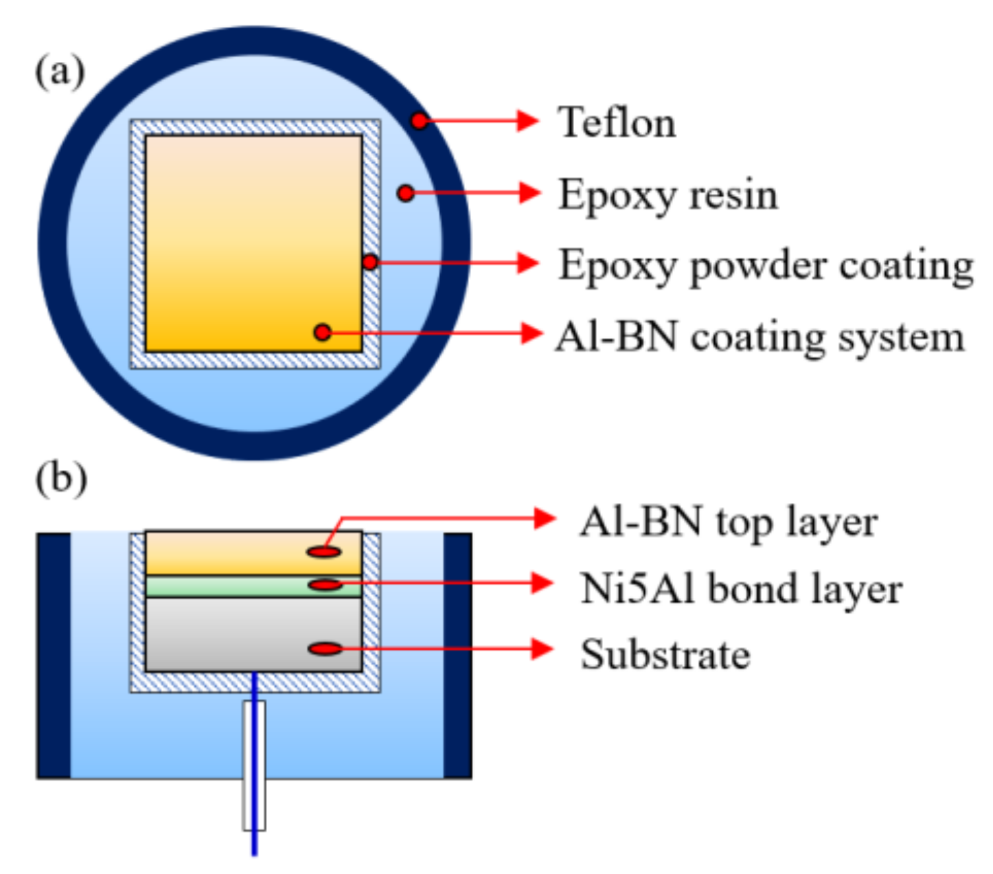
2.1. Materials

The Al–BN ACS in this study consists of an Al–BN top layer, a Ni5Al bond layer and a 0Cr17Ni4Cu4Nb substrate. Details of the manufacture process of Al–BN layer and Ni5Al layer were shown in our previous work [17]. Cross-sectional morphologies of the as-formed coating system in Figure 1 demonstrate the three parts of the sample, the top layer with thickness about 1 mm is Al-BN, and the bond layer with thickness about 50 μm is Ni5Al. Porosity of the Al–BN and Ni5Al layer are 28% and 2% respectively according to the previous research.
The porous Al-BN coating system samples for corrosion tests were prepared by a special process to make sure that the experimental results are correct. Firstly, the as-sprayed coating system was cut into small samples with 1 cm2 exposure area, connected to a wire on the uncoated surface of the substrate. Then, the connected specimens were embedded in epoxy resin with a pre-formed powder coating to prevent penetration of the uncured liquid epoxy resin into the porous layers. Schematic diagram of the sample is illustrated in Figure 2 by a top view and a cross-sectional view. Prior to the experiment, working surface of the as-prepared sample was wet-ground to 1000 grit SiC paper, fine polished using 0.5 μm diamond paste, cleaned ultrasonically with distilled water and acetone, and then dried in a compressed hot air flow.

2.2. Immersion and Electrochemical Tests

The corrosive medium was 5.0 wt % NaCl solution prepared from analytical grade reagents and distilled water. The tri-metallic Al–BN ACS were immersed in 5.0 wt % NaCl solution in contact with air at about 25 °C for various times at their free corrosion potential. Changes of the open circuit potential (OCP) for the Al–BN ACS during immersion were recorded.
Polarization curve and electrochemical impedance spectroscopy (EIS) measurements were performed by an autolab electrochemical measurement system (EG&G) using a three-electrode system, i.e., standard calomel electrode (SCE) as the reference electrode, platinum as the counter electrode, and samples shown in Figure 2 as the working electrode.
Anodic polarization curves of Al–BN ACS with different immersion times (1, 12, 24, 57, and 145 h) were scanned from the OCP to −0.56 V/SCE with a scan rate of 0.33 mV/s. Anodic polarization curve of the individual Al–BN layer was also obtained by the same method using a set-up in our previous work [17]. EIS measurements of Al–BN ACS were carried out at the OCP with the frequency range from 0.01 Hz to 100 kHz, and the perturbing AC amplitude was of 5 mV.
Electrochemical noise (EN) measurements of Al–BN ACS were performed using a set-up in EN mode. Two identical Al–BN ACS specimens were used as the working electrode and a SCE as the reference electrode, respectively. The electrochemical current noise was measured as the galvanic coupling current between two identical working electrodes (WEs) kept at the same potential. EN data was instantaneously recorded with time for 145 h. Each set of EN records contained 1024 data points and was recorded with a data-sampling interval of 0.25 s. The data were recorded immediately after the immersion of the working electrodes in the solution. The direct trend of electrochemical noise data was removed by using 5-order polynomial detrending method.

2.3. Corrosion Morphology Observation

The corrosion morphologies of the Al–BN ACS specimens with different immersion times, which were rinsed lightly with distilled water and dried spontaneously, were detected by Scanning Electron Microscopy (SEM) (XL30FEG, Wilmington, NC, USA). Corrosion products were not removed before the SEM observation.

3. Results

3.1. Polarization Curves

Figure 3 shows the initial anodic polarization curves of the Al–BN ACS and the separated Al–BN layer in 5.0 wt % NaCl solution respectively. The single Al-BN layer showed a stable passivation state due to the existence of a passive film. The pitting potential of Al–BN layer (Ep/Al–BN) is around ~0.78 V/SCE. However, there is no passivation behavior observed in the anodic curves of the coupled Al–BN ACS; a reasonable explanation to this phenomenon has been suggested in the previous work [17], which can be summarized as follows: Al–BN top layer was anodically polarized to its pitting region by the galvanic interaction among the coating system, resulting in a spontaneous pitting behavior of the samples. So as to estimate the repassivation ability of the Al matrix of Al–BN, we tested the cyclic polarization curve of pure Al (99.99%) in 5 wt % NaCl solution. The result is shown in Figure 4. Reverse polarization of Al produced a hysteresis loop that is characteristic of pitting corrosion. During the reverse scan, the reverse curve of Al did not cross the forward curve in the region of passivity, implying that Al did not show classical repassivation behavior, which reflected the characteristic of stable dissolution within the pit.
Figure 5 shows the changes of the anodic plots of Al–BN ACS with different immersion times. It is noteworthy that that real current density of Al–BN ACS and Al–BN layer are lower than the values from the polarization curves, because the porosity of the samples makes the real working surfaces larger than the apparent 1 cm2. From Figure 5, it was observed that the anodic curves of Al–BN coating system after 1 h and 12 h immersion exhibited no passivation behavior, and the apparent anodic current density increased sharply once the applied potential passed the Ecorr of the samples. This may be related to the phenomenon that value Ecorr of the coating system is positive to Ep/Al–BN of its Al–BN layer. However, samples after 24, 57 and 145 h immersion present passivation characteristics with a decreasing break potential and an increasing passive current as the immersion time extended, since Ecorr of the coating system drops into the passive region of Al–BN layer.

3.2. OCP

The time dependence of OCP values of the Al–BN ACS during immersion is shown in Figure 6. It is obvious that OCP values of the samples exhibited a three-stage characteristic with immersion time, including a slight decrease in value from −0.75 to −0.78 V/SCE during the first ~12 h immersion (stage I). Then the OCP experienced a rapid decay stage II until it reached −1.01 V/SCE after ~47 h immersion. At last, the OCP changed very little versus immersion time, reflecting a relatively stable stage III.
In fact, the OCP values in Figure 6 present the galvanic potential (Egal) of the coupled Al–BN ACS during immersion. Comparing the Egal values with the corrosion potential of the uncoupled Al–BN layer (EAl–BN) shown in Figure 3, it can be suspected that the Al–BN layer always acted as the anode during immersion since Egal is always positive to EAl–BN. Considering that the BN is an electrical insulator, there should be no galvanic corrosion between the Al matrix and the BN lubricant for the single Al–BN layer. Therefore, it is reasonable to conclude that anodic dissolution of the coupled Al–BN ACS almost occurs within the Al matrix of its Al–BN top layer. Furthermore, Egal values are compared with the pitting potential of the Al–BN layer (Ep/Al–BN) to evaluate the anodic dissolution of Al–BN at various immersion times. As shown in Figure 6, Egal values exhibit a slight decrease trend in pitting potential region that it positive to Ep/Al–BN in stage I (0–12 h), implying that the spontaneous pitting of the Al–BN layer lasts about 12 h in the initial immersion stage. In stage II (12–47 h), Egal values became negative to Ep/Al–BN and experienced a rapid decreasing process in the passive region (EAl–BN to Ep/Al–BN) of the Al-BN layer, which suggested that the spontaneous pitting of Al–BN top layer caused by the strong anodic polarization in stage I stopped. However, considering there is no repassivation behavior of Al as shown in Figure 4, stable dissolution within the existing pits on Al matrix of Al–BN layer would remain.

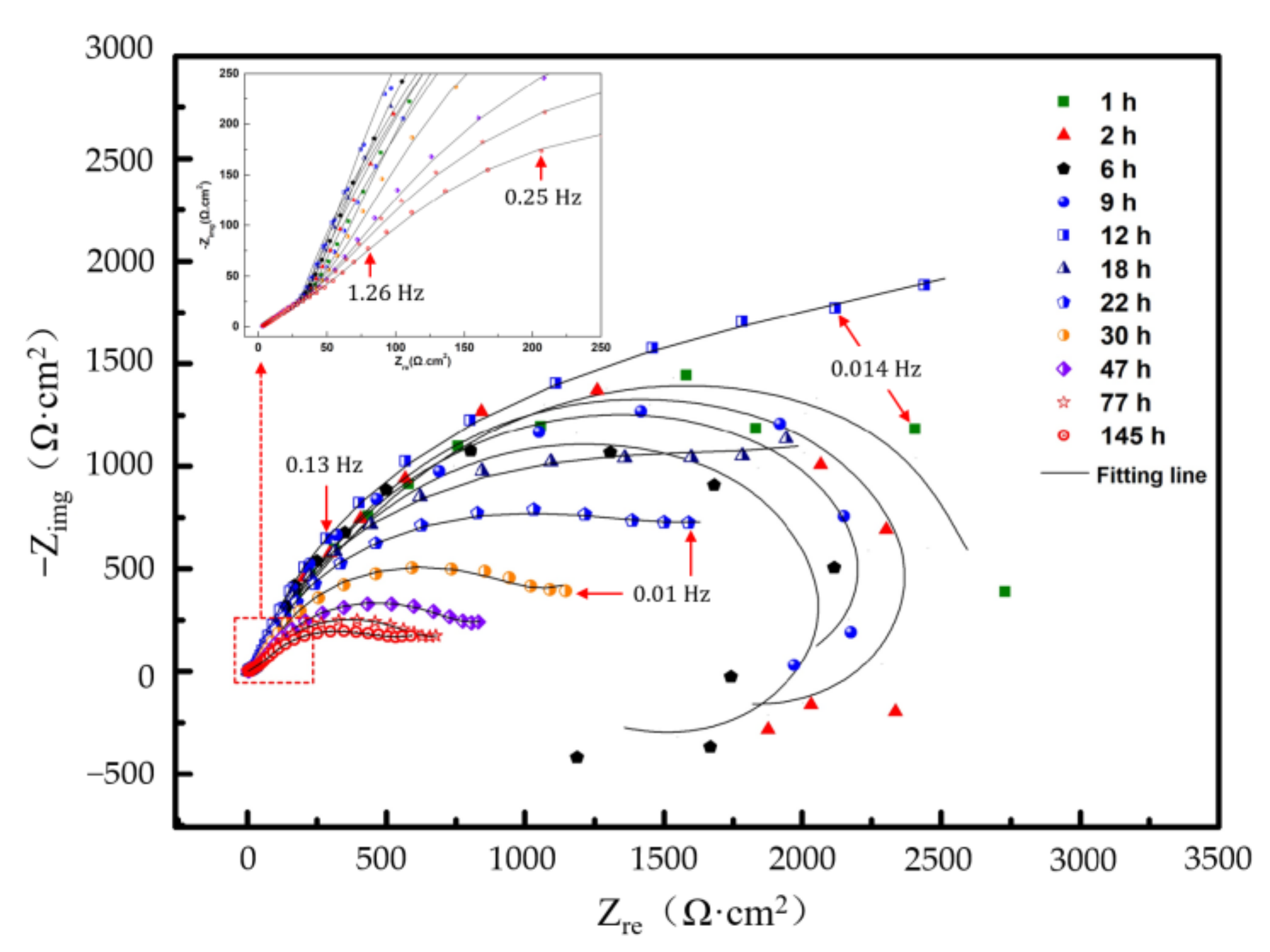
3.3. Electrochemical Impedance Spectra

EIS of the Al–BN ACS at Ecorr in 5.0 wt % NaCl solution with different immersion times are depicted in Figure 7. It is obvious that change of the impendence spectra of Al-BN coating system with immersion time also exhibited a three-stage process characteristic like OCP. In the first stage (0–12 h), the Nyquist plots exhibited three loops: an inconspicuous high frequency capacitive loop followed by an intermediate frequency capacitive loop, then a low frequency inductive loop. The inductive loop in EIS is often associated with the breakdown of protective film and the occurrence of pitting caused by anodic dissolution of metals. Thus, it is reasonable to assume the inductive feature of Al–BN coating system in stage I is associated with the spontaneous pitting process of Al–BN layer, which is consistent with OCP results of the first stage.
In the second stage (12–47 h), the Nyquist plots of the samples showed a curve with an inconspicuous diffusion tail at LF replacing the inductive loop in the first stage; this change in the plots implies that the galvanic corrosion process of Al–BN ACS possibly changes from charge transfer control to diffusion control. In addition, diameters of the capacitive loops decrease rapidly with the promotion of immersion time, indicating the arising of corrosion rate, or the decreasing of corrosion resistance with increasing of immersion time in the second stage.
In the third stage (47–145 h), patterns of the Nyquist plots did not change but a slight decrease of loops was obtained, which also agreed with the stable OCP values in the third stage shown in Figure 6.
For the purpose of estimating the galvanic corrosion rate in different stages quantitatively, the equivalent circuits Model A and Model B in Figure 8 are used to fit the EIS data containing inductive loop and diffusion loop, respectively. The elements in the circuits are defined as follows: Rs is solution resistance; Qhf is the high-frequency double-layer capacitance; Rhf is the high-frequency resistance representing the resistance of oxide film and corrosion products covered upon the pitting area of Al–BN layer; Rct is charge transfer resistance within the active pitting area at low frequency; Qlf is associated with the low frequency interface capacitance of the new interface originated from pitting, which is parallel to the Rct in low frequency range; L is the inductance at low frequency; and W is the Warburg element representing the diffusion process. Equivalent electrical circuit in Figure 8a was used to fit EIS results of stage I, while the Figure 8b was used for stage II and III. It is seen that the equivalent circuits fit the experimental data well in most of the frequency range, indicating that the equivalent circuits in Figure 8 are suitable. The parameters of fitted results are listed in Table 1.
Figure 9 shows the fitted Rhf and Rct as a function of immersion time. Variations of the Rhf and Rct are related with the corrosion products and the evolution of galvanic performance of the coupled Al–BN ACS. Compared to Rct, the Rhf values were relatively small and were even smaller than that of a common passive film of Al alloys [25,26]. Actually, Rhf of Al–BN ACS in Figure 8 represent the parallel resistance of oxide film on the uncorroded area and corrosion products on the breakdown site (or solution resistance in pits cavity) of the Al–BN layer; its value was determined by the smaller one in the parallel connection, i.e., determined by the resistance on pit initiation site. Therefore, if the Al–BN samples underwent pitting corrosion, the Rhf would be relatively small. Considering the conclusion drawn from the OCP, it is reasonable that the Rhf is relatively small and decreases with the pitting promoted during the spontaneous pitting corrosion in stage I. When the spontaneous pitting corrosion in stage I stops in stage II and III, values of Rhf increase with immersion time, implying the increase of corrosion products on pit site and the stabilization of the pitting area. The Rct after 12 h immersion exhibited a sustained decrease with immersion time, implying a lower resistance to active dissolution of the Al–BN ACS in stage II.

3.4. Electrochemical Noise

EN was carried out to instantaneously survey the dissolution rate of the Al–BN coating system in this work. EN data analysis in the time domain involves the calculation of the noise resistance, Rn. Figure 10 shows the inverse of Rn with immersion time, which also exhibits a three-stage feature as the OCP and EIS data. It is well known that 1/Rn is proportional to the corrosion rate. Thus, corrosion rate of the Al–BN coating system can be detected from the values of 1/Rn, which decreased in stage I, while they increased in stage II and were kept stable in stage III. The development of corrosion rate of Al–BN coating system determined by Rn is consistent with the EIS results.

3.5. Corrosion Morphology

Figure 11 shows the surface corrosion morphologies of the Al–BN ACS with 0, 8, 24, and 72 h immersion time, respectively, in 5 wt % NaCl solution at Ecorr. For the Al–BN ACS samples without immersion shown in Figure 11a, some macro-pores randomly distributed on the surface of Al–BN top layer can be observed, just like the cross-sectional view in Figure 1. Such kinds of pores could affect the corrosion resistance by providing preferential paths for corrosive species to penetrate. After 8 h of immersion, some scattered corrosion product was observed on the surface without blocking all the pores as shown in Figure 11b. With increasing of immersion time, the amount of corrosion product kept increasing and the macro-pores became progressively covered by deposition of the corrosion product. As illustrated in Figure 11c,d, the corrosion products became larger and spread to the areas after 24 h immersion, while they covered almost the pores of Al–BN layer after 72 h immersion.
Figure 12 further shows the in situ macroscopic morphology of the Al–BN ACS sample after 72 h immersion in 5.0 wt % NaCl solution, and the corrosion product after drying. It is observed that there are some H2 bubbles due to the negative difference effect (NDE) of Al and precipitate of Al(OH)3 on the surface during immersion [17]. When the sample was taken out from the solution and exposed in the air, the gel dried to white powders and covered most of the area of surface, like the morphologies shown in Figure 11.

4. Discussion

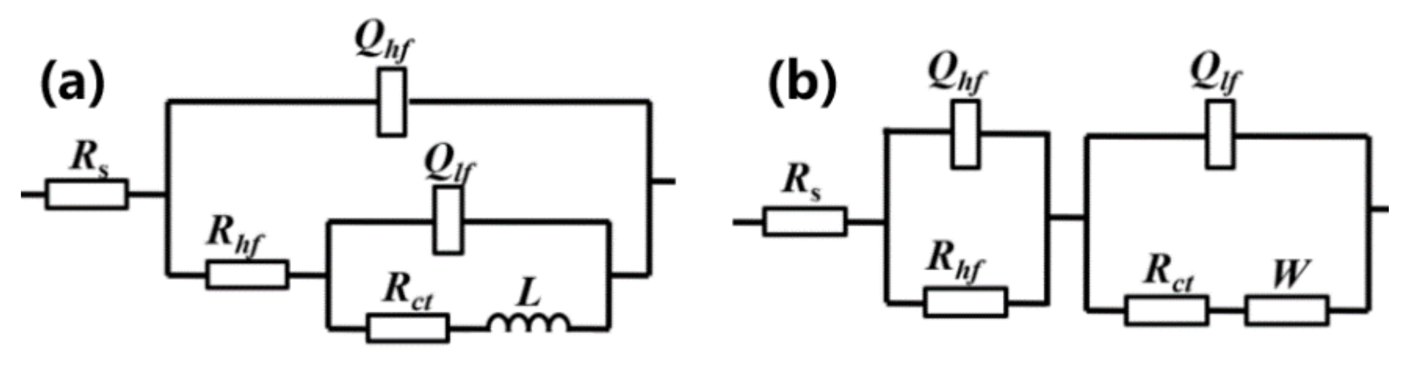
4.1. Corrosion Reactions and Relevant Models at Various Immersion Time

The possible corrosion reactions for the coupled Al–BN ACS during immersion and the relevant corrosion models are discussed in this part first.
As explained earlier, anodic dissolution of Al–BN ACS occurred mainly within the Al matrix of its Al–BN layer, therefore, the corrosion reactions of Al can be used to analyze the galvanic corrosion performance of Al–BN ACS. When immersed in NaCl solution, or anodically polarized to its active range, the passive film of Al could be ruptured due to pitting corrosion. According to the study from Li et al. [20], when a film-free surface of aluminum is exposed to an aqueous electrolyte, the ionization of atomic aluminum takes place by the following electrochemical reaction (1).
Al → Al3+ + 3e
As suggested by Hagyard et al. [27], O. Guseva et al. [19] and many others, the dissolved Al3+ is not stable in contract with water and reacts with H2O chemically to form aluminum-containing hydroxo complex ions (Equations (2)–(4)), which are also called the hydrolysis process of Al3+.
Al3+ + H2O → AlOH2+ + H+
AlOH2+ + H2O → Al(OH)2+ + H+
Al(OH)2+ + H2O → Al(OH)3(aq) + H+
Equation (1) is believed to be the main anodic reaction of Al during pitting occurring on the break down area of the passive film. However, the corresponding cathodic reaction depends on the solution. In neutral or basic solutions, the predominant cathodic reaction is the reduction of dissolved oxygen to hydroxyl ions according to Equation (5). For acidic solutions, the predominant cathodic reaction is the reduction of two hydrogen ions at a surface to form one molecule of hydrogen gas as shown in Equation (6).
O2 + 2H2O + 4e → 4OH
2H+ + 2e → H2
During the galvanic corrosion of Al–BN ACS, the cathodic reaction at the initial stage may cause the reduction of dissolved oxygen due to the solution being neutral. However, as the last immersion, the hydrolysis of anodic reaction products Al3+ produces H+ in the pits. Due to the consumption of O2 and accumulation of H+ in the pits, the predominant cathodic reaction may change to Equation (6).
According to Cao and Zhang [28], when the diffusion process was not involved in the Faradic process, the admittance Y (or impedance Z) for an electrode could be expressed as:
1 / Z = Y = j ω C dl + Y F
In the situation that there were two surface state variables, X1 and X2, controlling the electrode processes and were independent of each other, the admittance Y for the electrode could be expressed as:
Y = j ω C dl + 1 / R t + i = 1 2 I F / X i d X i   / d E   / 1 j ω / X i / X i  
According to Equation (8), there exists a capacitive loop in the high frequency range due to the double-layer capacitance, Cdl. and a capacitive loop in the intermediate or low frequency range caused by the faradic electrochemical reaction process of Xi when I F / X i d X i   / d E   < 0 . In contrast, an inductive loop appears when I F / X i   d X i   / d E   > 0 .
Li et al. [20] concluded that the cathodic hydrogen evolution reaction by Equation (6) on the non-oxide-protected region of Al could be promoted at high anodic potentials resulting from the local acidification caused by Al3+ hydrolysis by Equations (2)–(4), which was the explanation of the NDE of Al during corrosion. From the morphologies of corroded Al–BN ACS during immersion in Figure 12, there exists an obvious hydrogen evolution phenomenon during the anodic dissolution of Al–BN layer, indicating the existence of NDE during the galvanic corrosion of the Al–BN coating system. Since NDE of Al results from the combined effects of the local pH and the passive film’s breakdown area, therefore, it is reasonable to suspect that the anodic corrosion of Al–BN involves two independent surface state variables besides electrode potential E: the area fraction of the film-free area on the surface (θ), and the concentration of H+ in the pits (CH+). Let,
X1 = θ
X2 = CH+
In the corrosion process of Al–BN coating system, the first variable θ of the Al–BN layer increased with increasing andic potential E in the active range. That is, whenever EEp/Al–BN (θ ≠ 0), then:
d θ / d E   > 0
The current of the Faradic process is usually given by the difference between the anodic and cathodic current densities. For Al–BN ACS, the anodic and cathodic processes are combinations of the reactions occurring at the ruptured area of the passive film and on the undamaged oxide film. However, when θ ≠ 0, reactions occurring on the passive film have a relatively small magnitude compared with that at the film-free area, because these electrochemical reactions on a filmed surface are usually very difficult. Thus, the cathodic and anodic electrochemical processes related to the perfect surface film can usually be neglected. So that:
I F = θ × I a I c
where Ia presents the anodic current of the reaction as Equation (1), while Ic presents the cathodic current of reaction as Equation (5) or (6).
Considering the Al–BN layer was anodically polarized due to the galvanic interaction in stage I, the anodic current Ia should be larger than cathodic current Ic. Thus,
I F / θ = I a I c > 0
Combining Equation (11) with Equation (13), predicts,
I F / θ d θ / d E   > 0
That indicates that the Nyquist plot of the Al–BN sample should contain an inductive loop related to the surface stage variable θ when EEp/Al–BN.
For the second variable CH+, as can be seen from Equations (2)–(4), the hydrolysis of Al3+ produces H+, implying that CH+ should increase with the increasing concentration of Al3+ produced by the anodic dissolution of Al as Equation (1). So that CH+ should increase with increasing andic potential E. Therefore,
d C H + / d E   > 0
Taking the corresponding anodic and cathodic reaction into consideration, the Faradic current shown in Equation (12) could be further expressed as:
I F = θ × I 1 I 6 = θ × 3 F K 1 2 F K 6 C H +
Where I1 and I6 were the current densities associated with the reactions (1) and (6) respectively, while K1 and K6 are the forward reaction rate for reactions (1) and (6) respectively.
Equation (16) implied that:
I F / C H + = θ F K 6 < 0
So,
I F / C H + d C H + / d E   < 0
Equation (18) means that the H+ generated by Al3+ hydrolysis process would produce a capacitive loop in the EIS diagram when the Al–BN surface passive film is not perfect, that is, if θ ≠ 0. However, in the case of a perfect passive film (θ = 0), Equation (16) is no longer valid. No CH+ should be considered and IF has nothing to do with the CH+. Thus, there will be no capacitive loop caused by CH+ in the EIS plot.
The above analysis of AC impedance based on Cao’s theory can successfully explain the Nyquist plot of Figure 7. In stage I, the coupled Al–BN coating system electrode exhibited one capacitive loop and one inductive loop in the middle and low frequency ranges. The inductive loop is attributed to the partially passive film of the anodically polarized Al–BN layer resulting from the spontaneous pitting behavior in stage I (EEp/Al–BN), and the capacitive loop is related to the H+ ion concentration within the broken area. When the galvanic potential drops into the passive range of Al–BN layer (E < Ep/Al–BN) in stage II and III, corrosion behavior of the Al–BN layer gains a different characteristic as the change of the electrode potential. According to Figure 4, Al matrix of the Al–BN did not exhibit repassivation behavior in chloride solution, indicating that the pitting area of Al–BN layer generated in stage I did not repair when the potential dropped to the passive range. In other word, although the galvanic potential of the coating system lies in the passive range of Al–BN layer, the exiting pitting area would keep dissolute rather than repassivated. Therefore, it is reasonable to suspect θ did not change with the potential E in stage II and III, while corrosion within the pitting area generated in stage I went on. Thus, θ was no longer a surface state variable but CH+ remained during the corrosion stage II and III for the Al–BN coating system. Correspondingly, the Nyquist plots presented a capacitive loop and a diffusion tail in middle and low frequency range in stage II and III, presenting the variables CH+ and corrosion product respectively.

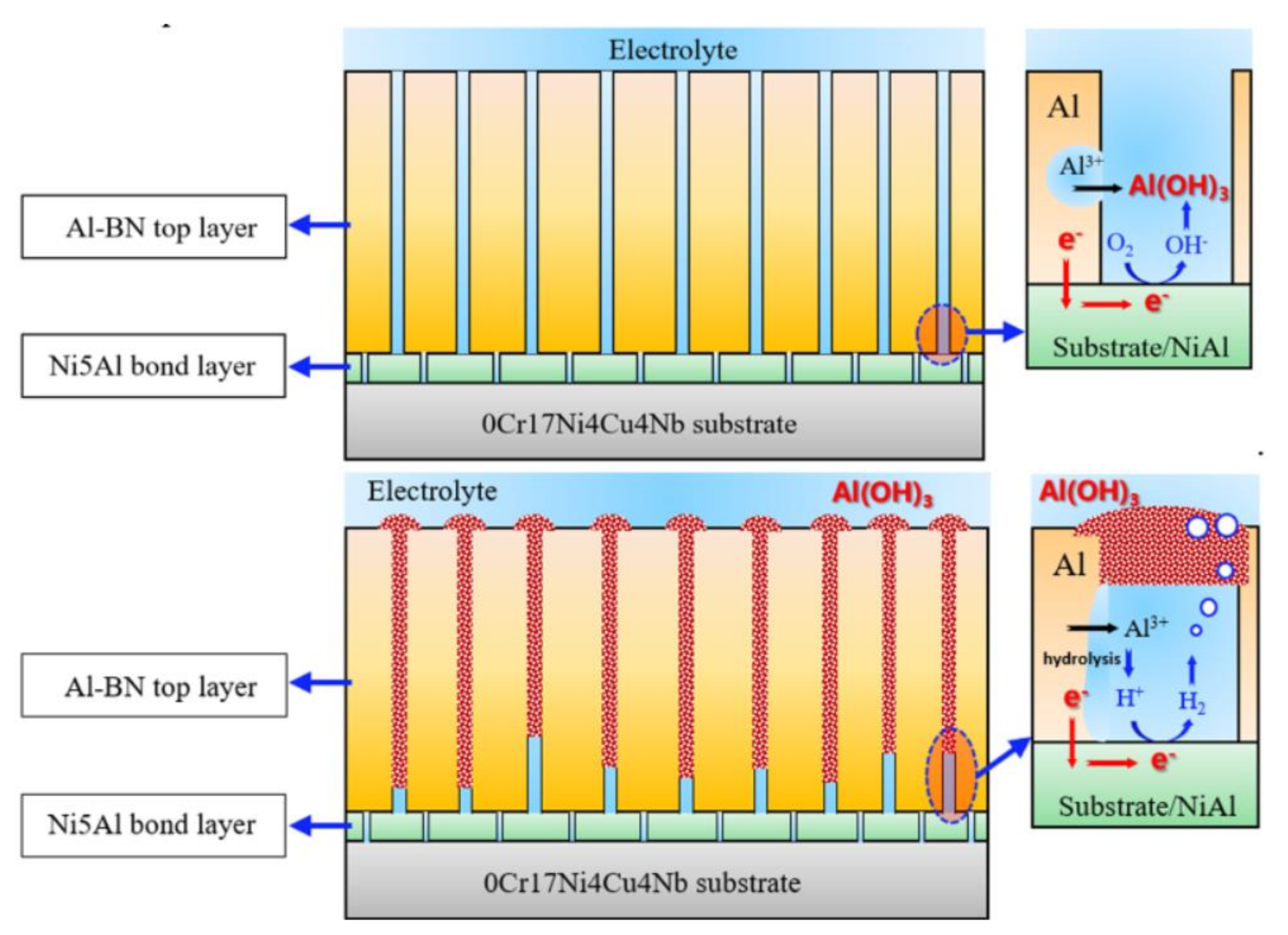
4.2. Effect of Products on Galvanic Corrosion

The electrochemical results mentioned above demonstrated that the Al–BN coating system suffered an active pitting with a decreasing rate during the initial immersion stage I, while the diffusion process was involved in corrosion stage II, accompanied with an increasing corrosion rate and a decreasing galvanic potential until a relatively stable status was reached in stage III. The corrosion products of Al–BN have significant effects on the long-term galvanic corrosion performance of Al–BN coating system, and the corresponding mechanism is further discussed in detail in this part.
It is already known that the strong anodic polarization of Al–BN layer yields spontaneous pitting on its Al matrix during the initial immersion stage and releases Al3+ ions as given by Equation (1). Then Al3+ ions hydrolyze to generate soluble H+ and Al(OH)3 by Equations (2)–(4) in the vicinity of the electrode surface and spread into the occluded electrolyte within the pores of the Al–BN layer. When the local concentration of the generated Al(OH)3 reaches oversaturation, precipitation occurs and generates insoluble corrosion product Al(OH)3 by Equation (19). Since the volume of the gelatinous Al(OH)3 is many times larger than the volume of the aluminum lost, the insoluble Al(OH)3 would spread to its surface along the pores of the Al–BN layer. As t the anodic dissolution product accumulates within the pores of the Al–BN layer, the steric hindrance effect of the precipitated Al(OH)3 has a significant effect on the mass transport of species, both the inward mass transport of O2 from outside of the dissolving area, and the outward mass transport of H+ ions generated inside the pores. Hence, with Al(OH)3 precipitate, the local environment inside the Al–BN layer should be even more occluded, resulting in localized acidification of the inner pores of the Al–BN layer, which would influence both the cathodic and anodic reactions for the coupled Al–BN ACS, and further, affect the long-term galvanic corrosion of the tested samples.
A l O H 3 aq   A l O H 3 s  
According to mixed potential theory, galvanic corrosion potential and corrosion rate of a couple are determined by conditions at the intersection of the total anodic and total cathodic polarization curves. Since the Al–BN layer is anodic relative to the Ni5Al layer and substrate of the coupled Al–BN ACS, the total anodic current density of the tri-metallic couple is essentially for Al dissolution on the Al–BN anode, since contributions from other oxidation reactions are negligible according to Cao’s theory. Similarly, the total cathodic current density for the tested couple is essentially that for oxygen consumption or hydrogen evolution reaction on Ni5Al/substrate cathode. Thus, the corrosion potential for the Al–BN ACS and the corresponding corrosion current for the Al–BN layer are given by the intersection of the polarization curves for reactions shown in Equations (1), (5) and (6). A simplified schematic diagram (Figure 13) was drawn to elucidate the features of long-term galvanic corrosion of Al–BN coating system mentioned above, which is particularly the reason why the galvanic potential shifted to more negative values with the increase in immersion time. For the anodic curve, the Al–BN layer shows a typical passivation behavior with a corrosion potential EAl–BN and pitting potential Ep/Al–BN as shown in Figure 3. For the cathodic curve, O2 reduction as Equation (5) should be the predominant reaction at the beginning of immersion since the initial electrolyte contains a certain concentration of dissolved O2 from the atmosphere. However, chemistry properties of the electrolyte within the inner pores of Al–BN samples would change as the immersion extended, which could be characterized by a decreasing of O2 and an increasing of H+. With the consumption of O2 and accumulation of H+ of the inner electrolyte, equilibrium potential of the cathodic reaction will shift toward more negative values according to the Nernst equation, and the corresponding cathodic curve would gradually move to the negative direction. This may be a possible reason to explain the decreasing of galvanic potential and corrosion rate in stage I. As it is shown in Figure 13, the intersection of cathodic curve and anodic curve in stage I lies in the pitting range of Al–BN (EgalEp/Al–BN), presenting the spontaneous pitting of Al–BN aroused by the anodic polarization in stage I. When the cathodic curve moves toward the negative direction, the intersection moves along the anodic curve within the pitting region, resulting in a decrease of galvanic corrosion potential and corrosion rate in stage I.
When the intersection of the cathodic curve and anodic curve moves into the passive region of the Al–BN layer as the decay of cathodic process, the Al–BN anode of the coating system will transform from active stage to passive stage, and the charge transfer controlled process in stage I may suddenly change into mass-transport controlled due to accumulation of corrosion products. For the anodic curve, the slope of the passivation region is bigger than that of the pitting region, which means that the same magnitude decay of the cathodic plot will result in a larger decrease of galvanic potential in the passivation region than that in the pitting region. This is a possible explanation for the phenomenon that the galvanic potential of stage II had a higher decreasing rate than that of stage I.
However, the increasing corrosion rate in stage II may be related to the localized acidification inside the corroding volume of the Al–BN layer. This idea is supported by the anodic polarization curves of Al–BN ACS with different immersion times shown in Figure 5. As the accumulation of corrosion products of Al–BN, the hydrolysis of the Al3+ from the anode dissolution increases the concentration of H+ in the pore, while the electromigration process of the ions in the solution also increases the concentration of Cl- in the pore. Such kind of acidification develops the occluded electrolyte into more severe conditions for localized corrosion; the passive current density of Al–BN layer increases and pitting potential deceases with immersion time, indicating that anodic dissolution of Al–BN layer is accelerated as the electrolyte becomes more aggressive. Thus, the localized acidification inside the corroding volume resulting from the blocking effects of corrosion products could explain the increasing corrosion rate of the Al–BN coating system during stage II.
Based on the analysis mentioned above, a schematic presentation for the long-term corrosion process of the coupled Al–BN ACS is shown in Figure 14, and the corresponding mechanisms are described as follows. At the beginning of immersion, the Al–BN layer of the coating system exhibited active dissolution due to the galvanic interaction anodically shifted its potential to the pitting region. The anodic dissolution of Al–BN generated Al3+ in the pits, and the hydrolysis of Al3+ further produced H+ and Al(OH)3 precipitate. As the immersion went on, both galvanic potential and galvanic corrosion rate exhibited a decreasing trend, which could be related to the decay of cathodic O2 reduction reaction since the transport process of O2 was blocked by the corrosion products. Once galvanic potential of the coating system descended to the passive region of Al–BN layer, the spontaneous pitting should not expand any longer, but dissolution within the existed broken area would remain because the Al matrix of the Al–BN layer did not show repassivation behavior. In addition, with the buildup of Al(OH)3 products in the pores of Al–BN, localized acidification occurred and promoted the corrosion rate of Al–BN.

5. Conclusions

  • The galvanic corrosion of the Al–BN ACS could be distinguished into three stages during long-term immersion, including a spontaneous pitting stage I with decreasing rate, a developing corrosion stage II with increasing rate, and a final steady stage III.
  • The steric hindrance effect of a precipitated corrosion product Al(OH)3 may be the most important corrosion rate-controlling mechanism for the tri-metallic coupled Al–BN ACS for long-term immersion, including precipitation of Al(OH)3 pores restricting O2 transport to the cathode and localized acidification inside the occluded pores.

Author Contributions

Conceptualization, B.L. and G.M.; methodology, M.P. and L.L.; validation, W.Z. and S.H.; formal analysis, M.P. and L.L.; investigation, W.Z.; resources, S.H.; data curation, B.L.; writing—original draft preparation, B.L.; writing—review and editing, G.M.; visualization, W.Z.; supervision, G.M.; project administration, B.L.; funding acquisition, B.L. All authors have read and agreed to the published version of the manuscript.

Funding

This research was funded by the Fundamental Research Funds for the Central Universities (grant number 20lgpy75).

Institutional Review Board Statement

Not applicable.

Informed Consent Statement

Not applicable.

Data Availability Statement

Data sharing is not applicable to this article.

Conflicts of Interest

The authors declare no conflict of interest.

References

  1. Dorfman, M.; Erning, U.; Mallon, J. Gas turbines use ‘abradable’ coatings for clearance-control seals. Seal. Tech. 2002, 2002, 7–8. [Google Scholar] [CrossRef]
  2. Rajendran, R. Gas turbine coatings—An overview. Eng. Fail. Anal. 2012, 26, 355–369. [Google Scholar] [CrossRef]
  3. Wang, H. Criteria for analysis of abradable coatings. Surf. Coat. Technol. 1996, 79, 71–75. [Google Scholar] [CrossRef]
  4. Johnston, R.; Evans, W. Freestanding abradable coating manufacture and tensile test development. Surf. Coat. Technol. 2007, 202, 725–729. [Google Scholar] [CrossRef]
  5. Tong, Y.-Q.; Shi, Q.-S.; Liu, M.-J.; Li, G.-R.; Li, C.-J.; Yang, G.-J. Lightweight epoxy-based abradable seal coating with high bonding strength. J. Mater. Sci. Technol. 2021, 69, 129–137. [Google Scholar] [CrossRef]
  6. Tang, N.; Zhang, B.; Lord, C.; Marshall, M. Identification of blade operational mode shapes during wear of abradable coating. J. Sound Vib. 2020, 472, 115204. [Google Scholar] [CrossRef]
  7. Ma, X.; Matthews, A. Evaluation of abradable seal coating mechanical properties. Wear 2009, 267, 1501–1510. [Google Scholar] [CrossRef] [Green Version]
  8. Zhang, B.; Marshall, M. Investigating material removal mechanism of Al-Si base abradable coating in labyrinth seal system. Wear 2019, 239–249. [Google Scholar] [CrossRef] [Green Version]
  9. Xue, W.; Gao, S.; Duan, D.; Zhang, J.; Liu, Y.; Li, S. Effects of blade material characteristics on the high-speed rubbing behavior between Al-hBN abradable seal coatings and blades. Wear 2018, 410–411, 25–33. [Google Scholar] [CrossRef]
  10. Nyssen, F.; Batailly, A. Sensitivity Analysis of Rotor/Stator Interactions Accounting for Wear and Thermal Effects within Low- and High-Pressure Compressor Stages. Coatings 2020, 10, 74. [Google Scholar] [CrossRef] [Green Version]
  11. Song, G.-L. Potential and current distributions of one-dimensional galvanic corrosion systems. Corros. Sci. 2010, 52, 455–480. [Google Scholar] [CrossRef]
  12. Qiu, J.; Wu, A.; Li, Y.; Xu, Y.; Scarlat, R.; Macdonald, D.D. Galvanic corrosion of Type 316L stainless steel and Graphite in molten fluoride salt. Corros. Sci. 2020, 170, 108677. [Google Scholar] [CrossRef]
  13. Chen, Y.; Wang, Y.; Zhou, L.; Meng, G.; Liu, B.; Wang, J.; Shao, Y.; Jiang, J. Macro-galvanic effect and its influence on corrosion behaviors of friction stir welding joint of 7050-T76 Al alloy. Corros. Sci. 2020, 164, 108360. [Google Scholar] [CrossRef]
  14. Zhang, F.; Lan, H.; Huang, C.; Zhou, Y.; Du, L.; Zhang, W. Corrosion Resistance of Ti3Al/BN Abradable Seal Coating. Acta Met. Sin. 2014, 27, 1114–1121. [Google Scholar] [CrossRef] [Green Version]
  15. Xu, C.; Du, L.; Yang, B.; Zhang, W. Study on salt spray corrosion of Ni–graphite abradable coating with 80Ni20Al and 96NiCr–4Al as bonding layers. Surf. Coat. Technol. 2011, 205, 4154–4161. [Google Scholar] [CrossRef]
  16. Zhang, F.; Xu, C.; Lan, H.; Huang, C.; Zhou, Y.; Du, L.; Zhang, W.-G. Corrosion Behavior of an Abradable Seal Coating System. J. Therm. Spray Technol. 2014, 23, 1019–1028. [Google Scholar] [CrossRef]
  17. Lei, B.; Li, M.; Zhao, Z.; Wang, L.; Li, Y.; Wang, F. Corrosion mechanism of an Al–BN abradable seal coating system in chloride solution. Corros. Sci. 2014, 79, 198–205. [Google Scholar] [CrossRef]
  18. Hebert, K.R.; Zhang, G.; Ho, K.-M.; Wang, C.-Z. Modeling electrochemical and metal-phase processes during alkaline aluminum corrosion. Electrochim. Acta 2011, 58, 203–208. [Google Scholar] [CrossRef]
  19. Guseva, O.; Derose, J.; Schmutz, P. Modelling the early stage time dependence of localised corrosion in aluminium alloys. Electrochim. Acta 2013, 88, 821–831. [Google Scholar] [CrossRef]
  20. Yu, Y.; Li, Y. New insight into the negative difference effect in aluminium corrosion using in-situ electrochemical ICP-OES. Corros. Sci. 2020, 168, 108568. [Google Scholar] [CrossRef]
  21. Håkansson, E.; Hoffman, J.; Predecki, P.; Kumosa, M. The role of corrosion product deposition in galvanic corrosion of alumi-num/carbon systems. Corros. Sci. 2017, 114, 10–16. [Google Scholar] [CrossRef]
  22. Yin, L.; Jin, Y.; Leygraf, C.; Pan, J. A FEM model for investigation of micro-galvanic corrosion of Al alloys and effects of deposition of corrosion products. Electrochim. Acta 2016, 192, 310–318. [Google Scholar] [CrossRef]
  23. Romaine, A.; Jeannin, M.; Sabot, R.; Necib, S.; Refait, P. Corrosion processes of carbon steel in argillite: Galvanic effects associated with the heterogeneity of the corrosion product layer. Electrochim. Acta 2015, 182, 1019–1028. [Google Scholar] [CrossRef]
  24. Robineau, M.; Romaine, A.; Sabot, R.; Jeannin, M.; Deydier, V.; Necib, S.; Refait, P. Galvanic corrosion of carbon steel in anoxic conditions at 80 °C associated with a heterogeneous magnetite (Fe3O4)/mackinawite (FeS) layer. Electrochim. Acta 2017, 255, 274–285. [Google Scholar] [CrossRef]
  25. Martin, F.J.; Cheek, G.T.; O’Grady, W.E.; Natishan, P.M. Impedance studies of the passive film on aluminium. Corros. Sci. 2005, 47, 3187–3201. [Google Scholar] [CrossRef]
  26. Ryl, J.; Wysocka, J.; Jarzynka, M.; Zielinski, A.; Orlikowski, J.; Darowicki, K. Effect of native air-formed oxidation on the corrosion behavior of AA 7075 aluminum alloys. Corros. Sci. 2014, 87, 150–155. [Google Scholar] [CrossRef]
  27. Hagyard, T.; Williams, J.R. Potential of aluminum in aqueous chloride solutions. Faraday Soc. 1961, 57, 2288–2294. [Google Scholar] [CrossRef]
  28. Cao, C. On the impendence plane displays for irreversible electrode reactions based on the stability condition of the steady-state. Electrochim. Acta 1990, 37, 837–844. [Google Scholar] [CrossRef]
Figure 1. Cross-sectional morphologies of the prepared Al–BN ACS.
Coatings 11 00009 g001
Figure 2. Schematic diagram of the Al–BN ACS electrode; top view (a) and cross-section (b).
Coatings 11 00009 g002
Figure 3. The initial anodic polarization curves of Al–BN ACS and separated Al–BN layer in 5.0 wt % NaCl solution.
Coatings 11 00009 g003
Figure 4. Cyclic polarization curve of pure Al (99.99%) in 5 wt % NaCl solution.
Coatings 11 00009 g004
Figure 5. Anodic plots of Al–BN ACS with different immersion times in 5.0 wt % NaCl solution.
Coatings 11 00009 g005
Figure 6. Change of OCP of the Al–BN ACS with immersion time in 5.0 wt % NaCl solution.
Coatings 11 00009 g006
Figure 7. Nyquist plots of the Al–BN ACS with different immersion times.
Coatings 11 00009 g007
Figure 8. Equivalent circuits for Al–BN ACS with different exposure times: (a) Model A, (b) Model B.
Coatings 11 00009 g008
Figure 9. Fitted values of Rhf and Rct of the Al–BN ACS in equivalent circuits.
Coatings 11 00009 g009
Figure 10. The inverse of noise resistance (1/Rn) of Al–BN ACS.
Coatings 11 00009 g010
Figure 11. Corrosion morphologies of Al–BN ACS after immersion time in 5.0 wt % NaCl solution for (a) 0, (b) 8, (c) 24, and (d) 72 h.
Coatings 11 00009 g011
Figure 12. The in-situ macro surface morphologies of Al–BN ACS with 72 h immersion in 5.0 wt % NaCl solution and the as-corroded sample after drying.
Coatings 11 00009 g012
Figure 13. Schematic diagram about changes of the galvanic potential based on mixed potential theory.
Coatings 11 00009 g013
Figure 14. Schematic presentation of the galvanic corrosion development of the Al–BN ACS.
Coatings 11 00009 g014
Table 1. The fitting results of the EIS parameters obtained on the Al–BN coating system.
TimeRs
(Ω × cm2)
Qhf
(F/cm2)
n1Rhf
(Ω × cm2)
Qlf
(F/cm2)
n2Rct
(Ω× cm2)
L
(H × cm2)
W
(Ω × cm2)
1 h3.199.20 × 10−40.60394.132.63 × 10−40.971331517,800-
2 h3.198.40 × 10−40.62373.013.54 × 10−40.942169710,750-
6 h3.121.03 × 10−30.60871.363.42 × 10−40.99411749011-
9 h3.161.0 × 10−30.61559.333.95 × 10−40.975212513,220-
12 h2.812.54 × 10−30.50451.151.17 × 10−30.9232613-1.99 × 10⁻³
18 h2.842.81 × 10−30.49665.111.23 × 10−30.9411793-2.92 × 10⁻³
22 h2.942.32 × 10−30.51888.421.32 × 10−30.9611378-4.72 × 10⁻³
30 h2.852.4 × 10−30.516102.61.46 × 10−30.967918.6-9.71 × 10⁻³
47 h2.962.64 × 10−30.498139.41.97 × 10−30.937589.3-11.19 × 10⁻³
77 h2.783.04 × 10−30.471197.32.02 × 10−30.963427.5-22.35 × 10⁻³
145 h3.033.25 × 10−30.443221.62.92 × 10−30.999409.9-25.78 × 10⁻³
Publisher’s Note: MDPI stays neutral with regard to jurisdictional claims in published maps and institutional affiliations.

