Abstract
The friction and wear characteristics of spike-tooth material (65Mn steel) of Spike-Tooth Harrow in a two-stage peanut harvester were studied in this paper. The friction and wear tests of pin and disc on 65 manganese steel were carried out on the tribometer, then the wear loss and the friction coefficient were studied. The wear loss of the pin was acquired by calculating the mass of the pin before and after the experiment using an electronic balance. According to the actual working environment of peanut spring-finger, four variable parameters are set up: load, speed, soil moisture and soil type. The friction and wear characteristics of pins were studied under different loads, speeds and different soil environments. After wearing, the worn surface of the material was observed by scanning microscope and the wear mechanism was studied. The experimental results show that the wear of the pin increases with the increase of load and decreases with the increase of rotational speed in the same rotation number. Especially in the case of the sandy soil with 20% in moisture, a maximum wear loss of the pin is achieved.
1. Introduction
Peanut is a significant oil and food plant in the world. The annual production of peanuts is about 46 million tons. The United States and China together grow more peanuts than any other country in the world, with China leading the world in the area and production of peanuts. In the past, the harvest of peanuts was mainly based on artificial harvests. Their primary production includes pulling out, sun drying and threshing. With the continuous advancement of science and technology, the development of peanut harvesters has also been rapid in recent years [,,,].
Peanut harvesters are mainly divided into two types: peanut combine harvesters and peanut two-stage harvesters. Peanut combine harvesters can complete a series of operations such as digging, conveying, clearing the soil and picking peanuts at the same time. Due to the moist climate in southern areas of China, it will cause rot and mildew if peanuts cannot be harvested in time. So the peanut combine harvester is suitable for the southern areas of China. A two-stage peanut harvester has two processes when harvesting peanuts. Firstly, peanuts are excavated from the ground and dried orderly on the ground. Secondly, it picks up the dried peanuts and transports them to the soil cleaning device. The vines can continue to provide nutrients for peanuts during the drying process of peanuts. Due to the dry climate in northern areas of China, two-stage peanut harvesters are often used to harvest peanuts [].
Scholars have been studying and developing peanut harvesters in many developed countries. Both LP-2 peanut combine harvesters from the United States and PH-2 peanut harvesters from the Netherlands are the typical representatives []. Although it is behind the development of peanut harvesters in China, Chinese scholars have done a lot of research on peanut harvesters. Chai et al. developed the 4 SHWZ-18004 peanut harvester, which mainly consists of the chassis, the transmission system, the soil cleaning device, the peanut paving device and the transporting collection device, and so on. The machine has designed the arrow digging shovel, which reduces the digging resistance and improves the soil breaking effect. The combined technology of digging and shaking is used to achieve a wide harvest of peanuts and improve work efficiency. Field experiments show that the machine is flexible, simple, smooth and stable []. Hu et al. designed a 4HL peanut harvester and studied its performance in the field. This peanut harvester is a large-scale equipment, which can be used for digging, cleaning, transporting and picking peanuts at one time. The equipment mainly includes a chassis, a transmission system and operation components. The test and application show that the machine has a stable performance and a smooth operation. However, the device is suitable for areas where peanuts are grown on a large scale, and it is hard to play its full role in countries where peanuts are grown on a small scale [].
Xu analyzed the ideal position and swing rules of the pickup component according to the typical peanut type and planting characteristics in China. Finally, a new spring-finger was designed and its picking performance was analyzed experimentally. The results showed that it had the highest collection rate and the lowest loss rate when the pods were in front of peanut []. Tseng and Lin studied the lifespan of the transmission shafts from the view of microstructure. They find that the three transmission shafts made by different hot rolling and heat treatment processes have a great difference in lifespan varied under the same using condition. They get a better lifespan by studying the facts of the fracture mode of the transmission shaft, the best hot rolling condition and the heat treatment condition [].
Manganese steel is one of the most commonly used ferroalloys for resisting wear. Yazici studied the tribological characteristics of the material (30MnB5 steel) used in moldboard plowshares. The effect of different heat treatment methods on wear loss was studied. After field tests, it is concluded that tempering treatment of martensite is a significant improvement in wear resistance of the plowshares [,,]. The research on the peanut harvester by scholars outlined above was performed. Most scholars mainly study the structure design and performance of peanut harvesters. So far, there are few people who have studied the peanut harvester in the aspect of friction and wear characteristics. Based on the two-stage peanut harvester, this paper studies the tribological characteristics of the material (65Mn steel) used in the spring-finger of the peanut pickup device. Wang et al. studied the corrosion behavior of 65Mn steel after boronizing treatment in hydrochloric solution and the weak acidic that fertilizer-containing soil. They found that the corrosion resistance of 65Mn steel after boronizing treatment in the two acid mediums remarkably improved. Dong et al. reported that successful surface modification took place via electrical discharging with a silicon electrode. The experimental results elucidated that the hardness as well as the wear and corrosion resistance of 65Mn steel was obviously improved by fabricating an amorphous nanocrystalline alloy layer in a controllable way on the surface of 65Mn steel. Zhang et al. treated 65Mn steel with Quench-Polish-Quench (QPQ) and studied its wear properties by experiments. However, in this experiment, sandpaper was used to cause abrasive wear of 65Mn steel, the conditions of which were not the same as the actual working conditions of the peanut spring-finger [,,].
Ucgul et al. established a contact model, which can predict tillage draft and vertical tillage forces under different speeds and different soil. The function of the spring-finger is to pick up the peanut lying on the ground for the next treatment []. In this process, the soil will contact with the peanut spring-finger and cause it to wear out. In addition, the peanuts are suitable for planting in slightly acidic soil, which will corrode the spring-finger to some extent, aggravating their wear. The impact strength of spring-finger will be reduced when it is worn to a certain extent, which may lead to the fracture occurrence of the spring-finger. In this paper, different loads, speeds, soil types and soil moistures are set as experimental parameters to better simulate the real working environment of the peanut pickup device. The wear extent of the pin was acquired by calculating the quality of the pin before and after the experiment using FA2204C electronic balance (Nanbei Instrument Equipment Co. Ltd, Zhengzhou, China). After wearing, the worn surface of the material was observed by scanning with a VHX-5000 microscope (KEYENCE, Osaka, Japan) and the wear mechanism was studied. In this paper, the friction and wear characteristics of spring-finger materials are studied, which can provide a reference for the designers of peanut harvesters and improve the working life of peanut harvesters.
2. Experimental Set-Up
The friction and wear experiments were carried out on a MMW-1 vertical omnipotence friction and wear testing machine (Shijin Group Co. Ltd, Jinan, China) without lubrication at 20–28 °C. A pin-on-disc tribometer was used to simulate the sliding part of the spring-finger contact with the soil. This tribometer is divided into the working part and the control part: The working part includes a motor, a fixture and loading system; the control section can be used to control load, time, speed, revolution, and maximum friction torque in the experiment.
Figure 1 shows schematic drawing of the pin-on-disc wear test. The container and disk are fixed. The motor drives the rotation of the pin, which slides on the surface of the disk. The disc is located in a steel vessel and loaded by the loading system. The contact surface is immersed in the soil and there is relative sliding between the pin and disc. The friction coefficient is displayed in the computer, which is connected to the machine through sensors. Figure 2 shows the actual situation of the friction and wear experiment between the pin and the disk, which includes soil, rhizomes of peanut, and small stones. The proportion of them is 11:7:2.
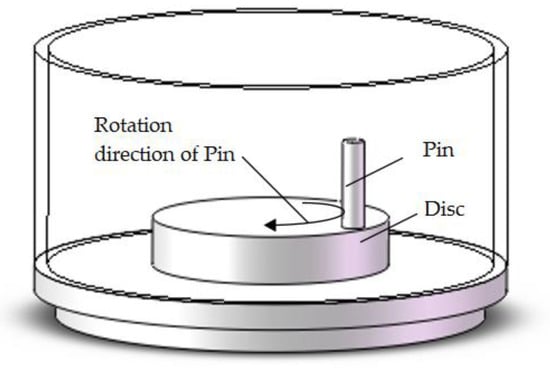
Figure 1.
The schematic drawing of the pin-on-disc.
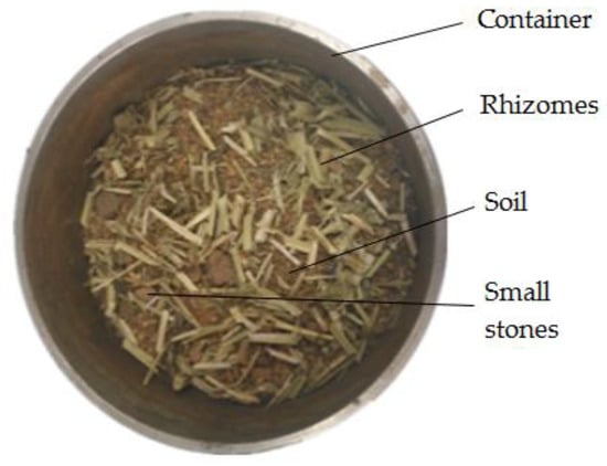
Figure 2.
The actual situation of the wear test.
The pin specimens were manufactured using same materials as the peanut spring-finger: 65Mn steel. The pin and disc geometry are shown in Figure 3. The material of the disc is 45 steel. The surface roughness of samples is Ra6.3. The pin had a diameter of 5 mm and a length of 20 mm, and the diameter and the thickness of the disc were 55 mm and 11 mm, respectively. The pin and disk surfaces were cleaned using acetone and alcohol to avoid non-desirable films such as grease on the surface.
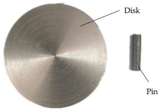
Figure 3.
The pin and disk.
The rhizomes of peanut are easily entangled with soil debris when the peanut spring-finger was working. The tensile strength of rhizomes of peanut is about 8 N. The actual speed range of the spring-finger is 0.8–1.8 m/s. In order to simulate the working conditions of the peanut spring-finger as much as possible, the wear tests were carried out under loads of 2, 5 and 8 N; sliding velocities of 300 r/min (0.82 m/s), 450 r/min (1.22 m/s) and 600 r/min (1.63 m/s); soil types of sandy soil, loam and clay; and soil moisture (the percentage of water mass in total mass) of 0, 10% and 20% [,]. The tests were maintained until the revolutions of 12,250 (the peanut harvester worked the distance of 3000 m). Specific experimental parameters are given in Table 1. The wear tribometer recorded continuously the friction coefficient, normal load and revolutions. The wear loss of the pin was acquired by calculating the mass before and after the experiment using an electronic balance. In order to minimize data scattering, each test was repeated three times. The friction coefficient and wear loss reported are average values. Soil would be changed after each test to ensure the accuracy of the experiment.

Table 1.
Experimental conditions.
3. Results and Discussion
3.1. Wear Loss and Friction Coefficient
3.1.1. Effect of Load
Wear refers to the loss of material on the contact surfaces. There are four common wear mechanisms: abrasive wear, adhesive wear, oxidation wear and surface fatigue []. Figure 4 shows the variation of wear loss and the friction coefficient as a function of the sliding distance under different loads for pin and disc. The experimental conditions were a soil type of loam, soil moisture of 0 and rotating speed of 300 r/min. Figure 4a shows that the wear loss increased linearly with the sliding distance after a short monotonic rise at the load of 5 and 8 N. However, the wear loss can be divided into three states with the increase of sliding distance at the load of 2 N: (i) increased, (ii) stabilized and (iii) increased rapidly. The wear procedure can be resolved into three periods: initial wearing, normal wearing and fatigue wearing. It is very consistent with this phenomenon when the load is 2 N. This phenomenon is not obvious at the load of 5 and 8 N because the load is too large. It is known that the friction is proportional to positive pressure, so the wear loss increases with the increase in the load. Figure 4b shows that the friction coefficient increased first and then stabilized. Figure 4b shows that the friction coefficient is greater than 1, because the experiment was carried out between metal and metal without lubrication. The sample material is hard, and there will be great resistance and fluctuation between contact surfaces without lubrication. The decreasing trend in the friction coefficient with the increase of load might be due to the large loads reducing the fluctuation between contact surfaces.
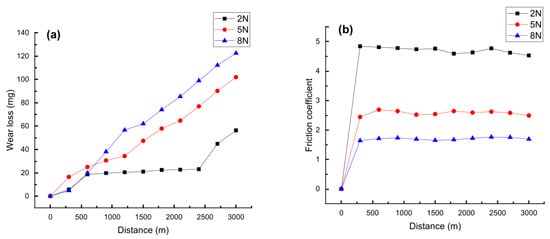
Figure 4.
Variations of wear loss and friction coefficient with the sliding distance under different loads (300 r/min, loam, moisture 0): (a) wear loss and (b) friction coefficient.
3.1.2. Effect of Speed
Figure 5 shows the variation of the wear loss and friction coefficients of various speeds under the same conditions, which were a normal load of 5 N, soil type of loam and soil moisture of 0. Figure 5a shows that the wear loss increased linearly with the sliding distance and the wear loss increased with the decrease in speed. Because the experimental distance is constant, the faster the speed is, the shorter the experimental time is. Therefore, the experimental time and the contact time of the wear test is longest when the rotational speed is 300 r/min and shortest when the rotational speed is 600 r/min. As can be seen in Figure 5a, the wear loss at 300 r/min is nearly worth two times at 600 r/min. Therefore, the conclusion can be obtained from Figure 5a that the wear loss is inversely proportional to the speed at the same sliding distance of 3000 m. Figure 5b shows that the friction coefficient of the three speeds is not very different, and fluctuates around 2.5. This indicates that the change of speed has little effect on the friction coefficient.
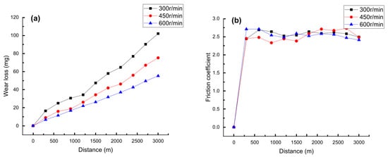
Figure 5.
Variations of wear loss and friction coefficient with the sliding distance under different speeds (5 N, loam, moisture 0): (a) wear loss and (b) friction coefficient.
3.1.3. Effect of Moisture and Soil
The average wear loss and friction coefficient under different soil types and soil moisture for pin and disc is shown in Figure 6. The experiment was performed under a rotating speed of 450 r/min and a normal load of 5 N. As shown in Figure 6a, the average wear loss increases with the increase of moisture under the different soil types and the wear loss at a moisture of 0 is much less than that at moisture 10% and 20%. The increase in soil moisture indicates an increase in the water content of the soil, which caused the emergence of a more complex wear mechanism. Figure 6a shows that the average wear loss in sandy soil is much greater than that in loam and clay. The reason for this result is that the sandy soil contains a large amount of sand particle, which causes severe abrasive wear between the disc and the pin. Figure 6b shows the average friction coefficient under the different soil conditions. It is obvious that the coefficient of friction is not much different between the moisture of 0 and moisture of 10%. However, the friction coefficient is significantly lower when the soil moisture is 20%. The reason for this phenomenon is that the soil contains more water, which acts as a lubricant between wear contact surfaces of pin and disc. As the sandy soil contains a large number of hard sand particles, the sharp vibration at the contact surface between the pin and the disc caused the increase in the friction coefficient.
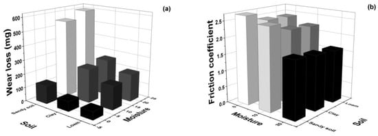
Figure 6.
Variations of wear loss and friction coefficient with the sliding distance under different moisture and soils (450 r/min, 5 N): (a) wear loss and (b) friction coefficient.
3.2. Wear Surface and Damage Mechanism
Figure 7 shows the micro morphologies of worn surfaces of the pin at different loads. The experiment was performed under a soil type of loam, a rotating speed of 300 r/min and moisture of 0. The presence of the soil means much more complicated three-body wear mechanisms exist in the wear surface. Obviously, typical abrasive wear, adhesive wear and oxidative wear characteristics were observed. The wear surface between the pin and disc contains soil (containing some small sand) as the intermediate medium, so the micro morphologies of worn surfaces of the pin show obvious mark of abrasive wear (Figure 7a–c). Figure 7d shows deep grooves that provide evidence of heavy abrasive wear. It can be seen from Figure 4a that the surface of the pin, which was tested under the load of 2 N, has reached a stage of severe wear, which is consistent with the situation shown in Figure 7d. Figure 7e indicates that the wear mechanisms under the load of 5 N was dominated by abrasive wear and small oxidation wear. With the increase in load, the wear loss is also increasing (shown in Figure 4a), which is consistent with the characteristics of abrasive wear []. As the load increased (8 N), the average temperature of the surface between the pin and disc increased. The wear mechanism changes from abrasive wear to adhesive wear and the adhesive wear gradually dominates the wear mechanism (Figure 7f). Since the hardness of the pin (65Mn steel) is higher than that of the disk (45 steel), the material transferred from the disc to the pin, resulting in a less significant increase in the wear loss when the load increased from 5 to 8 N than that when the load increased from 2 to 5 N (Figure 4a). The surface of the specimen is severely damaged when the load is 2 N, so the friction coefficient at 2 N is much higher than that of 5 and 8 N (shown in Figure 4b).
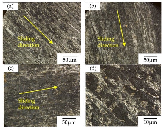
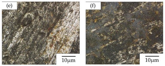
Figure 7.
Micro morphologies of worn surfaces of the pin at different loads (300 r/min, loam, moisture 0): (a,d) load of 2 N; (b,e) load of 5 N; (c,f) load of 8 N.
Figure 8 shows the micro morphologies of worn surfaces of the pin at different speeds. The experiment was performed under a soil type of loam, moisture of 0 and a normal load of 5 N. It can be clearly seen from the Figure 8 that the wear mechanism is dominated by abrasive wear and oxidation wear at the speed of 300 and 400 r/min (Figure 8a–e). Because there are many small hard sands in the soil, abrasive wear is common in this wear test. When the rotational speed is 600 r/min, adhesive wear occurred on the pin surface (Figure 8c,f). As the speed increases, the contact frequency between the worn surface of the pin and the worn surface of the disc is increasing. Therefore, the average temperature and the flash temperature of the wear surface between the pin and the disc also increases rapidly, which caused a small material on the surface of the disk to be transferred to the surface of the pin. Speed mainly affects the pin and disc wear test by increasing the temperature of the contact surface and the frequency of contact between the pin and the disc. Therefore, rotational speed has little effect on wear loss compared with the effect of load on wear loss (shown in Figure 5a). The influence of speed on the friction coefficient is very small, so the friction coefficient of three speeds is not very different (shown in Figure 5b).
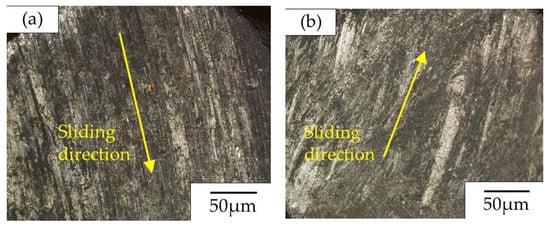
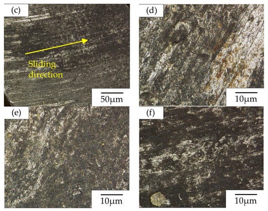
Figure 8.
Micro morphologies of worn surfaces of the pin at different speeds (5 N, loam, moisture 0): (a,d) speed of 300 r/min; (b,e) speed of 400 r/min; (c,f) speed of 600 r/min.
In order to simulate the actual working environment of peanut spring-finger as far as possible, this experiment set different soils and different humidities as environmental variables. Figure 9 shows the micro morphologies of worn surfaces of the pin at different soils. The experiment was performed under a rotating speed of 300 r/min, moisture of 10% and a normal load of 5 N. Figure 9 shows that the wear mechanism is dominated by abrasive wear. Because soil contains many organic matters, the influence of soil on wear test is relatively complicated compared with conventional wear test. It can be seen that the surface of the pin is relatively smooth, and there is no obvious deep scratched gully and less oxidation wear (Figure 9a–d). The sand content of clay and loam is less than that of sandy soil, so the wear loss in clay and loam is much less than that in sandy soil (Figure 6a). When the test conditions were clay and loam, the surface of the pin did not show adhesive wear and a large amount of oxidation wear, which indicated that the temperature of the worn surface was not particularly high. The wear loss in sand soil is very large, causing serious damage to the wear surface and increasing the temperature of the wear surface. However, it did not reach the temperature required for adhesive wear. It can be seen from the Figure 9c,f that the surface of the pin is relatively bright and there are many yellow spots on the surface, which is an obvious trace of mild oxidation wear.
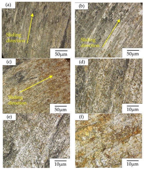
Figure 9.
Micro morphologies of worn surfaces of the pin at different soils (5 N, moisture 10%, 450 r/min): (a,d) soil of clay; (b,e) soil of loam; (c,f) soil of sandy.
Figure 10 shows the micro morphologies of the worn surfaces of the pin at different moistures. The experiment was performed under a sliding distance of 3000 m, a rotating speed of 300 r/min, a soil type of loam and normal load of 5 N. Figure 10a shows that the surface of the pin is marked by oxidation wear, abrasive wear and adhesive wear. In addition to the common abrasive wear, oxidative wear and adhesive wear, Figure 10d shows red-brown rust and light-yellow material on the surface of the pin. Some of the substances in the soil react with the pin at high temperatures, resulting in the formation of red-brown iron oxide locally. A yellow substance is formed by the embedding of soil to the wear surface during the transfer of materials at high temperatures. When the soil moisture is 10%, the presence of moisture in the soil reduces the average temperature of the worn surface and the wear mechanism is dominated by abrasive wear (shown in Figure 10b,e). When the soil moisture is increased to 20%, there is more water in the soil. Some substances in the soil dissolved in water and acted as a lubricant in the wear test, thus making the friction coefficient relatively small (Figure 6b). Some substance in the water solution reacted with the pin surface, which caused corrosion wear, making the surface of the pin darker (shown in Figure 10c,f). The hardness of dry soil is relatively high. During the wear test, the soil between the pin and the disc made the contact surface fluctuate and the flash temperature is relatively high. On the contrary, the contact surface is relatively stable when tested in wet soil. Therefore, the surface damage of the pin is serious when the soil moisture is 0, but the wear loss is much less than the soil moisture at 10% and 20% (Figure 6a).
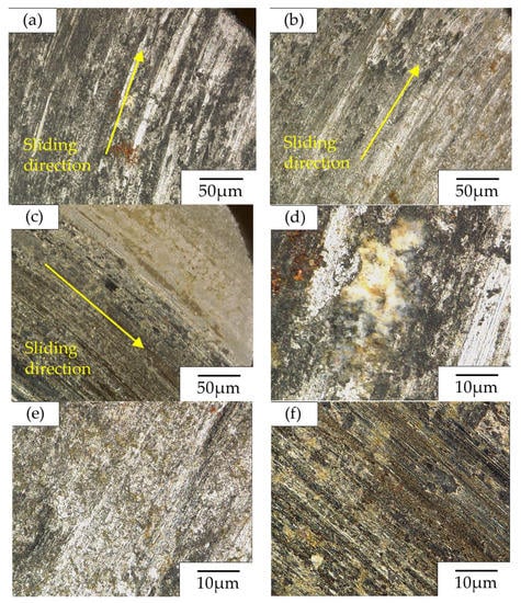
Figure 10.
Micro morphologies of worn surfaces of the pin at different moistures (5 N, loam, 450 r/min): (a,d) moisture of 0%; (b,e) moisture of 10%; (c,f) moisture of 20%.
4. Conclusions
According to the actual working environment of the peanut spring-finger, four variable parameters were set up: load, speed, soil moisture and soil type. The experimental results are as follows:
There are many small hard sands in the soil, so abrasive wear was common in this wear test. The adhesive wear occurs on the pin surface when the load is 8 N. The test results show that the wear loss increases with the increased load and the friction coefficient decreases with the increased load.
Speed mainly affected the pin and disc wear test by increasing the temperature of the contact surface and the frequency of the contact between the pin and the disc. Under the same experimental conditions, the larger the sliding speed was, the less the wear loss was. The influence of speed on friction coefficient is very small.
The wear loss of the pin is different under different soil conditions. The average wear loss in sandy soil is much greater than that in loam and clay. The reason for this result is that the sandy soil contains a large amount of sand particles, which caused the severe abrasive wear. Water in wet soil acted as a lubricant in the experiment, so the friction coefficient decreases with the increase in soil moisture. Wet soil makes the wear mechanism more complicated, so the wear loss in wet soil is much larger than that in dry soil.
Through the research in this paper, it is known that the wear loss of a peanut spring-finger is different under different conditions. The friction and wear characteristics of spring-finger materials (65Mn steel) are studied in this paper, which can provide a reference for the designers of peanut harvesters and improve the working life of peanut harvesters.
Author Contributions
Conceptualization, Z.L., C.D., Q.C., T.N., N.W. and W.S.; methodology, Z.L., C.D., Q.C., T.N., N.W. and W.S.; software, T.N., and C.D.; validation, Z.L., Q.C., and T.N.; formal analysis, C.D., T.N. and N.W.; investigation, Z.L. and N.W.; resources, N.W. and W.S.; data curation, Q.C.; writing—original draft preparation, Z.L., C.D. and Q.C.; writing—review and editing, Z.L., C.D., Q.C. and N.W.; visualization, T.N.; supervision, W.S.; project administration, Z.L.; funding acquisition, W.S. All authors have read and agreed to the published version of the manuscript.
Funding
This research was funded by National Key R&D Program of China (2018YFB1304504), the National Natural Science Foundation of China (Grant No. 52005085), Fundamental Research Funds for the Central Universities (Grant No. 2003017) and the general support project of China Postdoctoral Science Foundation (Grant No. 2018M631800).
Conflicts of Interest
The authors declare no conflict of interest.
References
- Noorhosseini, S.A.; Damalas, C.A. Environmental Impact of Peanut Production under Different Levels of Nitrogen Fertilization. Agriculture 2018, 8, 104. [Google Scholar] [CrossRef]
- Carneiro, A.P.; Rodríguez, O.; Macedo, E.A. Dissolution and fractionation of nut shells in ionic liquids. Bioresour. Technol. 2017, 227, 188–196. [Google Scholar] [CrossRef]
- Nascimento, M.S.; Carminati, J.A.; Silva, I.C.R.N.; Silva, D.L.; Bernardi, A.O.; Copetti, M.V. Salmonella, Escherichia coli and Enterobacteriaceae in the peanut supply chain: From farm to table. Food Res. Int. 2018, 105, 930–935. [Google Scholar] [CrossRef] [PubMed]
- Hu, Z.C. Study on Key Technologies of Half-feed Peanut Combine Harvester. Ph.D. Thesis, Nanjing Agricultural University, Nanjing, China, 2011. [Google Scholar]
- Sun, Q.W.; Wang, Y.Y.; Xu, Z.R. Application Situation and Progress Analysis of Peanuts Piecewise Harvest Machine. Agric. Mech. Res. 2012, 34, 234–237. [Google Scholar]
- Guan, M.; Zhao, B.Q.; Gao, L.X. Categories and Characteristics of Peanut Harvesting Machinery. Agric. Sci. Technol. Equip. 2013, 10, 34–36. [Google Scholar]
- Chai, H.H.; Yang, R.B.; Shang, S.Q. Design of 4SHWZ- 1800 Self- propelled and Segmented Peanut Harvester. J. Agric. Mech. Res. 2014, 36, 76–80. [Google Scholar]
- Zhichao, H.; Baoliang, P.; Wenqing, Y.; Hai’ou, W.; Lijia, T.; Lianglong, H. Design of 4LH2 type half-feed and self-propelled peanut combine. Trans. Chin. Soc. Agric. Eng. 2008, 24, 148–153. [Google Scholar]
- Xu, T. Design and Experiment Study on the Spring-finger Type of Peanut Pickup Device. Ph.D. Thesis, Shenyang Agricultural University, Shenyang, China, 2016. [Google Scholar]
- Tseng, C.F.; Lin, W.S. The processing and fracture analysis on transmission shafts of a peanut harvester. J. Mater. Process. Technol. 2008, 201, 374–379. [Google Scholar] [CrossRef]
- Del Río López, B.; García Diez, A.; Mier Buenhombre, J.L.; Camba Fabal, C.; Filgueira Vizoso, A. Microstructural Analysis and Tribology Behavior of a Medium-Mn Steel with Mo. Metals 2018, 8, 745. [Google Scholar] [CrossRef]
- Chen, S.L.; Cao, Z.X.; Wang, C.; Huang, C.X. Effect of volume fraction and mechanical stability of austenite on ductility of medium Mn steel. J. Iron Steel Res. Int. 2019, 11, 1209–1218. [Google Scholar] [CrossRef]
- Li, J.H.; Wang, H.H.; Luo, Q.; Li, L.; Sun, C.; Misra, R.D.K. Correlation between microstructure and impact toughness of weld heat-affected zone in 5 wt.% manganese steels. J. Iron Steel Res. Int. 2019, 26, 761–770. [Google Scholar] [CrossRef]
- Wang, H.; Zhao, Y.; Yuan, X. Effects of Boronizing Treatment on Corrosion Resistance of 65Mn Steel in two Acid Mediums. Phys. Procedia 2013, 50, 124–130. [Google Scholar] [CrossRef]
- Dong, C.J.; Zhang, J.H.; Xu, J.Y.; Song, X.C.; Zhao, Y.F. Microstructures and properties of electrical discharge strengthened layers on 65Mn steel. Appl. Surf. Sci. 2011, 257, 2843–2849. [Google Scholar] [CrossRef]
- Zhang, W.; Zhao, J.; Wang, G.; Qiao, Y.; Liang, X.; Sun, Y. Effects of Salt Bath Nitrocarburizing on Wear Resistance of 65Mn Spring Steel. Surf. Technol. 2017, 46, 127–132. [Google Scholar]
- Ucgul, M.; Fielke, J.M.; Saunders, C. Three-dimensional discrete element modelling (DEM) of tillage: Accounting for soil cohesion and adhesion. Biosyst. Eng. 2015, 129, 298–306. [Google Scholar] [CrossRef]
- Li, X.; Sosa, M.; Olofsson, U. A pin-on-disc study of the tribology characteristics of sintered versus standard steel gear materials. Wear 2015, 340–341, 31–40. [Google Scholar] [CrossRef]
- Godino, L.; Pombo, I.; Sanchez, J.A.; Izquierdo, B. An original tribometer to analyze the behavior of abrasive grains in the grinding process. Metals 2018, 8, 557. [Google Scholar] [CrossRef]
Publisher’s Note: MDPI stays neutral with regard to jurisdictional claims in published maps and institutional affiliations. |
© 2021 by the authors. Licensee MDPI, Basel, Switzerland. This article is an open access article distributed under the terms and conditions of the Creative Commons Attribution (CC BY) license (http://creativecommons.org/licenses/by/4.0/).