Article

Light Output, Thermal Properties, and Reliability of Using Glass Phosphors in WLED Packages

1
Department of Electrical Engineering, Institute of Microelectronics, National Cheng Kung University, Tainan 701, Taiwan
2
Green Energy Technology Research Center, Kun Shan University, Tainan 710, Taiwan
3
Department of Electrical Engineering, Kun Shan University, Tainan 710, Taiwan
*
Authors to whom correspondence should be addressed.
Coatings 2021, 11(2), 239; https://doi.org/10.3390/coatings11020239
Submission received: 29 December 2020 / Revised: 3 February 2021 / Accepted: 10 February 2021 / Published: 17 February 2021
(This article belongs to the Special Issue Advances in Thin Film Transistors: Properties and Applications)

Abstract

:
White-light-emitting diodes (WLED) based on yttrium aluminum garnet (YAG) phosphors sintered with glass (PiG) and with silicone (PiS) are compared in terms of their light properties, temperature properties and reliability.The complete YAG phosphor was doped with an encapsulant traditional WLED (PiS WLED), and the WLED was covered with PiG (PiG WLED). PiG was made by sintering glass powder and YAG phosphor at the ratio of 87:13 (%), and the correlated color temperature (CCT) was 5564 K. The CCT of the PiG WLED with the YAG doping concentration of 8.5 wt.% approximated 5649 K. The initial light output of the PiG WLED was 6.4% lower than that of the PiS WLED. Under 1008 h and 350 mA aging, PiG WLED and PiS WLED’ light output, CCT and color rendering index variation rates were all within 1%. In the saturated vapor-pressure test, no sample exhibited red ink infiltration, light nor peeling between the encapsulant and the lead-frame. Compared with that of the PiS WLED, the junction temperature of the PiG WLED reduced from 88.4 °C to 81.3 °C. Thermal resistance dropped from 37.4 °C/W to 35.6 °C/W. The PiG WLED presented a better CIE (Commission Internationale de l’Eclairage) 1931 chromaticity coordinate (x,y) concentration and thermal properties than the PiS WLED.

1. Introduction

The application of light-emitting diodes (LEDs) has become widespread, the amounts of light and power used have also increased, and the accompanying thermal problems have been relatively addressed and studied [1,2,3]. If the heat generated inside LEDs is not effectively dissipated to the external environment, the interface temperature will rise, brightness will decrease, the LED life-time will shorten, and the efficiency of phosphor excitation will drop. LEDs follow three heat dissipation mechanisms, namely heat conduction, heat convection, and heat radiation [4]. Most of the heat generated on the p-n side of the LED is transferred by the solid material under the chip, and then the heat is conducted out by the metal in the holder to the external heat sink fins or metal circuit substrate. Meanwhile, a small portion of the heat is transferred by heat convection and heat radiation through the packaging adhesive. This study investigated this part by using phosphor in glass (PiG) instead of phosphor in silicone (PiS). Conventional white LED (WLED) packaging is made by using yttrium aluminum garnet (YAG) phosphors mixed in an encapsulant with blue LED excitation. The higher the concentration of phosphor doping in the encapsulant, the easier it is for heat to accumulate inside the LED during operation. The lower the amount of phosphor doping concentration, the less heat accumulates inside the LED during operation, and the higher the efficiency of external heat transfer will be [5]. However, this problem cannot be solved by the adjustment of the phosphor concentration because phosphor concentration directly affects the CIE coordinates and correlated color temperature (CCT) of WLEDs. The precipitation problem of encapsulant mixed with phosphors [6,7] can be solved by sintering the phosphors in glass.
YAG phosphor in WLEDs exhibits problems associated with thermal quenching owing to the high operating current of LEDs [8,9,10,11,12]. With decreased LED efficiency as a function of higher operating current, the temperature of LEDs increases, and the LED efficiency is lost as heat. A glass-based carrier material has been proposed as a new solution for LED and laser-driven solid-state lightings [13,14,15,16] because PiG can withstand high temperatures. The traditional WLED packaging method involves using blue LED to excite YAG phosphor doped in the encapsulant. Previous researchers used chip-on-board packaging and gallium nitride (GaN) blue LED arrays to excite YAG PiGs and compare their light output and thermal properties with YAG PiS. The PiG WLED has high reliability and color uniformity. Through reliability tests, two different packaging structures, namely PiS and PiS, were compared, and the light output flux and thermal properties were discussed [17,18,19].

2. Materials and Methods

2.1. Materials

The lead-frame used in the experiment was a plastic-leaded chip carrier (PLCC, 5050, Chang Kai Tak Electronic Technology Co., Ltd., Dongguan, China) in surface-mount device (SMD) form with a size of 5050 (5.0 mm × 5.0 mm × 0.95 mm). The die-bonding silver paste used transparent silicone with a thermal conductivity of 0.2 W/(m·K). The horizontal structure of GaN blue wafer has a size of 45 mil × 45 mil, an optical power of 590 mW (at 350 mA operating current), and a dominant wavelength of 456 nm. The electrical connection between the LED chip and lead-frame was completed by gold wire bonding. The encapsulant used silicone with a refractive index of 1.54. The phosphor selected in this study was YAG phosphor with a peak emission-spectrum wavelength of 551 nm and a particle size of 13.5 μm.
Glass powder alkaline earth boro-aluminosilicate (Eagle 2000, Corning Incorporated, New York, NY, USA) was sintered together with phosphor. Alkaline earth boro-aluminosilicate has high light transmission and excellent thermal conductivity and thermostability. The refractive index, which affects the luminous efficiency, is about 1.5. The PiG was sintered with glass powder and YAG phosphor powder at the ratio of 87:13 (%); this phosphor was the same type as the YAG phosphor doped in silicone encapsulant. The PiG was produced by uniform mixing of phosphor and glass powders followed by extrusion molding with a machine before sending the glass to a high-temperature furnace for sintering. Afterwards, a massive phosphor ingot was obtained. After slicing to an appropriate thickness, the surface of the sliced phosphor was ground and polished. Finally, we used laser cutting to cut the phosphor into the required shape and thickness. The thickness of the PiG was 150 μm. With regard to the material properties, PiG has a higher glass transition temperature than PiS, and it is suitable for high-power lighting applications. Inorganic phosphors are produced using high-temperature and high-pressure processes, and they exhibit a low probability of cracking, increased mechanical strength of glass phosphors, and improved luminous efficiency. Compared with the PiS, the PiG is water absorbing and prone to oxidation of a silver-plated layer in a high-humidity environment, resulting in a significant change in the CCT of the WLED. At the same time, the PiG had high chemical stability, which reduced the oxidation problem of the silver-plating layer and improved the phosphor-aging problem to avoid the color shift of the lighting source and prolong the service life [20,21,22].

2.2. Experimental Procedure

Two structural samples were produced and compared in this study. Figure 1 shows the structure of the PiS WLED and the PiG WLED. We used PiG to cover the SMD and further studied its influence on light output, thermal properties, and reliability.
For chip bonding, the PLCC lead-frame was placed under the microscope, and the die-bonding silver paste was dotted onto the lead-frame center. The LED chip was placed on the silver paste to complete the bonding, and the LED with the chip was placed in an oven for curing. The curing parameter was to raise the temperature to 160 °C at room temperature, and the constant-temperature time was 120 min.
The phosphor ratio was adjusted. Under the operating current of 350 mA, the light properties of the integrating-sphere measurement system (ISP-500, Optimum Optoelectronics Co., Hsinchu County, Taiwan) were determined, and the ratio required for the experiment was adjusted based on the CCT of the measurement result. This study used a silicone encapsulant with a refractive index of 1.54. The silicone encapsulant has light-transmission properties. The ratio of the two-part silicone of AB was 1:2 by weight ratio. Part A is the main glue and Part B is the hardener. Vacuum and deaeration mixings were performed with a vacuum-deaeration mixer (KK-50S, KURABO, Osaka, Japan). A dispenser was used to pour the packaging gel into the holder bowl, and it was placed in the oven (RHD-452, CHEN CHENG INDUSTRIAL Co., Ltd, New Taipei City, Taiwan) for curing. The curing parameters were as follows: in the first stage, room temperature was raised to 60 °C, and it was kept constant for 30 min; the temperature was raised to 90 °C in the second stage, then kept constant for 1 min; it was raised to 120 °C in the third stage, and kept constant for 10 min; and it was raised to 150 °C in the fourth stage and kept constant for 120 min.
The CCT of the PiG WLED and the PiS WLED was controlled at 5649 ± 250 K to facilitate the measurement of optical and thermal properties and reliability analysis between the two types of WLEDs. The forward voltage method was used to measure the junction temperature (Tj) and convert the thermal resistance (Rth) [23,24]. The surface temperature (Ts) of the second layer of silicone encapsulant was measured with an infrared thermal imaging camera (TiR125, Fluke Co., Everett, Washington,, USA). We used a multi-channel temperature inspection recorder (GL-840M, GRAPHTEC Co., Yokohama, Japan) to record the LED case temperature (Tc) in real time. The light output of WLEDs was measured by an integrating sphere system (ISP-500, Optimum Optoelectronics Co., Hsinchu County, Taiwan).

3. Results and Discussion

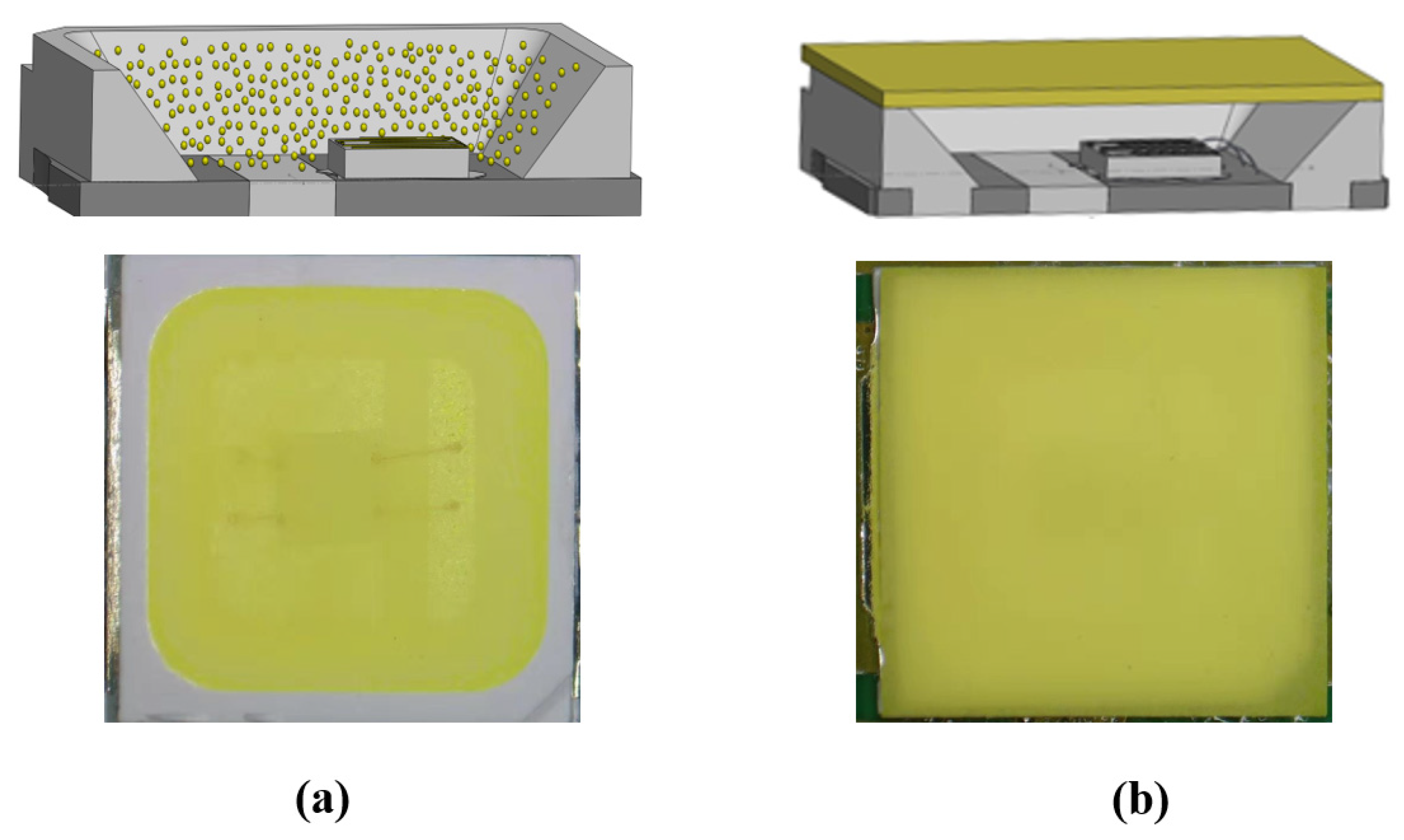
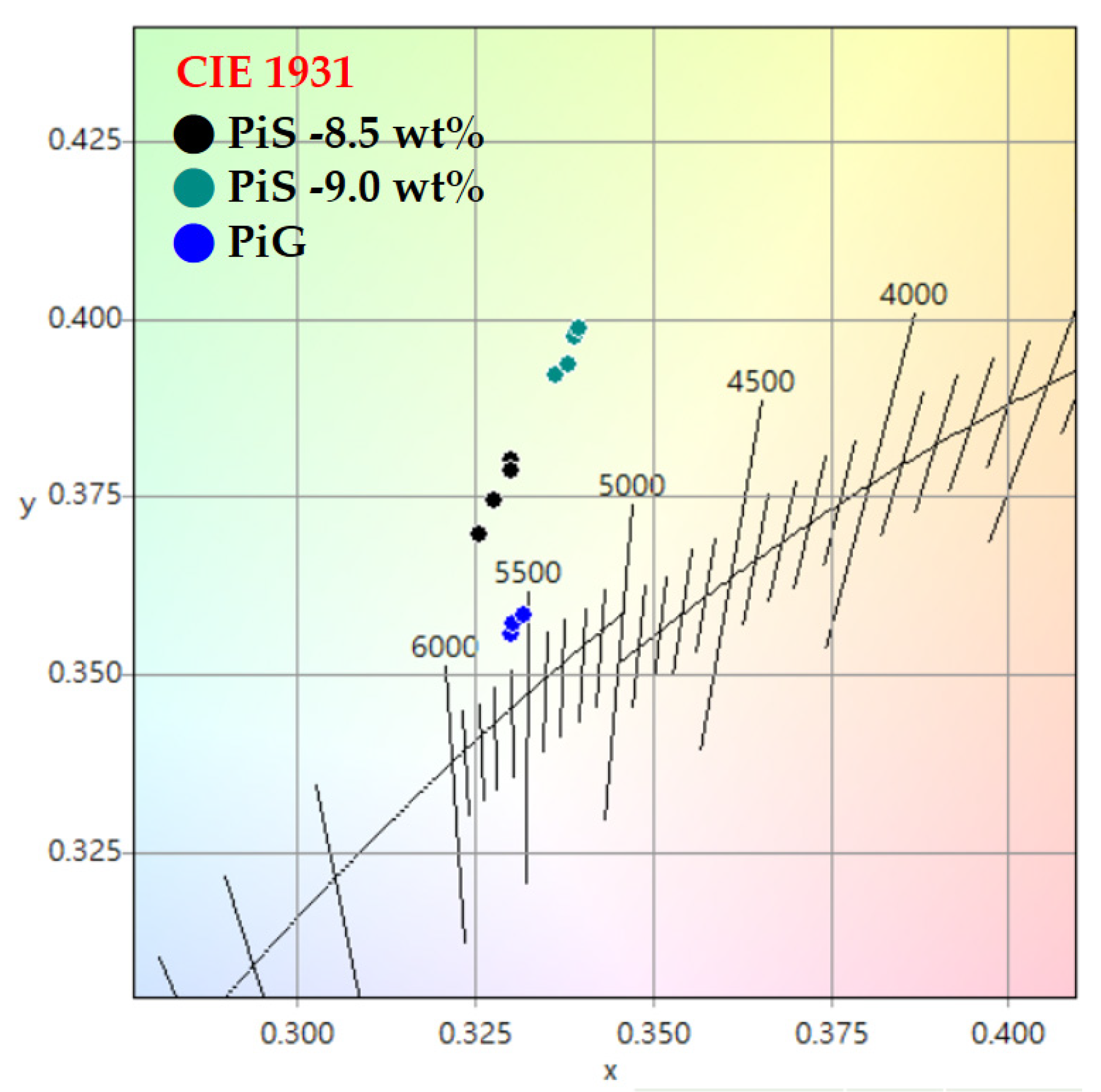
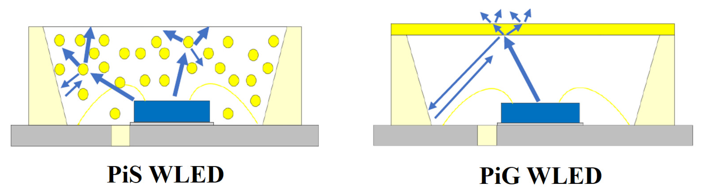
3.1. Light Properties

With the PiG WLED CCT of 5564 K as the standard, the PiS WLED was produced. As shown in Figure 2, the YAG phosphors were doped with the encapsulant at concentrations of 8.5 and 9 wt.%, and the CCTs were 5649 and 5311 K. The CCT of YAG phosphor doped at 8.5 wt.% concentration was close to that of the PiG WLED. Therefore, the YAG doping concentration ratio of 8.5 wt.% in the encapsulant was used for PiS WLEDs in this study.
Figure 2 shows the distribution of PiG WLED and PiS WLED samples in the CIE 1931 coordinate graph. PiG WLEDs had a lower CIE chromaticity coordinate shifting ratio and smaller CCT differences than the PiS WLEDs. Table 1 summarizes the deviations of CIE 1931 x and y coordinates and CCT for the PiS WLED (8.5 wt.%), the PiS WLED (9.0 wt.%), and PiG. The proportion of deviations of CIE1931 x and y coordinates on the same axis was discussed. The deviation values of CIE1931 x and y coordinates were 0.4% and 0.7% for the PiS WLED (8.5 wt.%), respectively, and the values were 1.4% (x) and 2.7% (y) for the PiG WLED. The light output flux of PiS WLEDs and PiG WLEDs were measured and compared by using an integrating sphere at an operating current of 350 mA. Table 2 shows the light output flux and light output flux efficiency of PiS WLEDs and PiG WLEDs. The light output flux of the PiS WLED and the PiG WLED was 142.4 and 133.2 lm, respectively. Meanwhile, the light output flux efficiencies were 118 (PiS WLED) and 110 (PiG WLED) lm/W.
Figure 3 shows the light-emitting path of the PiS WLED and the PiG WLED. We observed that in the yellow light emitted by the phosphor of the PiS WLED, blue light was emitted in all directions, and a small part of the light was refracted back to the interior and then reflected through the cavity of the lead-frame. The white light emitted by the PiG WLED blue excitation phosphor was also emitted in all directions. However, a part of the light was completely reflected or refracted back to the interior owing to the interface between the phosphor and the encapsulant, and it was reflected again through the light-receiving cavity of the lead-frame. Another part of the light was refracted back to the phosphor glass, and the light loss of repeated reflections resulted in the lower light output of the PiG WLED than that of the PiS WLED.

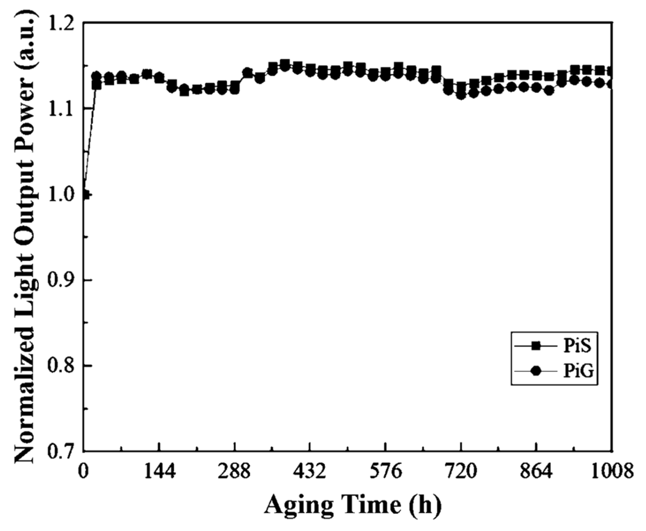
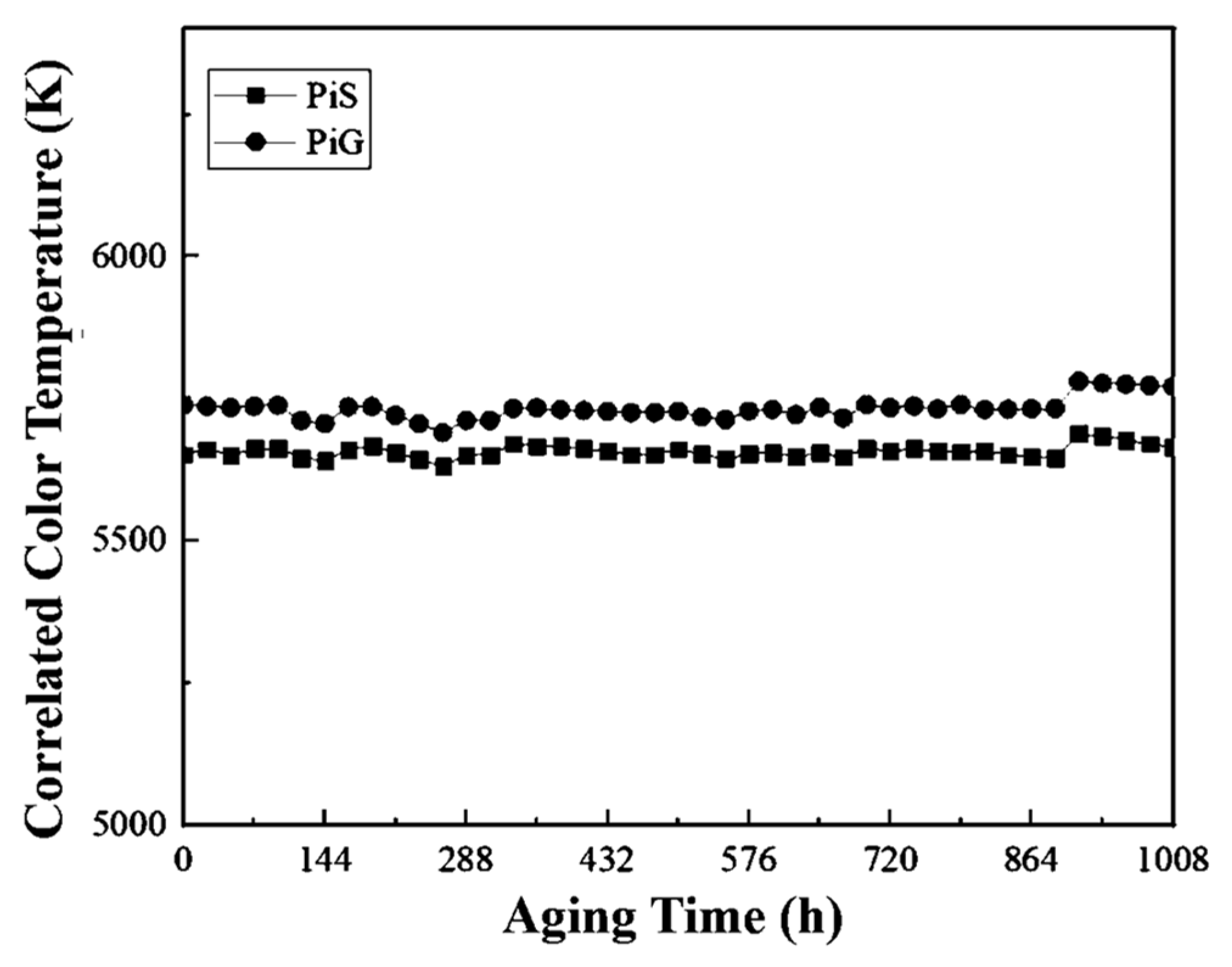
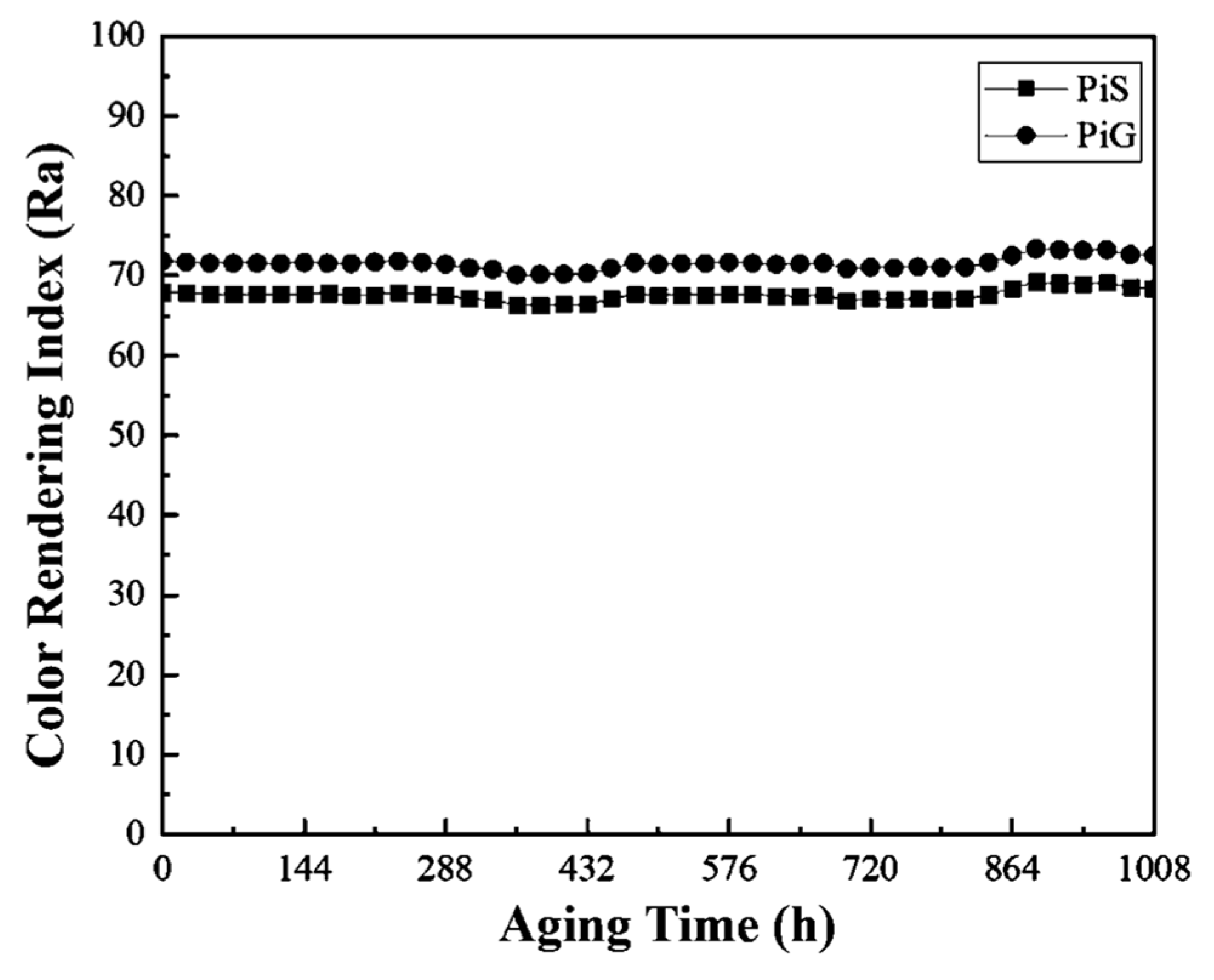
3.2. Dynamic Aging at Room Temperature

Dynamic aging was performed at room temperature at the operating current of 350 mA for 1008 h to the capture light output flux, CCT, and color rendering index (CRI). Figure 4 shows that the normalized light output flux drift of the PiG WLED and the PiS WLED for 1008 h reached 110% and 111% of the initial value, respectively. Figure 5 shows the CCT drifts of the PiG WLED (+0.5%) and the PiS WLED (+0.2%). Figure 6 shows the CRI drifts of the PiG WLED and the PiS WLED at 0.8% and 0.7%, respectively. Table 3 summarizes the above measurement results. The light output flux, CCT, and CRI of PiG WLEDs and PiS WLEDs were consistent and showed almost no variation before and after aging.

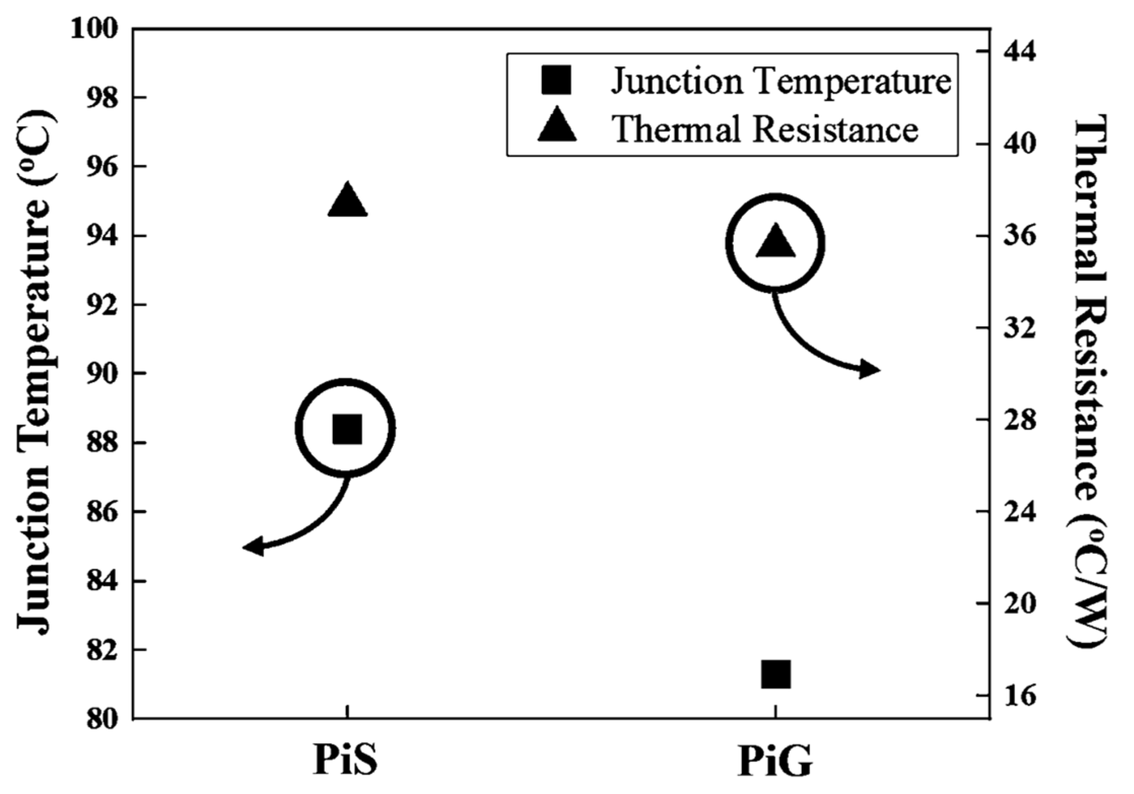
3.3. Thermal Properties

Figure 7 shows the Tj of the PiG WLED and the PiS WLED measured by the forward voltage method at a 350 mA operating current [24]. In accordance with JEDEC (Joint Electron Device Engineering Council) Standard No. 51-1, the Rth of a single semiconductor device was converted [24,25]. The y-axis on the left of Figure 7 is the Tj of the PiS WLED and the PiG WLED, and the y-axis on the right is the Rth of the PiS WLED and the PiG WLED obtained using the Rth formula. The Rth of a single semiconductor device is defined in Equation (1):
Rth = (TjTx)/P
where Rth is the thermal resistance between the device junction and a specific environment, Tj is the junction temperature of the device in a steady state condition, Tx is the reference temperature for the specific environment, and P is power dissipation in the device. In this study, the reference temperature was the Tc. A multi-channel temperature inspection recorder was used to record the LED Tc instantaneously.
The Tj of the PiG WLED and the PiS WLED was 81.3 °C and 88.4 °C, respectively, and the Rth was 35.6 °C/W (PiG WLED) and 37.4 °C/W (PiS WLED). Table 4 summarizes the measurement results of the thermal properties of the PiG WLED and the PiS WLED.

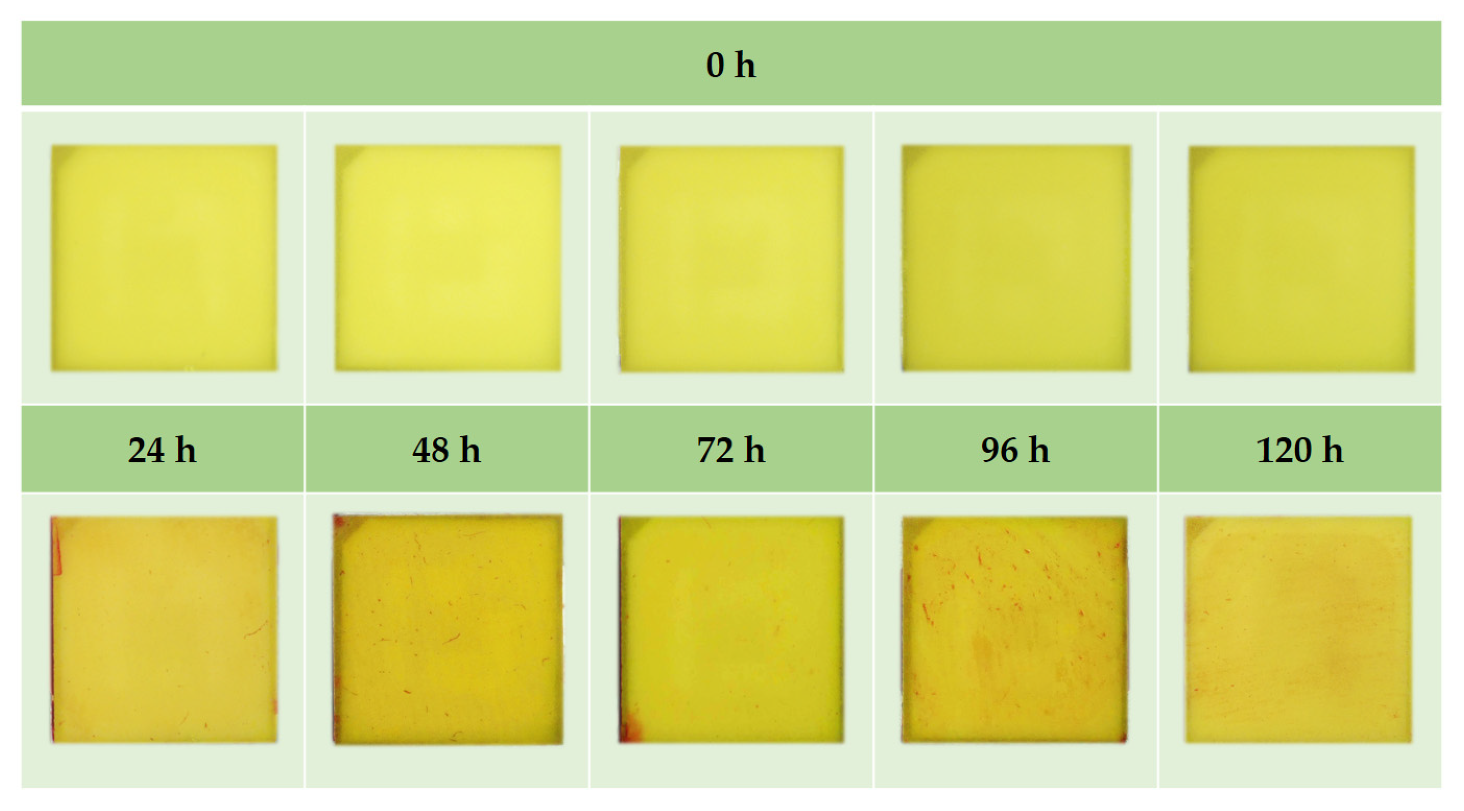
3.4. Saturated Vapor-Pressure Test

Samples were heated at 121 °C, with the cavity pressure greater than 1 atmosphere and the impact duration lasting for 120 h. During the test, two samples were retrieved every 24 h to light up and were soaked in red ink, and the absence of brightening or peeling of the glue from the lead-frame was observed. Two samples of 25 pieces each did not show the phenomenon of non-brightness, and no infiltration of red ink was recorded after dipping. Figure 8 shows the external photo of the PiG WLED after the impact duration of saturated vapor-pressure test and the completion of red ink immersion.

4. Conclusions

The CIE 1931 (x,y) distribution of PiG WLEDs was more concentrated than that of PiS WLEDs. The CIE 1931 x and y coordinate deviations for the PiG WLED were 0.4% and 0.7%, respectively. Meanwhile, the values for the PiS WLED reached 1.4% (x) and 2.7% (y). The PiG WLED exhibited a more concentrated distribution of CIE 1931 (x,y) and CCT. The drift range of the PiG WLED CCT was from −44 to +21 K, which indicates a better concentration compared with that of the PiS WLED CCT at −69 to +113 K. No significant difference was observed in the light output, CCT, and CRI drift between the PiG WLED and the PiS WLED at an operating current of 350 mA during 1008 h of aging at room temperature. As for the thermal properties, the PiG WLED Tj decreased from 88.4 to 81.3 °C, and the Rth decreased from 37.4 to 35.6 °C/W compared with those of the PiS WLED. In the saturated vapor pressure test, the PiG WLED showed the same excellent material bonding strength as the PiS WLED, and no unlit or red ink infiltration samples were found.
Therefore, PiG WLEDs had better color temperature and concentration of color coordinates, but a slightly lower light output flux than PiS WLEDs. Compared with PiS WLEDs, the PiG WLEDs showed a better performance in terms of the thermal properties (Tj and Rth). PiG WLEDs can also attain similar results to PiS WLEDs under normal-temperature aging and saturated vapor-pressure test conditions.

Author Contributions

Conceptualization, C.-C.H. and T.-H.W.; Methodology, C.-C.H. and T.-H.W.; Validation, C.-C.H., T.-H.W., C.-L.L., and Y.-K.S.; Formal Analysis, C.-C.H. and T.-H.W.; Resources, C.-C.H., C.-L.L., and Y.-K.S.; Data Curation, C.-C.H., C.-L.L., and Y.-K.S.; Writing—Original Draft Preparation, C.-C.H. and T.-H.W.; Writing—Review and Editing, C.-C.H., T.-H.W., C.-L.L., and Y.-K.S. All authors have read and agreed to the published version of the manuscript.

Funding

This work was supported in part by the Ministry of Science and Technology of Taiwan, ROC, under Grant MOST 107-2221-E006-185-MY3 and Grant 108-2221-E-006-201-MY3, and in part by the Green Energy Technology Research Center, Department of Electrical Engineering, Kun Shan University, Tainan, Taiwan through The Featured Areas Research Center Program within the framework of the Higher Education Sprout Project by the Ministry of Education in Taiwan.

Data Availability Statement

Not applicable.

Conflicts of Interest

The authors declare no conflict of interest.

References

  1. Narendran, N.; Gu, Y.; Freyssinier-Nova, J.P.; Zhu, Y. Extracting phosphor-scattered photons to improve white LED efficiency. Phys. Status Solidi 2005, 202, R60–R62. [Google Scholar] [CrossRef]
  2. Chung, T.Y.; Chiou, S.C.; Chang, Y.Y.; Sun, C.C.; Yang, T.H.; Chen, S.Y. Study of temperature distribution within pc-WLEDs using the remote-dome phosphor package. IEEE Photonics J. 2015, 7, 1–11. [Google Scholar] [CrossRef]
  3. Shih, B.-J.; Chiou, S.-C.; Hsieh, Y.-H.; Sun, C.-C.; Yang, T.-H.; Chen, S.-Y.; Chung, T.-Y. Study of temperature distributions in pc-WLEDs with different phosphor packages. Opt. Express 2015, 23, 33861–33869. [Google Scholar] [CrossRef]
  4. Lai, W.; Liu, X.; Chen, W.; Lei, X.; Cao, X. Thermal properties analysis of die attach layer based on time-constant spectrum for high-power LED. IEEE Trans. Electron Devices 2015, 62, 3715–3721. [Google Scholar] [CrossRef]
  5. Ma, Y.; Hu, R.; Yu, X.; Shu, W.; Luo, X. A modified bidirectional thermal resistance model for junction and phosphor temperature estimation in phosphor-converted light-emitting diodes. Int. J. Heat Mass Transf. 2017, 106, 1–6. [Google Scholar] [CrossRef]
  6. Chen, D.; Xiang, W.; Liang, X.; Zhong, J.; Yu, H.; Ding, M.; Lu, H.; Ji, Z. Advances in transparent glass–ceramic phosphors for white light-emitting diodes—A review. J. Eur. Ceram. Soc. 2015, 35, 859–869. [Google Scholar] [CrossRef]
  7. Deng, Y.; Lu, Q.; Yao, K.; Zhou, N. Study on phosphor powder precipitation model in flexible material manufacturing process based on neuro-fuzzy network. Optik 2018, 168, 563–576. [Google Scholar] [CrossRef]
  8. Lakshmanan, A.; Kumar, R.S.; Sivakumar, V.; Thomas, P.C.; Jose, M.T. Synthesis, photoluminescence and thermal quenching of YAG:Ce phosphor for white light emitting diodes. Indian J. Pure Appl. Phys. 2011, 49, 303–307. [Google Scholar]
  9. Lin, Y.C.; Bettinelli, M.; Sharma, S.K.; Redlich, B.; Speghini, A.; Karlsson, M. Unraveling the impact of different thermal quenching routes on the luminescence efficiency of the Y3Al5O12:Ce3+ phosphor for white light emitting diodes. J. Mater. Chem. C. 2020, 8, 14015–14027. [Google Scholar] [CrossRef]
  10. Kim, Y.H.; Arunkumar, P.; Kim, B.Y.; Unithrattil, S.; Kim, E.; Moon, S.H.; Hyun, J.Y.; Kim, K.H.; Lee, D.H.; Lee, J.S.; et al. A zero-thermal-quenching phosphor. Nat. Mater. 2017, 16, 543–550. [Google Scholar] [CrossRef] [PubMed]
  11. Lin, C.C.; Liu, R.S. Advances in phosphors for light-emitting diodes. J. Phys. Chem. Lett. 2011, 2, 1268–1277. [Google Scholar] [CrossRef] [PubMed]
  12. Tucureanu, V.S.; Alina, M.; Avram, A.M. Synthesis and characterization of YAG:Ce phosphors for white LEDs. Optic−Electron. Rev. 2015, 23, 239–251. [Google Scholar] [CrossRef] [Green Version]
  13. Wieg, A.T.; Penilla, E.H.; Hardin, C.L.; Kodera, Y.; Garay, J.E. Broadband white light emission from Ce:AlN ceramics: High thermal conductivity down-converters for LED and laser-driven solid state lighting. APL Mater. 2016, 4, 126105. [Google Scholar] [CrossRef]
  14. Song, Y.H.; Ji, E.K.; Jeong, B.W.; Jung, M.K.; Kim, E.Y.; Yoon, D.H. High power laser-driven ceramic phosphor plate for out-standing efficient white light conversion in application of automotive lighting. Sci. Rep. 2016, 6, 31206. [Google Scholar] [CrossRef] [PubMed]
  15. Raukas, M.; Kelso, J.; Zheng, Y.; Bergenek, K.; Eisert, D.; Linkov, A.; Jermann, F. Ceramic phosphors for light conversion in LEDs. ECS J. Solid State Sci. Technol. 2012, 2, R3168–R3176. [Google Scholar] [CrossRef]
  16. Wierer Jr, J.J.; Tsao, J.Y. Advantages of III-nitride laser diodes in solid-state lighting. Phys. Status Solidi 2014, 22, 1–6. [Google Scholar] [CrossRef]
  17. Zhang, X.; Yu, J.; Wang, J.; Zhu, C.B.; Zhang, J.H.; Zou, R.; Lei, B.F.; Liu, Y.L.; Wu, M.M. Facile preparation and ultrastable performance of single-device white-light-emitting phosphor-in-glass used for high-power warm white LEDs. ACS Appl. Mater. Interfaces 2015, 7, 28122–28127. [Google Scholar] [CrossRef]
  18. Zhang, R.; Lin, H.; Yu, Y.; Chen, D.; Xu, J.; Wang, Y. A new-generation color converter for high-power white LED: Transparent Ce3+:YAG phosphor-in-glass. Laser Photon- Rev. 2014, 8, 158–164. [Google Scholar] [CrossRef]
  19. Yoon, H.C.; Yoshihiro, K.; Yoo, H.; Lee, S.W.; Oh, J.H.; Do, Y.R. Low-Yellowing phosphor-in-glass for high-power chip-on-board white LEDs by optimizing a low-melting Sn-P-F-O glass matrix. Sci. Rep. 2018, 8, 1–11. [Google Scholar] [CrossRef] [Green Version]
  20. Chang, Y.-P.; Chang, J.-K.; Cheng, W.-C.; Kuo, Y.-Y.; Liu, C.-N.; Chen, L.-Y.; Cheng, W.-H. New scheme of a highly-reliable glass-based color wheel for next-generation laser light engine. Opt. Mater. Express 2017, 7, 1029–1034. [Google Scholar] [CrossRef]
  21. Kim, S.; Kim, B.; Kim, H. Optical properties of densified phosphor-in-glass LED encapsulants by spark plasma sintering. Opt. Mater. Express 2017, 7, 4304–4315. [Google Scholar] [CrossRef]
  22. Xu, X.; Li, H.; Zhuo, Y.; Xiong, D.; Chen, M.X. Gradient refractive index structure of phosphor-in-glass coating for packaging of white LEDs. J. Am. Ceram. Soc. 2019, 102, 1677–1685. [Google Scholar] [CrossRef]
  23. Xi, Y.; Schubert, E.F. Junction–temperature measurement in GaN ultraviolet light-emitting diodes using diode forward voltage method. Appl. Phys. Lett. 2004, 85, 2163–2165. [Google Scholar] [CrossRef] [Green Version]
  24. Kim, L.; Choi, J.H.; Jang, S.H.; Shin, M.W. Thermal analysis of LED array system with heat pipe. Thermochim. Acta 2007, 455, 21–25. [Google Scholar] [CrossRef]
  25. Standard No. 51-1 Integrated Circuits Thermal Measurement Method—Electrical Test Method (Single Semiconductor Device); JEDEC: Arlington, VA, USA, 1995.
Figure 1. Schematic and top view of (a) phosphor in silicone white-light-emitting diode (PiS WLED) and (b) phosphor in glass (PiG) WLED.
Coatings 11 00239 g001
Figure 2. PiS WLED doped with 8.5 and 9 wt.% yttrium aluminum garnet (YAG) phosphors and the PiG WLED CIE coordinate distribution of the covered PiG.
Coatings 11 00239 g002
Figure 3. Schematic of PiS WLED and PiG WLED light path.
Coatings 11 00239 g003
Figure 4. Normalized light output flux drift of PiS WLED and PiG WLED at 350 mA for 1008 h.
Coatings 11 00239 g004
Figure 5. CCT drift of PiS WLED and PiG WLED at 350 mA for 1008 h.
Coatings 11 00239 g005
Figure 6. Color rendering index (CRI) drift of PiS WLED and PiG WLED at 350 mA for 1008 h.
Coatings 11 00239 g006
Figure 7. Tj and Rth of PiS WLED and PiG WLED.
Coatings 11 00239 g007
Figure 8. Saturated vapor-pressure test of PiG: appearance of red ink in samples soaked every 24 h.
Coatings 11 00239 g008
Table 1. Light properties of PiS WLED doped with 8.5 and 9 wt.% YAG phosphors and PiG WLED covered with phosphor glass.
SampleCCT (K)CCT Difference Range (K)CIE 1931 x,y
PiG5564−44–+21(0.3306, 0.3750)
PiS 8.5 wt.% 5469−69–+113(0.3278, 0.3746)
PiS 9.0 wt.% 5311−39–+61(0.3382, 0.3937)
Table 2. Light output flux of PiS WLED and PiG WLED.
SampleLight Output Flux (lm) Light Output Flux Efficiency (lm/W)
PiS142.4 lm118 lm/W
PiG133.2 lm110 lm/W
Table 3. Normalized light output flux, CCT, and CRI of PiS WLED and PiG WLED, and measured data before and after 350 mA lighting for 1008 h.
SampleNormalized
Light Output Flux (%)
CCT (K)CRI (Ra)
0 h1008 hΔAverage (%)0 h1008 hΔAverage (%)
PiS111%56525664+0.267.968.4+0.7
PiG110%57385771+0.571.872.4+0.8
Table 4. Thermal properties of PiS WLED and PiG WLED.
SampleTj (°C)Tc (°C)TjTc (°C)Rth (°C/W) ΔRth (%)
PiS88.456.831.637.4NA
PiG81.351.030.335.6−4.0
Publisher’s Note: MDPI stays neutral with regard to jurisdictional claims in published maps and institutional affiliations.

