Article

Long-Term Atmospheric Aging and Corrosion of Epoxy Primer-Coated Aluminum Alloy in Coastal Environments

Aeronautics Engineering College, Air Force Engineering University, Xi’an 710051, China
*
Author to whom correspondence should be addressed.
Coatings 2021, 11(2), 237; https://doi.org/10.3390/coatings11020237
Submission received: 18 January 2021 / Revised: 3 February 2021 / Accepted: 11 February 2021 / Published: 17 February 2021

Abstract

:
Aircraft are subjected to extreme weather conditions in coastal areas. This study reports long-term atmospheric exposure tests carried out on an epoxy primer-coated aluminum alloy in a coastal environment for 7, 12, and 20 years. The micromorphology and characteristics of the section and surface, the products of corrosion, electrochemical impedance, and molecular structure of the coated specimens were examined through a spectrophotometer, scanning electron microscopy (SEM), atomic force microscopy (AFM), X-ray diffraction (XRD), electrochemical impedance spectroscopy (EIS), and X-ray photoelectron spectrometer (XPS). The results showed that the angles of contact of the specimens with different numbers of years of atmospheric exposure satisfied the normal distribution. Their fractal dimensions increased with an increase in the duration of exposure. Intergranular corrosion and exfoliation corrosion appeared in the specimens after 20 years, where the product of corrosion was Al(OH)3. The impedances and thermal properties of the epoxy coatings were influenced by the synergistic effects of aging and post-curing. The impedances of the coatings decreased greatly after long-term atmospheric exposure. After 20 years of corrosion, the specimen showed the characteristics of the substrate being corroded. The mechanism of corrosion and the electrochemical equivalent circuit were also analyzed.

1. Introduction

To prevent damage to the aluminum alloys used in aircraft structures due to corrosion, a double-layer protection system consisting of epoxy primers along with an anodized film of sulfuric acid has been used as a protection measure [1,2]. Because aircraft are on the ground for most of the time, the main corrosive environment for them is the ground atmosphere, where the coastal atmosphere has the most significant impact on the safety of the structure of aircraft [3,4,5,6]. Qiao et al. [7] investigated the corrosion kinetics and patina (corrosion products) layer evolution of galvanized steel submitted to wet/dry cyclic corrosion tests in a simulated coastal–industrial atmosphere. Sun et al. [8,9] carried out outdoor atmospheric exposure tests on the aluminum alloys 2024 and 7075 with and without aluminum coating in Beijing, Wanning, and Jiangjin, in China, to represent urban, coastal, and industrial atmospheric environments, respectively. After a 20-year exposure test, they found that the products of corrosion were γ-Al(OH)3 and α-Al2O3·3H2O. The pitting corrosion on the surface of the two aluminum alloys with aluminum coatings did not penetrate their surfaces, and both maintained good static performance.
The aging of epoxy coatings and the corrosion of coated aluminum alloys are the two most important factors influencing the failure of coatings [10]. The aging of the coating is usually characterized by a loss of gloss, discoloration, pulverization, embrittlement, and cracking [11,12,13]. Three important material-related factors that determine the failure of the coating are water, oxygen, and corrosive ions [14,15,16]. From the point of view of the coating itself, it includes the corrosion resistance of the substrate in the coating, the extent of the pigment corrosion resistance, coating defects and other factors [17,18,19]. Ramezanzadeh investigated the hydrolytic aging process of epoxy coatings and proposed a mechanism to explain this. Research has also suggested that the –C–O–C– chain in the epoxy coatings has a low degree of cross-linking, which is prone to hydrolytic fractures and results in the formation of pores and microscopic defects on the surface. This degrades their protection-related performance [20]. Liu et al. [21] investigated the evolution of the chemical functional groups, microstructure, and properties of the water barrier of a polyamide-cured epoxy (diglyceryl ether of bisphenol-A epoxy resin, DGEBA) coating exposed to ultraviolet A (UV-A) photo-oxidative aging.
This study examines the processes of corrosion and degradation of epoxy primer-coated 7075-T6 aluminum alloys in the atmosphere over the long term. Changes in the rate of gloss loss, the off-color rate, and contact angle with the duration of corrosion were compared in the long-term in an atmospheric environment. Furthermore, electrochemical impedance spectroscopy (EIS) was used to explore the changes in the corrosion resistance of the specimens as a function of the duration of corrosion. In addition, the surface and cross-sectional morphologies, as well as the products of corrosion of the epoxy primer-coated specimens, were analyzed using scanning electron microscopy (SEM), atomic force microscopy (AFM), electron probe microanalysis (EPMA), and energy dispersive spectroscopy (EDS). Finally, X-ray photoelectron spectrometer (XPS), thermo-gravimetric analyzer (TGA), and differential scanning calorimeter (DSC) were used to examine changes in the molecular structure and thermal properties of the epoxy coatings after exposure for different durations.
Research in this paper shows that the contact angles of the specimens with different atmospheric durations of exposure satisfied a normal distribution. The wettability of the surface of the epoxy coatings improved owing to hydrophilic groups produced by aging, and the contact angle decreased with the duration of exposure. The surface roughness increased gradually in the first 12 years, but decreased after 20 years of exposure. Significant intergranular corrosion and exfoliation corrosion occurred in the area where the coating had peeled, and the product of corrosion was Al(OH)3. The impedances and thermal properties of the epoxy coatings were influenced by the synergistic effects of aging and post-curing.

2. Experiment

2.1. Specimens

The substrates were composed of 7075-T6 aluminum alloy; their geometric shapes are shown in Figure 1. A double-layer protection system consisting of an “anodic oxidation film + epoxy primer” was used for the specimens [22]. The aluminum substrates were anodized with sulfuric acid and sealed with hot water. The thickness of the layer was about eight microns. The paint was atomized with compressed air, and all surfaces of the specimens were sprayed with epoxy primer within 24 hours. After having been dried, the average thickness of the epoxy primer was measured at about 50 microns. The chemical composition of the aluminum alloy substrates is shown in Table 1 [1].

2.2. Atmospheric Exposure Test

To simulate the structure of the interior aluminum alloy of a ground aircraft in coastal areas, especially the environment of the interior structure of the non-enclosed cabin, coastal atmospheric exposure tests were carried out for 7, 12, and 20 years in ventilated rooms of the Wanning Natural Environment Test Station (Wanning Station) in Hainan province, China. This was 350 m from the coastline, as shown in Figure 2. The Wanning Station is located at longitude 110° 30′ 31″ and latitude 18° 58′ 05″ north, as shown in Figure 2a. It has typical humid and hot oceanic atmospheric environment, characterized by a high concentration of chloride ions. Table 2 lists the annual average of atmospheric environmental data for the station in 1997. Data for different numbers of years are available on the website of the China Gateway to Corrosion and Protection [23]. All epoxy-coated specimens were placed horizontally on the test racks in the ventilation rooms according to ISO 8565:2011 [24]. After 7, 12, and 20 years of exposure, five epoxy-coated specimens were withdrawn and kept in a desiccator.

2.3. Micromorphological Characteristics of Surface and Cross-Section

2.3.1. Gloss, Chroma, and Contact Angle

The gloss and the chromatic values of each epoxy coating after different durations of exposure were measured by using the VS3200 non-contact spectrophotometer (X-rite, Grand Rapids, MI, USA) and iQC software (Basic), manufactured by X-rite (Grand Rapids, MI, USA). The measuring aperture was 12 mm. At least five locations were measured to obtain an average value. The loss of gloss of the epoxy-coated specimens was calculated as shown in Equation (1):
GL = (G0G)/G0 × 100
where GL is the loss of gloss, G0 is the gloss of the specimen without corrosion and aging, and G is the gloss of the specimen after several years of exposure.
The chromatic difference between each pair of exposed and unexposed specimens was measured by Equation (2):
E = L 2 + a 2 + b 2
where E is the chroma, L represents the shade of the color, a represents the red–green direction, and b represents the yellow–blue direction.
The contact angles of the exposed epoxy coatings were measured using a CA100C contact angle measuring instrument, manufactured by Innuo Precision Instruments Company (Shanghai, China). The contact angle formed by 6 μL drops of deionized water on the surface of each exposed specimen was calculated. The average value for 20 points on the surface of the coating of the same sample was taken as the contact angle of the sample.

2.3.2. Surface and Sectional Appearance

Microscopic morphology and elemental composition analysis were employed using SEM (VEGA II XMU, TESCAN, Shanghai, China) and EDS (OXFORD 7718, TESCAN, Shanghai, China). The area of the corrosion pits on the surface was analyzed by Image Pro Plus 6.0 software. The cross-sectional slices of each sample were ground with 1000-grit SiC paper, and the elemental distribution of the area of exfoliation corrosion of the specimen exposed for 20 years was obtained using EPMA (OXFORD 7718, TESCAN, Shanghai, China). The topography of the three kinds of specimens exposed for different durations were characterized by using an atomic force microscope (AFM, INNOVA, Veeco, NY, USA) with a transverse resolution of 0.2 nm (XY direction) and an XYZ standard scanner: 30 μm × 30 μm × 5 μm. In the phase mode, the probe type was NSC18/CR-Aubs (MikroMasch, Sofia, Bulgaria).

2.4. Electrochemical Measurement

A PARSTAT2273 electrochemical workstation (AMETEK, Princeton, NJ, USA) was used to measure electrochemical impedance. The measurement device was a three-electrode system. The auxiliary electrode was made of platinum, the reference electrode was a saturated calomel electrode (SCE), and the working electrode was an epoxy coating sample. Three locations were selected for each epoxy-coated specimen. The electrochemical measurements were taken once the samples had been immersed in 3.5 wt.% neutral sodium chloride solution for 20 min. When the open circuit potential (OCP) was stable, polarization curves of different samples were acquired at a scanning rate of 0.5 mV/s, and potential ranging from −0.25 VSCE to 0.25 VSCE with respect to the free corrosion potential (Ecorr). When measuring electrochemical impedance, the range of the frequency of measurement was 100 kHz–10 MHz, and the disturbance voltage applied was 25 mV. The fitting of the equivalent circuit was completed using ZSimpWin software (V3.61).

2.5. Characterization of Epoxy Coatings

The surface elemental composition and content of the coatings were measured using an ESCALAB Xi+ Type X-ray photoelectron spectrometer (XPS) from ThermoFisher Scientific, Waltham, Massachusetts, USA. Peak fitting was performed using Thermo Avantage software (V5.967). The source of excitation was a double-positive Al/Mg target, and the bond energy was adjusted by the main peak C1s at 284.6 eV.
A diamond DSC differential scanning calorimeter (PESTA8000), manufactured by Perkin Elmer Instruments Co., Ltd. (Waltham, MA, USA), was used to measure the influence of the duration of exposure on the glass transition temperature of the epoxy coatings. The weight of the tested samples was 20 mg, the temperature ranged from −30 °C to 150 °C, the rate of heating was 10 °C/min, and nitrogen was used as the atmosphere. A Pyris1 thermo-gravimetric analyzer (Q50, TA, New Castle, DE, USA) was used to measure the relationship between the mass and temperature of the substance. This was performed to measure the change in weight and rate of change of the substance with temperature and time.

3. Results and Discussion

3.1. Surface Characterization

3.1.1. Analysis of Gloss, Chroma, and Contact Angle

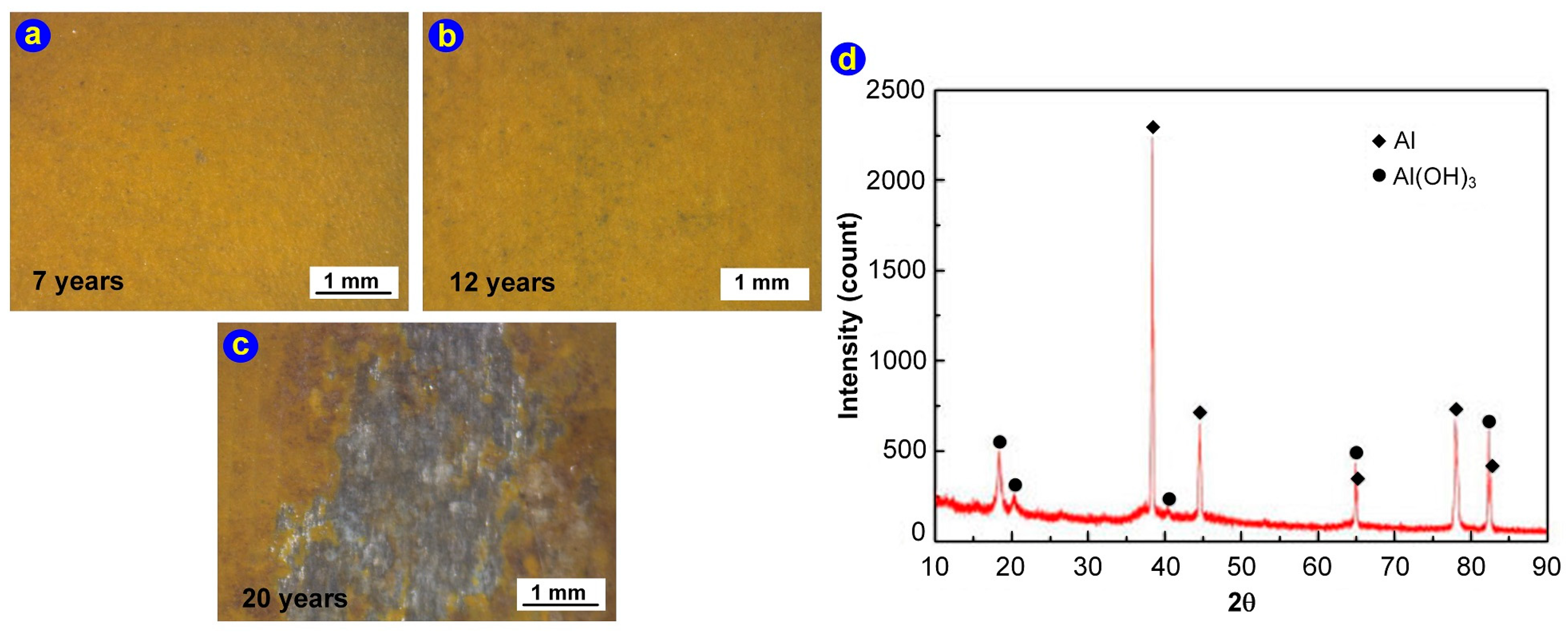
Figure 3a shows the surface morphology of the epoxy primer-coated aluminum alloy specimen after seven years of exposure. The surface of coating had a small number of impurities, such as salt and dust. With increasing duration of exposure, the epoxy coating gradually darkened, and the amount of deposition on the surface gradually increased. After 12 years of exposure, a greater number of tiny corrosion pits had formed on the surface of the coating, as shown in Figure 3b. After 20 years of exposure, a large area of the coating had peeled off, the aluminum alloy substrate had been exposed, and many white products of corrosion had formed in the area of exfoliation corrosion, as shown in Figure 3c. An XRD analysis showed that the products of corrosion were Al(OH)3 [25].
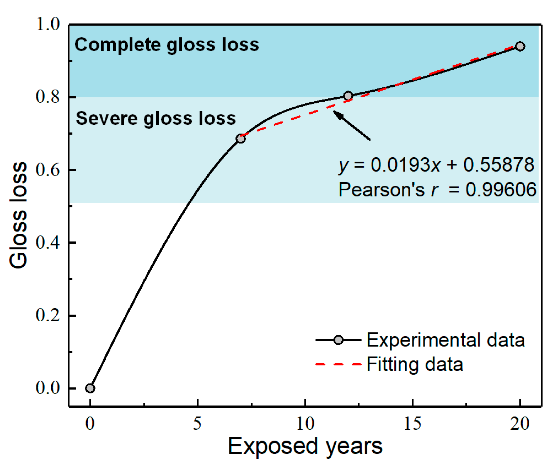
Figure 4 shows the curve of the loss of gloss of the epoxy-coated aluminum alloy specimens subjected to different durations of exposure. According to ISO 4268-1 [26], the process of aging of a coating can be divided into three stages. When the loss of gloss is less than 50%, it can be considered a stage of slight gloss loss. After seven years of exposure, the gloss loss of the epoxy coating was 68.6%, at grade 4, which is the stage of severe gloss loss. After 12 years of exposure, the gloss loss was 80.3%, which is considered complete gloss loss, at a grade of 5. After 20 years of exposure, the gloss loss was 93.7%, possibly because the indoor environment could not block ultraviolet radiation and the photoaging effect of the coating had gradually accumulated due to prolonged exposure. In addition to the high temperature, humidity, and chlorine ion content of the air, the surface film of the coating accelerated its decomposition, and the hydrolysis of the epoxy resin intensified. After exposure for 7, 12, and 20 years, the gloss loss on the surface of the coating could be approximately regarded as a linear growth, with a linear correlation coefficient of 0.996. Because the epoxy primer-coated specimens were in the stage of severe gloss loss after seven years of exposure, the main stage of gloss loss had occurred before this. Moreover, due to salt particles and the deposition of sand on the surface in the initial stage of exposure, the gloss of the coating decreased rapidly. After seven years of exposure, due to the balance between the photoaging effect and cross-linking reaction of the coating surface, the generation of the products of corrosion, and hydrolysis of the coating substrate, the gloss exhibited steady degradation.
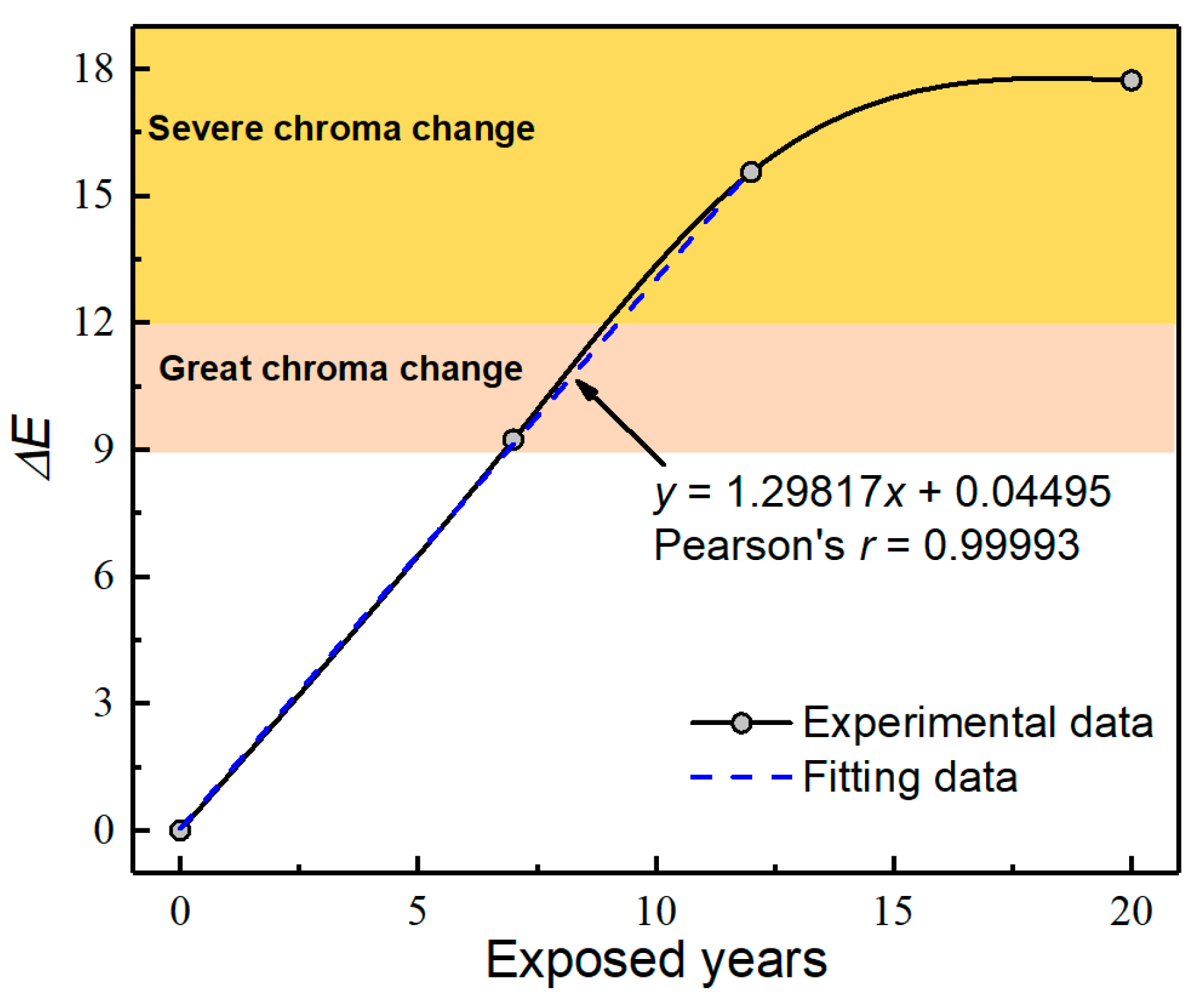
Figure 5 shows the curve of the variation in the off-color rate of the epoxy primer-coated specimens with different durations of exposure. According to ISO 4268-1 [26], the off-color rate of epoxy primer-coated specimens can be divided into three stages. When the off-color rate is below 9, it can be regarded as a slight discoloration. After seven years of exposure, the off-color rate of the epoxy primer-coated specimen was 9.24 and its chroma change grade was four. After 12 and 20 years of exposure, the off-color rates were 15.56 and 17.73, respectively, with a chroma change grade of five, which signifies the stage of a severe change in color. Before 12 years of exposure, the difference in the chroma of the epoxy primer-coated specimens showed a linear increase, with a linear correlation coefficient of 0.999. With an increase in the duration of exposure, the speed of chroma change gradually decreased, and finally tended to a stable value. This might have occurred because, in the initial stage of aging due to corrosion, the photodegradation of the coating surface generated chromophores. Due to the exposure of pigment particles, the chroma changed prominently. In the later stage of corrosion-induced aging, the aluminum alloy substrate corroded. At this time, the hydrolysis of the pigment particles reached an equilibrium such that the chroma of the coatings did not change, and tended to be stable. The main stage of discoloration occurred 12 years before exposure.
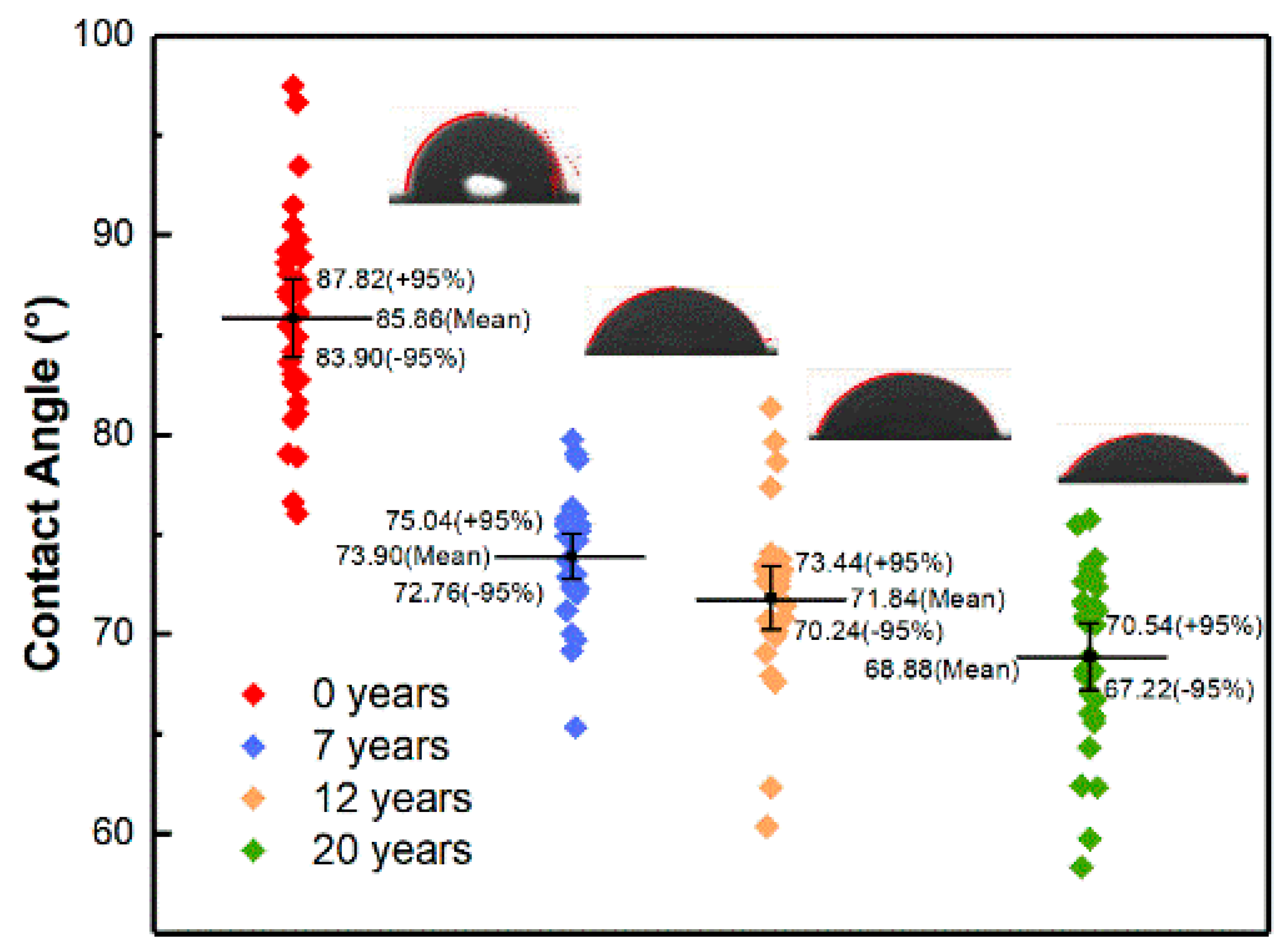
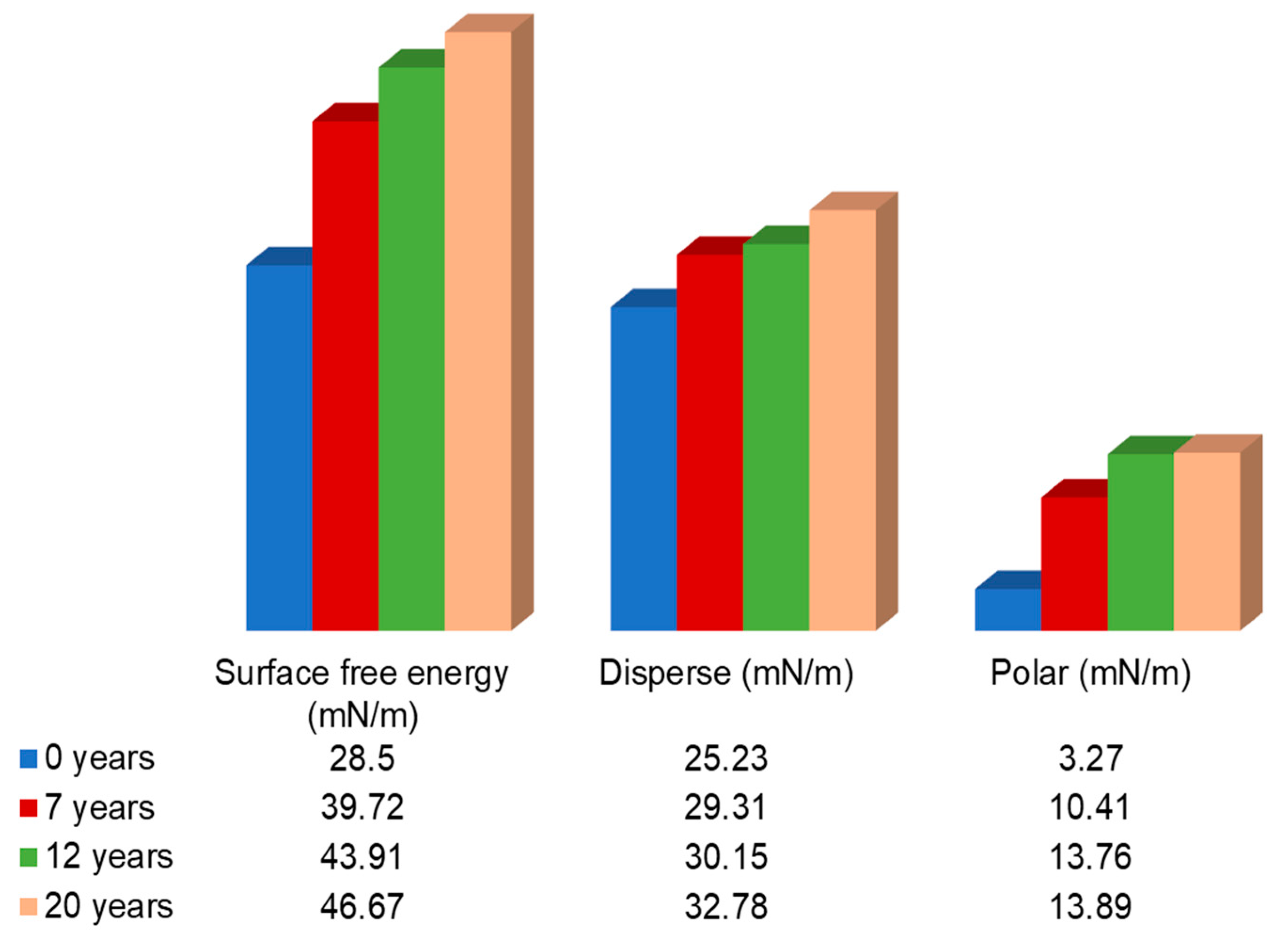
The contact angles of the unexposed epoxy primer-coated specimens, as well as those exposed for 7, 12, and 20 years, were measured. Thirty locations for each specimen were selected for the measurements, and the results are shown in Table 3. The Kolmogorov–Smirnov test was performed on the results [27]. The approximate associated probability values (bilateral progressive significance level) of specimens exposed for 0, 7, 12, and 20 years were 0.203, 0.201, 0.077, and 0.144, respectively, all greater than the significance level of 0.05. Therefore, the data for the epoxy primer-coated specimens with different durations of exposure met the normal distribution [28]. Figure 6 shows a scatter interval plot of the contact angles of the epoxy primer-coated specimens exposed for different durations, as well as the measured mean values of the contact angles at a 95% confidence interval. Figure 7 shows the surface free energy, dispersion, and polarization of epoxy primer-coated specimens exposed for different numbers of years. It is clear that in the initial stage of corrosion, the average contact angle decreased significantly from 85.86° to 73.90°. After seven years of exposure, the decline in the contact angle gradually flattened out, possibly because the aging of the epoxy coatings produced hydrophilic groups that enhanced the wettability of the surface. As the duration of exposure increased, the damage to the coating surface provided a channel for corrosive ions to infiltrate. The aluminum alloy substrate then corroded, and the organic coating tended to saturate due to hydrolysis.
The free energy γ of the solid surface, including the polar component (γp) and the dispersion component (γd), as well as the relationship between them is shown in Equations (3) and (4) [29]. The polarity component of the surface energy of the coating increased with an increase in the duration of exposure, which indicates that polar groups were generated during the aging and degradation of the epoxy coatings. The component of energy dispersion of the coating surface also increased, which indicates that its aging and degradation caused the epoxy resin to break the bonds, and promoted the cross-linking reaction that increased the surface density of the coating.
W S L a = γ L ( 1 + cos θ )
W S L a = 2 ( γ S d γ L d ) 1 / 2 + 2 ( γ S p γ L p ) 1 / 2
where γ, γp, and γd represent the free energy, dispersion, and polarization on the surface, respectively, S and L represent solid and liquid, respectively, θ is the contact angle, and W S L a is the adhesion work.

3.1.2. SEM Analysis of Micro-Defects on the Surface

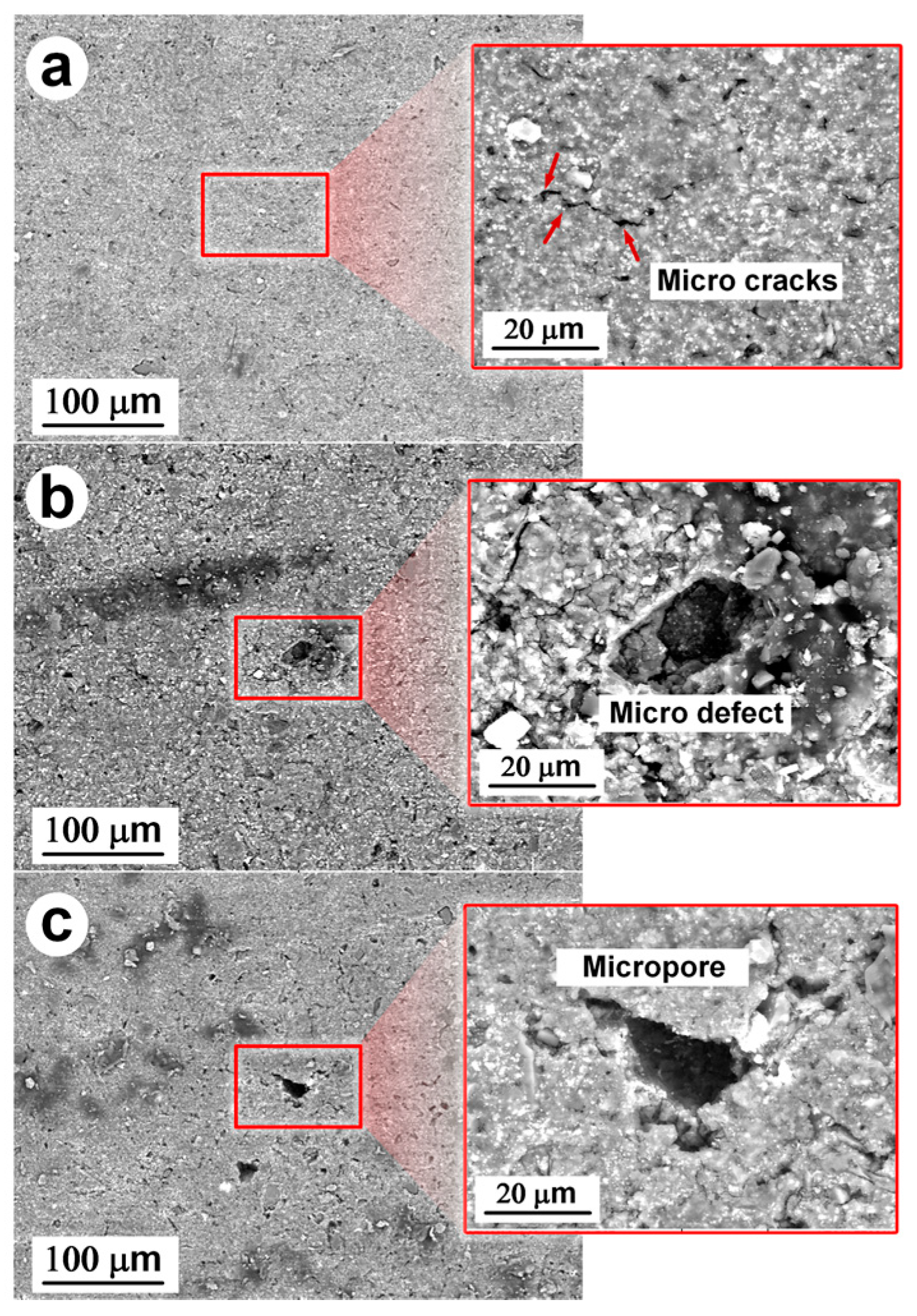
The surface morphologies of the intact areas of the epoxy primer-coated aluminum alloy specimens exposed for 7, 12, and 20 years, as obtained by SEM, are shown in Figure 8a–c. It is clear that with an increase in the duration of exposure, defects on the surface of the specimens gradually increased and the depth of the micropores gradually deepened. After 12 years of exposure, micro-pits began to form on the surface of the specimens but were not very deep, as shown in the local magnified figure. This might have occurred owing to the gradual pulverization of the surface of the epoxy coatings in the initial stage of the exposure test, which led to the surface cracking due to the generation of the products of aging and hydrolysis. Chlorine and nitrate ions infiltrated through channels formed in the micro-cracks, gradually eroding the anodic oxidation film under the epoxy coating [30]. Micro-cracks on the surface of the epoxy coatings expanded due to the accumulation of the products of corrosion. When corrosive ions began to erode the aluminum alloy substrate, the rate of generation of the products of corrosion accelerated, which caused the channel to continuously expand, and led to the deepening of the corrosion pits [31].
Image Pro Plus6.0 software was used to calculate the percentage of the regions of defect (micro-surface holes) in the macroscopically visible intact area of the surface coating of the specimens subjected to different durations of exposure, and binarization was carried out. The results are shown in Figure 9. It is evident that the mean percentage of the regions of defect in the macroscopically visible intact area of the surface coatings increased with the duration of exposure; it was 7.21% after exposure for 20 years. Only a few cracks emerged on the surface owing to the high density of the coatings in the first seven years of exposure, because of which the growth rate of the area of defect was slow. After 7–12 years of exposure, the rate of aging and corrosion accelerated due to the generation of pitting from the extension of the micro-defects. After exposure for 20 years, the rates of aging and corrosion began to slow down as the pits deepened and the corrosive ions infiltrated into the aluminum substrate.

3.1.3. Fractal Characteristics of Surface Corrosion

Because the area of corrosion of the epoxy primer-coated specimens was a 2D plane closed area, as shown in Figure 3 and Figure 8, its boundary formed a closed curve. The fractal dimension of regions of the surface corrosion of the specimens was obtained by slit island method [32]. The principle is to estimate the fractal dimension D according to the relationship between perimeter L(ε) and area A(ε), as shown in Equation (5) [33]:
α D ( ε ) = L 1 D ( ε ) A 1 2 ( ε )
where ε is the measurement yardstick, ε = η L 0 , η is the absolute measurement yardstick, and L0 is the initial circumference of the island.
αD(ε) relates to only the measurement yardstick, and is independent of the actual size of the island. To avoid having to calculate the value of the measurement yardstick, we assumed that the graphs of islands of different sizes were statistically similar. In other words, that their perimeters and areas have fractal characteristics under a specific measurement yardstick. Therefore, Equation (5) can be simplified as follows:
lg L = constant + D 2 lg A
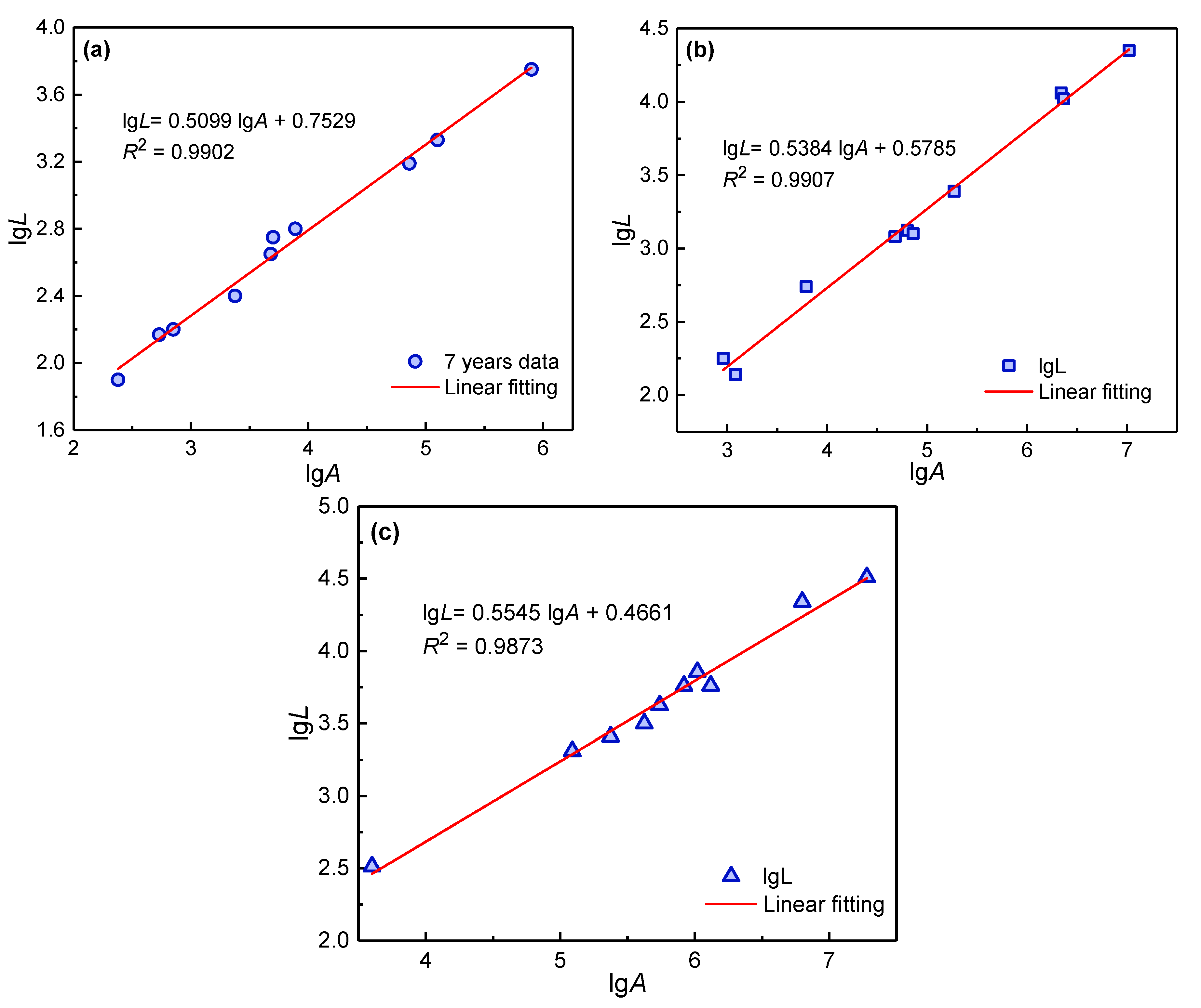
The perimeter and area of corrosion, as well as the regions of aging on the surface of specimens of the epoxy-coated aluminum alloy 7075-T6 exposed for 7, 12, and 20 years, were measured by using HiRox’s RH-8800 digital video microscope (Gaoxiong, China). Ten corrosion regions were randomly selected on each specimen exposed for different durations. The measured perimeter L and area A data were plotted logarithmically, and the least-square method was used for linear fitting. The results are shown in Figure 10.
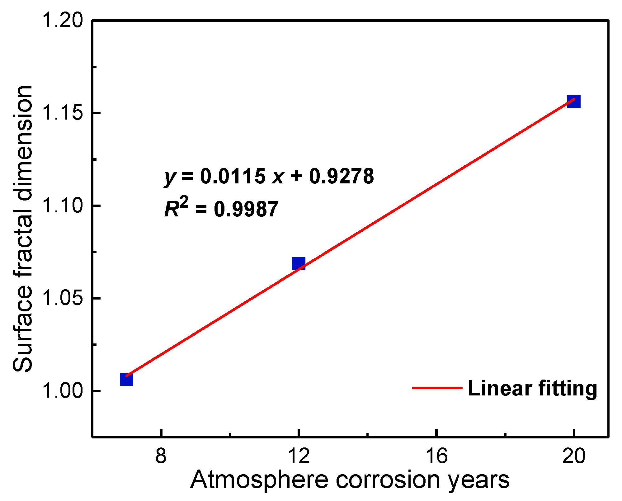
As is apparent from the results of linear fitting in Figure 10, a high linear correlation was obtained between lg L and lg A, and the correlation coefficient of fitting R2 was greater than 0.987. This indicates that the regions of surface corrosion of the epoxy primer-coated specimens had clear statistical fractal characteristics under different durations of exposure. The surface fractal dimension of the regions of surface corrosion of the epoxy primer-coated specimens was obtained by Equation (6), as shown in Figure 11. The fractal dimensions of the regions of surface corrosion were all between 1 and 1.2, and increased linearly with an increase in the duration of exposure. This indicates that the morphology of corrosion of the surface of the epoxy primer-coated specimens became more complex with an increase in the duration of corrosion.
Note: We note that a shorter conference version of part 3.1.3 appeared in S. Zhang and Y. T. He (2018). Our initial conference paper did not address the problem of mechanism of corrosion and aging of the epoxy coatings. This manuscript addresses this issue and provides additional analysis using more data and the overall image reconstruction quality. The previous conference paper published by the author is Sheng Zhang, Yuting He, Teng Zhang, etc. Study on atmospheric corrosion damage of aviation aluminum alloy coating system based on fractal theory[C]. The 5th Congress on Marine Materials and Corrosion Protection, Zhuhai, 2018.

3.1.4. AFM Analysis of Surface Morphology

The morphologies of the epoxy primer-coated aluminum alloys exposed for different numbers of years are shown in Figure 12. After exposure for seven years, the surface of the epoxy coating was unevenly distributed, with some bumps and cracks. The area occupied by bulges and cracks was large, possibly due to the unbalanced osmotic pressure caused by the hydrolysis of the products of aging on the surface of the epoxy coating [34]. After exposure for 12 years, the surface roughness (Ra) had increased from 55.1 nm to 165 nm, mainly because the surface aging of the epoxy coating was more significant, and its surface roughness increased due to an increase in the products of aging and hydrolysis. After exposure for 20 years, the surface roughness of the epoxy coating decreased to 118 nm, possibly because its post-curing effect intensified the cross-linking reaction of the functional groups and caused the distribution of the products of aging and hydrolysis on the surface to become more uniform [35]. Deep micropores appeared on the surface, indicating that the coating had failed, and corrosive ions had infiltrated into the matrix along micropores on the surface.

3.2. Sectional Characterization

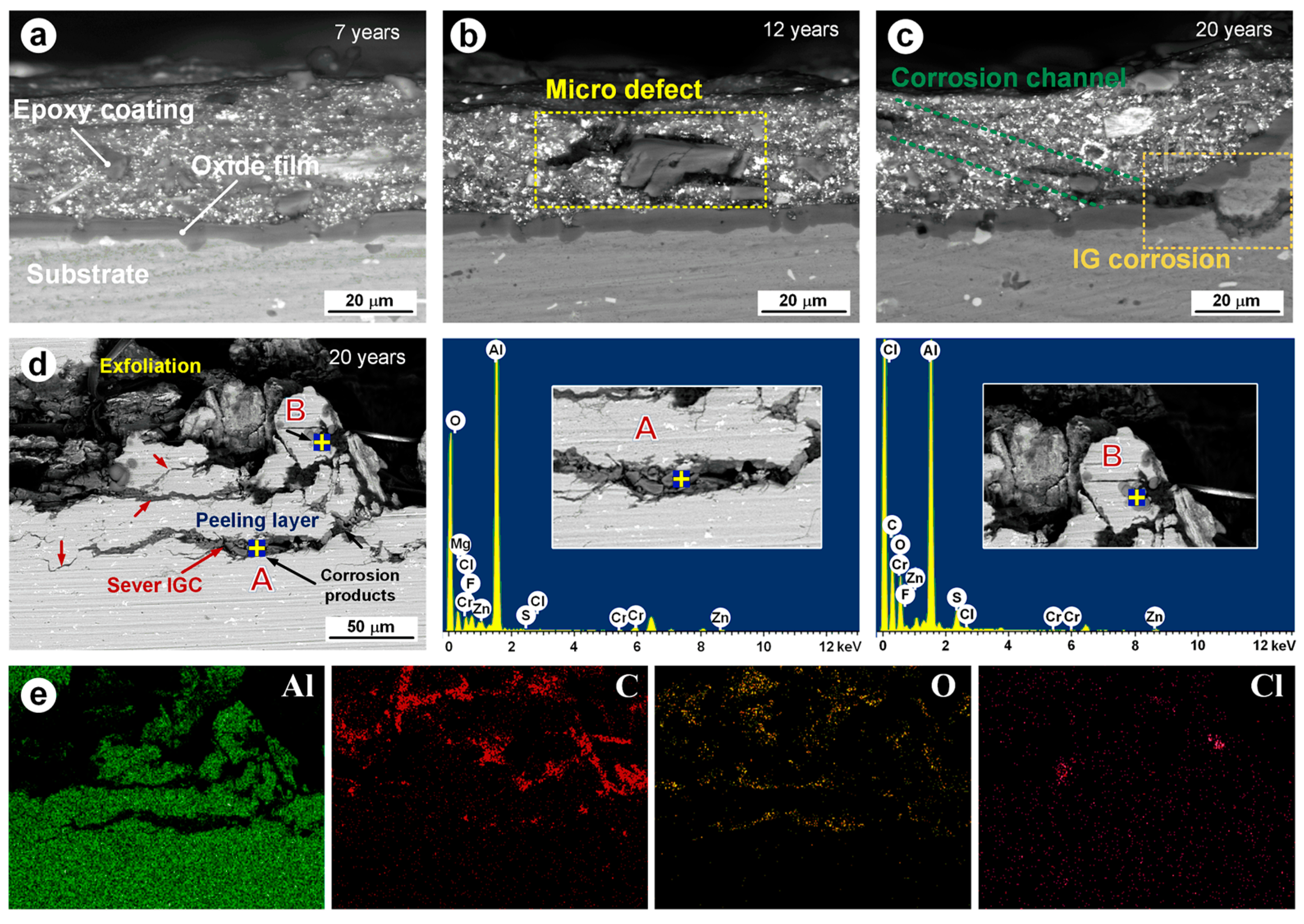
Figure 13 shows the cross-sectional morphology and energy spectra of the epoxy primer-coated aluminum alloy exposed for different numbers of years. It is clear from Figure 13a that after seven years of exposure, the epoxy coating was bonded well to the anodic oxidation film, and no cracking had occurred. As shown in Figure 13b, many significant defects appeared on cross-sections of the epoxy coating after exposure for 12 years. After exposure for 20 years, transport channels for corrosive ions were formed by cracks on the epoxy coating, which corroded the anodic oxidation film and caused the intergranular corrosion (IGC) of the aluminum substrate. The area where the epoxy coatings on the specimen had peeled after exposure for 20 years was analyzed, as shown in Figure 13d. Severe intergranular corrosion appeared on the aluminum substrate and exfoliated corrosion appeared on its intermediate layer. By analyzing the composition of the products of corrosion at point A, we noted that the amounts of Al and O were high. This might have occurred because the substrate was in a state of passivation after local pitting, and the precipitated phase (Al−Cu−Fe−Mn−Si), with a higher electrochemical potential relative to the aluminum substrate, was used as the cathode for the oxygen uptake reaction (Equation (7)). The Al at the bottom of the corrosion pit was dissolved as an anode into Al3+ (Equation (8)), and was combined with the OH formed by the cathode to form the product of corrosion, Al(OH)3 [31]. By analyzing the elemental composition of point B and combining this with the result of the EPMA, as shown in Figure 13e, it is evident that the concentration of Cl was high. This might have been the case because the deposition of the products of corrosion can lead to the formation of blocked batteries. To maintain the charge balance in the hole, Cl permeated into it, and an increase in its concentration caused the reaction shown in Equations (10) and (11) [30].
O 2 ( g ) + 2 H 2 O + 4 e 4 OH ( aq )
Al Al 3 + + 3 e
Al 3 + + H 2 O + Cl Al ( OH ) Cl + + H +
2 Al + 6 H + 4 Cl 3 H 2 + 2 AlCl 2 +
Al ( OH ) Cl 2 + Cl AlCl 3 + OH

3.3. Electrochemical Characterization

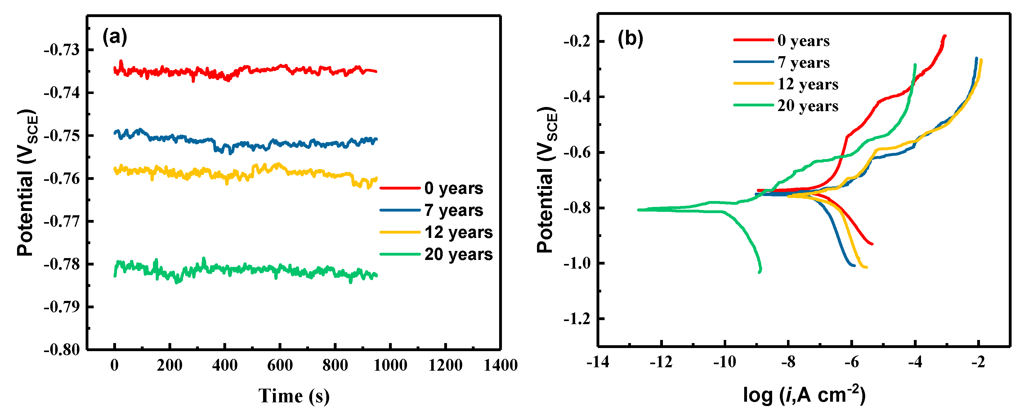
The measured results of OCP values and polarization curves are shown in Figure 14, and the relevant electrochemical corrosion parameters are shown in Table 4. Figure 14a shows that the OCP values of each sample stabilized after 16 min of testing, and the values of unexposed samples were more positive than that of exposed sample.
Figure 14b shows the polarization curves measured for the different samples. The cathodic branch and the anodic branch of the curves corresponded to the oxygen reduction reaction and the active dissolution reaction, respectively, of the aluminum alloy. According to ref. [36], the corrosion current density (icorr) of each sample can be determined via extrapolation of the Tafel slope. Furthermore, the corrosion rate (CR; μm/year) of the aluminum alloy was calculated in accordance with Faraday’s law ref. [37] and ref. [38]:
CR = 10.89·icorr
The values of Ecorr, icorr, and CR were calculated for the samples under different years of exposure (see Table 4). As the table shows, the Ecorr values of unexposed samples were more positive than those of exposed samples. The anode Tafel line of the unexposed sample is steeper, possibly because the aluminum alloy has been passivated, and the sample exposed to atmospheric corrosion may have been previously passivated. The corrosion potential and corrosion current density increased with the increase in exposure years. The CR value was also increasing. After 20 years of corrosion, the CR values increased 5.2-fold.
The electrochemical measurements of the epoxy primer-coated aluminum alloys exposed for 7, 12, and 20 years are shown in Figure 15. As shown in Figure 15a, the impedance of the specimens was significantly reduced owing to the long-term exposure. After seven years of exposure, the impedance of the epoxy coatings was still high, and protected the substrate to some extent. However, after 12 years of exposure, the impedance had been reduced to 6.53 × 10⁵ Ω cm2, and it lost its protective effect on the substrate. After 20 years of exposure, the impedance of the epoxy coatings had increased to 2.56 × 10⁶ Ω cm2, possibly owing to the increased cross-linking reaction caused by post-curing in the late corrosion-based aging of the epoxy coatings, but this does not indicate that the corrosion resistance of the epoxy coatings had increased. As shown in Figure 15b, after exposure for 20 years, the phase angle was negative, which indicates that the aluminum substrate had corroded and the epoxy coating had failed.
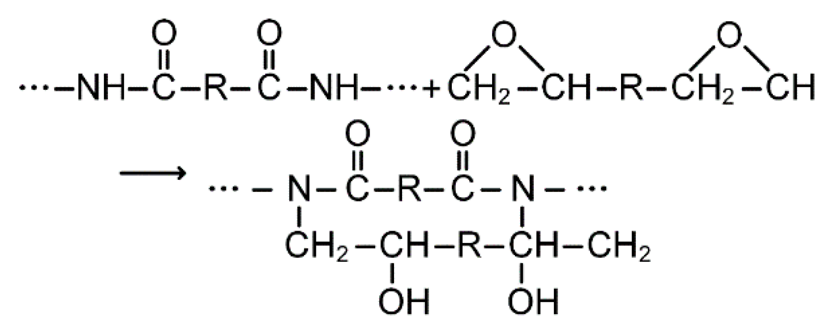
Different equivalent circuit models were needed for fitting because the epoxy-coated specimens exposed for different periods exhibited different characteristics of aging due to corrosion. The equivalent circuit diagram of the results of the electrochemical impedance test and the mechanism of corrosion-induced aging of the epoxy-coated aluminum alloy are shown in Figure 16. The corresponding components of the equivalent circuit were as follows: Rs is the resistance of the solution, Rc is the resistance of the epoxy coating, Qc is its capacitance, W is the Warburg impedance, Rof is the charge transfer resistance of the reaction of the anodic oxidation film, Qof is the capacitance of the interface of the anode oxidation film, Rct is the charge transfer resistance of the corrosion of the aluminum alloy substrate, Cdl is the interfacial double-layer capacitance of corrosion of aluminum alloy substrate, and L and RL are the inductance and the resistance to inductance generated by the corrosion of the aluminum alloy substrate, respectively. Inductance is often caused by the accumulation of the products of corrosion around the electrode [35,39]. Because the frequency response of the anodic oxidation film is not that of a pure capacitor, the constant phase angle element Q (CPE) was used instead of C [3,40,41,42]. As shown in Figure 15b, the curve of the unexposed epoxy-coated specimen had two time constants, representing the epoxy coating and the anodic oxidation film of the double-layer protective system, respectively. These two time constants appeared in the curve of the epoxy-coated specimens after 7 and 12 years of exposure. Because the substrate of the specimen had not corroded at this time, and the characteristics of the Warburg impedance appeared in the middle-frequency band, as shown in Figure 15a, and the circuit model could be fitted according to Figure 16b. This stage was the control process of H2O and O2. A large number of aging products were generated on the surface of epoxy coating due to the breaking of its main chains, as shown in Figure 17 [34]. The yellow zinc pigment was hydrolyzed, as shown in Figure 18, resulting in a large number of hydrolyzed products. Because small cracks and pores formed in the outer layer of the anodic oxidation film, the electrolyte easily penetrated into it, because of which Qc was directly connected to the matrix [43]. The curve of the epoxy-coated specimens exposed for 20 years had three time constants, and the phase angle of the low-frequency region was negative, indicating that the aluminum alloy substrate had corroded. The three time constants corresponded to the resistance of the epoxy coating, the dissolution of the anodic oxidation film, and the corrosion of the aluminum alloy substrate. At this stage, owing to the intensified post-curing effect of the coating, the cross-linking reaction of functional groups played a dominant role in the corrosion-induced aging process, as shown in Figure 19 [21,44].
The curves of resistance Rc and capacitance Qc of the epoxy coatings exposed for different durations were compared, as shown in Figure 20. It is clear that the resistance of the epoxy coatings dropped from 108 to 105 Ω·cm2 with increasing duration of exposure. However, after 20 years of exposure, a slight increase was noted. As shown in the change of coating capacitance, the capacitance of the epoxy coating rose to 10−6 F·cm−2 in the first 12 years, but decreased slightly after 20 years of exposure. This might have occurred owing to the intensified post-curing effect of the epoxy coatings and the relatively uniform surface formed by the cross-linking of small groups. However, at this time, the substrate began to corrode, because of which the epoxy coating was ineffective.

3.4. Aging Characteristics of Coatings

3.4.1. TGA and DSC analysis

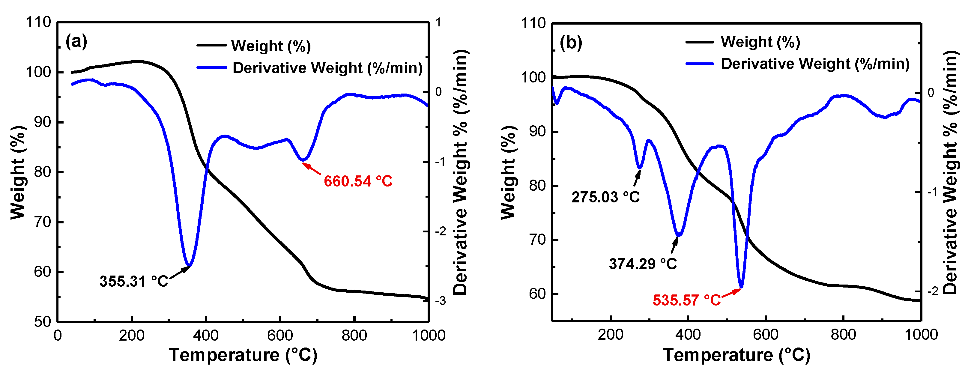
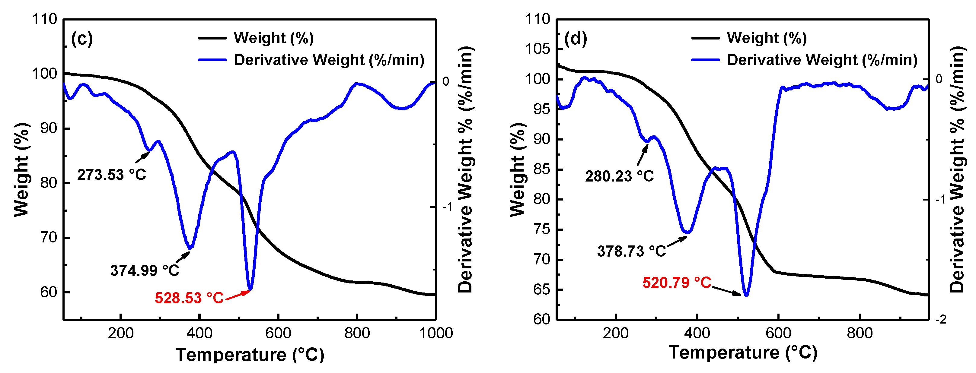
To further analyze the influence of corrosion-induced aging on the thermal properties of the epoxy coatings, TGA and DSC analyses were carried out. The weight loss and glass transition temperature of the epoxy coatings under different durations of exposure were obtained, and were used to characterize their degrees of cross-linking in the corrosion and aging processes [40,44]. Figure 21 shows the TGA–DTA curves of the coatings under different durations of exposure. The DTA curves in Figure 21 show that the unexposed epoxy coating had two peaks, representing two weightlessness stages. The first stage corresponded to the decomposition of glassy water molecules and water obtained due to crystallization, whereas the second stage corresponds to the removal of their functional groups [45,46]. The stage of maximum weightlessness was the first, and might have occurred because the surface of the unaged epoxy coatings had not yet generated a large number of hydrophilic groups [47]. After long-term atmospheric corrosion and aging, the epoxy coating exhibited additional weight loss at 270–280 °C due to the products of aging generating on the surface containing crystalline water [48]. By comparing the rate of weight loss and the corresponding temperature in the main chain cracking stage of the epoxy coatings under different durations of exposure, we found that weight loss decreased with duration. Moreover, the temperature of weight loss decreased, from an initial temperature of 660.54 °C to 535.57 °C, after exposure for seven years. This indicates that the effects of corrosion and aging on the epoxy coatings may be concentrated in the first seven years. After seven years of exposure, the temperature of weightlessness gradually decreased, indicating that the degree of cross-linking on the surface of the epoxy coatings had gradually increased.
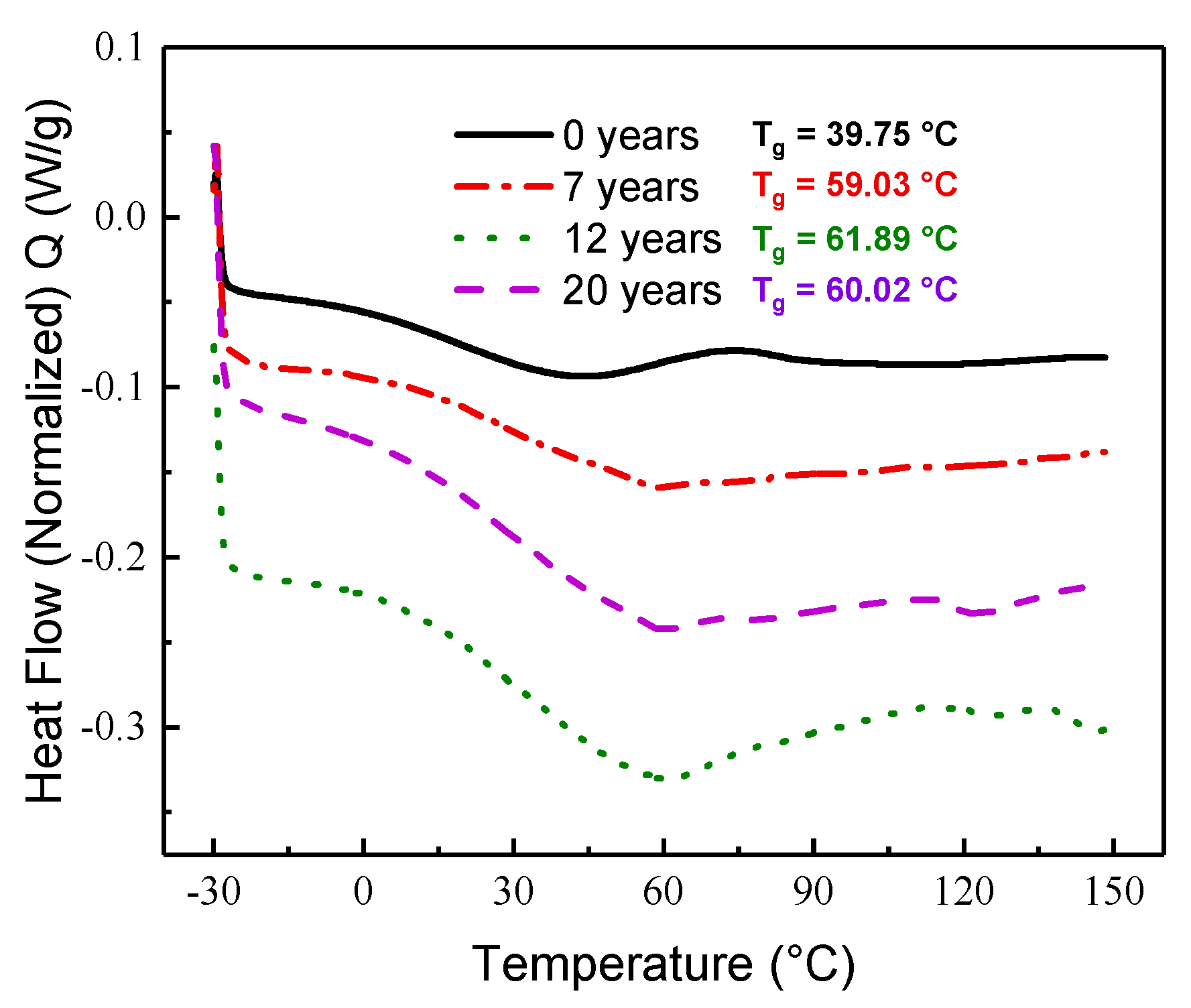
Figure 22 shows the DSC curve of the epoxy coatings under different durations of exposure. It is clear that the glass transition temperature Tg of the unexposed epoxy coating was 39.75 °C, lower than the value after long-term atmospheric aging and corrosion. This indicates that corrosion and aging may increase the degree of cross-linking and increase the brittleness of the epoxy coating. The glass transition temperature Tg was 60.02 °C after exposure for 20 years, slightly higher than the value of the samples exposed for 12 years. This indicates that the corrosion and aging of the epoxy coatings was a combination of degradation due to aging and the post-curing process after long-term atmospheric exposure.

3.4.2. XPS analysis

XPS analysis was performed on the chemical composition of the epoxy coatings under different durations of exposure, and peak fitting was performed on the main elements, C1s and O1s. The results are shown in Figure 23. Those for C1s can be divided into four characteristic peaks, located at 289.3, 286.5, 285.2, and 284.9 eV. They represent the bonds O−C=O, C−O−C, C−N, and C−C/C−H/C=C, respectively [46,47,48]. The results for O1s can also be divided into four characteristic peaks, located at 534.1, 533.2, 532.5, and 531.8 eV. They represent the bands O−C=O, N−C=O, O−H, and N−C−O, respectively [49,50,51]. As shown in Figure 23b,d, the content of N−C=O and C−C/C−H/C=C decreased after 12 years of exposure owing to the small number of amino radicals and carboxyl molecules generated by the fracture of the main chain of the epoxy resin. This increased the content of N−C−O and C−N [52,53]. As shown in Figure 22f, the contents of N−C=O and C−C/C−H/C=C increased while those of N−C−O and C−N decreased after exposure for 20 years. This might have occurred because of the small number of amino radicals forming on the surface cross-link with other groups to produce new functional groups, owing to the post-curing effect of the epoxy coatings [54,55]. The soluble or volatile debris generated by the aging of the epoxy coatings flowed outside the surface, releasing internal stress, and increasing osmotic pressure; thus, the surface of epoxy coating became more convex and fold [34,56].

4. Conclusions

The results of our study can be summarized as follows:
(1)
By measuring the chroma, gloss, and contact angle of epoxy coatings exposed to the atmosphere in the long term, we found that different durations of exposure induce different characteristics of aging. The island method was used to calculate the fractal characteristics of corrosion on the surface of the coatings. The number of fractal dimensions increased with the duration of exposure. AFM was used to analyze the micro-morphology and roughness of the coating surface, and showed that the surface roughness increased gradually in the first 12 years, but decreased after 20 years of exposure.
(2)
After 20 years of exposure, the transport channels of corrosive ions appeared in the cross-section of the epoxy coating, resulting in the intergranular corrosion of the substrate. Significant intergranular corrosion and exfoliation corrosion occurred in the area where the coating had peeled, and the product of corrosion was Al(OH)3—as determined by EDS and XRD. With the increase in the corrosion years, the CR values representing the corrosion kinetic parameters also increased continuously, and the CR values increased by 5.2-fold compared with the uncorroded sample after 20 years of exposure.
(3)
TGA and DSC analyses of the epoxy coatings showed that the weight loss decreased with the duration of exposure. The glass transition temperature Tg after exposure for 20 years was slightly higher than that exposed for 12 years. The components of the coating, as analyzed by XPS, showed that after 12 years of exposure, the contents of N−C=O and C−C/C−H/C=C decreased. After 20 years of exposure, the contents of N−C=O and C−C/C−H/C=C increased.

Author Contributions

Conceptualization, T.Z. (Tianyu Zhang) and T.Z. (Teng Zhang); methodology, S.Z.; validation, Y.H., T.Z. (Tianyu Zhang) and T.Z. (Teng Zhang); formal analysis, T.Z. (Tianyu Zhang); investigation, B.M. and Z.G.; writing—original draft preparation, T.Z. (Tianyu Zhang); writing—review and editing, T.Z (Teng Zhang) and B.M.; supervision, Y.H.; funding acquisition, Y.H. All authors have read and agreed to the published version of the manuscript.

Funding

This research was funded by the National Defense Pre-Research Foundation of China (61409220202), the National Natural Science Foundation of China (52005507), the Youth Science Foundation program (52007197), and the Supported Fund for Excellent Doctoral Dissertation of Air Force Engineering University (KGD082520001).

Data Availability Statement

All data included in this study are available upon request by contact with the corresponding author.

Conflicts of Interest

The authors declare no conflict of interest.

Abbreviations

The formula symbols and their meanings in the article.
SymbolsMeaning
GLthe loss of gloss
G0the gloss of the specimen without corrosion and aging
Gthe gloss of the specimen after several years of exposure
Ethe chroma
Lthe shade of the color
athe red–green direction
bthe yellow–blue direction
γthe free energy on the surface
γpdispersion on the surface
γdpolarization on the surface
Ssolid
Lliquid
θcontact angle
W S L a adhesion work
εmeasurement yardstick
ηabsolute measurement yardstick
L0initial circumference of the island
αD(ε)measurement yardstick
Lmeasured perimeter
Ameasured area
Ecorrcorrosion potential
icorrcorrosion current density

References

  1. Yu, M.; Liu, J.H.; Li, S.M. Corrosion Protection and Detection Methods for Aeronautical Aluminum Alloy; Science Press: Beijing, China, 2017. [Google Scholar]
  2. Morsch, S.; Lyon, S.; Gibbon, S.R. The degradation mechanism of an epoxy-phenolic can coating. Prog. Org. Coat. 2017, 102, 37–43. [Google Scholar] [CrossRef] [Green Version]
  3. Katayama, H.; Kuroda, S. Long-term atmospheric corrosion properties of thermally sprayed Zn, Al and Zn–Al coatings exposed in a coastal area. Corros. Sci. 2013, 76, 35–41. [Google Scholar] [CrossRef]
  4. Liu, Y.; Wang, Z.; Ke, W. Study on influence of native oxide and corrosion products on atmospheric corrosion of pure Al. Corros. Sci. 2014, 80, 169–176. [Google Scholar] [CrossRef]
  5. Melchers, R.E. Bi-modal trend in the long-term corrosion of aluminium alloys. Corros. Sci. 2014, 82, 239–247. [Google Scholar] [CrossRef]
  6. Zhang, S.; Zhang, T.; He, Y.; Du, X.; Ma, B.; Zhang, T. Long-term atmospheric pre-corrosion fatigue properties of epoxy primer-coated 7075-T6 aluminum alloy structures. Int. J. Fatigue 2019, 129, 105225. [Google Scholar] [CrossRef]
  7. Qiao, C.; Shen, L.; Hao, L.; Mu, X.; Dong, J.; Ke, W.; Liu, J.; Liu, B. Corrosion kinetics and patina evolution of galvanized steel in a simulated coastal-industrial atmosphere. J. Mater. Sci. Technol. 2019, 35, 2345–2356. [Google Scholar] [CrossRef]
  8. Sun, S.; Zheng, Q.; Li, D.; Hu, S.; Wen, J. Exfoliation corrosion of extruded 2024-T4 in the coastal environments in China. Corros. Sci. 2011, 53, 2527–2538. [Google Scholar] [CrossRef]
  9. Sun, S.; Zheng, Q.; Li, D.; Wen, J. Long-term atmospheric corrosion behaviour of aluminium alloys 2024 and 7075 in urban, coastal and industrial environments. Corros. Sci. 2009, 51, 719–727. [Google Scholar] [CrossRef]
  10. Cao, C.N. Principles of Electrochemistry of Corrosion; Chemical Industry Press: Beijing, China, 2004. [Google Scholar]
  11. Bai, L.-J.; Kou, G.; Zhao, K.; Chen, G.-T.; Yan, F.-X. Effect of in-situ micro-arc oxidation coating on the galvanic corrosion of AZ31Mg coupled to aluminum alloys. J. Alloy. Compd. 2019, 775, 1077–1085. [Google Scholar] [CrossRef]
  12. Bano, H.; Mahmood, A.; Khan, M.I.; Kazmi, S.A. Synergistic Corrosion Mitigation Appraisal of Coal Tar Epoxy Duplex Coating System by Spectroscopic and Microscopic Techniques. Arab. J. Sci. Eng. 2014, 39, 6783–6791. [Google Scholar] [CrossRef]
  13. Bhargava, S.; Kubota, M.; Lewis, R.; Advani, S.G.; Prasad, A.K.; Deitzel, J. Ultraviolet, water, and thermal aging studies of a waterborne polyurethane elastomer-based high reflectivity coating. Prog. Org. Coat. 2015, 79, 75–82. [Google Scholar] [CrossRef] [Green Version]
  14. Farrier, L.M.; Szaruga, S.L. Sample preparation and characterization of artificially aged aircraft coatings for microstructural analysis. Mater. Charact. 2005, 55, 179–189. [Google Scholar] [CrossRef] [Green Version]
  15. Gao, Z.; Zhang, D.; Qiu, X.; Jiang, S.; Wu, Y.; Zhang, Q.; Li, X. The mechanisms of corrosion inhibition of hot-dip galvanized steel by vanadyl oxalate: A galvanic corrosion investigation supported by XPS. Corros. Sci. 2018, 142, 153–160. [Google Scholar] [CrossRef]
  16. Geng, M.; He, G.; Sun, Z.; Chen, J.; Yang, Z.; Li, Y. Corrosion Damage Mechanism of TiN/ZrN Nanoscale Multilayer Anti-Erosion Coating. Coatings 2018, 8, 400. [Google Scholar] [CrossRef] [Green Version]
  17. Bastarrachea, L.J.; Goddard, J.M. Self-healing antimicrobial polymer coating with efficacy in the presence of organic matter. Appl. Surf. Sci. 2016, 378, 479–488. [Google Scholar] [CrossRef] [Green Version]
  18. Jiang, M.-Y.; Wu, L.-K.; Hu, J.-M.; Zhang, J.-Q. Silane-incorporated epoxy coatings on aluminum alloy (AA2024). Part 2: Mechanistic investigations. Corros. Sci. 2015, 92, 127–135. [Google Scholar] [CrossRef]
  19. Jiang, M.-Y.; Wu, L.-K.; Hu, J.-M.; Zhang, J.-Q. Silane-incorporated epoxy coatings on aluminum alloy (AA2024). Part 1: Improved corrosion performance. Corros. Sci. 2015, 92, 118–126. [Google Scholar] [CrossRef]
  20. Ramezanzadeh, B.; Attar, M. Studying the corrosion resistance and hydrolytic degradation of an epoxy coating containing ZnO nanoparticles. Mater. Chem. Phys. 2011, 130, 1208–1219. [Google Scholar] [CrossRef]
  21. Liu, F.; Yin, M.; Xiong, B.; Zheng, F.; Mao, W.; Chen, Z.; He, C.; Zhao, X.; Fang, P. Evolution of microstructure of epoxy coating during UV degradation progress studied by slow positron annihilation spectroscopy and electrochemical impedance spectroscopy. Electrochim. Acta 2014, 133, 283–293. [Google Scholar] [CrossRef]
  22. Cao, C.N.; Zhang, J.Q. An Introduction to Electrochemical Impedance Spectroscopy; Science Press: Beijing, China, 2002. [Google Scholar]
  23. Li, X.G.; Du, C.W.; Dong, C.F. China Gateway to Corrosion and Protection, in: Atmospheric Environmental Factors (2015). Available online: http://data.ecorr.org/edata/01/0103/010301/01030101/index.html (accessed on 13 February 2021).
  24. ISO 8565 Metals and Alloys—Atmospheric Corrosion Testing—General Requirements; International Organization for Standardization: Geneva, Switzerland, 2011.
  25. Zhang, S.; He, Y.; Zhang, T.; Wang, G.; Du, X. Long-Term Atmospheric Corrosion Behavior of Epoxy Prime Coated Aluminum Alloy 7075-T6 in Coastal Environment. Materials 2018, 11, 965. [Google Scholar] [CrossRef] [PubMed] [Green Version]
  26. ISO 4268-1 Paints and Varnishes—Evaluation of Degradation of Coatings—Designation of Quantity and Size of Defects, and of Intensity of Uniform Changes in Appearance—Part 1: General Introduction and Designation System; International Organization for Standardization: Geneva, Switzerland, 2016.
  27. Mora-López, L.; Mora, J. An adaptive algorithm for clustering cumulative probability distribution functions using the Kolmogorov–Smirnov two-sample test. Expert Syst. Appl. 2015, 42, 4016–4021. [Google Scholar] [CrossRef] [Green Version]
  28. Aslam, M. Introducing Kolmogorov–Smirnov Tests under Uncertainty: An Application to Radioactive Data. ACS Omega 2019, 5, 914–917. [Google Scholar] [CrossRef] [Green Version]
  29. Żołek-Tryznowska, Z.; Prica, M.; Pavlović, Ž.; Cveticanin, L.; Annusik, T. The influence of aging on surface free energy of corona treated packaging films. Polym. Test. 2020, 89, 106629. [Google Scholar] [CrossRef]
  30. Zhang, S.; Zhang, T.; He, Y.; Feng, Y.; Du, X.; Ma, B.; Zhang, T. Effect of coastal atmospheric corrosion on fatigue properties of 2024-T4 aluminum alloy structures. J. Alloy. Compd. 2019, 802, 511–521. [Google Scholar] [CrossRef]
  31. Zhang, S.; Zhang, T.; He, Y.; Liu, D.; Wang, J.; Du, X.; Ma, B. Long-term atmospheric corrosion of aluminum alloy 2024-T4 in coastal environment: Surface and sectional corrosion behavior. J. Alloy. Compd. 2019, 789, 460–471. [Google Scholar] [CrossRef]
  32. Liang, Z.; Feng, Z.; GuangXiang, X. Comparison of Fractal Dimension Calculation Methods for Channel Bed Profiles. Procedia Eng. 2012, 28, 252–257. [Google Scholar] [CrossRef] [Green Version]
  33. Mandelbrot, B.B. The Fractal Geometry of Nature, 1st ed.; W.H. Freeman & Co: San Francisco, CA, USA, 1982. [Google Scholar]
  34. Cai, G.; Zhang, D.; Jiang, D.; Dong, Z. Degradation of fluorinated polyurethane coating under UVA and salt spray. Part II: Molecular structures and depth profile. Prog. Org. Coat. 2018, 124, 25–32. [Google Scholar] [CrossRef]
  35. Guan, F.; Zhai, X.; Duan, J.; Zhang, J.; Li, K.; Hou, B. Influence of sulfate-reducing bacteria on the corrosion behavior of 5052 aluminum alloy. Surf. Coat. Technol. 2017, 316, 171–179. [Google Scholar] [CrossRef]
  36. Trdan, U.; Grum, J. SEM/EDS characterization of laser shock peening effect on localized corrosion of Al alloy in a near natural chloride environment. Corros. Sci. 2014, 82, 328–338. [Google Scholar] [CrossRef]
  37. Zhao, J.; Frankel, G.; McCreery, R.L. Corrosion Protection of Untreated AA-2024-T3 in Chloride Solution by a Chromate Conversion Coating Monitored with Raman Spectroscopy. J. Electrochem. Soc. 1998, 145, 2258–2264. [Google Scholar] [CrossRef] [Green Version]
  38. Xu, X.; Liu, D.; Zhang, X.; Liu, C.; Liu, D. Mechanical and corrosion fatigue behaviors of gradient structured 7B50-T7751 aluminum alloy processed via ultrasonic surface rolling. J. Mater. Sci. Technol. 2020, 40, 88–98. [Google Scholar] [CrossRef]
  39. Yang, L.; Wan, Y.; Qin, Z.; Xu, Q.; Min, Y. Fabrication and corrosion resistance of a graphene-tin oxide composite film on aluminium alloy 6061. Corros. Sci. 2018, 130, 85–94. [Google Scholar] [CrossRef]
  40. Yuan, X.; Yue, Z.; Liu, Z.; Wen, S.; Li, L.; Feng, T. Comparison of the failure mechanisms of silicone-epoxy hybrid coatings on type A3 mild steel and 2024 Al-alloy. Prog. Org. Coat. 2016, 90, 101–113. [Google Scholar] [CrossRef]
  41. Liu, Y.; Zhou, X.; Lyon, S.B.; Emad, R.; Hashimoto, T.; Gholinia, A.; Thompson, G.E.; Graham, D.; Gibbon, S.R.; Francis, D. An organic coating pigmented with strontium aluminium polyphosphate for corrosion protection of zinc alloy coated steel. Prog. Org. Coat. 2017, 102, 29–36. [Google Scholar] [CrossRef] [Green Version]
  42. Tokutake, K.; Nishi, H.; Ito, D.; Okazaki, S.; Serizawa, Y. Relationship between degradation characteristics of organic coating on internal bottom plate of oil storage tank and constant-phase element parameter values. Prog. Org. Coat. 2015, 87, 69–74. [Google Scholar] [CrossRef]
  43. Ye, Z.; Liu, D.; Li, C.; Zhang, X.; Yang, Z.; Lei, M. Effect of Shot Peening and Plasma Electrolytic Oxidation on the Intergranular Corrosion Behavior of 7A85 Aluminum Alloy. Acta Met. Sin. (English Lett.) 2014, 27, 705–713. [Google Scholar] [CrossRef]
  44. Cai, G.; Wang, H.; Jiang, D.; Dong, Z. Degradation of fluorinated polyurethane coating under UVA and salt spray. Part I: Corrosion resistance and morphology. Prog. Org. Coat. 2018, 123, 337–349. [Google Scholar] [CrossRef]
  45. Liang, X.; Zhang, F.; Feng, W.; Zou, X.; Zhao, C.; Na, H.; Liu, C.; Sun, F.; Zhu, G. From metal–organic framework (MOF) to MOF–polymer composite membrane: Enhancement of low-humidity proton conductivity. Chem. Sci. 2012, 4, 983–992. [Google Scholar] [CrossRef]
  46. Zhao, G.; Wen, T.; Yang, X.; Yang, S.; Liao, J.; Hu, J.; Shao, D.; Wang, X. Preconcentration of U(vi) ions on few-layered graphene oxide nanosheets from aqueous solutions. Dalton Trans. 2012, 41, 6182–6188. [Google Scholar] [CrossRef]
  47. Shi, H.; Liu, F.; Yang, L.; Han, E. Characterization of protective performance of epoxy reinforced with nanometer-sized TiO2 and SiO2. Prog. Org. Coat. 2008, 62, 359–368. [Google Scholar] [CrossRef]
  48. Ji, W.-G.; Hu, J.-M.; Zhang, J.-Q.; Cao, C.-N. Reducing the water absorption in epoxy coatings by silane monomer incorporation. Corros. Sci. 2006, 48, 3731–3739. [Google Scholar] [CrossRef]
  49. Liu, J.; Liu, T.; Guo, Z.; Guo, N.; Lei, Y.; Chang, X.; Yin, Y. Promoting Barrier Performance and Cathodic Protection of Zinc-Rich Epoxy Primer via Single-Layer Graphene. Polymers 2018, 10, 591. [Google Scholar] [CrossRef] [PubMed] [Green Version]
  50. Lv, J.; Liang, T.; Chen, W. Comparison of corrosion behavior between coarse grained and nanocrystalline NiFe alloys in chloride solutions and proton exchange membrane fuel cell environment by EIS, XPS and Raman spectra techniques. Energy 2016, 112, 67–74. [Google Scholar]
  51. Lei, L.; Shi, J.; Wang, X.; Liu, D.; Xu, H. Microstructure and electrochemical behavior of cerium conversion coating modified with silane agent on magnesium substrates. Appl. Surf. Sci. 2016, 376, 161–171. [Google Scholar] [CrossRef]
  52. He, P.; Huang, M.; Fisher, S.; Yue, C.Y.; Yang, J. Effects of primer and annealing treatments on the shear strength between anodized Ti6Al4V and epoxy. Int. J. Adhes. Adhes. 2015, 57, 49–56. [Google Scholar] [CrossRef]
  53. Lin, B.; Zhou, S. Light-responsive nanoparticles with wettability changing from hydrophobicity to hydrophilicity and their application towards highly hydrophilic fluorocarbon coatings. Appl. Surf. Sci. 2015, 359, 380–387. [Google Scholar] [CrossRef]
  54. Li, L.; He, J.; Lei, J.; Xu, W.; Jing, X.; Ou, X.; Wu, S.; Li, N.; Zhang, S. A sol–bath–gel approach to prepare hybrid coating for corrosion protection of aluminum alloy. Surf. Coat. Technol. 2015, 279, 72–78. [Google Scholar] [CrossRef]
  55. Abel, M.-L.; Watts, J.F. Examination of the interface of a model adhesive joint by surface analysis: A study by XPS and ToF-SIMS. Surf. Interface Anal. 2009, 41, 508–516. [Google Scholar] [CrossRef] [Green Version]
  56. Watts, J.F.; Abel, M.-L.; Perruchot, C.; Lowe, C.; Maxted, J.T.; White, R.G. Segregation and crosslinking in urea formaldehyde/epoxy resins: A study by high-resolution XPS. J. Electron Spectrosc. Relat. Phenom. 2001, 121, 233–247. [Google Scholar] [CrossRef]
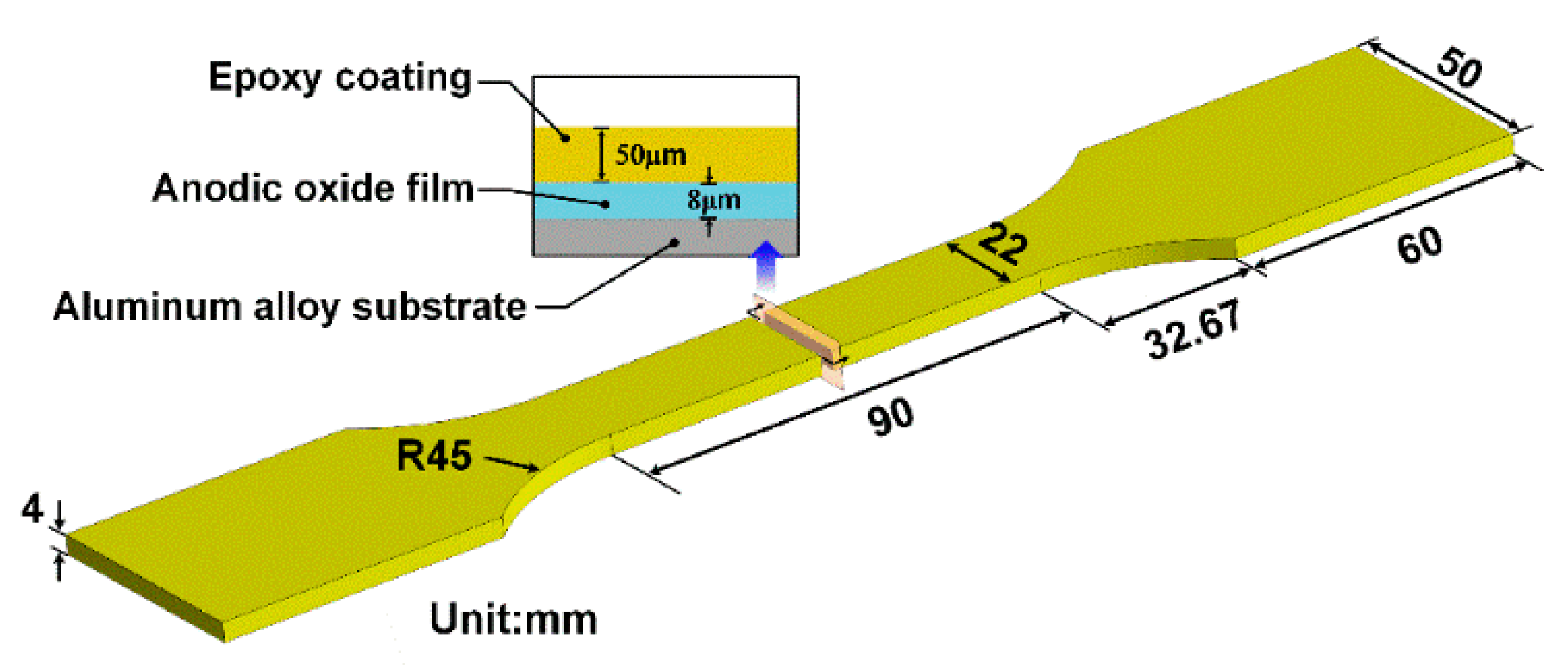
Figure 1. Schematic drawing of the epoxy-coated specimen. R45 refers to the radius of machining fillet at this point.
Coatings 11 00237 g001
Figure 2. Location of the coastal atmospheric exposure testing station and the indoor exposure testing shed: (a) location of Wanning Natural Environment Test Station; (b) ventilated rooms for atmospheric exposure tests.
Coatings 11 00237 g002
Figure 3. Analysis of the surface morphology and composition of the products of corrosion of epoxy primer-coated aluminum alloy exposed in the field. (ac) Surface morphology of specimens exposed for 7, 12, and 20 years. (d) XRD analysis of the products of corrosion in the area of exfoliation corrosion of the specimen exposed for 20 years.
Coatings 11 00237 g003
Figure 4. Gloss loss of the epoxy primer-coated specimens subjected to different durations of exposure.
Coatings 11 00237 g004
Figure 5. Off-color rate of epoxy primer-coated specimens subjected to different durations of exposure.
Coatings 11 00237 g005
Figure 6. Mean values and 95% confidence intervals of contact angles of epoxy primer-coated specimens exposed for different numbers of years.
Coatings 11 00237 g006
Figure 7. Surface free energy, dispersion, and polarization of epoxy primer-coated specimens exposed for different numbers of years.
Coatings 11 00237 g007
Figure 8. SEM micrographs of the surface of the intact area of the epoxy primer-coated specimens exposed for different durations: (a) 7 years, (b) 12 years, and (c) 20 years.
Coatings 11 00237 g008
Figure 9. Percentage of regions of defect in the macroscopically visible intact area of the surface coatings subjected to different durations of exposure.
Coatings 11 00237 g009
Figure 10. The relationship between the logarithmic perimeter (lg L) and the logarithmic area (lg A) of the regions of surface corrosion of specimens exposed for different durations, and the results of linear fitting: (a) 7 years; (b) 12 years; (c) 20 years.
Coatings 11 00237 g010
Figure 11. The surface fractal dimensions of the epoxy-coated specimens exposed for different numbers of years.
Coatings 11 00237 g011
Figure 12. 3D AFM morphologies, 2D AFM morphologies and height profiles of epoxy primer-coated aluminum alloys exposed for different numbers of years: (a) 7 years; (b) 12 years; (c) 20 years.
Coatings 11 00237 g012
Figure 13. Sectional SEM morphology and EDS analysis of epoxy primer-coated aluminum alloy after different numbers of years exposure: Sectional morphology of epoxy-coated specimen exposed for (a) 7 years, (b) 12 years, and (c) 20 years; (d) sectional morphology and EDS analysis of exfoliated area of epoxy-coated specimen exposed for 20 years; (e) electron probe microanalysis (EPMA) of exfoliated area of (d).
Coatings 11 00237 g013
Figure 14. (a) Typical open circuit potential and (b) polarization curves for the different specimens.
Coatings 11 00237 g014
Figure 15. Bode plots of the time dependence of the epoxy primer-coated aluminum alloy exposed for 7, 12, and 20 years. (a) Bode phase angle as a function of log(f), in units of Hz, and (b) Bode log|Z| as a function of log(f), in units of Hz. The ‘f’ in log(f) is logarithm of frequency.
Coatings 11 00237 g015
Figure 16. The mechanisms of corrosion and aging of epoxy primer-coated specimens after exposure for different numbers of years: (a) 0 years, (b) 7, 12 years, (c) 20 years, and the equivalent circuit of the EIS data from Figure 14.
Coatings 11 00237 g016
Figure 17. Schematic of the molecular chain scission. The ‘R’ is arbitrary organic.
Coatings 11 00237 g017
Figure 18. Hydrolysis of particles of the pigment.
Coatings 11 00237 g018
Figure 19. Schematic of the cross-linking reaction.
Coatings 11 00237 g019
Figure 20. Variations in the (a) resistance Rc and (b) capacitance Qc of the epoxy primer-coated specimens exposed for different numbers of years.
Coatings 11 00237 g020
Figure 21. TGA-DTA curves of epoxy coatings exposed for different durations: (a) 0 years; (b) 7 years; (c) 12 years; (d) 20 years.
Coatings 11 00237 g021aCoatings 11 00237 g021b
Figure 22. DSC analysis of epoxy coatings under different durations of exposure.
Coatings 11 00237 g022
Figure 23. Split peak fitting of the XPS spectra of C1s and O1s: (a,b) epoxy coating exposed for 7 years; (b,c) epoxy coating exposed for 12 years; (e,f) epoxy coating exposed for 20 years.
Coatings 11 00237 g023
Table 1. Chemical composition (wt.%) of 7075-T6.
ElementSiFeCuMnMgCrZnTiAl
Weight fraction (%)0.500.501.680.392.310.186.010.10Balance
Table 2. Atmospheric environmental data for the Wanning Environmental Test Station in 1997.
Environmental CharacteristicsAnnual Mean
Temperature (°C)23.9
Relative humidity (%)87.6
Amount of precipitation (mm)198.156
Velocity of wind (m/s)2.431
SO2 (mg/m3)0.045275
NO2 (mg/m3)0.002025
Cl deposition rate (mg/m2d)14.5875
Table 3. Measurement of contact angles of epoxy primer-coated specimens with different durations of exposure. (Unit: °).
NumberExposed YearsNumberExposed Years
071220071220
197.4879.7581.3475.75185.9074.6172.3768.89
296.6279.0379.6375.47285.4773.6571.4468.18
393.4778.7578.6373.75384.9072.9970.8068.18
491.4876.3477.3673.47484.1972.8970.7067.89
590.4876.3374.0473.18583.6272.8770.6867.89
689.7676.0473.7572.89683.0472.3970.2167.06
789.1975.7573.4772.61782.7572.3170.1466.73
888.9075.4773.2072.34882.6172.3170.1466.04
988.6175.4773.2071.61981.6172.1669.9965.88
1088.0475.4673.1971.461081.0472.0369.8665.58
1187.7575.3373.0771.391180.7570.0367.9264.31
1287.2575.1872.9271.161279.0471.1869.0462.39
1387.1874.9072.6570.891378.8969.6967.5962.32
1486.9074.8972.6470.611476.6169.1662.3159.73
1586.1074.6972.4470.461576.0465.3360.3558.32
Table 4. Corresponding electrochemical corrosion parameters of the different samples obtained from Figure 14b.
SampleEcorr (VSCE)icorr (μA/cm2)Corrosion Rate (CR) (μm/year)
0 years−0.7370.1281.39
7 years−0.7480.2843.09
12 years−0.7590.3373.67
20 years−0.8080.91910.01
Publisher’s Note: MDPI stays neutral with regard to jurisdictional claims in published maps and institutional affiliations.