Article

Euler’s Numerical Method for Ions Rejection Reassessment of a Defect-Free Synthesized Nanofiltration Membrane with Ultrathin Titania Film as the Selective Layer

1
State Key Laboratory of Urban Water Resource and Environment, School of Environment, Harbin Institute of Technology, No.73, Huanghe Road, Nangang District, Harbin 150090, China
2
Laboratory of Mechanics and Energetics Applied, Polytechnic School of Abomey-Calavi, 01 BP 2009 Cotonou, Benin
3
Laboratory of Applied Hydrology, Polytechnic School of Abomey-Calavi, INE/UAC, 01 BP 526 Cotonou, Benin
*
Author to whom correspondence should be addressed.
Coatings 2021, 11(2), 184; https://doi.org/10.3390/coatings11020184
Submission received: 23 December 2020 / Revised: 15 January 2021 / Accepted: 28 January 2021 / Published: 4 February 2021

Abstract

:
Titanium (Ti) nanoparticles (NPs) were successfully seeded on the platform of a polyacrylonitrile (PAN) ultrafiltration (UF) membrane previously coated with bio-glue (a co-deposition of dopamine hydrochloric bicarbonate buffer having undergone pyrocatechol deprotonation). The tools in vogue, especially field emission scanning electron microscopy (FESEM), energy dispersive spectroscopy (EDS), and atomic force microscopy (AFM), have made it possible to fully characterize the structure of the new organic-inorganic nanofiltration (NF) membrane, namely NF_PAN_Ti. A soft computing model has been applied to make commonplace the complex and implicit extended Nernst–Planck equations that govern the transport of ions through NF membranes. Euler’s numerical method was applied with a small step-size and the results obtained were very interesting. The filtration velocity approach of GUEROUT-ELFORD-FERRY helped to estimate the average pore size of NF_PAN_Ti to rp = 0.538 nm. A six-day test carried out on NF_PAN_Ti demonstrated its long-term stability and showed a steady-rejection rate of 89.3% of MgCl2 salt and permeate flux of 56 L·m−2·h−1. The Euler’ numerical method corroborated perfectly the experimental findings since the relative error was found to be very low at 0.33% for Cl and 0.09% for Mg2+ (RE << 0.1). These practical prediction tools may henceforth help in the choice and calibration of next-generation NF membranes’ synthesis.

1. Introduction

The nanofiltration (NF) process is one of the most promising technologies for wastewater treatment [1] and drinking water production [2,3,4]. NF is a pressure-driven technology that is reputed to be very proficient in multivalent ions and small organic molecule removal. NF membranes (NFMs) exhibit a pore size of a few nanometers and possess a molecular weight cut-off (MWCO) between 300 and 500 Da, which can reach nowadays even 300 kDa. Distinguishing features of NFMs were investigated and can be summarized as best performance rejection towards multivalent ions, higher permeation flux in comparison with reverse osmosis (RO) membranes, relatively low set-up cost, and low monovalent ions removal [5,6,7]. Even comparative and cost-effectiveness studies have been carried out on NF and RO membranes, and it emerged that NF membranes have tremendous advantages, especially with the use of nanoparticles, as they can be modified and adapted for several uses [8,9].
Due to their typical features, the NF process has aroused a great interest in the scientific world and many applications have been made, including enantiomeric ibuprofen rejection [10], tannery effluent treatment [11], natural occurring strontium removal [12], fouling [13], modeling [14], industrial wastewater treatment [15], and drinking water supply in critical places, such as Sri Lanka [16]. Novel NFMs have been synthesized for the first time, extremely loose or displaying excellent rejection performance, and even in some cases both at the same time. Thus, W. Shao et al. recently synthesized an NFM using polyethyleneimine as the aqueous reactive monomers, and a positively charged thin-film nanocomposite NFM with enhanced performance was developed by successfully incorporating graphene oxide (GO) into the substrate active layer [17]. Other remarkable works are also reported, including that performed on organic solvent NFMs and remineralization of desalinated water [11,18,19].
Up to now, the NF process has been mostly performed with polymer materials, such as poly(ether)sulfone, cellulose acetate, polyimide, and polyamide [20,21,22]. Polymeric or organic NF membranes for the most part exhibit advantages of flexibility, a relatively low cost, and a simple preparation process [23]. These polymeric materials still show after a more or less long period thermal, chemical, and mechanical stability problems [24,25]. Consequently, NF membranes made from such materials should be replaced periodically, which incurs costs and operation limitations [26]. Therefore, ceramic membranes, with high stability and a well-defined pore size, have aroused more and more interest in the scientific world in the replacement of organic or polymeric membranes [27,28,29]. In contrast, ceramic or inorganic NF membranes synthesized from titania TiO2, aluminum oxide (Al2O3), and zirconia (ZrO2) [30], in comparison with the polymeric NF membranes, show a long lifetime, superior chemical and thermal quality, better mechanical stability, and thenceforth may be requested in applications requiring extreme operating conditions [23,31]. Inorganic NF membranes are mostly synthesized by the sol-gel deposition method, and to successfully prepare high-quality membranes, this process therefore needs careful control [32,33]. Typically, while applying this technology, a gel needs to be gingerly prepared in order to control the hydrolysis process, even the condensation of alkoxides [31,34]. However, solute particles’ transport mechanism across the active layer thickness of NF inorganic membranes has not been widely described yet.
To evaluate the performance of the novel synthesized membrane NF_PAN_Ti, in addition to the conventional experimental analyzes related thereto, soft computing was applied for ions’ rejection prediction and so to compare the experimental values and theoretical ones. Efforts have been made to develop models that display a reasonably good description of nanofiltration technology. NF models based on the complex and implicit extended Nernst–Planck equations have been imagined so far. The Donnan-steric partitioning pore model (DSPM) is commonly used to depict the solute particles’ transport in terms of charge density, porosity ratio, and effective membrane thickness [35,36]. This model has been reviewed and improved a number of times, including taking into account the dielectric constant [37], hindrance effect [38,39], and even concentration polarization [40]. Especially in the case of a membrane exhibiting a negative affinity in contact with water or any other solvent, the solute particles’ transport through the active layer of the NF membrane is affected by the intra-pore diffusion effect [41].
It is assumed that the Euler numerical method is a first-order method, that is to say (i), the local error is directly proportional to the square of the step size and (ii) the global error, namely error at a given time, is directly proportional to the step size. Recognizing, furthermore, that a good model should contain the complex phenomena that govern the separation mechanisms to improve not only the physical robustness but also the relevance of the description of the process, in this study, a simple and direct computing method is applied with a small step-size and the results obtained are very interesting. Euler’s numerical method can therefore be used to approximate the solution of differential equations that cannot be resolved in traditional ways, like the ways we use it to solve exact, separable, and even linear differential equations [42,43,44,45,46].

2. Mathematical Modeling

2.1. Model Assumptions

  • All the solutions used are assumed to be ideal.
  • The effective charge density of the membrane is identical at all points of the NF membrane under study.
  • The nanofiltration membrane consists of a bundle of straight cylindrical pores, all identical, each having a uniform radius r p and depth Δ x (with Δ x r p ).
  • The NPs layer thickness is negligible towards the substrate thickness.
  • All the solute particles in the solution are transportable.
  • The electric potential inside the membrane and the Na2SO4, MgSO4, NaCl, CaCl2, and MgCl2 solutions are defined as centrifugal averaged quantities.
  • The Donnan equilibrium is applied not only at the interface of membrane/feed-solution but also at the interface of membrane/permeate solution.

2.2. Model Equations

The extended Nernst–Planck equation is given as:
j i = K i , c c i J v D i , p d c i d x z i c i D i , p R T F d Ψ d x
where j i is the solution flux of particle i related to the membrane surface in mol·m2·s−1 (in mol·m2·s−1), Ψ is the electrical potential (V), (Di,p) is the hindered diffusivity (m2·s−1), R is the gas constant (J·mol−1·K−1), ci is the ion i concentration in the membrane (mol·m−3), T is the absolute temperature K, zi is the ion i valence, Ki,c represents the hindrance factor, Jv is the volume-flux per surface (mol·m2·s−1), and F is the Faraday constant C·mol−1.
Solute particles’ transport via the membrane active layer can be achieved by applying the defined boundary conditions. It is easier to assess solute particle rejection by writing the Nernst–Planck equation as a potential gradient and also concentration gradient. For the concentration determination, the relation between the particle flux and its concentration is depicted as:
j i = C i , p · J v
where Ci,p is the particle i concentration in the permeate solution in mol·m−3. Putting Equation (2) into Equation (1) and rewriting it, the concentration gradient is given as:
d c i d x = J v D i , p K i , c c i C i , p z i c i R T F d Ψ d x
Several conditions were involved in the potential gradient obtention. The electro-neutrality conditions are governed by Equations (4) and (5) whereas the membrane effective charge Xd is assured by the following equation:
i = 1 n z i c i = X d
where Xd is the effective charge density of the membrane understudy (mol·m−3). The electric neutrality conditions in the feed solution are satisfied by the following equation:
i = 1 n z i C i = 0
The electro-neutrality condition in the permeate solution can be determined by Equation (6):
i = 1 n z i C i , p = 0
The electrical potential gradient is obtained taking into account the conditions defined in Equations (4)–(6) for the concentration gradient depicted in Equation (3). Thus, the electrical potential gradient is given as:
d Ψ d x = i = 1 n z i J v D i , p K i , c c i C i , p F R T i = 1 n z i 2 c i
The Donnan equilibrium was ensured by its application at the interface of the feed solution / membrane   and at the interface of the membrane / permeate solution . The Donnan equilibrium is therefore obtained by:
γ i c i γ i 0 C i = Φ i exp z i F R T Δ Ψ D
where γ i 0 is the particle [i] activity in the bulk-solution, γ i is the coefficient activity of particle (i) in the membrane, and the term Φ represents the steric partitioning coefficient. The equation Equation (8) hides the boundary conditions at the NF membrane on both sides. Furthermore, the steric partitioning term is obtained by:
Φ = 1 λ 2
where λ represents the solute particle radius ri divided by the membrane pore radius rp. Considering an ideal condition, the steric partition has been removed from the Donnan equation. Assuming finally that the solution is very dilute, then the coefficient of activity divided by the charge-effective density of the membrane is close to 1. The Donnan equilibrium, therefore, is given as:
c i C i = exp z i F R T Δ Ψ D
where Δ Ψ D (V) is the Donnan potential and Ci is the solution concentration (mol·m−3). Consequently, to solve Equations (5) and (7), the boundary conditions are:
For x = 0, → Ci = C(i,f)
At x = ∆x, → Ci = C(i,p)
where Ci,p is the concentration of solute particle i in the permeate-solution (in mol·m−3) and Ci,f is the concentration of ion (i) in the feed mol·m−3. The removal of ion-i can be obtained by:
R = 1 C i , p C i , f
where D i , p is the hindered diffusivity; K i , c is the hindrance factor for convection, which are dimensionless coefficients in Nernst–Planck equations. They are made explicit in Equation (12) and Equation (13):
D i , p = K i , d · D i ,
where D i ,   is the bulk diffusivity (m2·s−1); K i , d is the hindrance factor for diffusion. If the solute-particle velocity in the active layer area is not neglected, then K i , c [47] can be determined as follows:
K i , c = 2 Φ i · G · λ i , 0
where G is the drag hydrodynamic coefficient, and the term Φ is the steric partitioning coefficient (obtained in Equation (9)). Subsequently, the diffusion coefficient defined above, Ki,d [48], is defined as follows:
K i , d = K 1 λ i , 0
where λ represents the radius of Stokes for ion i divided by the ration of the pore radius and G is the hydrodynamic drag coefficient, where the second coefficient G can be obtained by Equations (15) and (16) below:
K 1 λ i , 0 = 1.0 2.30 λ i + 1.154 λ i 2 + 0.224 λ i 3
G λ i , 0 = 1.0 + 0.054 λ i 0.988 λ i 2 + 0.441 λ i 3
λ i = r i r p
where r p is the effective pore radius (membrane) and r i is the Stokes radius of ion i.
Finally, by substituting Equations (9), (13)–(16) into Equations (3) and (7), we obtained the following equations (Equations (18) and (19)):
d c i d x = J v 1.0 2.30 λ i + 1.154 λ i 2 + 0.224 λ i 3 D i , p 2 1 λ i 2 1.0 + 0.054 λ i 0.988 λ i 2 + 0.441 λ i 3 c i C i , p z i c i R T F d Ψ d x
d Ψ d x = i = 1 n z i J v 1.0 2.30 λ i + 1.154 λ i 2 + 0.224 λ i 3 D i , p 2 1 λ i 2 1.0 + 0.054 λ i 0.988 λ i 2 + 0.441 λ i 3 c i C i , p F R T i = 1 n z i 2 c i

2.3. Description of The Computation Procedure

  • Using Equation (10), the feed concentration Ci,f enables the initial concentration at the fees–solution/membrane interface ci,1 calculation, and even the practical integration of both Equations (3) and (7).
  • Using the Euler numerical method, ci,1, ci,2, ci,3, ci,4, …, and ci,N are estimated (integrating Equations (3) and (7)).
  • From the estimated ci,N* value, and applying Equation (10), the permeate concentration Ci,p is calculated.
  • Finally, the solute particle rejection (R) can be calculated using Equation (11).
The initial value of permeate Ci,p (the guess) is assumed to be equal to the feed concentration Ci,f, which is the same as assuming zero rejection (Figure 1). The hindered diffusivity Di,p, the Donnan potential ΔΨD, and the hindrance factors Ki,c, Ki,d were found from the literature [38]. The membrane thickness ∆x and the membrane pore size rp were available from the NF membrane synthesized in this work.

2.4. Euler Numerical Method and Ion Transport Inside the Membrane Active Layer

The Euler method owes its name to Leonhard Euler, who dealt with this subject in his famous book (Institutionum calculi integralis) published in 1768. Also known in informatics science and mathematics as the forward Euler method, the Euler numerical method is a first-order numerical procedure for differential equations solvation that requires a guess (a given initial value). Euler’s numerical method represents the simplest form of the Runge–Kutta method, and it is an explicit method largely used for numerical and practical integration of differential equations.
Since the initial concentration in the permeate solution Ci,p is assumed to be equal to the bulk solution concentration Ci,f for initial concentration ci estimation in the active layer, Equation (10), after been rearranged, was given as:
c i = C i , f exp z i F R T Δ Ψ D
Equation (20) was then used to determine the initial solute concentration inside the membrane (ci) -at the feed⁄(membrane interface) (the solute feed concentration is used). Equation (3), according to Euler’s numerical method, was given as follows:
c i , N + 1 c i , N Δ x = J v D i , p K i , c c i , N C i , p z i c i , N R T F d Ψ d x
From Equation (7), the potential gradient d ψ / d x was calculated, then it was substituted into Equation (22) for a new concentration of ion (i) within the active layer of NF membrane estimation. Then, the typical step-size is equal to the ratio of membrane thickness ( Δ x ) by the number n of nodes, in this work n = 100:
x s t e p = Δ x n
where x2x1 = ∆x is the membrane (NF) active-layer thickness as made clear in Figure 2 and Table 1. The ion i concentration varies from ci,1 in the feed solution/membrane interface side to ci,100 at the membrane interface/permeate solution side. Afterward, this final solute particle concentration in the membrane active layer is used to evaluate the permeate solution concentration. The value obtained at this last step in the interface membrane/permeate solution, namely ci,100, is then used to determine the chemical concentration in the permeate solution (Ci,p) just by a simple substitution in Equation (22) as shown in Equation (23) below:
C i , p = c i exp ( z i F R T Δ Ψ D )
Finally, the rejection (R) of the solute particle was calculated using Equation (10). The program will be kept turning until the deviation between the initial permeate concentration and the final permeate concentration would be inferior to 10−6, the deviation is obtained by Equation (24):
D e v i a t i o n = c i , p c i + 1 , p c i , p

3. Experimental Section

3.1. Materials

A flat sheet (1 m × 1 m) of UF membrane of polyacrylonitrile (PAN) possessing a molecular weight cut-off of 100kDa was a commercial product that was bought from Shanghai Corun membrane technology Co. Ltd (in Shanghai, China). Titanium sulfate hydrate and various salts, including (Na2 SO4, MgSO4, NaCl, CaCl2) and MgCl2, were all ordered from Aladdin (Shanghai, China). Hydrochloric acid solution (12 mol·L−1), sodium hydroxide (NaOH), and butyl alcohol (C4H9OH) were obtained from Sino Pharm Chemical Reagent Co. (in Harbin, China). Deionized (DI) water, dopamine hydrochloride 98%, HCl (HO)2C6H3CH2CH2NH2), and sodium bicarbonate buffer (NaHCO3) solution were all purchased from Aladdin (Shanghai, China).

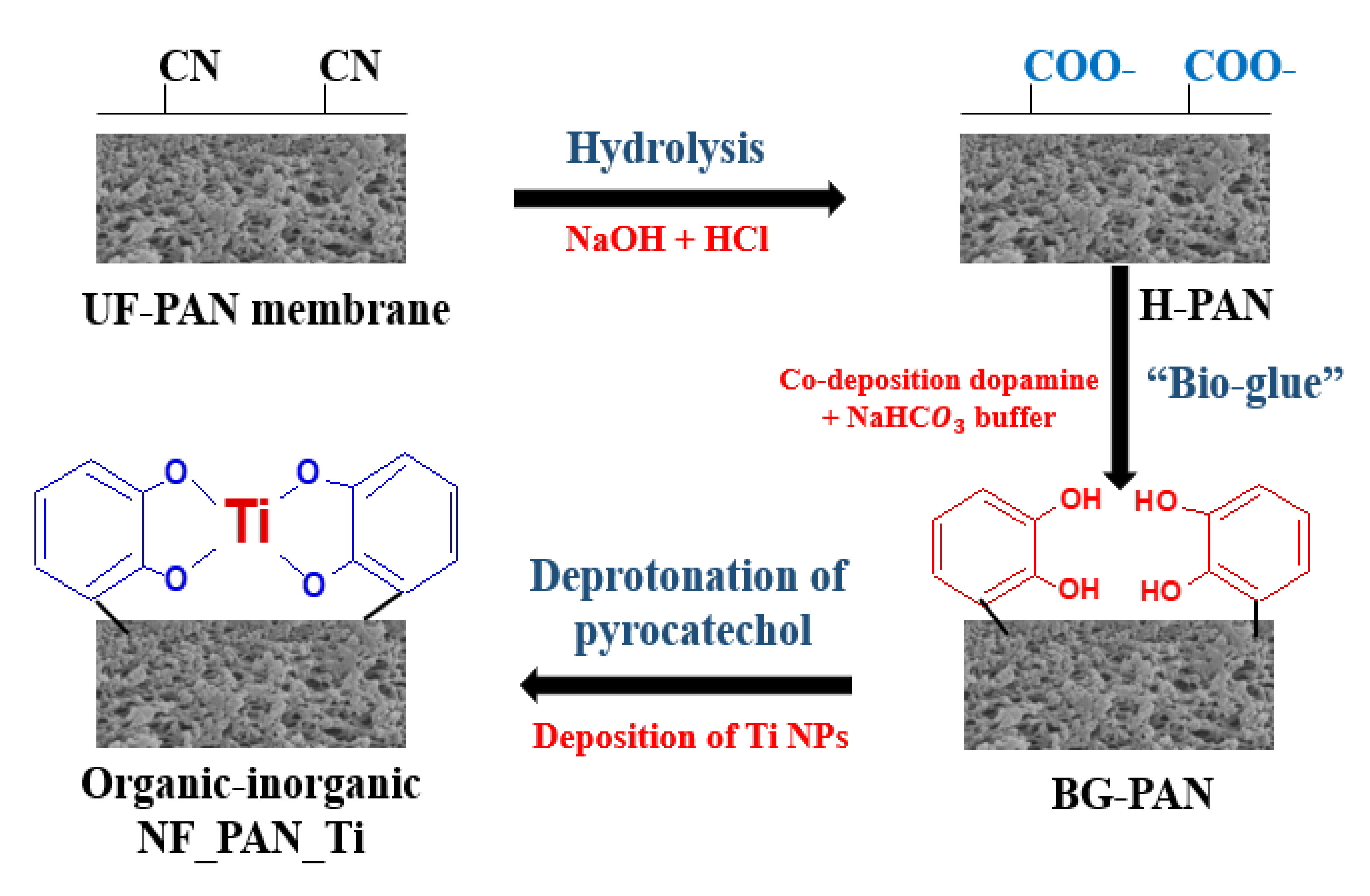
3.2. Novel Organic-Inorganic Nanofiltration Membrane NF_PAN_Ti Preparation

Step 1→PAN hydrolysis
PAN UF membrane was hydrolyzed in a sodium hydroxide (NaOH) solution (2 mol·L−1) for 2 h at 50 °C. The resulting membranes were transferred in a solution of hydrochloric acid (1.5 mol·L−1) for another two hours at 30 °C.
Step 2→“Bio-glue” solution preparation (S1) and deposition
A fresh solution (S1) was prepared by dissolving dopamine hydrochloride (DA) in sodium bicarbonate buffer (Buffer) solution (pH = 8.0; 50 mmol·L−1) for deposition. This preparation is based on the in situ formation approach of deposition of DA/Buffer on the membrane surface to generate a thin film layer coating PAN platform. The hydrolyzed PAN membrane was pre-wetted by ethanol for 30 min before its immersion into the solution (S1) and stirred at 30 °C for 2 h. The resulting membranes (DA-Buffer-coated hydrolyzed PAN membranes) were rinsed by deionized water before being dried in an oven.
Step 3→Nanoparticles Ti deposition
Titanium sulfate hydrate powder was dissolved in the solution of hydrochloric acid (50 mmol·L−1) at a concentration of 10 mmol·L−1 (S2). The DA/Buffer-coated hydrolyzed PAN membrane pieces were then immersed in the solution (S2), this time at air-room natural temperature for one day. Finally, the novel thin-film composite synthesized nanofiltration membrane, namely NF_PAN_Ti, was washed before being dried in an oven to later serve not only for characterization but also for further evaluation. Figure 3 shows the main steps for Ti NPs deposition.

3.3. NF_PAN_Ti Membrane Characterization

Field emission scanning electron microscopy (FESEM), Zeiss ZEISS Sigma500; Pittsburgh, PA, USA) was used to investigate the synthesized organic-inorganic membrane NF_PAN_Ti surface morphology and the results were reported and interpreted in this study.
An energy dispersive spectrometer (EDS) was combined in this study with field emission scanning electron microscopy for more insights on the membrane surface elements’ charge, their arrangement, and especially about the phase state of the titanium film. The elements observed on the membrane’s surface were titanium (Ti), carbon (C), nitrogen (N), and oxygen (O).
Atomic force microscopy, AFM (Multi-Mode VEECO- Denton, TX, USA, was very useful for nanofiltration NF_PAN_Ti morphology and roughness and the results were reported in this study and then interpreted.

3.4. Filtration Performance of Organic-Inorganic NF_PAN_Ti Membrane

The NF_PAN_Ti performance was performed due to a laboratory-scale cross-flow flat membrane module under 0.6 MPa at 30 °C. The effective surface of each sample was about 29.22 cm2. Various salts MgSO4, Na2·SO4, NaCl, CaCl2, and MgCl2 were dissolved in water with a concentration of 500 mg·L−1 and used as feed solutions with a fixed cross-flow rate of 30 L·h−1. The water flux (Fw, L·m−2·h−1) and rejection (R%) were calculated by the following equations, Equations (25) and (26):
F w = Q A · t      
where Q is the permeate-solution volume; A is the membrane effective surface, and t is the time of permeation through the membrane layer:
R = 1 C p C f × 100   %  
where Cp and Cf are respectively the solute particle concentration in the permeate-side and feed-side, and Cp and Cf were determined by Metrohm AG, Grüninger (Ionenstrasse 9100 Herisau, Switzerland) which is a conductivity meter and another instrument, ICP-OES-Optima 7300 DV, Perkin Elmer (Waltham, MA, USA).
The pore size of the novel organic-inorganic NF_PAN_Ti was estimated by the Guerout–Elford–Ferry equation (Equation (27)):
r p =   2.9 1.75 ε 8 η I Q ε A P 1 2
where ε is the overall-porosity, η is the water viscosity (8.9 × 10⁻⁴·Pa·s), Q is the permeate flux (m3/s), ∆P is the operating pressure 0.6 MPa, I is the membrane thickness (m), and A is the surface area of the membrane sample (m2).

3.5. Long Test Stability on NF_PAN_Ti Membrane

An immersion test was performed on the NF_PAN_Ti membrane for 6 days at room temperature without interruption. Both chemical removal and permeate flux were reported every 12 h.

3.6. Validation of the Predicted Results with Experimental Data

The relative error (RE) was calculated for each ion that passed through the membrane:
R E = R e x p e r i m e n t a l     R m o d e l R e x p e r i m e n t a l  

4. Results and Discussion

4.1. NF_PAN_Ti Structures Characterization

Figure 4a,b show the surface roughness and morphology of the novel synthesized organic-inorganic thin-film composite NFMs, the characteristics of which are valuable in nanofiltration. The hydrolyzed UF membrane, once modified by deposition of titanium nanoparticles, displays a really smooth surface with invisible pores (Figure 4b), while the membrane roughness is very small in accordance with the AFM image depicted in Figure 4a. The membrane roughness decreases dramatically to reach Ra   =   7.17   nm for the NF_PAN_Ti membrane. The DA / Buffer coating the PAN platform, which acts like “bio-glue”, played an important role in this deposition of Ti nanoparticles on the substrate, UF PAN membrane. Y. Lv et al. recently concluded in their investigation carried out on a thin-film composite nanofiltration membrane that the smooth and dense selective active layer is of great importance for high rejection performance [6]. NF_PAN_Ti membrane may therefore provide an excellent solute particle removal and high permeation performance. This assertion will be verified later in this investigation.
To provide more insights into the arrangement or potential function of the Ti nanoparticles (NPs) layer that took form on the PAN substrate, the energy dispersive spectrometer (EDS) was used as reinforcement of the field emission scanning electron microscopy (FESEM). In Figure 5e, the results of the energy spectrum analysis of the NF_PAN_Ti membrane are reported. The EDS reported four different elements carbon (C), oxygen (O), nitrogen   (N), and titanium (Ti) due to their unique X-ray signals. The elements Ti , C , O , and N   are not distributed unevenly on the surface of the NF_PAN_Ti membrane as depicted in Figure 5b–e, respectively. Thus, it is possible to characterize and modify the materials at the atomic scale, providing unparalleled insight into the behavior of nanomaterials and particles, since each atomic position can be clearly distinguished by its unambiguous chemical signal (Figure 5a). The UF membrane used as a substrate is a polymeric membrane, so carbon is the most dominant element of the novel membrane and a very strong signal is observed at its position. The individual atomic columns are visible and distinct from the neighbors owing to their high contrast.

4.2. Flux Behavior and Experimental Salts Rejection

Figure 6a shows the water flux of NF_PAN_Ti membrane for different salt solutions obtained from MgSO 4 ,   Na 2 SO 4 ,   NaCl ,   CaCl 2 ,   and   MgCl 2 at various applied transmembrane pressures of 0.2, 0.3, 0.4, 0.5, and 0.6 MPa. For all salts, plots of water flux F w vs. Δ P e depicted perfect similarity for all solutions over the whole range of pressures investigated (0.2–0.6 MPa). The data lies on an almost similar plot to a very good approximation. This leads to an experimental confirmation that electrokinetic effects do not have great influence. For the NF_PAN_Ti membrane, the salts’ rejection increased slightly with the increase of pressure and stabilized around Δ P e = 0.6   MPa . This justifies the choice in the present study of optimum pressure at 0.6 MPa.
In Figure 6a,b, the organic-inorganic NF membrane NF_PAN_Ti showed an excellent rejection performance towards MgSO4 and MgCl2 CaCl2 salts respectively up to 93.8%, 89.3%, and 99.2%. The rejection of both Na2SO4 and NaCl salts was very poor (respectively 24.1% and 28.3%). As a result, NF_PAN_Ti has been shown to be able to effectively reject multivalent ions from water and was incompetent at removing monovalent anions. This point of view is widely shared by a large number of scientists who have made recent investigations [7,31]. Table 2 provides an overview of the useful data used in the model.

4.3. Model Reassessment of Salts Rejection

Figure 7 depicts the solute particle concentration in the novel organic-inorganic NF_PAN_Ti active layer as a function of the step size for various solution flux Qv, Figure 7a for Mg2+ and Figure 7b for Cl.
Globally, it was noticed that both Cl and Mg2+ ions’ removal increased as the water-flux (Qv) through the NF membrane increased. Since the thickness of the membrane ∆x was divided by 100 in order to have a good result, the xstep was set at 11.8 nm = 1.18 × 10 nm. NF_PAN_Ti rejection of Mg2+ was more remarkable than Cl removal. Such rejection behavior is partly due to the intrinsic membrane charge, which in the typical case of NF_PAN_Ti is of a positive charge. Figure 3 shows the deposition of Ti4+ ion on the membrane surface.
From Equations (4) and (6), the NF_PAN_Ti charge effect appeared in the module in the electrical potential gradient and resulted in a disparate influence on Cl and Mg2+ removal. Repulsion between the NF_PAN_Ti membrane and Mg2+ ions occurred, since they are both positively charged; at the same time, the attraction between the NF_PAN_Ti membrane and Cl ions took place (this attraction is facilitated by the fact that they are of opposite signs). In other words, the Cl ions could pass more easily across the NF_PAN_Ti active layer while the Mg2+ ions could find themselves prevented from crossing through. For both plots shown in Figure 6a,b, the concentration of the solute particles Cl and Mg2+ in the target layer of NF_PAN_Ti decreased as the particles moved from one side (feed) to another (permeate) (Table 3).
Another parameter that affected Cl and Mg2+ solute particles’ removal is the pore size rp of the NF_PAN_Ti active layer related to both hindrance coefficients already explained in the mathematical modeling equations, namely Ki,c for convection and Ki,d for diffusion, as it was clarified in Equations (8), (12), and (13)
In the specific case of water flux Qv of 58 L·m−2·h−1, the concentrations of Cl and Mg2+ ions across the NF_PAN_Ti membrane can be determined by the respective equations, Ci,p(Cl) = −0.5353·xsteDA + 2.6316 and Ci(Mg2+) = −3.9785·xstep + 5.2631. For xstep = 1.18, we are in the permeate, so Ci,p(Cl) = 1.9999 mol/m3 and Ci,p(Mg2+) = 0.5684.

4.4. Membrane Long-Term Stability

In order to evaluate the long-term stability of the NF_PAN_Ti membrane, a continuous filtration test of 144 h was performed. The results are shown in Figure 8. Among all the salts used in this study, MgCl2 was selected to verify the long-term stability of the membrane.
For test conditions, the concentration of MgCl [500 mg/L], temperature = 30 °C, pH = 6.0, transmembrane pressure of 0.6 MPa, and cross-flow rate = 30 L·h−1 were used. Globally, the novel organic-inorganic TFC NFMs NF_PAN_Ti showed satisfying long-term stability for both the permeate flux and salts removal. The water flux of the NF_PAN_Ti membrane remains quite constant over time for a decrease of less than 1%. The water flux, during the long-term operation, changed very slightly and remained high (about 58 L·m−2·h−1) till the end of the test. During the 6-day test, the synthesized NF membrane exhibited an excellent rejection of close to 89% towards MgCl2. The good durability of NF_PAN_Ti membrane is interrelated with the interfacial harmony between the TiO2 nanoparticles (NPs) as a selective layer and the support surface UF polyacrylonitrile (PAN) membrane through the robust and multiple binding forces between DA/Buffer (bio-glue) coating hydrolyzed PAN. This 144-day test made it possible to appreciate the long-term effectiveness of the novel organic-inorganic thin film composite nanofiltration membrane prepared in this work.
The synthesized organic-inorganic membrane (NF_PAN_Ti) water flux and rejection performance is reported in Table 4 below with those of some earlier reported ones.
NF_PAN_Ti membrane, although very loose, is effective at removing multivalent ions. The permeate flux and the rejection are the two main parameters that help to decide whether an NF membrane is efficient or not [35]. Most often, if NF membrane exhibits high permeate flux, it is less selective, and conversely, if it displays excellent rejection, it has a low permeate flux release.
Recently, G. R. Xu et al. reported a high flux NF membrane based on layer-by-layer assembly-modified electrospun nanofibrous substrate, where the experiments results indicated that the resulting membranes exhibited a high permeate flux of about 75 L·m−2·h−1 with the MgSO4 rejection close to 80%.

4.5. Validation of the Predicted Results with Experimental Data

This small error was predictable because we took a very small xstep (membrane thickness was divided by 100) (Table 5). It should also be noted that it was more difficult to provide the experimental results with several significant true digits. What is important and striking is the precision with which the model provides the results if the input data are correctly defined under optimal experimental conditions.

5. Conclusions

The tools in vogue, especially field emission scanning electron microscopy (FESEM), energy dispersive spectroscopy (EDS), and atomic force microscopy (AFM), have made it possible to fully characterize the structure of the novel organic-inorganic nanofiltration (NF) membrane, namely NF_PAN_Ti. A soft computing model was applied to make the rebarbative extended Nernst–Planck equations commonplace, which govern the transport of ions through NF membranes. Euler’s numerical method, a simple and direct computing method, was therefore applied with a small step size, and the results obtained were very interesting. The novel membrane was very loose and exhibited excellent rejection towards multivalent ions and the salts rejection sequence Na2SO4 < NaCl < MgCl2 < MgSO4 < CaCl2. Euler’s numerical method corroborated the experimental findings perfectly since the relative error was found very low at 0.33% for Cl and 0.09% for Mg2+ Re<<0.1
We strongly recommend that the scientific world study the distinctive characteristics of the next-generation NF membranes by incorporating the use of simple but effective models for more reliable results. In addition to the use of prediction models, the role of the isoelectric point (pH of zero-charge) of nanoparticles generating electrical forces between ions and NPs may also be the subject of further investigation.

Author Contributions

Conceptualization, C.N.W.; methodology, C.N.W.; software, C.N.W. and A.D.; validation, Z.C.; formal analysis, C.N.W., J.K., J.S., P.Y., W.W. and Y.G.; investigation, Y.G. and C.N.W.; resources, Z.C.; data curation, J.K., J.S., P.Y., W.W. and Y.G.; writing—original draft preparation, C.N.W. and A.D.; writing—review and editing, J.K. and J.S.; visualization, A.D.; supervision, Z.C.; project administration, Z.C.; funding acquisition, Z.C. All authors have read and agreed to the published version of the manuscript.

Funding

The work was supported by the National Key R&D Program of China (Grant No. 2019YFD1100104).

Data Availability Statement

No new data were created or analyzed in this study. Data sharing is not applicable to this article.

Acknowledgments

The authors would like to thank our research group members for their kind help and suggestions.

Conflicts of Interest

The authors declare no conflict of interest.

Abbreviations

c i concentration of ion i within pore, mol·m−3
C f bulk feed concentration, mol·m−3
C i ionic solute bulk solution concentration, mol·m−3
C p uncharged solute bulk permeate concentration, mol·m−3
D p / D i ,   p (Un)charged solute pore diffusion coefficient, m2·s−1 (= K d D )
D solute bulk diffusion coefficient, m2·s−1
Iionic strength (mol·m−3)
j s uncharged solute flux, pore area basis, mol·m−2·s−1
kfeed-side mass transfer coefficient, m/s
PPressure N/m2
r p effective pore radius, m
Vsolvent velocity, m/s
X d effective charge density, mol/m3
z i valence of ion i
γ i activity coefficient of ion i within pore, dimensionless
γ i 0 bulk activity coefficient of ion i, dimensionless
Δ P applied pressure, N·m−2
Δ P e effective pressure driving force, N·m−2
Δ x membrane thickness, m
Δ Π osmotic pressure difference, N·m−2
Δ ψ D Donnan potential, V
Ɛ b Ɛ p Bulk/pore dielectric constant, dimensionless
ηsolvent viscosity within pores, N·s·m−2
λratio of ionic or uncharged solute radius to pore radius, dimensionless
ξ ratio of effective membrane charge density to bulk feed concentration, di-mensionless ( ξ = X d / C f )
Φ i steric partition coefficient of ion i, dimensionless
𝜓potential within the pore (V)

References

  1. Wang, Y.; Zucker, I.; Boo, C.; Elimelech, M. Removal of Emerging Wastewater Organic Contaminants by Polyelectrolyte Multilayer Nanofiltration Membranes with Tailored Selectivity. ACS ES&T Eng. 2020. [Google Scholar] [CrossRef]
  2. Elimelech, M.; Phillip, W.A. The future of seawater desalination: Energy, technology, and the environment. Science 2011, 333, 712–717. [Google Scholar] [CrossRef] [PubMed]
  3. Chua, Y.T.; Lin, C.X.C.; Kleitz, F.; Zhao, X.S.; Smart, S. Nanoporous organosilica membrane for water desalination. Chem. Commun. 2013, 49, 4534. [Google Scholar] [CrossRef] [PubMed]
  4. Oatley-Radcliffe, D.L.; Walters, M.; Ainscough, T.J.; Williams, P.M.; Mohammad, A.W.; Hilal, N. Nanofiltration membranes and processes: A review of research trends over the past decade. J. Water Process. Eng. 2017, 19, 164–171. [Google Scholar] [CrossRef] [Green Version]
  5. Elcik, H.; Celik, S.O.; Cakmakci, M.; Ozkaya, B. Performance of nanofiltration and reverse osmosis membranes for arsenic removal from drinking water. Desalinisation Water Treat. 2015, 57, 20422–20429. [Google Scholar] [CrossRef]
  6. Lv, Y.; Yang, H.-C.; Liang, H.-Q.; Wan, L.; Xu, Z.-K. Novel nanofiltration membrane with ultrathin zirconia film as selective layer. J. Membr. Sci. 2016, 500, 265–271. [Google Scholar] [CrossRef]
  7. Nicomel, N.R.; Leus, K.; Folens, K.; Van Der Voort, P.; Du Laing, G. Technologies for Arsenic Removal from Water: Current Status and Future Perspectives. Int. J. Environ. Res. Public Heal. 2015, 13, 62. [Google Scholar] [CrossRef]
  8. Hafiz, M.; Hawari, A.H.; Alfahel, R.; Hassan, M.K.; Altaee, A. Comparison of Nanofiltration with Reverse Osmosis in Reclaiming Tertiary Treated Municipal Wastewater for Irrigation Purposes. Membranes 2021, 11, 32. [Google Scholar] [CrossRef]
  9. Ruiz-García, A.; Dimitriou, E.; Nuez, I. Retrofitting assessment of a full-scale brackish water reverse osmosis desalination plant with a feed capacity of 600 m3/d. Desalinisation Water Treat. 2019, 144, 72–78. [Google Scholar] [CrossRef]
  10. Higgins, C.J.; Duranceau, S.J. Removal of Enantiomeric Ibuprofen in a Nanofiltration Membrane Process. Membranes 2020, 10, 383. [Google Scholar] [CrossRef]
  11. Zakmout, A.; Sadi, F.; Portugal, C.A.M.; Crespo, J.G.; Velizarov, S. Tannery Effluent Treatment by Nanofiltration, Reverse Osmosis and Chitosan Modified Membranes. Membranes 2020, 10, 378. [Google Scholar] [CrossRef]
  12. Cai, Y.-H.; Yang, X.J.; Schäfer, A.I. Removal of Naturally Occurring Strontium by Nanofiltration/Reverse Osmosis from Groundwater. Membranes 2020, 10, 321. [Google Scholar] [CrossRef]
  13. Marszałek, A.; Puszczało, E. Effect of Photooxidation on Nanofiltration Membrane Fouling During Wastewater Treatment from the Confectionery Industry. Water 2020, 12, 793. [Google Scholar] [CrossRef] [Green Version]
  14. Marecka-Migacz, A.; Mitkowski, P.T.; Antczak, J.; Różański, J.; Prochaska, K. Assessment of the Total Volume Membrane Charge Density through Mathematical Modeling for Separation of Succinic Acid Aqueous Solutions on Ceramic Nanofiltration Membrane. Processes 2019, 7, 559. [Google Scholar] [CrossRef] [Green Version]
  15. Ali, A.; Nymann, M.C.; Christensen, M.L.; Quist-Jensen, C.A. Industrial Wastewater Treatment by Nanofiltration—A Case Study on the Anodizing Industry. Membranes 2020, 10, 85. [Google Scholar] [CrossRef]
  16. Cooray, T.; Wei, Y.; Zhang, J.; Zheng, L.; Zhong, H.; Weragoda, S.; Weerasooriya, R. Drinking-Water Supply for CKDu Affected Areas of Sri Lanka, Using Nanofiltration Membrane Technology: From Laboratory to Practice. Water 2019, 11, 2512. [Google Scholar] [CrossRef] [Green Version]
  17. Shao, W.; Liu, C.; Yu, T.; Xiong, Y.; Hong, Z.; Xie, Q. Constructing Positively Charged Thin-Film Nanocomposite Nanofiltration Membranes with Enhanced Performance. Polymers 2020, 12, 2526. [Google Scholar] [CrossRef]
  18. Thi, H.Y.N.; Nguyen, B.T.D.; Kim, J.F. Sustainable Fabrication of Organic Solvent Nanofiltration Membranes. Membranes 2020, 11, 19. [Google Scholar] [CrossRef]
  19. Lesimple, A.; Ahmed, F.E.; Hilal, N. Remineralization of desalinated water: Methods and environmental impact. Desalination 2020, 496, 114692. [Google Scholar] [CrossRef]
  20. Mohammad, A.W.; Teow, Y.; Ang, W.; Chung, Y.T.; Oatleyradcliffe, D.L.; Hilal, N. Nanofiltration membranes review: Recent advances and future prospects. Desalination 2015, 356, 226–254. [Google Scholar] [CrossRef]
  21. Van der Bruggen, B. Chemical modification of polyethersulfone nanofiltration membranes: A review. J. Appl. Polym. Sci. 2009, 114, 630–642. [Google Scholar] [CrossRef]
  22. Seah, M.Q.; Lau, W.J.; Goh, P.S.; Tseng, H.-H.; Wahab, R.A.; Ismail, A.F. Progress of Interfacial Polymerization Techniques for Polyamide Thin Film (Nano)Composite Membrane Fabrication: A Comprehensive Review. Polymers 2020, 12, 2817. [Google Scholar] [CrossRef]
  23. Han, Y.; Xu, Z.; Gao, C. Ultrathin Graphene Nanofiltration Membrane for Water Purification. Adv. Funct. Mater. 2013, 23, 3693–3700. [Google Scholar] [CrossRef]
  24. Greenlee, L.F.; Lawler, D.F.; Freeman, B.D.; Marrot, B.; Moulin, P. Reverse osmosis desalination: Water sources, technology, and today’s challenges. Water Res. 2009, 43, 2317–2348. [Google Scholar] [CrossRef]
  25. Lee, A.; Elam, J.W.; Darling, S.B. Membrane materials for water purification: Design, development, and application. Environ. Sci. Water Res. Technol. 2016, 2, 17–42. [Google Scholar] [CrossRef]
  26. Gryta, M. Fouling in direct contact membrane distillation process. J. Memb. Sci. 2008, 325, 383–394. [Google Scholar] [CrossRef]
  27. Boffa, V. Fabrication of ultramicroporous silica membranes for pervaporation and gas separation. In Molecules at Work: Selfassembly, Nanomaterials, Molecular Machinery; Wiley & Sons: Hoboken, NJ, USA, 2012; pp. 177–205. [Google Scholar]
  28. Xu, R.; Wang, J.; Kanezashi, M.; Yoshioka, T.; Tsuru, T. Reverse osmosis performance of organosilica membranes and comparison with the pervaporation and gas permeation properties. AIChE J. 2012, 59, 1298–1307. [Google Scholar] [CrossRef]
  29. Xu, R.; Wang, J.; Kanezashi, M.; Yoshioka, T.; Tsuru, T. Development of Robust Organosilica Membranes for Reverse Osmosis. Langmuir 2011, 27, 13996–13999. [Google Scholar] [CrossRef] [PubMed]
  30. Van Gestel, T. Corrosion properties of alumina and titania NF membranes. J. Membr. Sci. 2003, 214, 21–29. [Google Scholar] [CrossRef]
  31. Song, Z.; Fathizadeh, M.; Huang, Y.; Chu, K.H.; Yoon, Y.; Wang, L.; Xu, W.L.; Yu, M. TiO2 nanofiltration membranes prepared by molecular layer deposition for water purification. J. Membr. Sci. 2016, 510, 72–78. [Google Scholar] [CrossRef] [Green Version]
  32. Xu, Q.; Anderson, M.A. ChemInform Abstract: Sol-Gel Route to Synthesis of Microporous Ceramic Membranes: Preparation and Characterization of Microporous TiO2 and ZrO2 Xerogels. ChemInform 2010, 25, 1939–1945. [Google Scholar] [CrossRef]
  33. Sekulić, J.; Elshof, J.E.T.; Blank, D.H.A. A Microporous Titania Membrane for Nanofiltration and Pervaporation. Adv. Mater. 2004, 16, 1546–1550. [Google Scholar] [CrossRef]
  34. Marchetti, P.; Solomon, M.F.J.; Szekely, G.; Livingston, A.G. Molecular Separation with Organic Solvent Nanofiltration: A Critical Review. Chem. Rev. 2014, 114, 10735–10806. [Google Scholar] [CrossRef] [PubMed]
  35. Siddique, T.; Dutta, N.K.; Choudhury, N.R. Nanofiltration for Arsenic Removal: Challenges, Recent Developments, and Perspectives. Nanomaterials 2020, 10, 1323. [Google Scholar] [CrossRef]
  36. Van der Bruggen, B.; Vandecasteele, C. Removal of pollutants from surface water and groundwater by nanofiltration: Overview of possible applications in the drinking water industry. Environ. Pollut. 2003, 122, 435–445. [Google Scholar] [CrossRef]
  37. Bandini, S.; Vezzani, D. Nanofiltration modeling: The role of dielectric exclusion in membrane characterization. Chem. Eng. Sci. 2003, 58, 3303–3326. [Google Scholar] [CrossRef]
  38. Bowen, W.R.; Mukhtar, H. Characterisation and prediction of separation performance of nanofiltration membranes. J. Membr. Sci. 1996, 112, 263–274. [Google Scholar] [CrossRef]
  39. Wong, W.; Wong, H.Y.; Badruzzaman, A.B.M.; Goh, H.H.; Uz-Zaman, A.M.M. Recent advances in exploitation of nanomaterial for arsenic removal from water: A review. Nanotechnology 2016, 28, 042001. [Google Scholar] [CrossRef]
  40. Bowen, W.R.; Mohammad, A.W. Diafiltration by nanofiltration: Prediction and optimization. AIChE J. 1998, 44, 1799–1812. [Google Scholar] [CrossRef]
  41. Sigurdardottir, S.B.; DuChanois, R.M.; Epsztein, R.; Pinelo, M.; Elimelech, M. Energy barriers to anion transport in nanofiltration membranes: Role of intra-pore diffusion. J. Membr. Sci. 2020, 603, 117921. [Google Scholar] [CrossRef]
  42. Nguyen, D.T.; Nguyen, S.; Hoang, T.A.; Yin, G. Tamed-Euler method for hybrid stochastic differential equations with Markovian switching. Nonlinear Anal. Hybrid. Syst. 2018, 30, 14–30. [Google Scholar] [CrossRef]
  43. Zhang, W. Convergence of the balanced Euler method for a class of stochastic Volterra integro-differential equations with non-globally Lipschitz continuous coefficients. Appl. Numer. Math. 2020, 154, 17–35. [Google Scholar] [CrossRef]
  44. Gojković, L.; Malijević, S.; Armaković, S. Modeling of fundamental electronic circuits by the Euler method using the Python programming language. Phys. Educ. 2020, 55, 055016. [Google Scholar] [CrossRef]
  45. Yue, C.; Zhao, L. Strong convergence of the split-step backward Euler method for stochastic delay differential equations with a nonlinear diffusion coefficient. J. Comput. Appl. Math. 2021, 382, 113087. [Google Scholar] [CrossRef]
  46. Benner, P.; Stillfjord, T.; Trautwein, C. A linear implicit Euler method for the finite element discretization of a controlled stochastic heat equation. 2020. Available online: https://arxiv.org/abs/2006.05370 (accessed on 23 December 2020).
  47. Bowen, W.R.; Welfoot, J.S. Modelling the performance of membrane nanofiltration—critical assessment and model development. Chem. Eng. Sci. 2002, 57, 1121–1137. [Google Scholar] [CrossRef]
  48. Van Gestel, T.; Vandecasteele, C.; Buekenhoudt, A.; Dotremont, C.; Luyten, J.; Leysen, R.; Van Der Bruggen, B.; Maes, G. Salt retention in nanofiltration with multilayer ceramic TiO2 membranes. J. Membr. Sci. 2002, 209, 379–389. [Google Scholar] [CrossRef]
  49. Gholami, S.; López, J.; Rezvani, A.; Cortina, J.L.; Cortina, J.L. Fabrication of thin-film nanocomposite nanofiltration membranes incorporated with aromatic amine-functionalized multiwalled carbon nanotubes. Rejection performance of inorganic pollutants from groundwater with improved acid and chlorine resistance. Chem. Eng. J. 2020, 384, 123348. [Google Scholar] [CrossRef]
  50. Ghazali, N.F.; Lim, K.M. Mass Transport Models in Organic Solvent Nanofiltration: A Review. J. Adv. Resear. Fluid 2020, 76, 126–138. [Google Scholar] [CrossRef]
  51. Zilberbrand, M. A nonelectrical mechanism of ion exclusion in thin water films in finely dispersed media. J. Colloid Interface Sci. 1997, 192, 471–474. [Google Scholar] [CrossRef]
  52. Xu, G.-R.; Liu, X.-Y.; Xu, J.-M.; Li, L.; Su, H.-C.; Zhao, H.-L.; Feng, H.-J. High flux nanofiltration membranes based on layer-by-layer assembly modified electrospun nanofibrous substrate. Appl. Surf. Sci. 2018, 434, 573–581. [Google Scholar] [CrossRef]
  53. Bagheripour, E.; Moghadassi, A.; Hosseini, S.; Ray, M.; Parvizian, F.; Van Der Bruggen, B. Highly hydrophilic and antifouling nanofiltration membrane incorporated with water-dispersible composite activated carbon/chitosan nanoparticles. Chem. Eng. Res. Des. 2018, 132, 812–821. [Google Scholar] [CrossRef]
  54. Vatanpour, V.; Madaeni, S.S.; Moradian, R.; Zinadini, S.; Astinchap, B. Novel antibifouling nanofiltration polyethersulfone membrane fabricated from embedding TiO2 coated multiwalled carbon nanotubes. Sep. Purif. Technol. 2012, 90, 69–82. [Google Scholar] [CrossRef]
  55. Vatanpour, V.; Esmaeili, M.; Farahani, M.H.D.A. Fouling reduction and retention increment of polyethersulfone nanofiltration membranes embedded by amine-functionalized multi-walled carbon nanotubes. J. Membr. Sci. 2014, 466, 70–81. [Google Scholar] [CrossRef]
  56. Zinadini, S.; Zinatizadeh, A.A.; Rahimi, M.; Vatanpour, V.; Zangeneh, H. Preparation of a novel antifouling mixed matrix PES membrane by embedding graphene oxide nanoplates. J. Membr. Sci. 2014, 453, 292–301. [Google Scholar] [CrossRef]
  57. Zhang, H.; Li, B.; Pan, J.; Qi, Y.; Shen, J.; Gao, C.; Van Der Bruggen, B. Carboxyl-functionalized graphene oxide polyamide nanofiltration membrane for desalination of dye solutions containing monovalent salt. J. Membr. Sci. 2017, 539, 128–137. [Google Scholar] [CrossRef]
  58. Miao, J.; Zhang, L.-C.; Lin, H. A novel kind of thin film composite nanofiltration membrane with sulfated chitosan as the active layer material. Chem. Eng. Sci. 2013, 87, 152–159. [Google Scholar] [CrossRef]
Figure 1. Flowchart describing the computation procedure.
Coatings 11 00184 g001
Figure 2. Ion transport across the organic-inorganic NF_PAN_Ti membrane.
Coatings 11 00184 g002
Figure 3. Steps of novel organic-inorganic nanofiltration membrane NF_PAN_Ti preparation.
Coatings 11 00184 g003
Figure 4. Novel organic-inorganic NF_PAN_Ti membrane (a) atomic force microscopy (AFM) image, (b) FESEM (field emission scanning electron microscopy), and (c) energy spectra of Ti element.
Coatings 11 00184 g004
Figure 5. (a) Energy spectrum analysis results of the NF_PAN_Ti and the sample table surface elements containing (b) carbon, (c) oxygen, (d) nitrogen, and (e) titanium.
Coatings 11 00184 g005
Figure 6. (a) Permeate flux and salts removal of NF_PAN_Ti as a function of transmembrane pressure and (b) water flux and salts rejection of NF_PAN_Ti under optimal conditions, Pressure   =   0.6   MPa , Temperature   =   25   ° C , [ Salts ]   =   500 mg · L 1 , pH   =   10 ± 0.5 .
Coatings 11 00184 g006
Figure 7. (a) Mg 2 +   ion concentration in the organic-inorganic NF_PAN_Ti active layer as a function of the step size (for various solutions flux (Qv)); (b) Cl   ion concentration in the organic-inorganic NF_PAN_Ti active layer as a function of the step size (for various solutions flux (Qv)).
Coatings 11 00184 g007aCoatings 11 00184 g007b
Figure 8. Long-term stability test on the novel fabricated membrane (NF_PAN_Ti). Test conditions: 0.6   MPa ; cross flow   rate   =   30   L · h 1 ; [ MgCl 2 ]   =   500   mg / L , 144-h test.
Coatings 11 00184 g008
Table 1. Basic parameters used in the model computation run.
ParametersValue
Faraday’s constant (F)96,487 C·mol−1
Permittivity   of   free   space   ( Ɛ 0 ) 8.85419 × 10 12   J 1 · C 2 · m 1
Operating temperature (T)303.15 K
pH in the oxidant unit10.2
Operating   pressure   ( Δ P e )0.60 MPa
Crossflow velocity 30   L · h 1
Boltzmann constant (k)1.38066 × 10⁻²³ J·K−1
Table 2. Membrane parameters used in this work.
ParameterUnitValueRefs
NaCl   rejection % 24.1 This study
MgCl 2 rejection % 89.3
Water flux L · m 2 · h 1 58
Membrane geometry Flat sheet 1   m × 1   m
Membrane surface area cm 2 29.22
Membrane thickness nm 1180 ± 7.17
r p nm 0.538 Equation (27)
Table 3. Stokes radii, partial molar volumes, and diffusivities of solute particles.
Particle D
10 9   m 2 · s 1
a s = r i
nm
V s   o r   V i
c m 3 · mo l 1
References
C l 2.030.12117.82[49,50,51]
M g 2 + 0.720.348−21.57
Table 4. Synthesized membrane water flux and rejection performance in this study and some earlier reported ones.
MembranesWater Flux
(L·m−2·h−1)
Rejection (%)References
NF _ PAN _ Ti 5889.3This study
PES / LbL   Nanofibrous 7580[52]
HPAN /   ZrO 2 60>90[6]
Modified   membranes   0.5 Ach 3095[53]
PES TiO 2 4.281.9[54]
PES / functionalized   MWCNTs 2480[55]
PES Graphene   Oxide GO 20.496[56]
Graphene   oxide   polyamide 4290[57]
TFC NF / functionalized   chitosan 22.990.8[58]
Table 5. Experimental and predicted rejections followed by error estimate.
NF_PAN_Ti membrane
Experimental Predicted Error   %
Cl 24.124.01910.33
Mg 2 + 89.389.21520.09
Publisher’s Note: MDPI stays neutral with regard to jurisdictional claims in published maps and institutional affiliations.

