Article

The Influence of the Powder Characteristics on 316L Stainless Steel Coatings Sprayed by Cold Gas Spray

Thermal Spray Center CPT, University of Barcelona, Martí i Franqués 1, 7a Planta, 08028 Barcelona, Spain
*
Author to whom correspondence should be addressed.
Coatings 2021, 11(2), 168; https://doi.org/10.3390/coatings11020168
Submission received: 11 December 2020 / Revised: 22 January 2021 / Accepted: 27 January 2021 / Published: 31 January 2021
(This article belongs to the Section Surface Characterization, Deposition and Modification)

Abstract

:
Thermally sprayed 316L stainless steel coatings are commonly used on metallic structures due to their corrosion and wear resistance when compared to carbon steel. Cold Gas Spray (CGS) is a convenient thermal spray process to deposit 316L coatings, producing thick and very dense coatings, with almost no deleterious changes on the feedstock properties to the coating condition. The powder characteristics have influence on the microstructure of the coating, such as porosity and oxide contents, which alter its corrosion and wear behavior. CGS is an efficient technique to reduce the problems associated with material melting commonly found in other conventional thermal spray methods. In this work, different 316L powders, produced by different manufacturers, were deposited by CGS, applying the same equipment and parameters, with the objective to evaluate the relation between the powders’ characteristics and coating properties. Their microstructure, adherence, hardness, as well as the performance on corrosion and wear testing were evaluated. The water atomized powders presented in general better results than gas atomized powders.

1. Introduction

Metallic components and/or metallic structures are exposed to different conditions during their lifetime. The operational and environmental conditions must be considered during their design, fabrication, maintenance and inspection steps, since wear or corrosion could occur in working conditions. For this reasons, the application of coatings on the new components have been widely used, employing different techniques, such painting, galvanizing, Physical Vapor Deposition (PVD), Chemical Vapor Deposition (CVD), welding, thermal spraying, and other processes [1,2,3,4]. The selection of the protection methodology and coating materials depends on its purpose, such corrosion, wear, or cavitation resistance, or aesthetic purpose. Among thermal spray processes, CGS is a deposition technique used to fabricate coatings or to repair worn areas of free standing parts [5,6,7]. Nowadays, CGS is accepted as a spray technique capable of depositing thick metal layers on different substrates at relatively low processing temperatures, maintaining the initial phase composition of different feedstock powders. Since the starting powders used in CGS remain in the solid state during the deposition, the most common defects of the high-temperature thermal spray processes, such phase transformation or oxidation, can be avoided [8,9,10,11].
The 316L stainless steel offers high creep resistance, desirable machinability, and significant tensile strength at high temperatures, as well as wear and corrosion resistance, which accredit it to applications in aerospace, automotive, medical implants, pharmaceuticals and biomedical industries, food preparation equipment, oil and gas sectors, marine, and architectural applications [12]. It is also used to coat carbon steel or to repair 316L damaged parts.
The feedstock powder for CGS can be manufactured by different techniques, resulting in different powders characteristics and properties [13,14]. For example, the gas atomization process produces spherical powders, while the water atomization confers to the powders an irregular shape, and it is typically a cheaper process than gas atomization [15,16]. About the selection of an specific shape powders to be used in CGS, for Jeandin et al. [17], it depends on the answering of two main questions: first, how the particles impinge during the process and second, the nature of the bonding between two adjacent splats. It is clear that both answers depend on the powder shape, which influences the particle deformation at the impact and adhesion mechanisms. The resistance on tensile testing and the hardness of Ag irregular powder CGS sprayed coatings were higher than the Ag spherical shape, even after heat treatment [17]. Some mechanisms collaborate to the adhesion of the particles to the substrate as listed by Sun et al. [18]: the adiabatic shear instability (ASI), caused by the high velocity of the powder particle, breaks the natural oxide film on the surface of both the particle and the substrate and the progressive plastic flow of the materials enables metallic bonding at atomic scale through direct contact between the adjacent fresh metal surfaces; mechanical interlocking, interfacial mixing, local melting and diffusion [19,20,21,22,23].
Particles velocity is among the most important parameters of CGS, which works well in a window of operation, meaning that the particles must impact to the substrate above a critical velocity and under a maximum velocity. It occurs due to the fact that slow particles does not attach or anchor to the substrate and particles with an excessive velocity erode the substrate [9]. It is well known that the higher the velocity of the particles, the lower the porosity, the higher the adhesion strength and the higher the corrosion resistance and hardness of the cold sprayed coating [10,12,24]. Fukanuma et al. [25] investigated experimentally how particle morphology affects particle acceleration in a CGS supersonic gas flow. They sprayed 316L powders with spherical and irregular morphologies, resulting the irregular 316L particles is faster than the spherical ones at the same process conditions. According to these authors, this is due to the higher drag coefficient of the angular particle. Jodoin et al. [26], using the CGS process, measured the higher velocity for particles of Al alloys cryomilled (irregular) than the atomized ones. Schmidt, Gaertner, and Kreye [24] also presented the influence of the particle size on the velocity of particles, since the bigger the particles the lower the velocity and the temperature reached, mainly due their mass and inertia to the movement. Evaluating the size of 316L particles, Adachi and Ueda [27] presents the smallest particles (–20 + 5 µm) producing denser CGS coatings than bigger particles (–45 + 10 µm and –53 + 20 µm).
This work aims to evaluate the effect of the 316L feedstock powders characteristics on the CGS coatings properties, microstructures, corrosion, and wear performance. To accomplish this objective, fully dense 316L coatings were prepared via CGS, using four different 316L commercial starting powders. The powders characteristics and properties were measured, as the microstructure and mechanical properties of each coating, and their wear and corrosion resistance.

2. Materials and Methods

2.1. Feedstock Powders

For the tests carried out in this work, four different 316L commercial powders were used, two powders are specially designed for CGS technology and prepared by water atomization: 316L-CGS_1 (Ref: 316L from Daye, Shijiazhuang, China) and 316L-CGS_2 (Ref: SS316L from Plasma Giken, Saitama, Japan). While the other two are specific powders for conventional thermal spraying techniques and obtained by gas atomization: 316L-HVOF (Ref: DiammalloyTM 1003 from Oerlikon, Westbury, NY, USA) and 316L-APS (Ref: 316L from Sandvik, Neath, UK). In Table 1 the powders properties and characteristics informed by the manufacturers are summarized.

2.2. Cold Gas Spray Conditions

All the 316L powders were deposited onto flat low carbon steel substrates (S235JR type, 20 × 50 × 5 mm3) previously grit-blasted with alumina for roughness greater than Ra 7 µm and Ry 40 µm. Coatings were prepared by CGS using a CGT Kinetiks 4000 equipment (Impact Innovations Gmbh, Haun, Germany) fitted with a water-cooled SiC nozzle. For all the coatings, four layers were sprayed at a 500 mms−1 axial velocity using N2 as a propellant gas at 4 MPa and 800 °C of gas pressure and temperature, respectively.
The deposition efficiency shown by each powder was calculated as the ratio of mass gained by the substrate after spraying and the mass of powder consumed during the spraying time. Identical spraying conditions to those above indicated were used for carrying out these analysis and a scale AE100 (Mettler, Columbus, OH, USA) was used for mass measuring.

2.3. Powder and Coating Characterization

The actual particle size distribution of feedstock powders was determined in triplicate by dry mode Laser Scattering (LS) techniques using a LS13320 equipment (Beckman Coulter, Brea, CA, USA), according to ASTM B822-02 standard [28]. The nominal composition of 316L powders was analyzed by inductively couple plasma (ICP) using an ICP-OES 3200 RL equipment (Perkin Elmer Optima, Waltham, MA, USA) available in the CCiTUB facilities ascribed to the University of Barcelona (Barcelona, Spain). In addition, the apparent density and flowability of the powders were measured, in accordance with the ASTM B212-99 [29] and ASTM B213-03 standards [30], respectively.
The metallographic preparation of coatings and powders cross-section was carried out in accordance with the ASTM E1920-03 [31] and ASTM E3-01 [32] standards and the etching was done in aqua regia reagent (30 mL HCl, 10 mL HNO3, and 20 mL H2O). A DMI5000M (Leica, Wetzlar, Germany) microscope was used for the Optical Microscopy (OM) and coating thickness measurement, following the standard ASTM B487-85 standard [33], as an average of 10 thickness values. For Scanning Electron Microscopy (SEM) was used a Pro Desktop SEM equipment (Thermo Fisher Phenom, Eindhoven, Netherlands). The coatings porosity was analyzed with the software ImageJ on OM images at 200x magnification, according to ASTM E2109-01 standard [34].
In order to compare the phases and crystal structure of the feedstock powders and CGS coatings, the XRD equipment X’Pert PRO MPD (PANalytical, Malvern, United Kingdom) was used with a radiation of Cu Kα (λ = 1.5418 Å) from 5° to 120° 2θ with a 0.017° step, measuring 80 s per step.
Microhardness of coatings was measured by means of a HMV (Shimadzu, Tokyo, Japan) equipment, following the ASTM E384-99 standard [35], applying a load of 0.3 kgf (3 N) (HV0.3). Microhardness values were averages from 10 indentations in Vickers scale for each coating.
The adhesion strength of the coatings was measured using a tensile test, in accordance with the ASTM C633-13 standard [36], mounting the coated sample to the uncoated counterpart using the epoxy resin adhesive Ultrabond 100 (HTK, Hamburg, Germany) cured at 180 °C for 1 h, with traction-adhesive strength of 70 MPa. Three tests for each material were performed in a MCH-102 ME (Servosis, Madrid, Spain) equipment at a rate of 0.01 mms−1 until both counterparts are separated. The results were classified according to the maximum tensile strength and the failure observed (cohesive, adhesive, or glue failure).
The performance of the coatings in abrasive conditions was evaluated by means of the Rubber Wheel method, ASTM G65-00 standard [37]. This test was performed with the OL-2000 (CM4, Cervello, Spain) equipment at a velocity of 139 rpm, with a force of 50 N, a 22.6 cm diameter wheel and Ottawa silica sand as the abrasive agent (Sibelco, Barcelona, Spain) with less than 0.5% moisture). For the analysis of the sliding wear resistance of the 316L coatings, ball-on-disk tests were carried out following the scheme presented in Figure 1, in accordance with ASTM G99-04 standard [38]. For this test, the samples were previously prepared, by grinding and polishing up to the maximum roughness Ra 0.8 µm. The tests were performed at room temperature (27 ± 2 °C) and maximum 20% moisture in dry conditions using a WC–Co ball (∅ = 11 mm), with a sliding rate of 0.13 m·s−1 for a total sliding distance of 1000 m. During the test, the coefficient of friction (CoF) between the surfaces was recorded and plotted for the load of 10 N with the acquisition rate of 1 value per lap, with a total of 22737 CoF values. The wear volume loss of the ball on disk samples was calculated by the Equation (1), as recommended by the ASTM G99-04 standard [38], where R is the wear track radius, d is the wear track width, and r is the ball radius. The friction wear rate is the disk volume loss divided by load and sliding distance.
Disk   Volume   Loss = 2 π R [ r 2 sin 1 ( d 2 r ) ( d 4 ) ( 4 r 2 d 2 ) 1 / 2 ]
Potentiodynamic polarization measurements were carried out, in accordance with the ASTM G59-97 [39] and ASTM G102-89 [40] standards, to determine corrosion resistance of the coatings in 3.5 wt.% NaCl water solution. Two different samples of each coatings and reference bulks were used for corrosion tests as working electrode, with exposed area of 1.0 cm2. The exposed surfaces were grinding up to the maximum roughness Ra 0.3 µm. A saturated calomel (3.0 M KCl) was the reference electrode and a platinum was the counter electrode in the tests. A scan rate of 0.05 mV·s−1 and a potential range of ±25 mV with respect Eocp were used to acquire the polarization resistance (Rp), and from −250 to 1050 mV with respect Eocp to acquire the polarization curves with a VSP (Biologic Science Instruments, Seyssinet-Pariset, France) equipment. The corrosion potential (Ecorr) and corrosion current (Icorr) were calculated with the software EC-Lab V10.44. Ecorr was obtained from a Tafel Fit extrapolation, while Icorr was calculated according to the Stern-Geary Equation (2).
I corr = ( β a + β c ) 2.3 × ( β a + β c ) × R p
where, βa and βc are the anodic and cathodic currents, respectively, and Rp is the polarization resistance.
To benchmark the wear and corrosion behavior of CGS 316L, the wear and corrosion behavior of 316L bulk were also evaluated.

3. Results and Discussions

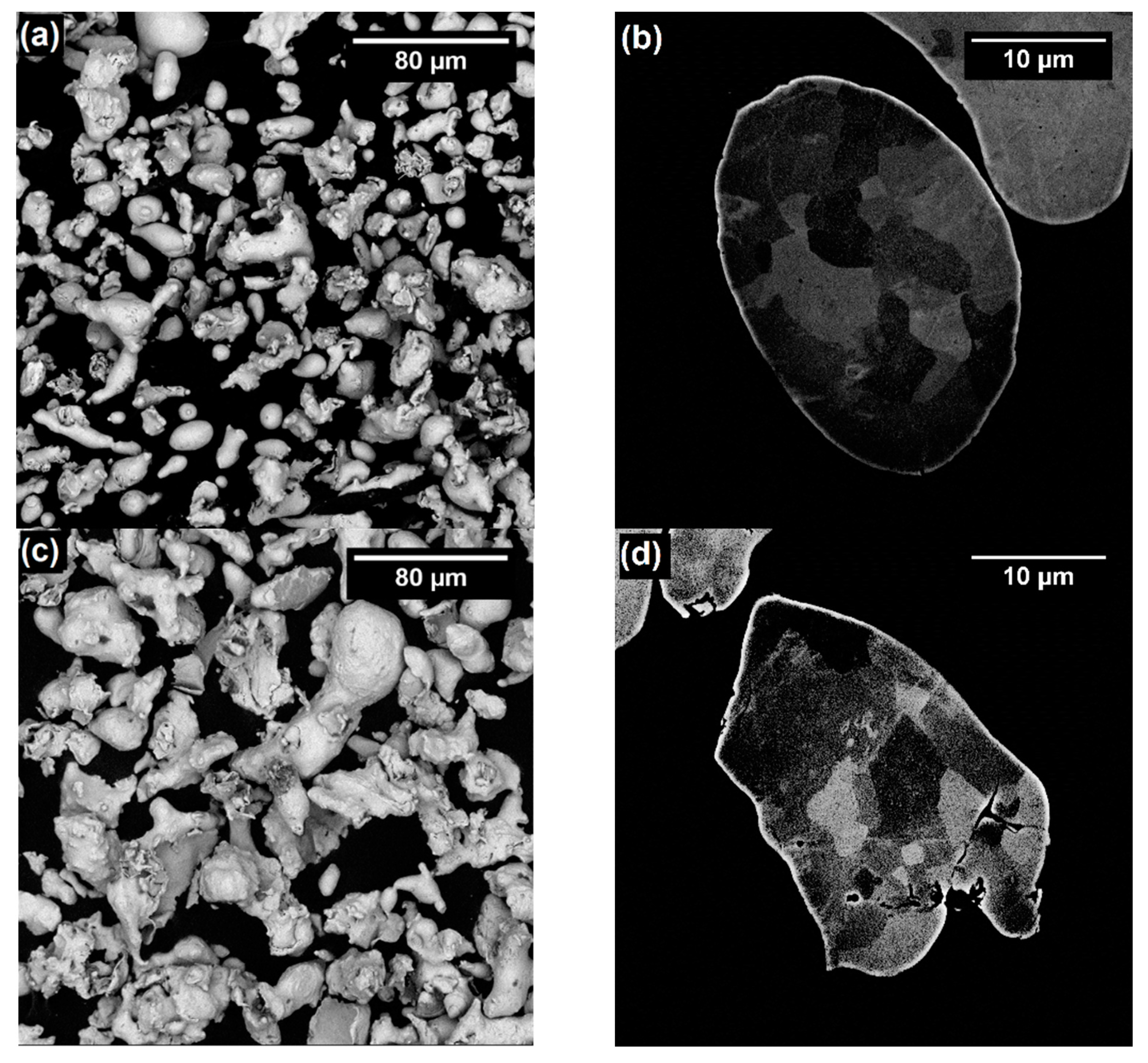
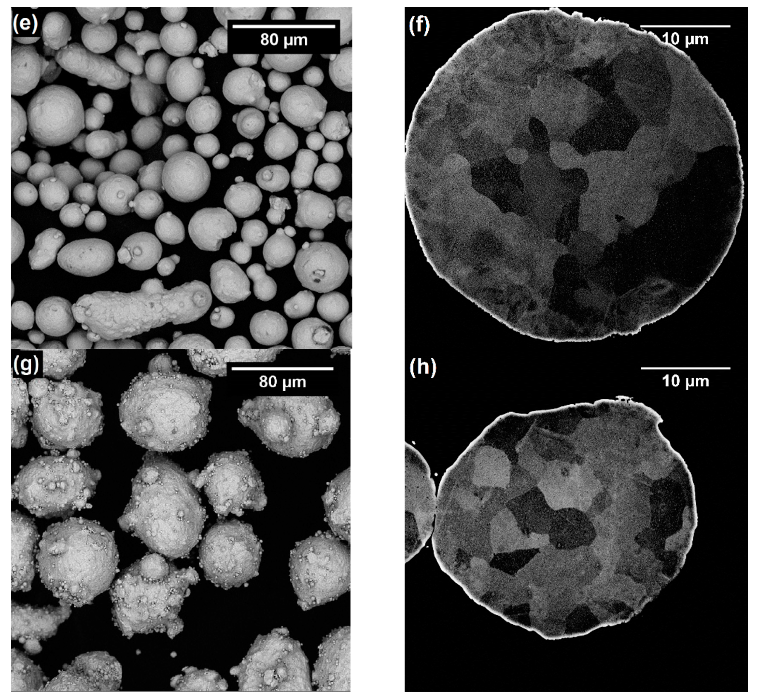
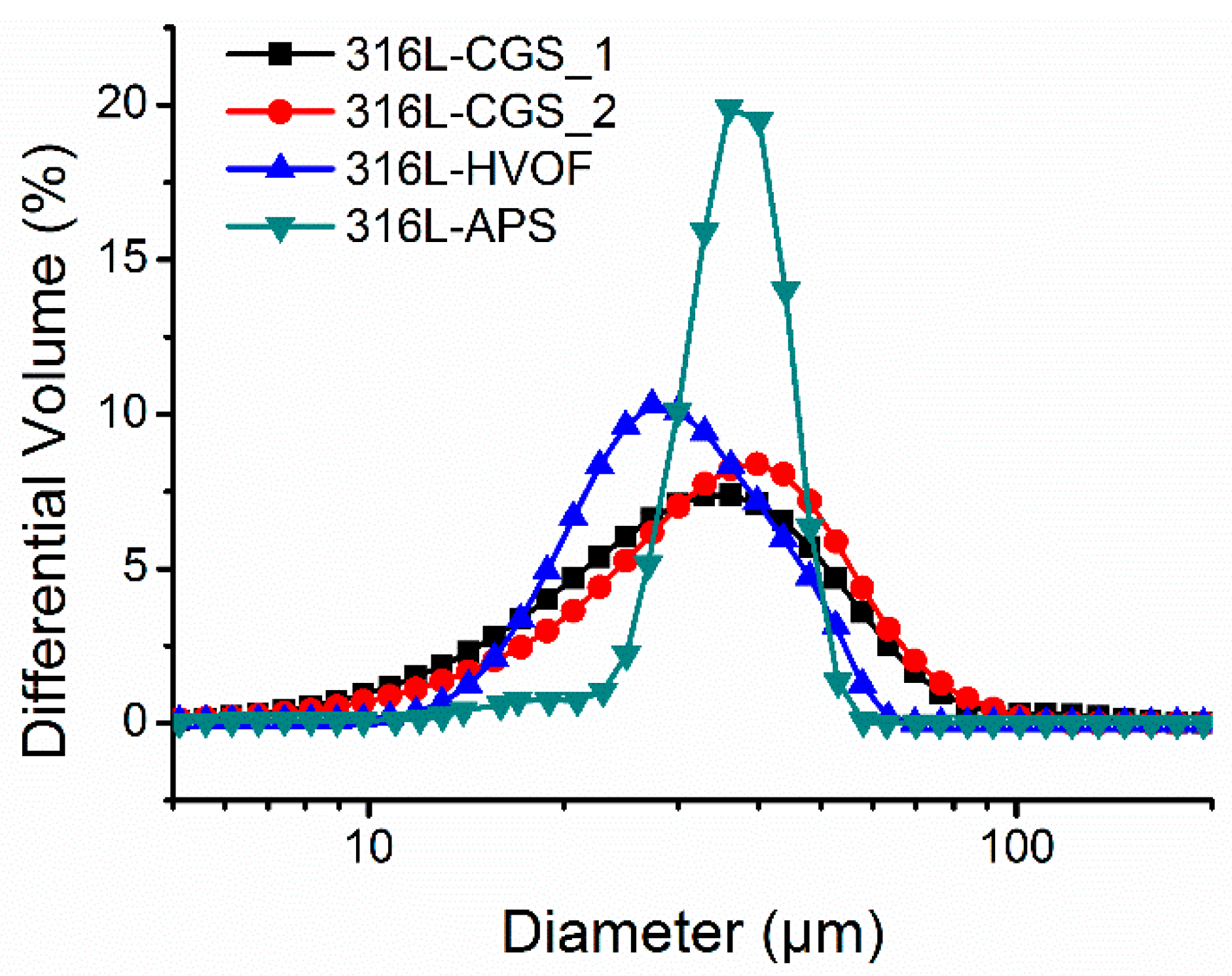
3.1. Characterization of Powders

Shown in Figure 2a–h are SEM images of the feedstock powders used in this study are shown. These images clearly show the differences in morphology found for these powders regarding their manufacturing process. As expected, the water atomized powders (316L-CGS_1 and 316L-CGS_2) show an irregular morphology, while the gas atomized powders (316L-HVOF and 316L-APS) are composed of quasi-spherical particles, with satellite particles attached to the bigger particles of the 316-APS. These differences are mentioned by Lagutkin et al. [15], who explained that the high spheroidicity of the gas atomized powders as a result of using an inert gas in the atomization process. The amount of satellite particles in gas atomized powders is attributed to the fabrication process’ parameters by Beckers et al. [14], since the satellite are particles previously solidified that collide and adhere to the bigger particles, and their formation is influenced by the particle concentration in a atomization flow, the direction of atomizing gas jets, the design of the atomizing chamber, and other parameters [14]. On the other hand, the irregular shape of water atomized powders may be attributed to the relative higher cooling rates during solidification compared to the gas atomizing process [41]. A microstructure of austenite grains was revealed by observing the powders’ cross-section in a SEM. These grains are identical to the presented by Sklyar et al. [42], with presence of smaller grain size in the smaller particles due to their faster solidification process.
In order to corroborate the chemical composition and crystallographic structure of the powders used in this study, the content of alloying elements and the identification of phases in the 316L powders was carried out by ICP and XRD, respectively. The composition of the powders is shown in Table 2, which were in agreement with the 316L reference, as expected. Only a exception was observed for 316L-APS powder, the Ni and Mo amounts closely out of range. The XRD diffractograms corresponding to all the 316L powders are shown in Figure 3 and their phase analysis indicates the presence of one only phase, austenite γ (reference code: 00-023-0298), in all of the feedstock powders.
The mentioned differences observed in the particle size between powders were confirmed by the LS technique. Figure 4 shows the particle size distribution histograms obtained by this method for all the powders. In the graphs it can be clearly observed that only the 316L-APS powder presentes a narrower particle size distribution and its volume of small particles, observed in Figure 2d, was too low and did not contributes significantly for its histogram in Figure 2d, while for the other three powders, the curves were quite wide. In case of the water-atomized powders, 316L-CGS_1 and 316L-CGS_2, this result is common result, since the particle size distribution curve obtained by LS might under- and over-estimate the volume of the particles due to the irregular shape of the particles. Distribution size parameters (d10 and d90) and apparent density of the powders are included in Table 3.
The flow rate and the flowability of the powders was also measured by means of a Hall funnel, ASTM B213-03 [30], are indicated in Table 3. Powder flowability is an important characteristic of powders for CGS as it influences the powder feed rate that may be achieved in the CGS equipment. In this respect, an increase of the powder flow rate of the would lead to an increase of the powder feed rate on the same spraying conditions, as confirmed in Table 3, with the highest value of apparent density, flow rate, and powder feed rate seen for the same powder, 316L-HVOF. Bearing in mind that all the powders had been sprayed under identical spraying conditions, feed rate may show a significant effect on the deposition efficiency and coating characteristics, as it will determine the amount of particles introduced into the powder laden jet, and, hence, it will affect the final particle temperature and/or velocity. The lower values presented in Table 3 for the water atomized powders, 316L-CGS_1 and 316L-CGS_2, are related to the shape of the particles, since the spherical shape tends to have higher flowability, and to the d90 value of particle size distribution, which is 60 μm for the water atomized powders and 47 μm for the gas atomized powders.
From the comparison of the SEM and LS data with the flow rate results for each powder, it can be interpreted that the morphology and size of the powder particles clearly affect to the flowability of the powders. Thus, the quasi-spherical powders showed a higher flow rate than the water-atomized materials as it is widely accepted that an irregular shape of particles has a detrimental effect on its flow rate. Unexpectedly, the flow rate measured for the 316L-APS powder (with the narrowest particle size distribution) points out that this material did not show higher flowability than the 316L-HVOF powder. This result can be justified by the presence of the satellite particles on the surface of the biggest particles among the samples, Figure 2, which significantly decreased its flowability. The powder feeding rate achieved by each powder under identical spraying conditions is included in Table 3.

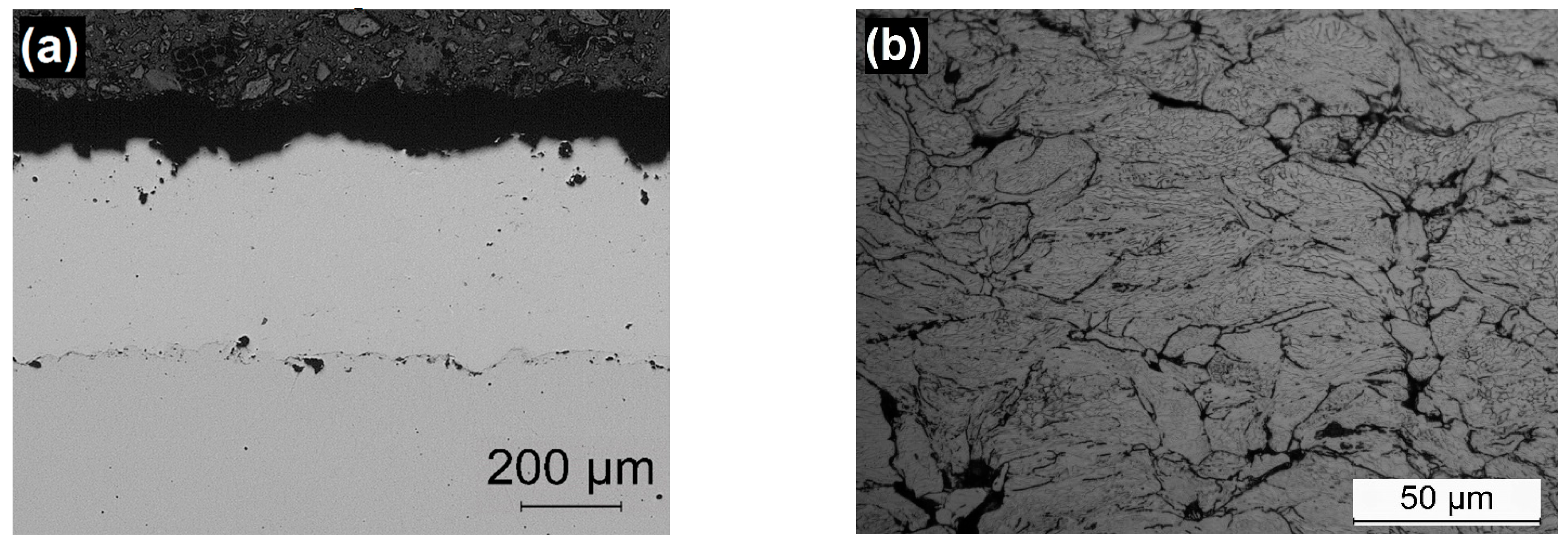
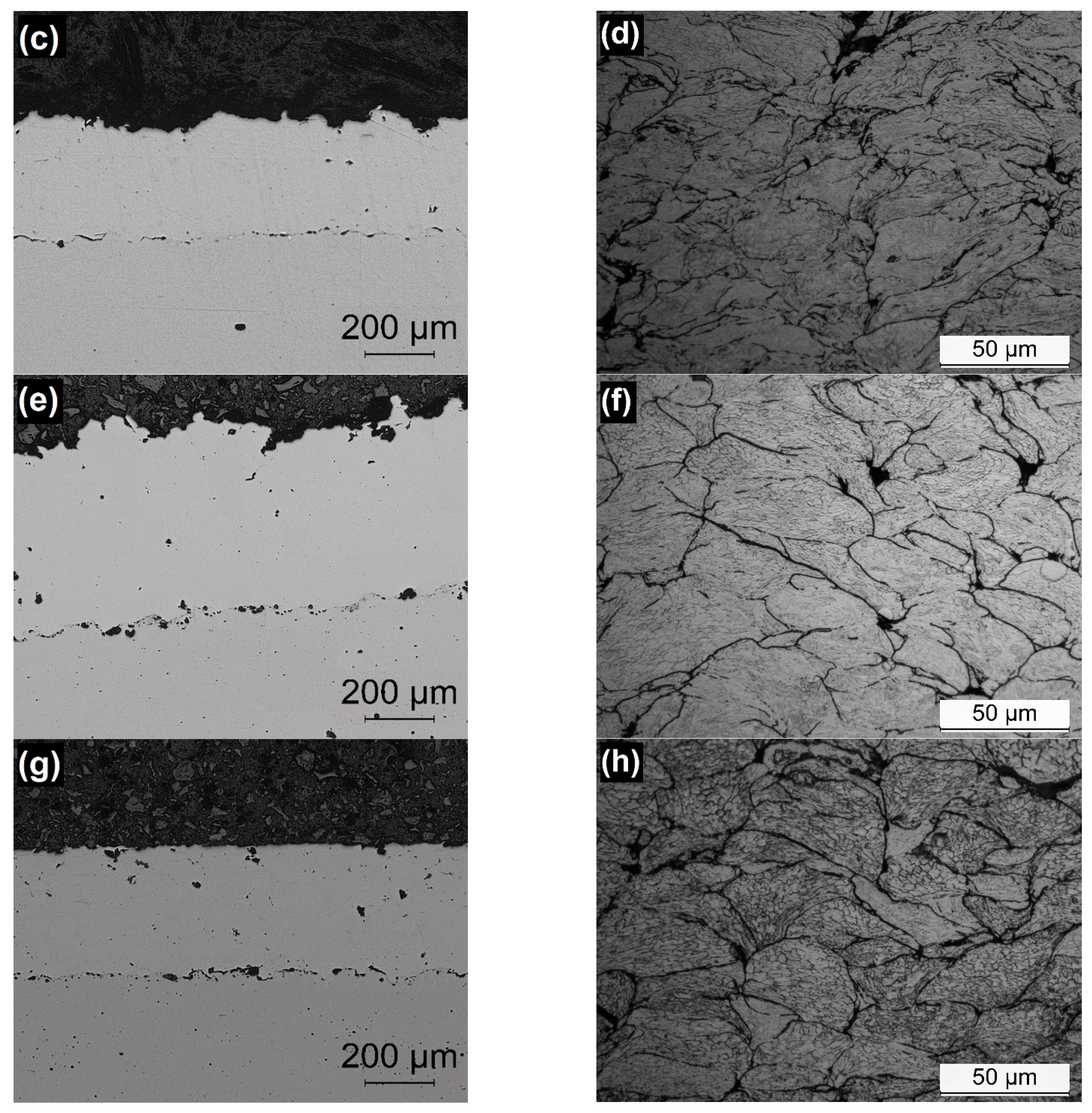
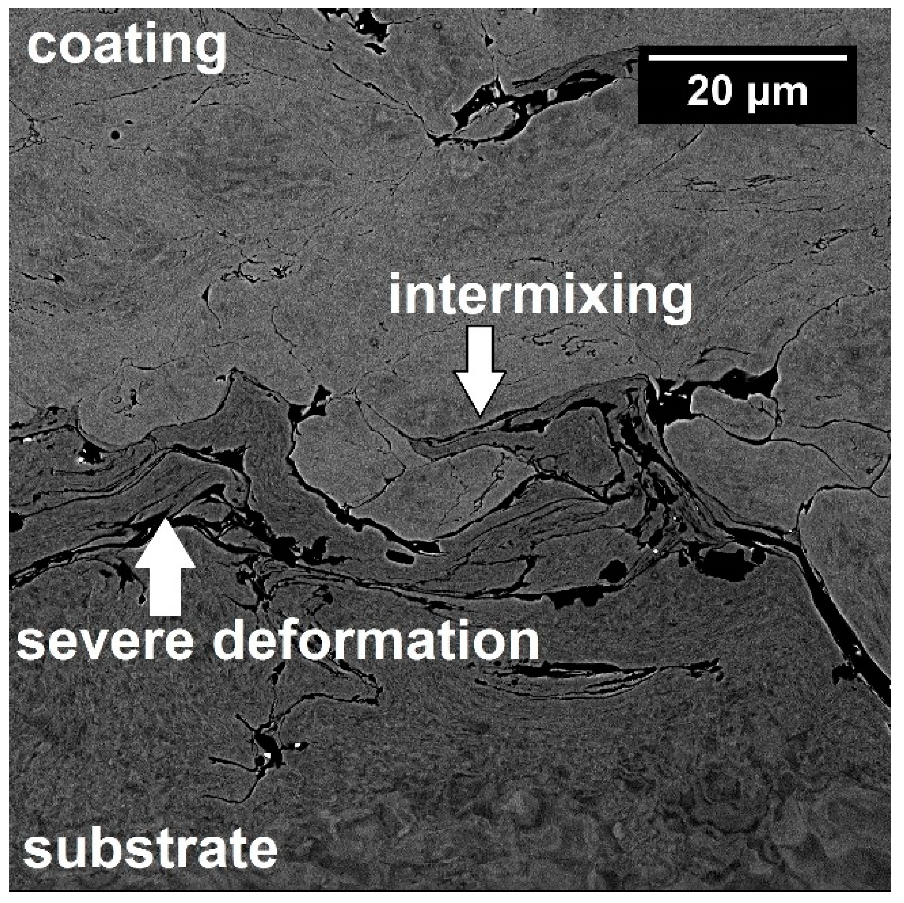
3.2. Characterization of Coatings

The OM cross section images recorded for the CGS coatings deposited in this study are shown in Figure 5a–h. In these images, it can be observed that all the coatings showed the densified and typical structure of CGS coatings, with the deformed powder particles forming the lamellae/splats structure, clearly seen in the etched samples. The etching also revealed the severe grain deformation in the periphery of the particles. In addition, the Figure 6 presents an example of interface substrate/coating revealing the severe deformation of the carbon steel substrate and the intermixing between the coating and substrate materials, which are anchoring mechanisms of the CGS coatings [21,22,23]. The coating/substrate interfaces also did not present inclusions of alumina from sandblasting preparation process nor delamination.
For comparative reasons, the porosity of all the coatings was calculated by means of image analysis and the values obtained are included in Table 4. It is worth indicating that these porosity percentages are calculated as a mean value of ten images for each material, and for this reason, the OM images shown in Figure 5 do not necessarily represent this mean value. It is accepted that the density of the coating and deposition efficiency are directly related to the particle size distribution, shape of the feedstock particles, and CGS parameters [44], as the amount of small particle composing the size distribution had severe influence on the porosity of CGS coatings, as related by Spencer and Zhang [45], presenting increasing of porosity with the powder d10 value. In this respect, coatings showing high density and deposition efficiency would be expected when the material used has a smaller d10 value in the particle size distribution and spherical morphology, favoring their flattening and homogeneity of splats phase in the coating, when compared to coatings obtained by irregular shape feedstock powders [44].
All the coatings prepared in this study showed porosity percentages lower than 0.5%, regardless of the raw material features. These values of porosity are even lower than the values presented by other authors: 1.9% [27], 2.2% [46], 3.3% [8], and 1.86% [5], for identical coating materials and process. Even as the differences between coatings are not significant, the porosity results suggests that for those 316L powders, higher coating density may be achieved when water atomized powders (irregular morphology), with lower d10 value than the spheroidal, are used for CGS deposition. The powder 316L-APS, even with higher powder feed rate and apparent density, 0.50 g·s−1 and 3.73 ± 0.01 g.cm−3, respectively, presented the lowest deposition efficiency, 80%, which resulted in the thinnest coating, 381 ± 12 μm. This is justified by the particle distribution and highest d10 value, 29 μm, which influenced reducing the particle energy at the impact on the substrate, and consequently the particle flattening and anchoring.
To complete the characterization of the coatings, the microhardness and adhesion strength of these 316L CGS coatings were also analyzed. The average values of microhardness measured for the coatings are shown in Table 4. They did not reveal significant differences among the different coatings, and are close to the mean values obtained by other authors: 358 HV [12], 370 HV [6], and 325 HV [47]. The CGS hardness values should be compared to other thermally sprayed 316L coatings: 190 HV [48] for flame spraying, 270 HV [48] and 312 HV [49] for HVOF, 325 HV for arc spraying [50], and 262 HV for APS [49]. The CGS process characteristics of lower temperature and higher velocity of particles than other processes justify its higher coating hardness, since its higher particles’ velocity promotes the increasing in hardness due to their plastic strain hardening [51], and the relative low temperature prevents the material recrystallization, thus enabling the ASI mechanism, as explained by Sun et al. [18]. In addition, all the coatings show a hardness in the range to that reported for 316L bulk materials, 350 HV0.3, approximately. It is worth underlining that the tests carried out onto the cross-section of all coatings did not present significant variation or gradient in the microhardness values from the interface substrate/coating to the top surface of the coating. These data are in agreement with the information previously interpreted from the microstructure characterization, which suggested no difference in porosity and particle-to-particle cohesion for all the 316L CGS coatings. Additionally, the indentation marks on the coatings are presented in Figure 7, showing that no cracks growing is generated from these marks, legitimating the measures.
As mentioned, the adhesion strength of the coatings was also measured and the data collected are included in Table 4. In addition, all the coating show adhesive failure between coating and substrate, since all of the coatings were completely detached from the substrate. The adherence of 316L CGS coatings is presented with a wide range of values in the literature: 53 MPa [46], 60 MPa [52], 80 MPa [53], and 13 MPa [54]. Comparing these references with Table 4, all of the studied 316L CGS coatings presented relative low values, even lower to 5 MPa for the 316L-APS coating. In spite of this, significant differences are shown between coatings, which can be ordered in terms of adherence as follows 316L-CGS_1 316L-CGS_2 316L-HVOF 316L-APS. These differences between all the coatings might indicate that better adhesion of particles to the substrate is achieved for the water atomized 316L-CGS_1 powder. This material also showed the higher deposition efficiency, which had been related with a higher particle velocity. Thus, the adhesion results will suggest that this powder would reach the higher particle temperature, favoring the particle plastic deformation during the impact and, as a result, the anchoring of the coating to the substrate.

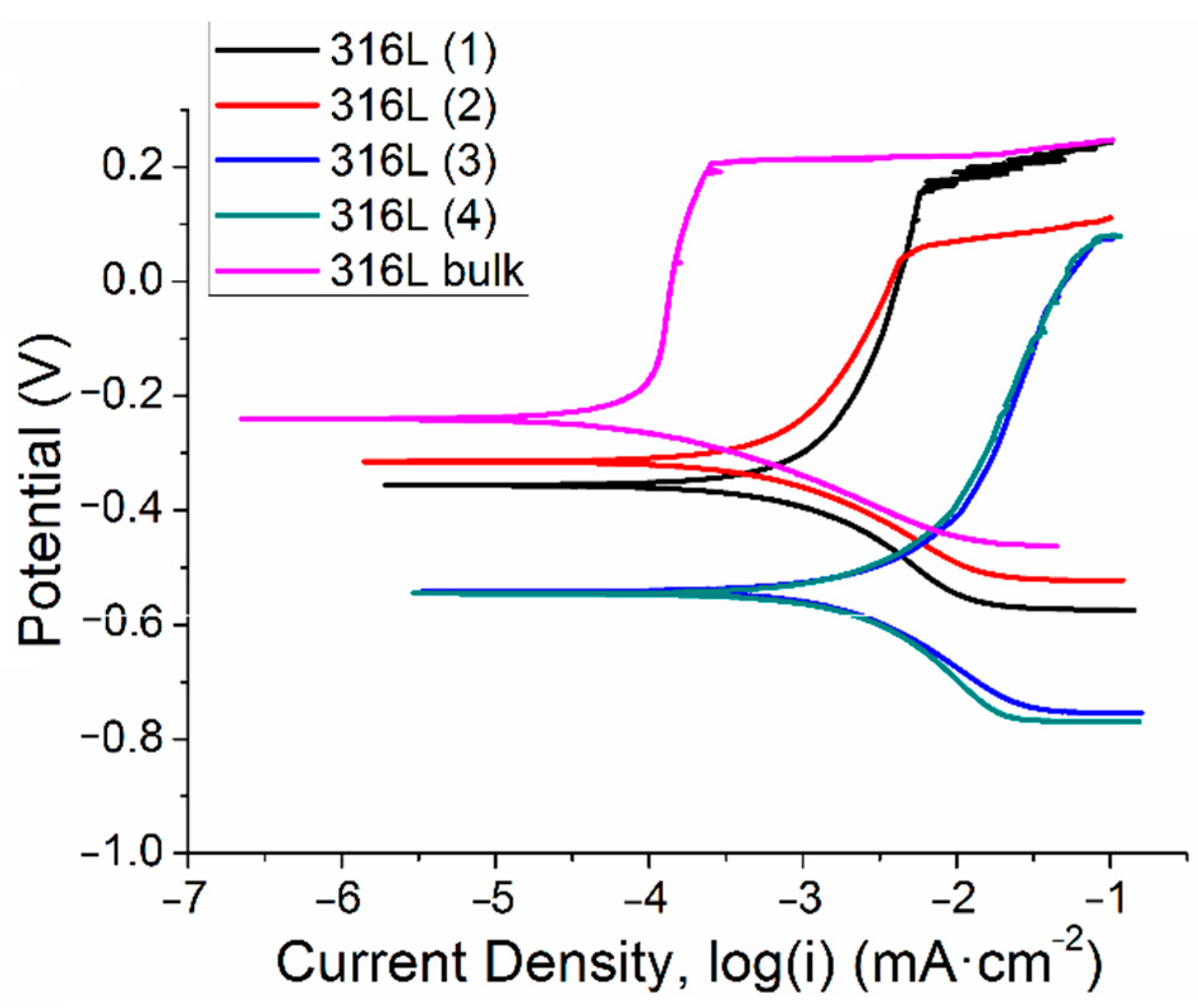
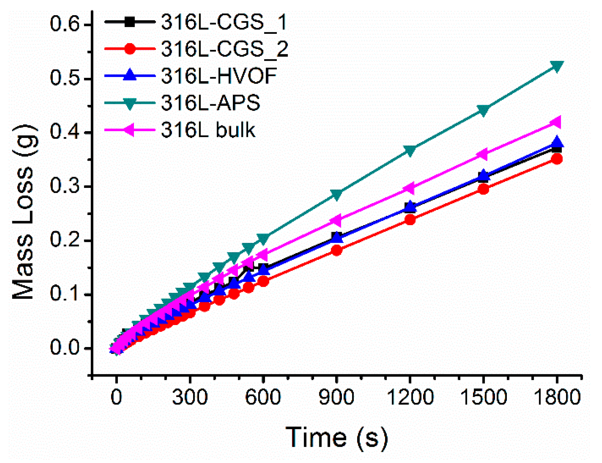
3.3. Corrosion Performance Testing

For the evaluation of the performance of theses coatings in a corrosive media, potentiodynamic experiments were conducted with all the CGS coatings. The polarization curves obtained in these experiments are shown in Figure 8. In this figure, the polarization curve measured for a 316L bulk component is also included for comparative reasons. From these curves, Ecorr and Icorr values characteristic for each coating were inferred. A significant difference in these parameters can be observed between coatings, as the 316L coatings obtained by means of the water atomized powders had corrosion potentials and current values closer to the 316L bulk reference than the gas atomized powders. This might suggest that the water atomized powders lead to the deposition of more compact coatings, which allows eliminating the effect of the substrate on the polarization response.
All the curves obtained for the 316L CGS coatings show the typical evolution expected for 316L materials. Looking at the anodic side of the polarization curve, it is observed that all the coatings showed a passivation region starting at low anodic potential. In agreement with Ecorr and Icorr values, the CGS show a higher current intensity in this passivation region than that shown by the 316L bulk. This clearly indicates that, although in all the cases the coating is passivated, the 316L will be corroded or consumed at a higher rate than for the benchmark material. As previously observed, the water atomized powders allow depositing coating with a lower passive current intensity than the gas atomized precursors.
Despite the differences observed between coatings and 316L bulk material, it is worth indicating that the 316L-CGS_1 coatings showed an Epitting value very close to that observed for the reference material, indicating that the passive layer of this coating remains stable up to the identical anodic polarization for these two materials.
From these results (Table 5), it cannot be suggested the reparation of any 316L part CGS as a promising solution considering the great performance differences between bulk material and CGS coatings. In this respect, the differences in Ecorr indicate that the incorporation of this 316L layer to a 316L surface may generate galvanic couples which will worsen the resistance of this part to the corrosive media, accelerating its degradation and mass loss [55,56]. Anyway, comparing the results between water atomized (316L-CGS_1 and 316L-CGS_2) and gas atomized (316L-HVOF and 316L-APS) powders, it is clear that the first ones are more resistant to corrosion than those obtained with an ideal spherical powder.

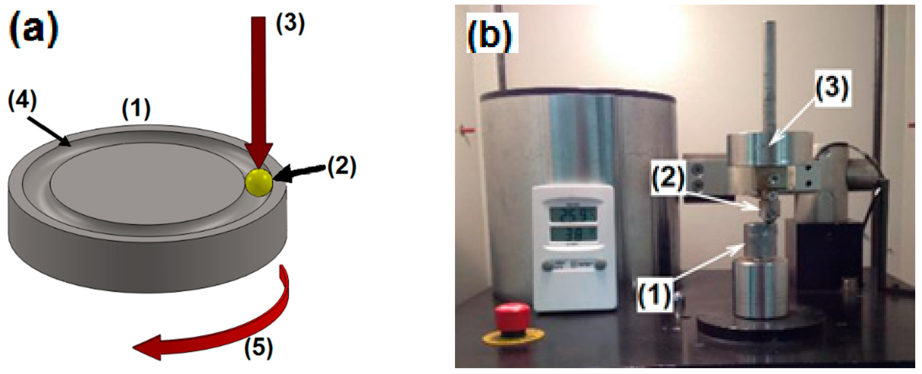
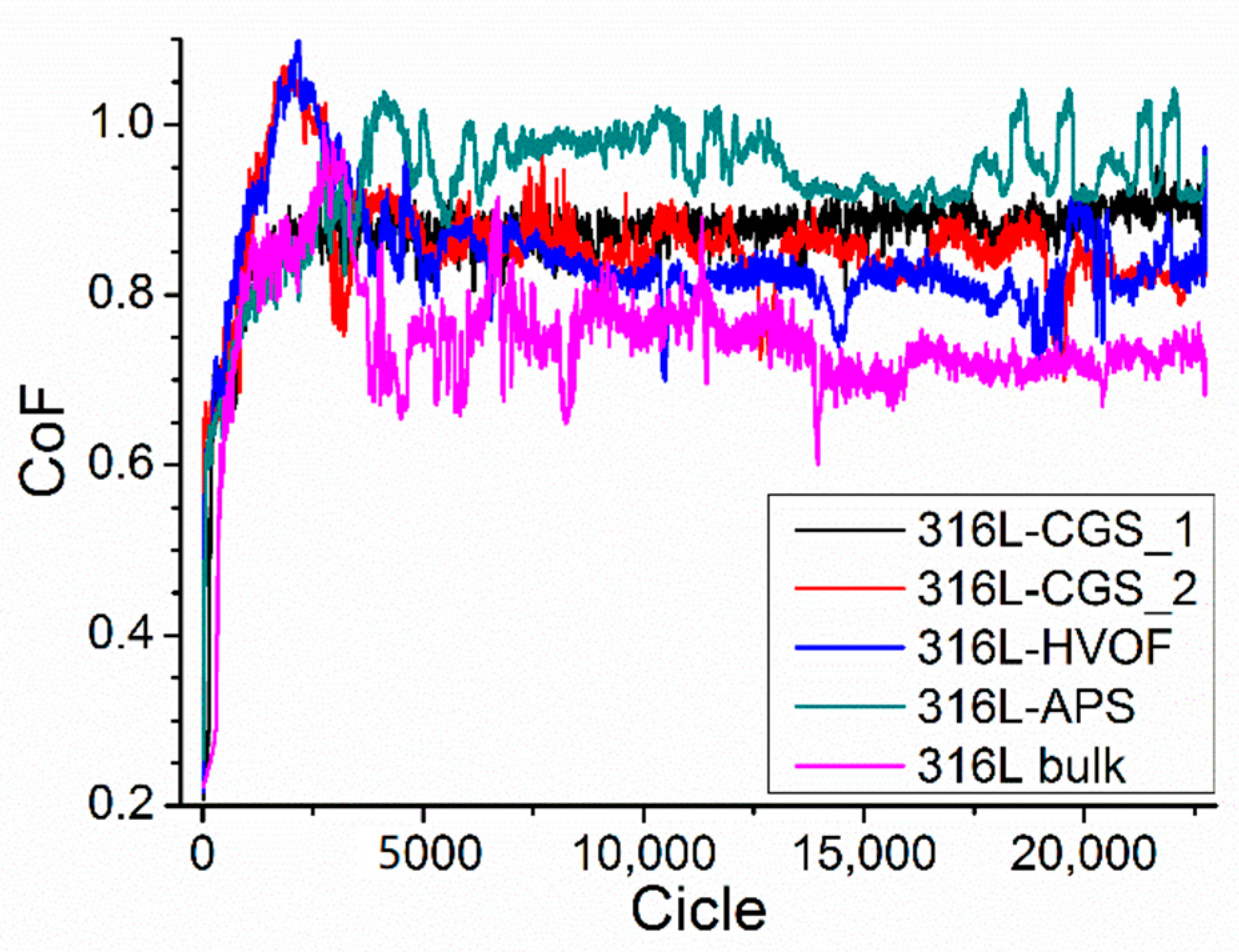
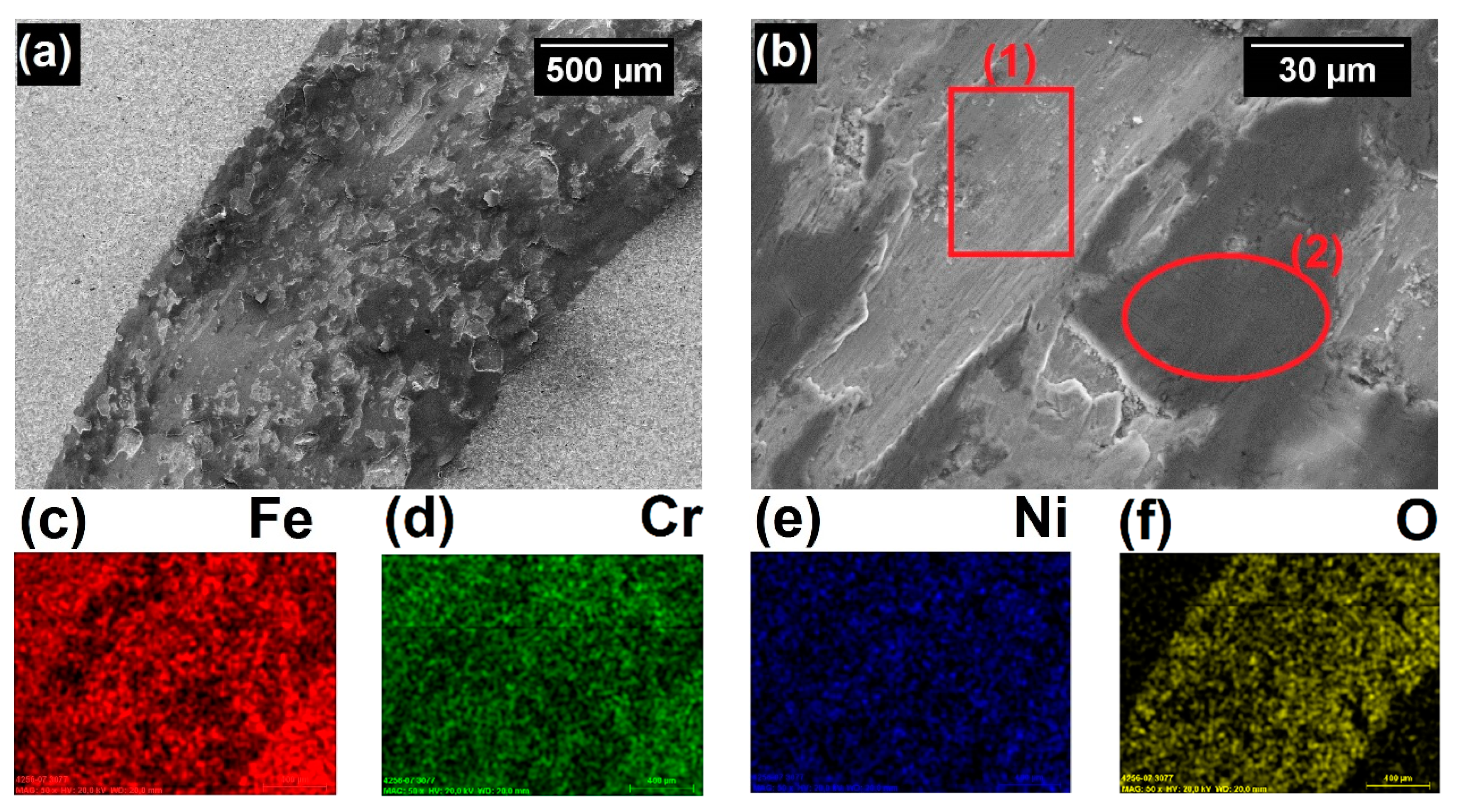
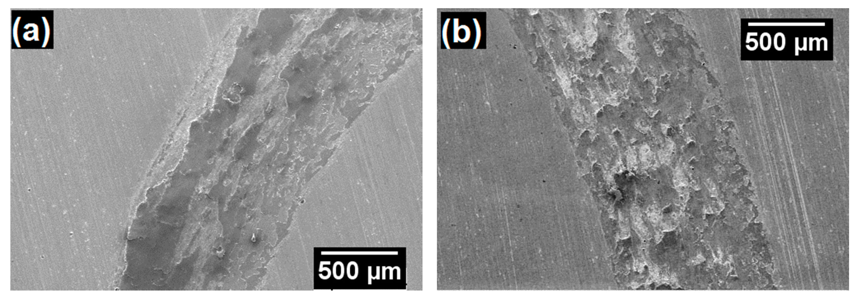
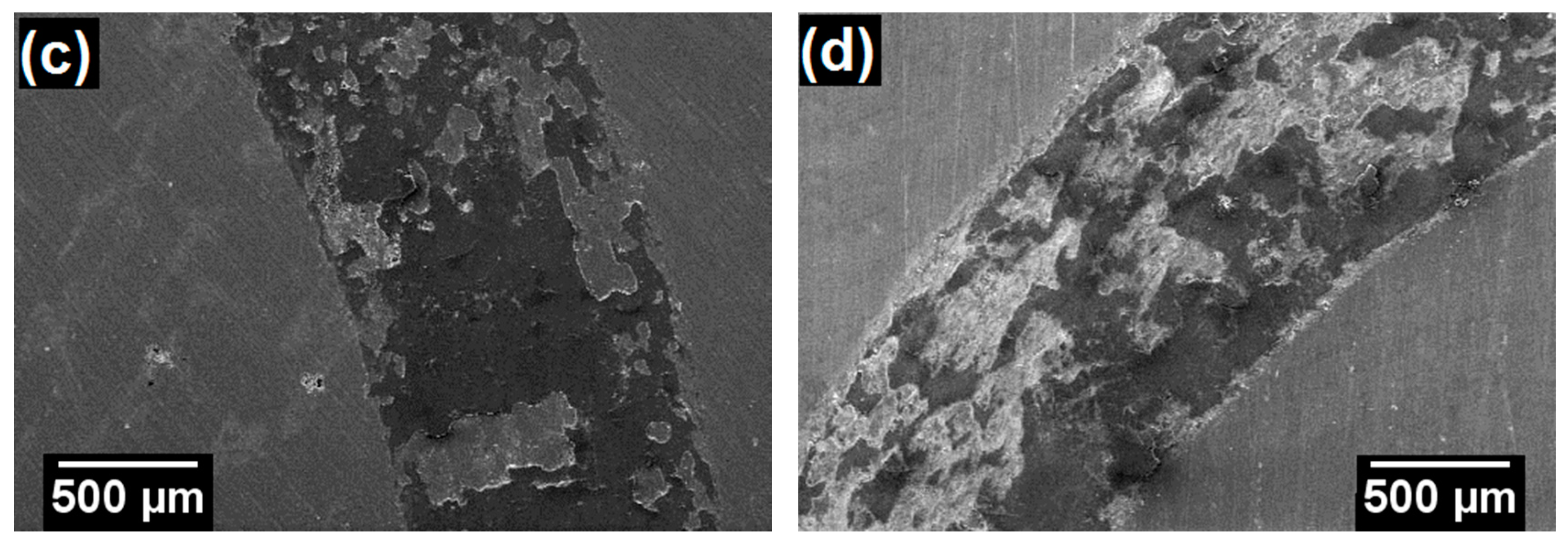
3.4. Tribological Behavior Testing

The coefficient of friction (CoF) between a WC-Co counterpart and the 316L CGS coatings was measured by means of ball-on-disk experiments. Figure 9 presents the evolution of the CoF obtained during the experiment for all the coatings and a 316L bulk material. The CoF values calculated at the end of the experiment, when the system reached a stationary behavior are included in Table 6. Similar CoF were measured for all the coatings prepared by CGS, independently of the powder used for their deposition. The 316L bulk CoF, 0.746, is close to results seen in literature with the same testing load, 0.7 [57] and 0.8 [58]; however, the CoF of all the coatings were higher than the bulk, with the highest CoF for the 316L-APS, 0.934.
The wear mechanism of the coating and bulk samples was partially abrasive type, with typical furrows in the direction of the ball relative movement, indicated as area (1) in Figure 10b. Some debris act as a third body during the sliding wear and these materials are extensively deformed and adhered to the worn surface of wear track, presented as area (2) in Figure 10b, which refers to adhesive type wear mechanism. The wear tracks on the coatings samples are presented in Figure 11. The ratio of abrasive/adhesive type wear was higher for the bulk than for the coatings, prevailing the abrasive mode. The EDS mapping of the coating and bulk samples revealed the oxidation of the debris adhered to the wear track, as exemplified by the 316L bulk analysis in Figure 10c–f. The sample 316L-APS had the highest friction wear rate, 2.23 × 10⁻⁴ mm3·N−1·m−1, while the 316L-CGS_2 had the lowest one, 1.25 × 10⁻⁴·mm3·N−1·m−1; however, this discrepancy of values is too small and the materials presented very similar friction performance.
Shown in Figure 12 the mass loss measured for the 316L CGS coatings under abrasive conditions, by means of dry rubber wheel tests are shown. In addition, in Table 6 the wear rate calculated for each coating from the mass loss values obtained in these experiments is included. From the comparison of these results, it can be interpreted that the coatings obtained with the water atomized (316L-CGS_1 and 316L-CGS_2) and gas atomized (316L-HVOF) powders allow obtaining 316L coatings with an abrasion resistance even higher than a 316L bulk material.
The abrasion resistance of a material is directly related to its Young´s modulus (E), hardness, toughness, and compactness as presented by Fu, Li, and Li [59]. According to this, the close values for the abrasion results on the rubber wheel testing, for these three coatings, 316L-CGS_1, 316L-CGS_2, and 316L.HVOF, can be explained, since these CGS layers, showed very low porosity and similar hardness to the bulk material. Finally, the 316L-APS coating showed the lower abrasion resistance, which can be directly related to its physical properties, as this was the coating with the highest porosity and the lowest adhesion strength among the coatings prepared.

4. Conclusions

Four different 316L powders were evaluated to be used as feedstock for CGS process. The water atomized powders (316L-CGS_1 and 316L-CGS_2) presented irregular morphology, lower apparent density, flow rate, and powder feed rate than the gas atomized powders (316L-HVOF and 316L-APS), which had quasi-spherical morphology.
The coatings obtained by CGS with these powders were thick and dense, with porosity lower than 0.6%. The coatings hardness had values close to the 316L bulk, 350 HV, and their morphologies presented severe grain deformation on the starting powders microstructure. The coatings produced from water atomized powders had significant higher adhesion than the gas atomized ones; however this distinction was not clear for the deposition efficiency, which was above 80% for all the materials.
The coatings produced from water atomized powders had potential of corrosion and polarization resistance closer to the 316L bulk than the gas atomized ones. But this tendency was not evident for the wear performance, CoF, abrasion rate, and friction wear rate. The 316L-APS presented the worst performance for all of the performance testing.
Considering the results obtained in this comparative study, it can be concluded that there is no particular advantage to using gas atomized 316L powders over water atomized 316L powders. Thus, the four 316L feedstock powders tested, can be ranked as adequate for CGS technology as follows: 316L-CGS_1 316L-CGS_2 316L-HVOF 316L-APS.

Author Contributions

Conceptualization, J.S.; funding acquisition, J.S. and I.G.C.; investigation, R.F.V. and A.S.; methodology, R.F.V., A.S., and J.S.; project administration, I.G.C.; writing—original draft preparation, R.F.V., A.S., J.S., and V.A.; writing—review and editing, R.F.V., J.S., and V.A.; supervision, I.G.C. All authors have read and agreed to the published version of the manuscript.

Funding

The authors thank the Spanish MINECO (MAT2016 46755-R), Generalitat de Catalunya (SGR-1777) and the support of European Regional Development Fund of the European Union in the framework of the Operational Program (FEDER-Catalonia 2014-2020).

Data Availability Statement

The data presented in this study are available on request from the corresponding author.

Conflicts of Interest

The authors declare no conflict of interest. The funders had no role in the design of the study; in the collection, analyses, or interpretation of data; in the writing of the manuscript, or in the decision to publish the results.

References

  1. Schweitzer, P.A. Paint and Coatings: Application and Corrosion Resistance; CRC Press: Boca Raton, FL, USA, 2006; ISBN 9781574447026. [Google Scholar]
  2. Dogan, H.; Findik, F.; Oztarhan, A. Comparative study of wear mechanism of surface treated AISI 316L stainless steel. Ind. Lubr. Tribol. 2003, 55, 76–83. [Google Scholar] [CrossRef]
  3. Chavan, N.M.; Kiran, B.; Jyothirmayi, A.; Phani, P.S.; Sundararajan, G. The corrosion behavior of cold sprayed zinc coatings on mild steel substrate. J. Therm. Spray Technol. 2013, 22, 463–470. [Google Scholar] [CrossRef]
  4. Łatka, L.; Pawłowski, L.; Winnicki, M.; Sokołowski, P.; Malachowska, A.; Kozerski, S. Review of functionally graded thermal sprayed coatings. Appl. Sci. 2020, 10, 5153. [Google Scholar] [CrossRef]
  5. Cortés, R.; Garrido, M.Á.; Poza, P.; Martos, A.; Dosta, S.; García, I. Cold sprayed coatings for repairing damaged metallic structures. Key Eng. Mater. 2019, 813, 74–79. [Google Scholar] [CrossRef]
  6. Adachi, S.; Ueda, N. Wear and corrosion properties of cold-sprayed AISI 316L coatings treated by combined plasma carburizing and nitriding at low temperature. Coatings 2018, 8, 456. [Google Scholar] [CrossRef] [Green Version]
  7. Dikici, B.; Yilmazer, H.; Ozdemir, I.; Isik, M. The effect of post-heat treatment on microstructure of 316L cold-sprayed coatings and their corrosion performance. J. Therm. Spray Technol. 2016, 25, 704–714. [Google Scholar] [CrossRef]
  8. Yin, S.; Cizek, J.; Yan, X.; Lupoi, R. Annealing strategies for enhancing mechanical properties of additively manufactured 316L stainless steel deposited by cold spray. Surf. Coatings Technol. 2019, 370, 353–361. [Google Scholar] [CrossRef]
  9. Assadi, H.; Kreye, H.; Gärtner, F.; Klassen, T. Cold spraying – A materials perspective. Acta Mater. 2016, 116, 382–407. [Google Scholar] [CrossRef] [Green Version]
  10. Rokni, M.R.; Nutt, S.R.; Widener, C.A.; Champagne, V.K.; Hrabe, R.H. Review of relationship between particle deformation, coating microstructure, and properties in high-pressure cold spray. J. Therm. Spray Technol. 2017, 26, 1308–1355. [Google Scholar] [CrossRef]
  11. Tului, M.; Bartuli, C.; Bezzon, A.; Marino, A.L.; Marra, F.; Matera, S.; Pulci, G. Amorphous steel coatings deposited by cold-gas spraying. Metals 2019, 9, 678. [Google Scholar] [CrossRef] [Green Version]
  12. Villa, M.; Dosta, S.; Guilemany, J.M. Optimization of 316L stainless steel coatings on light alloys using Cold Gas Spray. Surf. Coatings Technol. 2013, 235, 220–225. [Google Scholar] [CrossRef]
  13. Sousa, B.C.; Gleason, M.A.; Haddad, B.; Champagne, V.K.; Nardi, A.T.; Cote, D.L. Nanomechanical characterization for cold spray: From feedstock to consolidated material properties. Metals 2020, 10, 1195. [Google Scholar] [CrossRef]
  14. Beckers, D.; Ellendt, N.; Fritsching, U.; Uhlenwinkel, V. Impact of process flow conditions on particle morphology in metal powder production via gas atomization. Adv. Powder Technol. 2020, 31, 300–311. [Google Scholar] [CrossRef]
  15. Lagutkin, S.; Achelis, L.; Sheikhaliev, S.; Uhlenwinkel, V.; Srivastava, V. Atomization process for metal powder. Mater. Sci. Eng. A 2004, 383, 1–6. [Google Scholar] [CrossRef]
  16. Suri, P.; Koseski, R.P.; German, R.M. Microstructural evolution of injection molded gas- and water-atomized 316L stainless steel powder during sintering. Mater. Sci. Eng. A 2005, 402, 341–348. [Google Scholar] [CrossRef]
  17. Jeandin, M.; Rolland, G.; Descurninges, L.L.; Berger, M.H. Which powders for cold spray? Surf. Eng. 2014, 30, 291–298. [Google Scholar] [CrossRef]
  18. Sun, W.; Tan, A.W.; Wu, K.; Yin, S.; Yang, X.; Marinescu, I.; Liu, E. Post-process treatments on supersonic cold sprayed coatings: A review. Coatings 2020, 10, 123. [Google Scholar] [CrossRef] [Green Version]
  19. Ichikawa, Y.; Tokoro, R.; Tanno, M.; Ogawa, K. Acta Materialia Elucidation of cold-spray deposition mechanism by auger electron spectroscopic evaluation of bonding interface oxide fi lm. Acta Mater. 2019, 164, 39–49. [Google Scholar] [CrossRef]
  20. Sun, W.; Wei, A.; Tan, Y.; Marinescu, I.; Quan, W.; Liu, E. Adhesion, tribological and corrosion properties of cold-sprayed CoCrMo and Ti6Al4V coatings on 6061-T651 Al alloy. Surf. Coat. Technol. 2017, 326, 291–298. [Google Scholar] [CrossRef]
  21. Ko, K.H.; Choi, J.O.; Lee, H. Intermixing and interfacial morphology of cold-sprayed Al coatings on steel. Mater. Lett. 2014, 136, 45–47. [Google Scholar] [CrossRef]
  22. Bae, G.; Kumar, S.; Yoon, S.; Kang, K.; Na, H.; Kim, H.; Lee, C. Bonding features and associated mechanisms in kinetic sprayed titanium coatings. Acta Mater. 2009, 57, 5654–5666. [Google Scholar] [CrossRef]
  23. Yin, S.; Cizek, J.; Cupera, J.; Hassani, M.; Luo, X.; Jenkins, R.; Xie, Y.; Li, W.; Lupoi, R. Formation conditions of vortex-like intermixing interfaces in cold spray. Mater. Des. 2021, 200, 1–10. [Google Scholar] [CrossRef]
  24. Schmidt, T.; Gaertner, F.; Kreye, H. New developments in cold spray based on higher gas and particle temperatures. J. Therm. Spray Technol. 2006, 15, 488–494. [Google Scholar] [CrossRef]
  25. Fukanuma, H.; Ohno, N.; Sun, B.; Huang, R. In-flight particle velocity measurements with DPV-2000 in cold spray. Surf. Coatings Technol. 2006, 201, 1935–1941. [Google Scholar] [CrossRef]
  26. Jodoin, B.; Ajdelsztajn, L.; Sansoucy, E.; Zúñiga, A.; Richer, P.; Lavernia, E.J. Effect of particle size, morphology, and hardness on cold gas dynamic sprayed aluminum alloy coatings. Surf. Coatings Technol. 2006, 201, 3422–3429. [Google Scholar] [CrossRef]
  27. Adachi, S.; Ueda, N. Effect of cold-spray conditions using a nitrogen propellant gas on AISI 316L stainless steel-coating microstructures. Coatings 2017, 7, 87. [Google Scholar] [CrossRef] [Green Version]
  28. Standard Test Method for Particle Size Distribution of Metal Powders and Related Compounds by Laser Scattering; ASTM B822-02; ASTM International: West Conshohocken, PA, USA, 2002.
  29. Standard Test Method for Apparent Density of Powders using the Hall Flowmeter Funnel; ASTM B212-99; ASTM International: West Conshohocken, PA, USA, 1999.
  30. Standard Test Method for Flow Rate of Metal Powders; ASTM B213-03; ASTM International: West Conshohocken, PA, USA, 2003.
  31. Standard Guide for Metallographic Preparation of Thermal Sprayed Coatings; ASTM E1920-03; ASTM International: West Conshohocken, PA, USA, 2003.
  32. Standard Guide for Preparation of Metallographic Specimens; ASTM E3-01; ASTM International: West Conshohocken, PA, USA, 2001.
  33. ASTM B487-85 - Standard Test Method for Measurement of Metal and Oxide Coating Thickness by Microscopical Examination of a Cross Section; ASTM International: West Conshohocken, PA, USA, 2002.
  34. Standard test Methods for Determining Area Percentage Porosity in Thermal Sprayed Coatings; ASTM E2109-01; ASTM International: West Conshohocken, PA, USA, 2002.
  35. Standard Test Method for Microindentation Hardness of Materials; ASTM E384-99; ASTM International: West Conshohocken, PA, USA, 2000.
  36. Standard Test Method for Adhesion or Cohesion Strength of Thermal Spray Coatings; ASTM C633-17; ASTM International: West Conshohocken, PA, USA, 2017.
  37. Standard Test Method for Measuring Abrasion using the Dry Sand Rubber wheel Apparatus; ASTM G65-00; ASTM International: West Conshohocken, PA, USA, 2000.
  38. Standard Test Method for Wear Testing with a Pin-on-Disk Apparatus; ASTM G99-04; ASTM International: West Conshohocken, PA, USA, 2004.
  39. Standard Test Method for Conducting Potentiodynamic Polarization Resistance Measurements; ASTM G59-97; ASTM International: West Conshohocken, PA, USA, 2003.
  40. Standard Practice for Calculation of Corrosion Rates and Related Information from Electrochemical Measurements; ASTM G102-89; ASTM International: West Conshohocken, PA, USA, 1999.
  41. Hoeges, S.; Zwiren, A.; Schade, C. Additive manufacturing using water atomized steel powders. Met. Powder Rep. 2017, 72, 111–117. [Google Scholar] [CrossRef]
  42. Sklyar, M.O.; Turichin, G.A.; Klimova, O.G.; Zotov, O.G.; Topalov, I.K. Microstructure of 316L stainless steel components produced by direct laser deposition. Steel Transl. 2016, 46, 883–887. [Google Scholar] [CrossRef]
  43. Standard Aspecification for Chromium and Chromium-Nickel Stainless Steel Plate, Sheet, and Strip for Pressure Vessels and for General Applications; ASTM A240/A240M-04a; ASTM International: West Conshohocken, PA, USA, 2004.
  44. Wong, W.; Vo, P.; Irissou, E.; Ryabinin, A.N.; Legoux, J.; Yue, S. Effect of particle morphology and size distribution on cold-sprayed pure titanium coatings. J. Therm. Spray Technol. 2013, 22, 1140–1153. [Google Scholar] [CrossRef]
  45. Spencer, K.; Zhang, M.X. Optimisation of stainless steel cold spray coatings using mixed particle size distributions. Surf. Coatings Technol. 2011, 205, 5135–5140. [Google Scholar] [CrossRef]
  46. Chu, X.; Che, H.; Teng, C.; Vo, P.; Yue, S. A multiple particle arrangement model to understand cold spray characteristics of bimodal size 316L/Fe powder mixtures. Surf. Coatings Technol. 2020, 381, 1–8. [Google Scholar] [CrossRef]
  47. Wang, Y.; Adrien, J.; Normand, B. Porosity characterization of cold sprayed stainless steel coating using three-dimensional X-ray microtomography. Coatings 2018, 8, 326. [Google Scholar] [CrossRef] [Green Version]
  48. Mindivan, H.; Kale, A.; Berse, U.; Samur, R. A comparative study of thermal sprayed AISI 316L stainless steel coatings. El-Cezerî J. Sci. Eng. 2017, 4, 127–134. [Google Scholar]
  49. Zhao, L.; Lugscheider, E. Influence of the spraying processes on the properties of 316L stainless steel coatings. Surf. Coatings Technol. 2002, 162, 6–10. [Google Scholar] [CrossRef]
  50. Li, Q.; Song, P.; Ji, Q.; Huang, Y.; Li, D.; Zhai, R.; Zheng, B.; Lu, J. Microstructure and wear performance of arc-sprayed Al/316L stainless-steel composite coating. Surf. Coatings Technol. 2019, 374, 189–200. [Google Scholar] [CrossRef]
  51. Luzin, V.; Spencer, K.; Zhang, M.X. Residual stress and thermo-mechanical properties of cold spray metal coatings. Acta Mater. 2011, 59, 1259–1270. [Google Scholar] [CrossRef]
  52. Maestracci, R.; Sova, A.; Jeandin, M.; Malhaire, J.M.; Movchan, I.; Bertrand, P.; Smurov, I. Deposition of composite coatings by cold spray using stainless steel 316L, copper and Tribaloy T-700 powder mixtures. Surf. Coatings Technol. 2016, 287, 1–8. [Google Scholar] [CrossRef]
  53. Sova, A.; Grigoriev, S.; Okunkova, A.; Smurov, I. Cold spray deposition of 316L stainless steel coatings on aluminium surface with following laser post-treatment. Surf. Coatings Technol. 2013, 235, 283–289. [Google Scholar] [CrossRef]
  54. Xie, Y.; Planche, M.P.; Raoelison, R.; Liao, H.; Suo, X.; Herve, P. Effect of substrate preheating on adhesive strength of SS 316L cold spray coatings. J. Therm. Spray Technol. 2016, 25, 123–130. [Google Scholar] [CrossRef]
  55. Pukasiewicz, A.G.M.; Sucharski, G.B.; Siqueira, I.B.A.F.; de Andrade, J.; Váz, R.F.; Procopiak, L.A.J. Corrosion resistance of iron-based alloy coatings deposited by HVOF process. In Proceedings of the ITSC 2019 - Proceedings of the International Thermal Spray Conference, Yokohama, Japan, 26–29 May 2019; Azarmi, F., Lau, Y., Veilleux, J., Widener, C., Toma, F., Koivuluoto, H., Balani, K., Li, H., Shinoda, K., Eds.; ASM International: Yokohama, Japan, 2019; pp. 359–368. [Google Scholar]
  56. Zhang, X.G. Galvanic corrosion. In Uhlig’s Corrosion Handbook; Revie, R.W., Ed.; Wiley: Hoboken, NJ, USA, 2011; pp. 123–143. ISBN 9780470080320. [Google Scholar]
  57. Fellah, M.; Labaız, M.; Assala, O.; Iost, A.; Dekhil, L. Tribological behaviour of AISI 316L stainless steel for biomedical applications. Tribology 2013, 7, 135–149. [Google Scholar] [CrossRef]
  58. Qin, W.; Kang, J.; Li, J.; Yue, W.; Liu, Y.; She, D.; Mao, Q.; Li, Y. Tribological behavior of the 316L stainless steel with heterogeneous lamella structure. Materials 2018, 11, 839. [Google Scholar] [CrossRef] [PubMed] [Green Version]
  59. Fu, L.; Li, L.; Li, D.Y. Further look at correlation between ASTM G65 rubber wheel abrasion and pin-on-disc wear tests for data conversion. Tribol.-Mater. Surfaces Interfaces 2013, 7, 109–113. [Google Scholar] [CrossRef]
Figure 1. (a) scheme and (b) equipment for ball-on-disk testing, (1) sample, (2) ball, (3) load, (4) wear path on sample, and (5) rotation direction of sample.
Coatings 11 00168 g001
Figure 2. SEM of three dimensional and etched cross section images of powders at 1000× and 7000×, respectively. (a,b) 316L-CGS_1, (c,d) 316L-CGS_2, (e,f) 316L-HVOF, and (g,h) 316L-APS.
Coatings 11 00168 g002aCoatings 11 00168 g002b
Figure 3. XRD patterns of the 316L feedstock powders.
Coatings 11 00168 g003
Figure 4. Particle distribution of the 316L feedstock powders.
Coatings 11 00168 g004
Figure 5. OM of cross-sectional image of the CGS coatings obtained at 50× as polished and 500× as etched. Powders: (a,b) 316L-CGS_1, (c,d) 316L-CGS_2, (e,f) 316L-HVOF, and (g,h) 316L-APS.
Coatings 11 00168 g005aCoatings 11 00168 g005b
Figure 6. SEM of the interface substrate/coating of 316L-CGS_1 obtained at 3000×.
Coatings 11 00168 g006
Figure 7. Marks for hardness measurements of the coatings. (a) 316L-CGS_1, (b) 316L-CGS_2, (c) 316L-HVOF, and (d) 316L-APS.
Coatings 11 00168 g007
Figure 8. Tafel slopes of 316L coatings and bulk.
Coatings 11 00168 g008
Figure 9. Results of ball-on-disk testing for 316L coatings and bulk.
Coatings 11 00168 g009
Figure 10. SEM and EDS of the 316L bulk ball-on-disk testing track. (a) 50×. (b) 1000×, where (1) is a region with abrasion-type wear marks and (2) is a region with adhesive-type wear. (cf) EDS mappings.
Coatings 11 00168 g010
Figure 11. SEM of the coatings ball on disk testing track. 50×. (a) 316L-CGS_1, (b) 316L-CGS_2, (c) 316L-HVOF, and (d) 316L-APS.
Coatings 11 00168 g011aCoatings 11 00168 g011b
Figure 12. Results of rubber wheel testing for 316L coatings and bulk.
Coatings 11 00168 g012
Table 1. Feedstock materials.
Powder IdentificationNominal Composition (wt.%)Particle Size Distribution (μm)Fabrication Process
CrNiMoMnSiFe
316L-CGS_117.6-2.70.30.8Bal.−40 + 15Water atomized
316L-CGS_218143-1Bal.−45 + 10Water atomized
316L-HVOF17122.5-2.3Bal.−45 + 11Gas atomized
316L-APS17122.521Bal.−45 + 20Gas atomized
Table 2. Chemical composition of the 316L feedstock powders. wt.%.
MaterialCrNiMoMnMgSPSiFe
316L-CGS_116.0312.272.570.520.10.50.52.0Bal.
316L-CGS_216.3211.192.160.090.10.50.52.0Bal.
316L-HVOF16.4210.122.071.370.10.50.52.0Bal.
316L-APS17.079.551.830.550.10.50.52.0Bal.
316L reference [43]16.0
18.0
10.0
14.0
2.00
3.00
2.00 max-0.030 max0.045 max0.75 maxBal.
Table 3. Particle distribution, apparent density, and flow rate of the 316L feedstock powders.
MaterialParticle Size Distribution
(µm)
MorphologyApparent Density
(g·cm−3)
Flow Rate
(g·s−1)
Powder Feed Rate
(g·s−1)
d10 *d90 **
316L-CGS_11660Irregular3.03 ± 0.019.03 ± 0.360.43
316L-CGS_21760Irregular2.86 ± 0.018.21 ± 0.490.41
316L-HVOF1947Quasi-spherical4.47 ± 0.0117.61 ± 0.400.55
316L-APS2947Quasi-spherical ***3.73 ± 0.0113.44 ± 0.650.50
* d10: 10% of the powder have size under this value; ** d90: 90% of the powder have size under this value; *** Presence of satellite particles.
Table 4. Properties of the 316L coatings.
MaterialHardness
(HV0.3)
Thickness
(µm)
Porosity
(%)
Adherence
(MPa)
Deposition Efficiency
(%)
316L-CGS_1356 ± 23420 ± 260.1 ± 0.029.4 ± 4.997
316L-CGS_2348 ± 48331 ± 280.2 ± 0.019.7 ± 2.485
316L-HVOF353 ± 44517 ± 210.2 ± 0.111.0 ± 1.992
316L-APS344 ± 25381 ± 120.4 ± 0.24.5 ± 2.180
Table 5. Results of corrosion testing and abrasion rate for 316L CGS coatings and bulk.
MaterialCurrent Density
icorr (µA·cm−2)
Potential of Corrosion
Ecorr (mV)
Polarization Resistance
Rp (kΩ)
316L-CGS_12.120−356.33236.119
316L-CGS_20.897−315.18945.640
316L-HVOF3.244−541.90915.518
316L-APS2.373−546.62714.322
316L bulk0.100−239.73850.080
Table 6. Results of ball-on-disk testing for 316L coatings and bulk.
MaterialAbrasion Rate (mm3·N−1·m−1)CoFFriction Wear Rate (mm3·N−1·m−1)
316L-CGS_11.70 × 10−40.869 ± 0.0701.651 × 10−4
316L-CGS_21.32 × 10−40.857 ± 0.0731.251 × 10−4
316L-HVOF1.60 × 10−40.841 ± 0.0771.619 × 10−4
316L-APS2.25 × 10−40.934 ± 0.0782.228 × 10−4
316L bulk1.91 × 10−40.746 ± 0.1001.692 × 10−4
Publisher’s Note: MDPI stays neutral with regard to jurisdictional claims in published maps and institutional affiliations.

