Article

Thin Films of Plasma-Polymerized n-Hexane and ZnO Nanoparticles Co-Deposited via Atmospheric Pressure Plasma Jet

1
Department of Industrial Engineering, University of Trento, Via Sommarive–9, Povo, I-38123 Trento, Italy
2
Trento Institute of Fundamental Physics and Applications, Via Sommarive–14, Povo, I-38123 Trento, Italy
3
Department of Physics and Astronomy, University of Padua, Via F. Marzolo–8, I-35121 Padova, Italy
*
Author to whom correspondence should be addressed.
Coatings 2021, 11(2), 167; https://doi.org/10.3390/coatings11020167
Submission received: 9 January 2021 / Revised: 25 January 2021 / Accepted: 27 January 2021 / Published: 31 January 2021

Abstract

:
This study explores the co-deposition of thin polymeric films loaded with nanoparticles for its possible future application as radiation detectors. Thin films containing zinc oxide (ZnO) nanoparticles in plasma polymerized n-hexane (PPH) were deposited on silicon substrates using an atmospheric pressure plasma jet (APPJ). Crystalline ZnO nanoparticles were produced by wet chemistry, characterized, and injected through the plasma with an aerosol buffer. The precursor hydrocarbon was polymerized in atmosphere at room temperature by the plasma, resulting in a highly crosslinked structure chemically stable against common solvents. The polymer structure was characterized by FT-IR, NMR, and thermal analyses. Photoluminescence analysis revealed that ZnO UV excitonic emission is recovered owing to the passivation through polymeric encapsulation, with a remarkable increase in luminescence yield.

Graphical Abstract

1. Introduction

Atmospheric pressure plasma jets (APPJ) offers the possibility to realize coatings and surface functionalization with application fields extending from biomedical sensors to optoelectronic devices, without the need of expensive vacuum apparatuses and with the advantage to work in open atmosphere [1,2,3]. It allows for the deposition of thin films with controlled thickness, good filler dispersion homogeneity and tunable chemistry. Plasma polymerization and co-deposition processes have attracted considerable attention because they allow achieving specific and tunable surface properties like wettability, self-cleaning and nanoroughness [4,5,6,7,8]. APPJ samples can be obtained at low temperature and without geometrical constraints. Additionally, starting from liquid precursors, either vapors or aerosols, the technique is suitable for the preparation of a variety of materials, ranging from polymers to oxides. In general, ultra-thin coatings can be deposited on insulating or conductive flexible substrates to produce prototype sensors [9,10,11].
Among the different oxide compounds, zinc oxide (ZnO) has been widely investigated over the last decades for its attractive properties related to the wide direct bandgap and the large free-exciton binding energy [12,13,14,15], which result in interesting optical properties with applications in the optoelectronic and electric fields [16,17,18], for radiation detection [19,20], especially when doped [21,22,23,24], and for photocatalysis applications [25,26,27]. It has been reported that the photocatalytic and antibacterial behavior of ZnO is strongly influenced by the shape, size, dispersion, and crystal growth [27], and the effect of nanostructured compounds is still under study [26,28].
In the radiation detector field, zinc oxide and doped zinc oxide have been extensively studied for the realization of fast detectors for X-rays, α -particles and gamma/neutron detectors [20,22,29,30,31,32,33,34,35,36]. The most promising results were obtained with Zn, Ga or In-doped zinc oxide either as bulk crystals or nanopowders [21,29,33,37]. In particular, for high count rates and good timing performance the excitonic emission feature is preferred with respect to the defective visible band, owing to the short lifetime.
The incorporation of particles into polymeric films is one of the best approaches suitable for the enhancement of the fast UV component of the ZnO luminescence spectrum. The incorporation of zinc oxide in polymeric films, especially in polymethyl-methacrylate (PMMA) matrices [26,38,39,40,41,42], has been investigated for different applications, like photocatalytic films for water treatment and UV protection coatings [26,41]. Regarding ZnO optical properties, a complete quenching of the visible defect luminescence by PMMA capping was observed, for example, after sol-gel synthesis of ZnO nanoparticles [38] while a substantial increase in the excitonic emission was also observed after PVP capping [43]. These results are a direct consequence of the capping effect that passivates the surface defects of ZnO nanoparticles [44]. In particular, in the latter case, the authors focused on the influence of OH- groups on the green band luminescence, demonstrating that the capping with dodecylamine is effective in increasing the UV emission of ZnO.
In a recent study, we synthesized undoped and aluminum-doped zinc oxide thin films with an atmospheric pressure plasma torch starting from liquid solutions of zinc acetate and aluminum acetate precursors [45] demonstrating that through APPJ nanostructured films with good optical properties can be obtained.
Concerning the deposition of ZnO composite films, a few works reported on the use of aerosol deposition mainly in dielectric barrier discharge (DBD) systems with helium as a process gas and the ZnO particles directly suspended in the matrix liquid precursor, such as n-octane and 1,7-octadiene [46,47]. This solution allows the simultaneous goal of obtaining superhydrophobic coatings and a high density of nanoparticles, however the grown structure is porous and fragile. More compact coatings are obtained using the matrix precursor and nanoparticles by two different sources: the precursor in the vapor phase and the nanoparticles by aerosol with a solvent. Using such a procedure, silver nanoparticles were efficiently embedded in an organic matrix [48]. However, the deposition by aerosol of dielectric nanoparticles embedded in a compact matrix is still challenging due to their in-flight surface charging and therefore repulsion.
In this paper, we present a preliminary work on the co-deposition, through atmospheric pressure plasma jet (APPJ) technique, of polymeric thin films with ZnO nanoparticles. The aim is to obtain compact films with ZnO nanoparticles embedded suitable for detectors applications. In order to obtain a compact matrix, the precursor is introduced in the vapor phase and the ZnO nanoparticles by aerosol of water dispersion.
As matrix precursor, we selected n-hexane because of its ability in the literature of producing conformal coverage of nanoparticles [49]. Moreover, it is characterized by a relatively low surface tension that makes it suitable for vapor feeding for APPJ deposition procedures. However, to date, at atmospheric pressure, only a single paper presents the use of n-hexane and mainly to obtain hydrophobic coatings on textile [50]. In this work, the ability to form a smooth and stable matrix was provided by Fourier-transformed infrared spectroscopy (FT-IR) and qualitatively confirmed by thermogravimetric analysis (TGA) and differential scanning calorimetry (DSC). Moreover, 13C cross-polarization magic angle spinning (CPMAS) NMR analysis was able to reveal important information on the chemical structure of the plasma polymerized films. The particle embedding was evaluated by X-ray diffraction (XRD) and scanning electron microscopy (SEM). In addition, static and time-resolved photoluminescence (PL) measurements were performed highlighting the quenching of the visible band of the ZnO in the coating, highlighting their promising implementation in detectors development.

2. Materials and Methods

The chemical synthesis of ZnO nanopowder started with the dissolution of 0.2 mol of zinc acetate dihydrate (Zn(CH3COO)2⋅2H2O, Sigma Aldrich, Saint Louis, MO, USA) in 200 mL of pure ethanol at room temperature for 10 min under magnetic stirring [51]. The solubilization was promoted using mono-ethanolamine ( C 2 H 7 NO , Merck) in 1:1 zinc-amine molar ratio, while the precipitation was obtained by adding de-ionized water (2:1 water-zinc molar ratio) under stirring. The solution was filtered using a 3 μ m pores filter and dried overnight at 70 °C in an oven. The dried powders were crushed in a mortar and annealed in an oven at 600 °C for 1 h in air to induce crystallization. The final powders were characterized by FT-IR spectroscopy and XRD analyses.
The plasma polymerization of hybrid thin films at room temperature was obtained using a commercial atmospheric pressure plasma torch (Nadir Stylus Plasma Noble, Nadir s.r.l. Plasma&Polymers, Venice, Italy, [6]) implemented in a custom setup (Figure 1).
In the torch head, plasma was generated by a high voltage circuit (HV = 9–10 kV) coupled with a radiofrequency (RF) circuit with 20 W forward powder. The electrodes are circular rings positioned outside the duct where is flowing Ar at 5 slm. An outer duct with 14 slm of nitrogen flow is used for cooling and for supplying an inert atmosphere around the plasma region. Such nitrogen confinement minimizes the presence of the surrounding air during the deposition, which could lead to precursor oxidation or contamination. The precursor and the aerosol are introduced by an inner capillary coaxial to the argon duct.
ZnO nanoparticles were suspended in de-ionized water, at a concentration of 10 mg/mL, and tip sonicated for 5–10 min to produce a homogeneous dispersion. The suspension was placed in a flask and the generated aerosol was carried in the plasma torch using a constant 0.4 slm Ar flow. Liquid hexane was fed in the plasma torch by bubbling 0.4 slm of Ar in a different flask. The two flows were then merged (0.8 slm total flow), and the mixture was conveyed to the plasma head where the reaction takes place. Reaction products were deposited through the plasma flux on a silicon wafer (275 μ m , p-type, 8–12 Ω cm ) mounted on a three-axis stage for controlled deposition. Different substrate velocities were tested ranging between 300 up to 800 mm/min, keeping the total amount of layers constant and equal to 20, the deposition area to 10 × 10 mm2, and the plasma to substrate distance at 6 mm. This distance was found to be optimal for the deposition as the radical species formed are still active. The plasma-surface contact time plays an important role in the determination of the single-layer thickness, allowing for a correct estimation of the deposition rate. In fact, the torch tip distance from the sample [52] and the plasma-substrate interactions [53] can significantly affect the final thickness. For instance, a slightly conductive substrate, like doped silicon, allows a more powerful plasma discharge, leading to a higher monomer fragmentation and recombination rate [6,54]. The total deposition time ranges from 5 min for 800 mm/min to 10 min approximatively for 300 mm/min.
Samples were chemically investigated using Fourier-transformed infrared spectroscopy (FT-IR) in transmission mode (64 scans, 8 cm−1 resolution, DTGS detector) in the 4000–400 cm−1 range using a Nicolet Avatar 330 instrument (Thermo Fisher, Waltham, MA, USA).
Additional tests were performed to verify the film chemical stability using solvents such as water, ethanol, acetone, cyclohexane, and toluene. A drop of solvent was deposited on top of the sample and left for 10–15 min before observing the effect at the optical microscope.
Surface morphology and sample thickness were observed using a field-emission scanning electron microscope (FESEM Zeiss Supra 50, Oberkochen, Germany) and the image analysis was performed using ImageJ after calibration. The surface area coverage was estimated with multiple ImageJ analyses.
Room temperature PL steady-state measurements were performed using an Nd-YAG laser at 355 nm (LCS-DTL-473QT, 5 kHz, 7 ns of pulse width) coupled with a portable spectrometer (OceanOptics QE65000, Dunedin, FL, USA). An optical cutoff filter at 364 nm was employed to eliminate the excitation laser line and a fixed acquisition time of 30 s was adopted.
Time-resolved PL was performed with a PicoHarp 300 TCSPC (PicoQuant, time-correlated single-photon counter, 16 ps resolution) coupled with a 375 nm pulsed laser diode (Horiba Nanoled, Paris, France, pulse width < 200 ps, repetition 1 MHz), a manual monochromator (Optical Building Blocks, fixed slit width 1 mm, 1 nm resolution) and a photomultiplier detector (Hamamatsu H10721-04, Hamamatsu, Japan, 1.1 V gain voltage).
Powder crystallinity was verified with Rigaku IIID Max X-ray powder diffractometer in horizontal Bragg-Brentano configuration (25–45°, 0.05° step, 20 s integration) and the XRD pattern was processed using MAUD software (v2.79) (Materials Analysis Using Diffraction) [55,56].
Solid-state NMR analysis was carried out with a Bruker 400 WB spectrometer operating at a proton frequency of 400.13 MHz. The NMR spectrum was acquired with cross-polarization pulse sequence under the following conditions: 13C frequency: 100.48 MHz, contact time 2 ms, decoupling length 5.9 µs, recycle delay: 5 s, 200 k scans. The sample was packed in a 4 mm zirconia rotor and spun at 11 kHz under air flow. Adamantane was used as an external secondary reference.
TGA tests were performed with a Q5000 IR thermobalance (TA Instruments). Specimens were tested at 10 °C/min in the temperature interval 30–700 °C, under an N2 (or air) flow of 10 sccm in platinum crucibles (100 μ L ).
Differential scanning calorimetry (DSC) was performed on a Mettler DSC30 instrument (Mettler Toledo, Columbus, OH, USA), under an N2 flow of 100 mL/min. The specimen, with a mass of approx. 2 mg, was subjected to a temperature heating ramp from 30 to 180 °C at 20 °C/min, an isotherm at 180 °C for 40 min, a cooling ramp at 10 °C min down to −50 °C, and a final heating ramp at 10 °C min up to 200 °C.
The density was measured through helium pycnometry, performed with a Micromeritics AccuPyc 1330 helium pycnometer (Micromeritics Instrument Corp., Norcross, GA, USA) at 23 °C. Two subsequent tests of 30 and 99 measurements, respectively, were performed on the same sample, to reach stationary conditions.

3. Results and Discussion

3.1. ZnO Nanoparticles

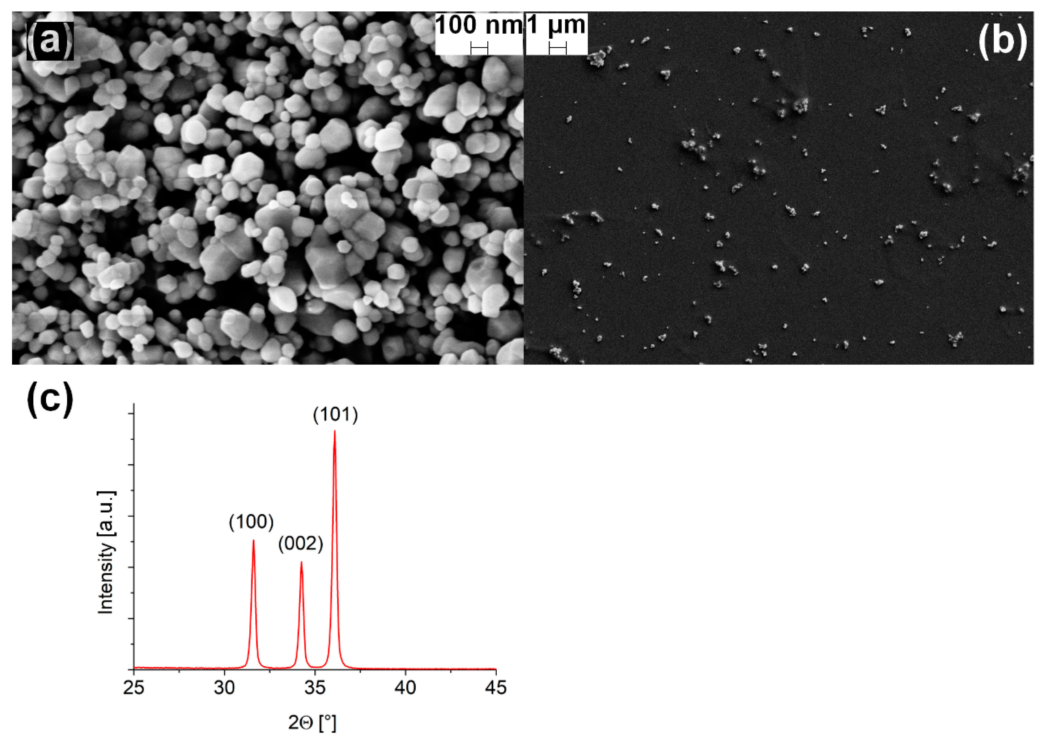
Annealed powder morphology and aggregation are investigated using SEM imaging. Figure 2a shows the top view of ZnO nanopowder at high magnification, where it can be noticed that particles with different dimensions are present, with larger crystals presenting a multifaceted structure, indicative of good crystallinity. The average particle dimension, obtained by ImageJ analysis, is 100 ± 30 nm. The XRD spectrum (Figure 2c) collected in the 25°–45° 2θ range shows the three main peaks of zinc oxide associated with the growing directions (100), (002) and (101). The spectrum reveals a high crystallinity without preferential growth, as the computation of the degree of orientation gave a value of 1.01 with respect to the reference ZnO (JCPDS #36-1451) [57]. An average crystallite dimension of 100 ± 2 nm was calculated through MAUD analysis of the XRD data.
In order to observe the natural dispersion of ZnO nanopowder sprayed from the torch nozzle, we flowed the aerosol solution through the plasma torch on a bare silicon substrate, with the plasma switched either off or on. In both cases, the same homogeneous dispersion has been obtained, and it is shown in Figure 2b. However, the amount of deposited powder is low since the area coverage fraction is estimated to be 0.38% ± 0.02%. The reason behind this low value should be searched in the high gas flow used to ignite and cool the plasma, that spreads the particles leading to the observed dispersion. Particles surface charging due to plasma interaction seems not to be an issue, since the coverage is the same with plasma switched on and off. The introduction of the aerosol in an inner coaxial channel relative to plasma may allow avoiding such repulsion among the particles.
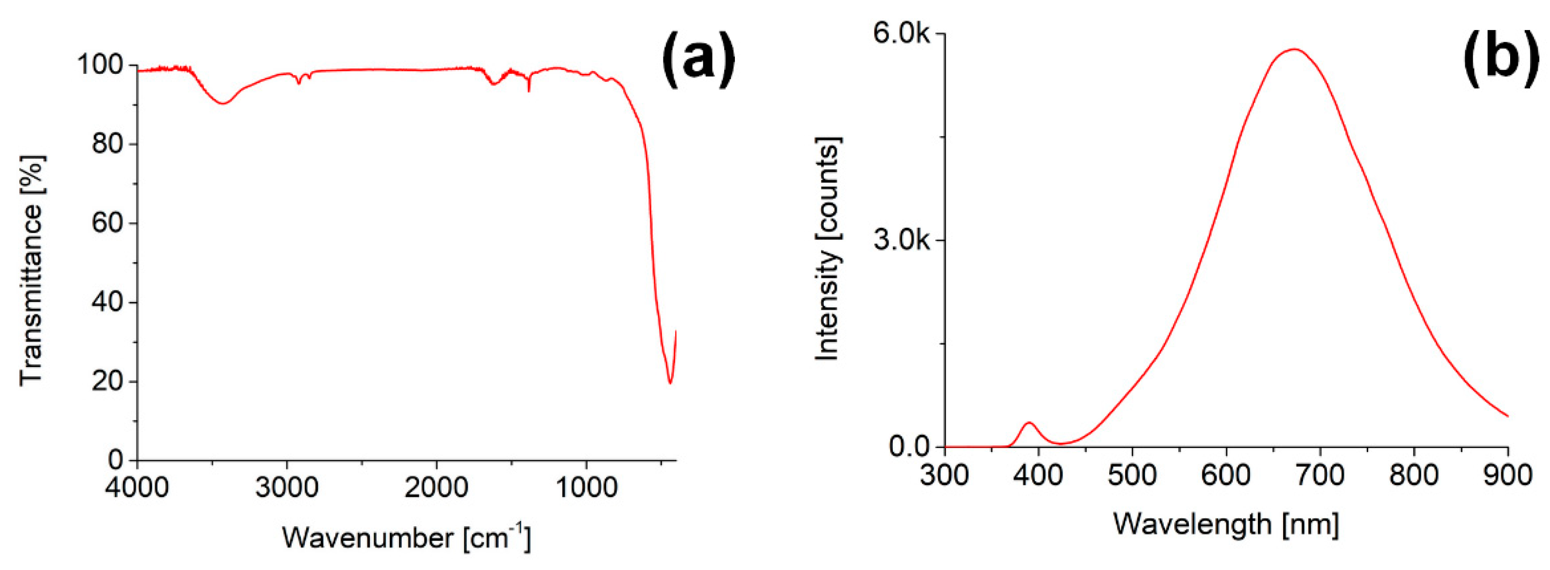
The FT-IR spectrum of zinc oxide powder after the thermal treatment (Figure 3a) shows an intense peak at 430 cm−1, which can be associated with the Zn–O stretching vibration [58], together with small bands at ν a s , C H 3 =   2960 cm−1, ν s i m , C H 2 = 2850 cm−1,   δ C H 3 = 1460 cm−1 and δ s i m , C H 3 = 1380 cm−1 ascribable to the acetate precursor residues. The wide band around 3400 cm−1 and the signal at 1615 cm−1 are due to adsorbed water.
The PL spectrum of zinc oxide under excitation with the 355 nm laser beam shows two main features (Figure 3b). The exciton emission can be observed in the small peak around 390 nm. Secondly, the broad band peaked around 675 nm can be associated with oxygen vacancies and particle surface defects [59,60] which give rise to a convolution of the orange and red emissions of zinc oxide [61].

3.2. PPH Coating

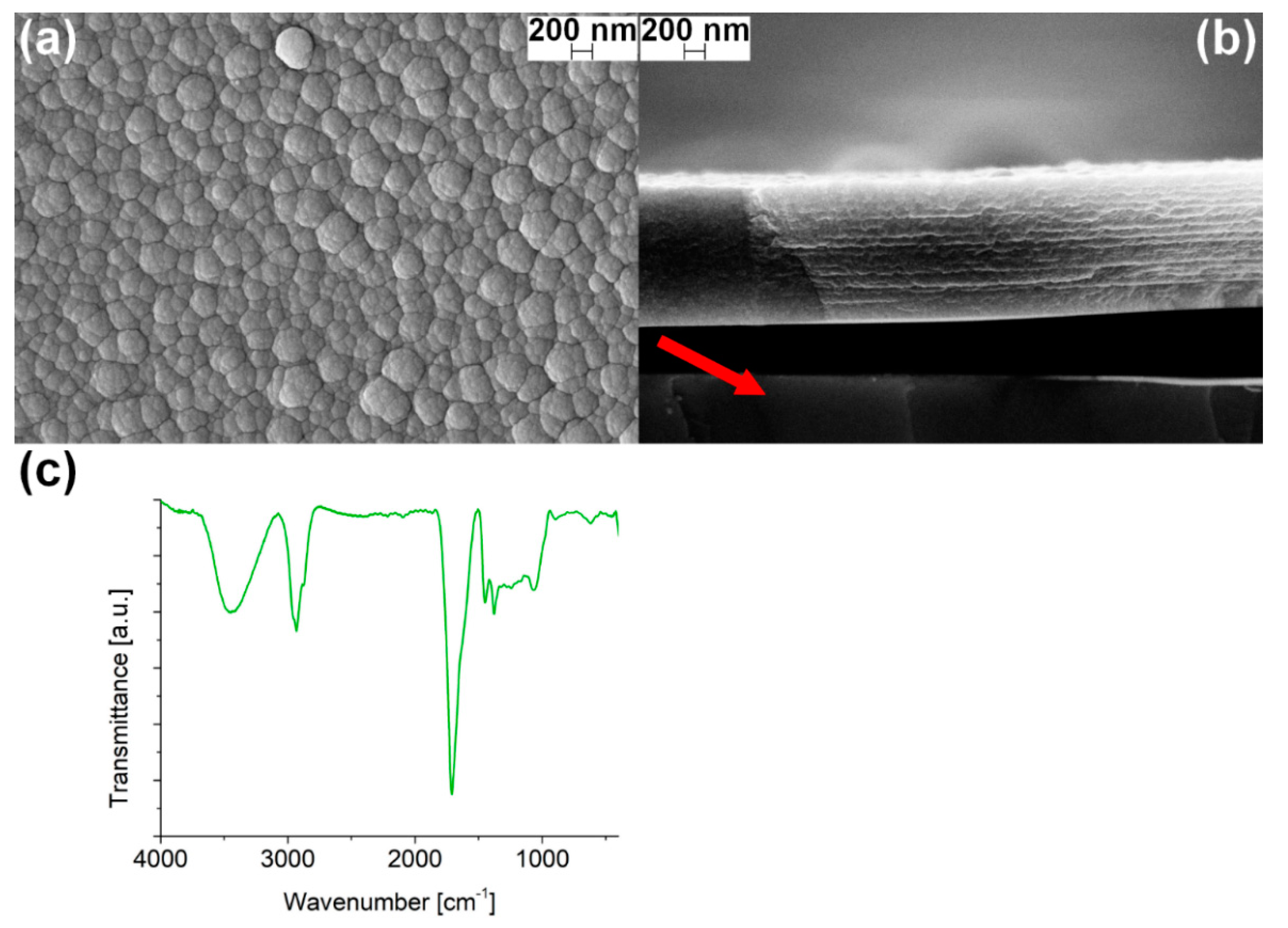
The surface of pure PPH films observed by an SEM image in top view (Figure 4a) is irregular with a cauliflower growth with a characteristic diameter of about 400 nm. However, by a deeper analysis of the SEM cross-section (Figure 4b, the film is partially detached from the substrate) the height of the roughness appears limited to few nanometers and the coating appears quite compact, indicating that the surface morphology in the top-view image is emphasized by a contrast artifact.
The cross-section image evidences a growth with a layered structure, obtained after the deposition of 20 layers. Every single layer is about 32.5 ± 5.0 nm thick, as evaluated from the image, at 300 mm/min deposition speed, meaning that the average film thickness is in the order of 600–700 nm. In addition, an average volume deposition rate can be estimated to be in the order of 10 7 cm3/s (with the active plasma diameter of about 3 mm). This value is slightly varying among the three deposition speeds tested, as reported in Table 1, because of the different plasma-substrate contact time. The average thickness of PPH samples produced at different speeds is obtained upon calibration. The deposition speed is evaluated by producing several films in the same conditions and by measuring the thickness of each film in 20 different points. Table 1 reports the mean values and dispersions of the performed measurements.
In Table 1, it is shown that the deposition rate decreases from 1.0 to 0.6 nm/s increasing the substrate speed from 300 to 500 mm/min. Then, the deposition rate remains 0.6 nm/s for a substrate speed of 800 mm/min. From 500 mm/min to 800 mm/min, the deposition rate reaches a plateau level related to the loss of precursor fragments, due to the turbulence generated in the proximity of the silicon wafer by the relative substrate speed and to the elevated gas flow (5 + 14 slm). Moreover, the residual oxygen from the atmosphere can actively oxidize a portion of the precursor producing volatile species which leads to a reduction of the overall thickness.
The PPH IR spectrum (Figure 4c) reveals the presence of the signals associated with -CH3 and -CH2 stretching vibrations ( ν a s , C H 3 =   2960 cm−1, ν a s , C H 2 = 2925 cm−1, ν s i m , C H 3 = 2870 cm−1, ν a s , C H 2 = 2850 cm−1); the bending vibrations of the same groups ( δ C H 2 = 1470 cm−1 and δ s i m , C H 3 =   1380 cm−1) are overlapped to a complex band in the range 1000–1400 cm−1; a strong peak due to the C=O stretching vibration ( ν C = O ) is present at 1715 cm−1. Even though the deposition was carried out using inert gases (Ar and N2), the appearance of carbonyl groups can be due to partial oxidation of the organic precursor in presence of residual oxygen. The signals at ν O H =   3450 cm−1 and δ O H =   1640 cm−1 are due to atmospheric moisture.
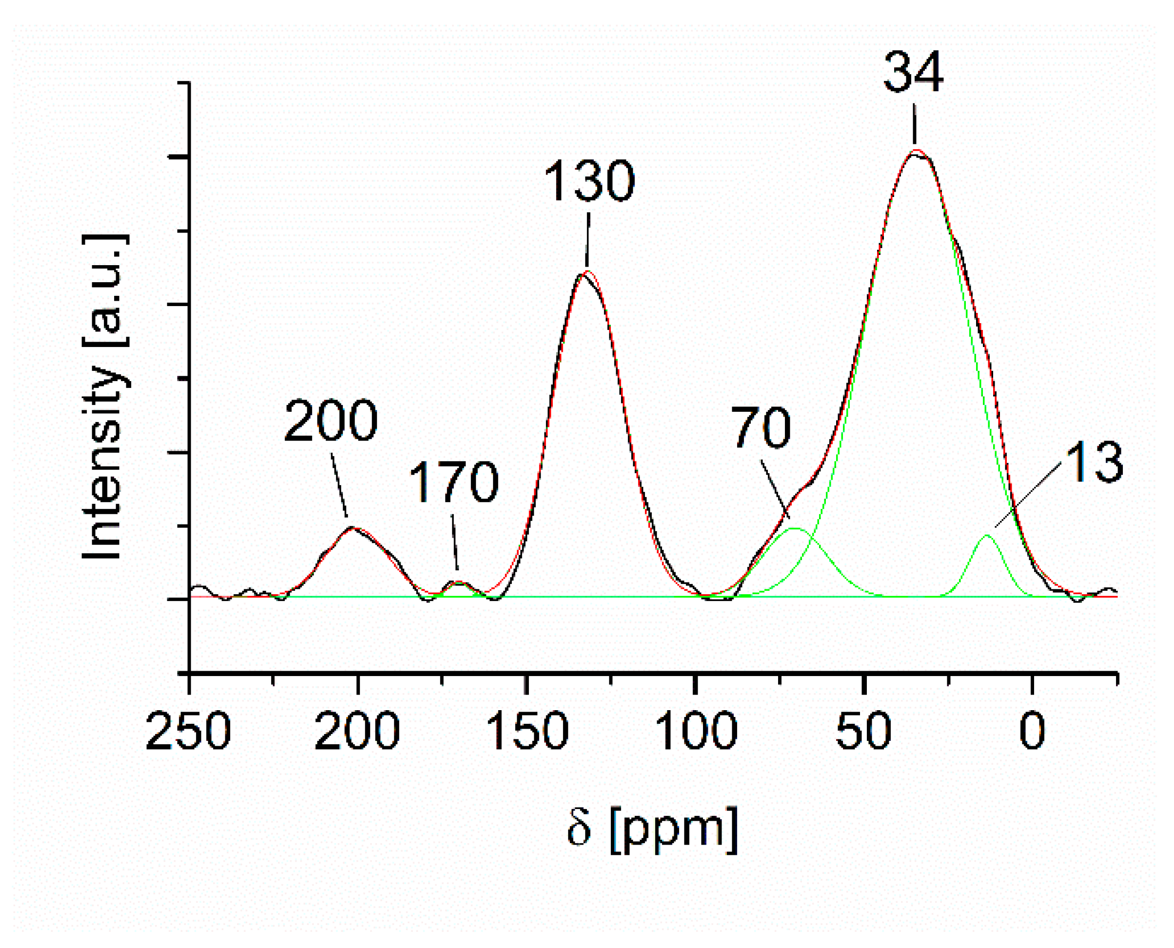
In the carbon-13 NMR spectrum from the PPH film are present several broad resonances (Figure 5), whose assignment agrees with the findings of FTIR analysis. In detail, two main resonances centered at about 130 and 33 ppm, speaking for double bonds and methylenes, respectively, are present together with minor components at about 200 and 170 ppm, attributable to ketones and other carbonyl functional groups, respectively. Moreover, the main peak centered at 30 ppm can be easily considered a convolution of at least three components lying at about 13 ppm, 34 ppm, and 70 ppm that are associated with methyls, methylenes, and ether functional groups, respectively. The acquisition parameters are selected in order to obtain the maximum intensity of all the resonances aiming to get a piece of semiquantitative information on the relative amounts of all the species. The resulting values are reported in Table 2. However, due to the broadening, other components such as methine carbons (with a typical range of 20–60 ppm) due to branching effects cannot be excluded.
In conclusion, the spectroscopic data indicate that the obtained film is a complex network composed, on average, of short aliphatic chains with a high amount of unsaturated bonds and a not negligible percentage of oxidized groups, probably due to the presence of both atmospheric oxygen surrounding the plasma and aerosol water.
This complex structure obtained after plasma polymerization depicted as a highly cross-linked network, results highly stable upon chemical exposition, as previously observed by Kondyurin et al. [62]: in particular, the PPH coatings were exposed to different chemicals in static condition by dipping the sample into the solution. Common chemical solvents were selected, such as water, ethanol, acetone, cyclohexane, and toluene, and no visible dissolution was observed after 10–15 min of exposition. In particular, the test in water showed that the adhesion force between the substrate and the film is quite weak because the film detached from the surface as a self-supporting film.
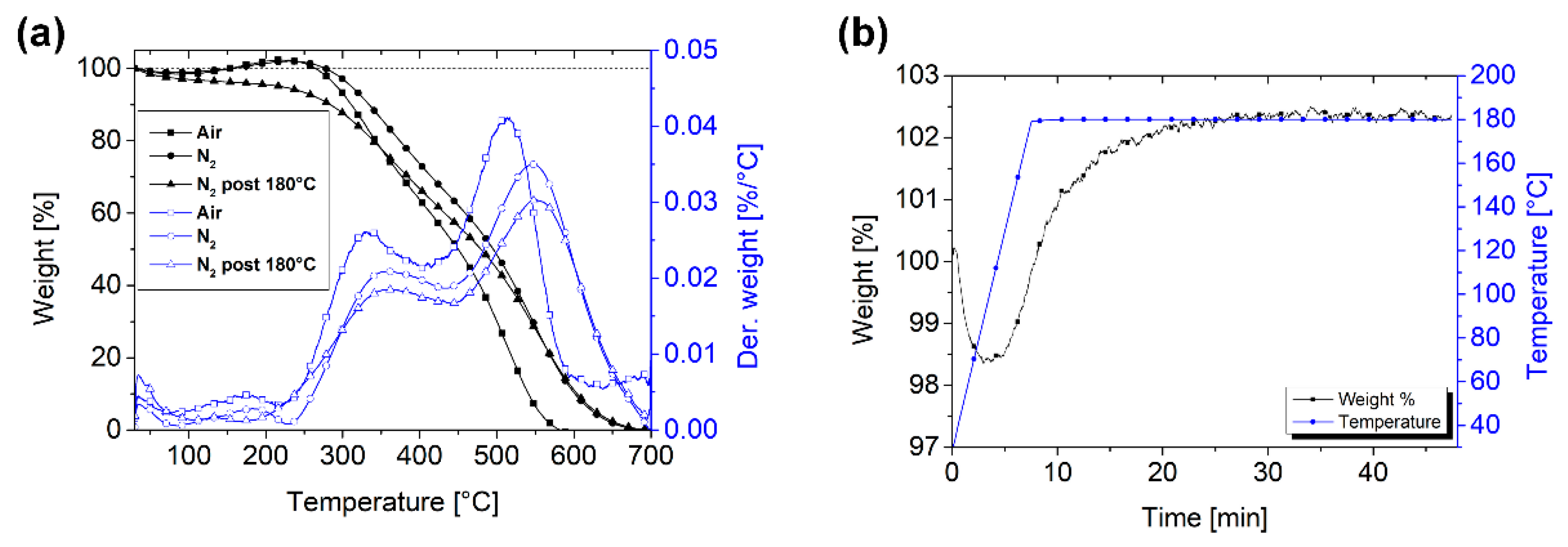
Figure 6a shows the TGA/DTG thermograms as a function of the temperature. At first, a bare sample is placed in the platinum crucible and analyzed with standard TGA parameters (N2 flow, 30–700 °C).
The initial mass loss (Figure 6a, -●-) at approx. 100 °C is associated with moisture/water evaporation, while the mass uptake of approx. 2% at 200 °C is unexpected and initially attributed to a buoyancy effect, common for low-density samples and TGA instruments with vertical setup [63]. However, a deeper investigation evidenced that the nitrogen gas employed in the test is not completely anhydrous, and therefore the mass uptake can be likely attributed to the saturation of bonds due to oxidation by moisture, as previously observed by Sundell et al. [63]. The presence of non-saturated bonds is evidenced also by NMR and FT-IR analyses, so it is likely that a temperature-activated saturation occurs.
This hypothesis is confirmed by the fact that the test performed in air (-■-) shows a similar trend in the initial portion of the curve, with mass loss at approx. 100 °C and mass uptake at approx. 200 °C. However, the thermal degradation of the sample starts at a slightly lower temperature compared to the test performed under nitrogen flow. In both cases, the curves show that the degradation starts at approx. 300 °C and occurs in two main steps, as highlighted by the trends of the mass loss derivative, which indicated that the polymeric structure is highly branched with variable lateral chain length. The looseness and the highly crosslinked and branches state of the microstructure are confirmed by the low specific gravity, measured with a helium pycnometer, which resulted in 0.248 ± 0.08 g/cm3, considerably lower than that of conventional high-molecular-weight linear polymers.
To better understand the oxidation phenomenon, a third TGA test is performed in four steps: an isothermal treatment in nitrogen at 180 °C for 40 min, followed by cooling to room temperature, permanence in air for 10 min, and a temperature ramp test in nitrogen up to 700 °C. The mass variation during the isotherm (Figure 6b) evidences a mass loss attributable to water evaporation and a subsequent mass uptake, which plateaus after 20 min. The thermogram of the subsequent TGA ramp test (-▲-) shows an initial trend with water/moisture loss but no mass uptake, which confirms that the isothermal treatment is sufficient for completing the process of saturation/oxidation of surface bonds. The fact that even a small residence time in the environment leads to a water uptake is not surprising, since the presence of hydrophilic groups has been already confirmed by FT-IR analysis.
The DTG curves (Figure 6a) indicate that the degradation at high temperature occurred in two intervals, i.e., 300–450 °C and 450–700 °C. Therefore, the first peak might be associated with side chains degradation and the second one with the degradation of the core chains, as also suggested previously [64,65]. Moreover, the peak position in the test in air (-□-) is slightly shifted to a lower temperature, indicating that the oxidation process is more effective with oxygen than with moisture. However, a deeper characterization with precise moisture fractions in the carrier gas should be performed to fully understand the phenomenon.
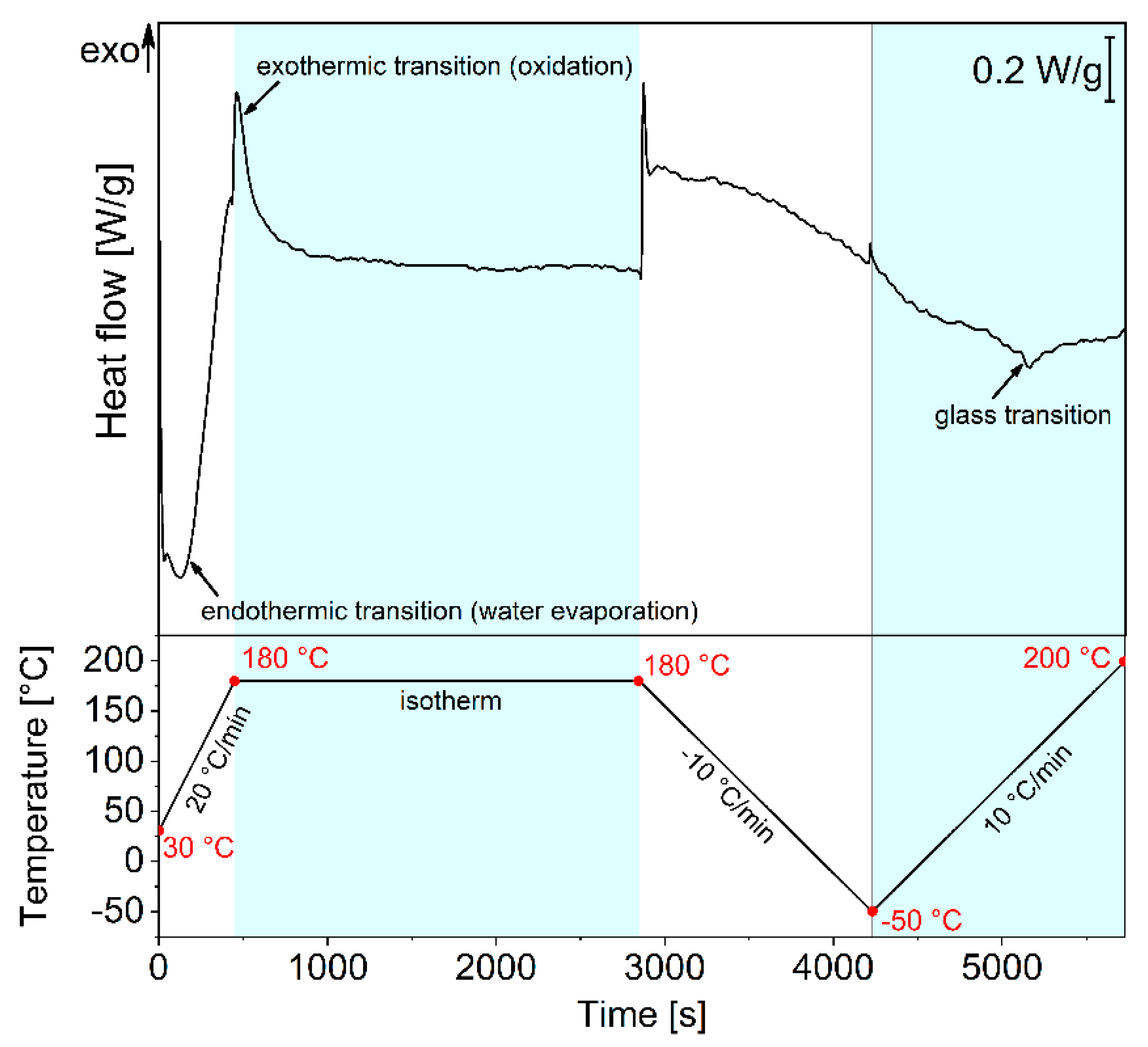
To complete the investigation of the structure and behavior of the PPH polymer, a DSC analysis with isothermal treatment is performed in nitrogen atmosphere. Figure 7 shows the combined DSC thermogram and the applied temperature profile. An initial heating ramp of 20 °C/min is applied from 30 to 180 °C, followed by an isothermal at 180 °C for 40 min, cooling at 10 °C/min down to −50 °C and heating at 10 °C/min up to 200 °C. The first heating scan evidences an endothermic signal associated with water evaporation, followed by the exothermic peak of oxidation which is completed after about 10 min of isothermal treatment. During cooling, no evident transitions can be detected, while the second heating scan shows a small endothermic signal that could be associated with a glass transition with inflection point at 99.8 °C. A second test performed in similar conditions (not shown) gave a similar endothermic signal with inflection point at 104.0 °C. These data support the hypothesis of a highly branched polymeric structure resulting from the plasma-induced polymerization of small hydrocarbon fragments, with a remarkable thermal resistance.

3.3. ZnO-PPH Films

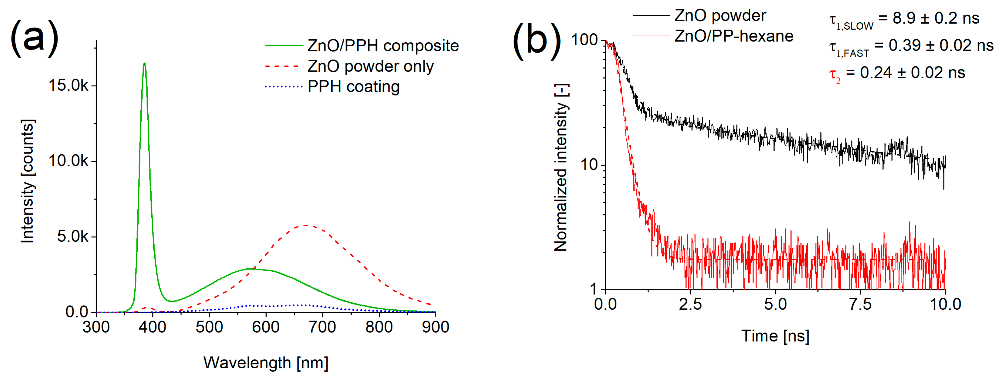
The photoluminescence spectrum of ZnO-PPH films (Figure 8a) highlights a remarkable increase in the intensity of the ZnO exciton-associated peak, while the intensity of the defective band is reduced and shifted to lower wavelengths (575 nm) compared to the powder only (dashed line) and the PPH coating only (dotted line). This considerable increase in the exciton peak is ascribed to a passivation effect of surface defects due to polymer encapsulation [62,66,67,68,69]. In fact, surface defects can trap excitonic charges, leading to a quenching of the recombination luminescence. It is worth noting that the recovering of the exciton features in ZnO particles occurs even if the embedding of the powders aggregates is not fully attained. Therefore, the interaction with polymer radicals in the plasma phase is enough to realize a surface passivation suitable for improving the oxide optical properties. The PL spectrum of the pure PPH films is characterized by two broad components in the region between 600 and 700 nm, without the presence of peaks in the near UV region typical of phenyl-containing polymers [70]. It is worth noting that its intensity is much lower than the intensity of ZnO features so that its contribution to the overall spectrum of the composite ZnO-PPH film can be neglected.
Considering the low coverage ratio of the surface, this result evidences a high increase of luminescence yield for ZnO particles covered by the polymer coating.
The position change of the visible band can be indicative of both the surface defects in the bare powder and the passivation process of the polymer coating. In fact, the high wavelength component of the broad defect band in ZnO is typically ascribed to interstitial oxygen or to OH groups [71,72]. Moreover, OH surface groups are also identified as centers contributing to the quenching of the exciton emission [73]. So, we can conclude that OH groups, which were present on the particle surface before deposition, are passivated by a thin polymer layer after the co-deposition process. The residual green band at 575 nm is the typical band related to oxygen or zinc vacancies in the particle network. To date, the proposed assignment is still controversial, and somewhere the green band has also been correlated to OH groups on the surface [44]. As evidenced by FT-IR spectra, OH groups are surely not eliminated as previously reported by Liguori et al. [48] and Fanelli et al. [46,47,74], but their reaction in the plasma phase with polymer precursors may hinder their role in trapping optically generated charges.
In Figure 8b PL decay kinetics curves of the exciton peak (395 nm) for the bare powder and for ZnO particles of co-deposited films are shown. In the powder a biexponential decay can be observed, which was fitted with the lifetimes, tf = 0.39 ± 0.02 ns and ts = 8.9 ± 0.2 ns. In ZnO-PPH films, the excitonic emission decay is more similar to a single exponential curve, characterized by a fast lifetime of about 0.24 ± 0.02 ns, whose actual evaluation is limited by the laser pulse width and the system resolution. In fact, exciton transitions in ZnO are characterized by components with time decays even lower than 100 ps; thus, for a complete analysis of the exciton transition, we should investigate the transition kinetics down to such time values. In both samples, the fast lifetime is in the order of the values observed in literature for exciton transitions quenched by defects [75,76,77]. The difference between the two samples can be ascribed to a different interaction between excitons and defects: in the bare powder the interaction occurs mainly with surface defects, while in the capped powder it occurs mainly with bulk centers. Concerning the slow component in the unembedded powder, its attribution is not fully clear for the moment, but it’s likely derived by charge release at surface trapping centers [78,79]. A component of 14 ns has been observed in ZnO single crystals [80] and was ascribed to trapping effects, giving rise to delayed recombination processes. In the present work, the disappearance of the slow component in passivated ZnO indicates that such trapping mechanisms occur at the surface defects, which are also at the origin of the exciton luminescence quenching.
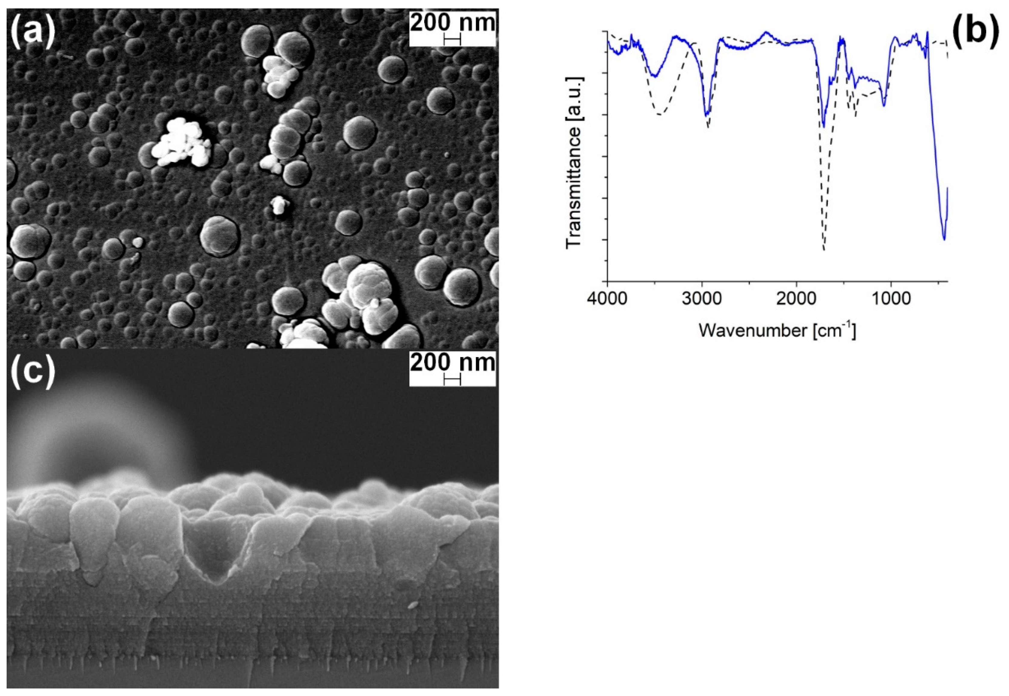
Figure 9a shows the SEM top-view, obtained with backscattered electrons detector (BSD), of a co-deposited ZnO-PPH film, produced at 300 mm/min. Here, the cauliflower morphology presents several domes with size and density compatible with the ZnO nanoparticle aggregates fully covered by the polymer coating. Few coated ZnO aggregates are visible as bright spots with a size comparable with coating thickness leading to defects in the film. Accordingly, even if the embedded ZnO particles are not clearly visible the coating morphology with ununiform cauliflower structure, with respect to the films produced with hexane only (Figure 4a), suggests their presence.
In order to indirectly verify if the morphology change could be ascribed to the presence of water as a dispersing solution for the aerosol, a dedicated test was performed. The PPH films were then deposited with pure water aerosol, therefore keeping all the parameters constant and excluding only the nanoparticles. The coating obtained showed the same structures of the PPH films (Figure 4a), therefore supporting that the dome origin is linked to the interaction between ZnO and n-hexane.
In the cross-section (Figure 9c), the layered structure due to the PPH deposition is clearly evident mixed with the growth of a columnar structure highlighted by the presence of some craters and domes higher than the coating thickness. Even if the ZnO nanoparticles are not directly detected, it is allowed to assume that the nanoparticles are the seed for the growth of the columns. In the SEM top-view image, indeed, considering the domes as enclosures of the nanoparticles in the SEM top-view image, the coverage density in ZnO-PPH films with ZnO powder can be estimated as 0.40% ± 0.02% of the surface area. This value is in good agreement with the powder-only sample. In our case, the areal density obtained is a compromise between the deposition rate of the PPH and the aerosols technology, which cannot use a more concentrated solution. Therefore, a way to improve the particle density would be the reduction of matrix deposition rate, for example using a pulsed plasma or the change of the aerosol generation technology.
FT-IR spectrum of ZnO-PPH is compared to the PPH one (dashed lines) in Figure 9b, showing good agreement along with the ZnO peak at ν Z n O = 430 cm−1 [58]. The relative intensity of the peaks is different since the thickness can vary among the samples. The OH band at ν O H = 3500 cm−1 and the signal at δ O H = 1640 cm−1 proves the presence of adsorbed water coming from the nanopowder, the solvent dispersing the nanopowder, and the polymeric film itself together with the presence of trapped OH groups in the oxide structure.

4. Conclusions

In this work, we deposited by APPJ an organic composite of ZnO nanoparticles and plasma polymerized n-hexane (PPH films) at low temperature. The ZnO nanopowder was produced by wet chemistry and characterized before being incorporated in plasma polymerized n-hexane thin films.
The PPH coating was carefully investigated in terms of structural and morphological and thermophysical properties. They resulted to be homogeneous, highly branched and with good thermal stability, even if some residual moisture was present. The deep investigation with NMR, TGA and DSC measurements gave, for the first time, important information on the structural re-arrangement of hydrocarbon chains after plasma polymerization. The branched structure allows for high thermal stability up to 300 °C, which is substantially higher compared to most of the daily-use polymers. The deposition rate of the polymeric film was studied for different substrate speeds and was in the order of 1 nm/s, reaching a plateau at high substrate speeds due to flow effects.
The co-deposited coatings resulted in polymer films covered by sub-micrometric aggregates of ZnO nanoparticles with a dome-like structure that is likely to be a consequence of the ZnO-hexane interaction. The dispersion homogeneity that can be achieved with this APPJ torch is sufficient to not influence the porosity of the coating, as highlighted by the SEM top-view images. One way to increase the concentration of deposited particles, and therefore the covered area, could be the use of a pulsed RF signal.
In addition to the interesting results on the coating stability, the coating showed relevant optical properties. The embedded ZnO, indeed, exhibited an enhanced excitonic emission and luminescence yield, with respect to the bare powder, ascribed to the passivation of surface defects by a thin polymeric capping. Surface passivation of ZnO in co-deposited films is also evidenced by the disappearance of the powder exciton slow component, ascribed to the charge release from surface trapping centers. These results open interesting possibilities to produce single- and multi-layer structures to be applied in luminescent flexible sensors for radiation monitoring.

Author Contributions

M.F., G.F., R.C., S.D. and E.C. were involved in experimental measurements and synthesis procedures, M.F., A.P. and A.Q. in scientific discussion and mentoring. All authors have read and agreed to the published version of the manuscript.

Funding

This work was supported by the Istituto Nazionale di Fisica Nucleare (INFN), 5th Committee, within the project FIRE.

Institutional Review Board Statement

Not applicable.

Informed Consent Statement

Not applicable.

Data Availability Statement

Data available on request.

Conflicts of Interest

The authors declare no conflict of interest.

References

  1. Kumar, A.; Al-Jumaili, A.; Prasad, K.; Bazaka, K.; Mulvey, P.; Warner, J.; Jacob, M.V. Pulse Plasma Deposition of Terpinen-4-ol: An Insight into Polymerization Mechanism and Enhanced Antibacterial Response of Developed Thin Films. Plasma Chem. Plasma Process. 2019, 339–355. [Google Scholar] [CrossRef]
  2. Gerchman, D.; Bones, B.; Pereira, M.B.; Takimi, A.S. Thin film deposition by plasma polymerization using D-limonene as a renewable precursor. Prog. Org. Coat. 2019, 129, 133–139. [Google Scholar] [CrossRef]
  3. Demaude, A.; Poleunis, C.; Goormaghtigh, E.; Viville, P.; Lazzaroni, R.; Delcorte, A.; Gordon, M.; Reniers, F. Atmospheric Pressure Plasma Deposition of Hydrophilic/Phobic Patterns and Thin Film Laminates on Any Surface. Langmuir 2019, 35, 9677–9683. [Google Scholar] [CrossRef] [PubMed] [Green Version]
  4. Iqbal, M.; Dinh, D.K.; Abbas, Q.; Imran, M.; Sattar, H.; Ul Ahmad, A. Controlled Surface Wettability by Plasma Polymer Surface Modification. Surfaces 2019, 2, 349–371. [Google Scholar] [CrossRef] [Green Version]
  5. Muzammil, I.; Li, Y.; Lei, M. Tunable wettability and pH-responsiveness of plasma copolymers of acrylic acid and octafluorocyclobutane. Plasma Process. Polym. 2017, 14, 1–10. [Google Scholar] [CrossRef]
  6. Patelli, A.; Mussano, F.; Brun, P.; Genova, T.; Ambrosi, E.; Michieli, N.; Mattei, G.; Scopece, P.; Moroni, L. Nanoroughness, Surface Chemistry, and Drug Delivery Control by Atmospheric Plasma Jet on Implantable Devices. ACS Appl. Mater. Interfaces 2018, 10, 39512–39523. [Google Scholar] [CrossRef] [PubMed] [Green Version]
  7. Falde, E.J.; Yohe, S.T.; Colson, Y.L.; Grinstaff, M.W. Superhydrophobic materials for biomedical applications. Biomaterials 2016, 104, 87–103. [Google Scholar] [CrossRef] [Green Version]
  8. Siow, K.S.; Kumar, S.; Griesser, H.J. Low-pressure plasma methods for generating non-reactive hydrophilic and hydrogel-like bio-interface coatings—A review. Plasma Process. Polym. 2015, 12, 8–24. [Google Scholar] [CrossRef]
  9. Hiratsuka, A.; Karube, I. Plasma polymerized films for sensor devices. Electroanalysis 2000, 12, 695–702. [Google Scholar] [CrossRef]
  10. Koparkar, K.A. Plasma polymerized thin film sensor: Synthesis and application. Sens. Transducers 2012, 143, 10–31. [Google Scholar]
  11. Lima, R.R.; Hernandez, L.F.; Carvalho, A.T.; Carvalho, R.A.M.; da Silva, M.L.P. Corrosion resistant and adsorbent plasma polymerized thin film. Sens. Actuators B Chem. 2009, 141, 349–360. [Google Scholar] [CrossRef]
  12. Thomas, D.G. The exciton spectrum of zinc oxide. J. Phys. Chem. Solids 1960, 15, 86–96. [Google Scholar] [CrossRef]
  13. Mang, A.; Reimann, K.; Rübenacke, S. Band gaps, crystal-field splitting, spin-orbit coupling, and exciton binding energies in ZnO under hydrostatic pressure. Solid State Commun. 1995, 94, 251–254. [Google Scholar] [CrossRef]
  14. Cantwell, G.; Harsch, W.C.; Jogai, B. Valence-band ordering in zno. Phys. Rev. B—Condens. Matter Mater. Phys. 1999, 60, 2340–2344. [Google Scholar] [CrossRef] [Green Version]
  15. Chen, Y.; Bagnall, D.M.; Koh, H.J.; Park, K.T.; Hiraga, K.; Zhu, Z.; Yao, T. Plasma assisted molecular beam epitaxy of ZnO on c-plane sapphire: Growth and characterization. J. Appl. Phys. 1998, 84, 3912–3918. [Google Scholar] [CrossRef]
  16. Ghamsari, M.S.; Alamdari, S.; Razzaghi, D.; Arshadi Pirlar, M. ZnO nanocrystals with narrow-band blue emission. J. Lumin. 2019, 205, 508–518. [Google Scholar] [CrossRef]
  17. Jagadish, C.; Pearton, S. Zinc Oxide Bulk, Thin Films and Nanostructures; Elsevier Science: Amsterdam, The Netherlands, 2006; ISBN 9780080447223. [Google Scholar]
  18. Wang, Z.L. Zinc oxide nanostructures: Growth, properties and applications. J. Phys. Condens. Matter 2004, 16, R829–R858. [Google Scholar] [CrossRef]
  19. Empizo, M.J.F.; Fukuda, K.; Arita, R.; Minami, Y.; Yamanoi, K.; Shimizu, T.; Sarukura, N.; Vargas, R.M.; Salvador, A.A.; Sarmago, R.V. Photoluminescence properties of a single ZnO microstructure for potential scintillator applications. Opt. Mater. (Amst). 2014, 38, 256–260. [Google Scholar] [CrossRef] [Green Version]
  20. Demidenko, V.A.; Gorokhova, E.I.; Khodyuk, I.V.; Khristich, O.A.; Mikhrin, S.B.; Rodnyi, P.A. Scintillation properties of ceramics based on zinc oxide. Radiat. Meas. 2007, 42, 549–552. [Google Scholar] [CrossRef] [Green Version]
  21. Bourret-Courchesne, E.D.; Derenzo, S.E.; Weber, M.J. Development of ZnO:Ga as an ultra-fast scintillator. Nucl. Instrum. Methods Phys. Res. Sect. A Accel. Spectrometers Detect. Assoc. Equip. 2009, 601, 358–363. [Google Scholar] [CrossRef] [Green Version]
  22. Fujimoto, Y.; Yanagida, T.; Sekiwa, H.; Yokota, Y.; Chani, V.; Yoshikawa, A. Scintillation characteristic of in,Ga-Doped ZnO thin films with different dopant concentrations. Jpn. J. Appl. Phys. 2011, 50. [Google Scholar] [CrossRef]
  23. Wen, X.; Zhang, Q.; Shao, Z. Magnetron sputtering for ZnO:Ga scintillation film production and its application research status in nuclear detection. Crystals 2019, 9, 263. [Google Scholar] [CrossRef] [Green Version]
  24. Choi, Y.-S.; Hwang, D.-K.; Oh, M.-S.; Hong, K.-P.; Em, V.T.; Choi, H.-W.; Park, S.-J. Growth and Characterization of Gallium-Doped ZnO Films for α-Particle Scintillators. J. Electrochem. Soc. 2008, 155, H909. [Google Scholar] [CrossRef]
  25. Di Mauro, A.; Fragalà, M.E.; Privitera, V.; Impellizzeri, G. ZnO for application in photocatalysis: From thin films to nanostructures. Mater. Sci. Semicond. Process. 2017, 69, 44–51. [Google Scholar] [CrossRef]
  26. Di Mauro, A.; Cantarella, M.; Nicotra, G.; Pellegrino, G.; Gulino, A.; Brundo, M.V.; Privitera, V.; Impellizzeri, G. Novel synthesis of ZnO/PMMA nanocomposites for photocatalytic applications. Sci. Rep. 2017, 7, 1–12. [Google Scholar] [CrossRef]
  27. Bharat, T.C.; Shubham; Mondal, S.; Gupta, H.S.; Singh, P.K.; Das, A.K. Synthesis of Doped Zinc Oxide Nanoparticles: A Review. Mater. Today Proc. 2019, 11, 767–775. [Google Scholar] [CrossRef]
  28. Podasca, V.E.; Buruiana, T.; Buruiana, E.C. UV-cured polymeric films containing ZnO and silver nanoparticles with UV-vis light-assisted photocatalytic activity. Appl. Surf. Sci. 2016, 377, 262–273. [Google Scholar] [CrossRef]
  29. Neal, J.S.; Devito, D.M.; Armstrong, B.L.; Hong, M.; Kesanli, B.; Yang, X.; Giles, N.C.; Howe, J.Y.; Ramey, J.O.; Wisniewski, D.J.; et al. Investigation of ZnO-based polycrystalline ceramic scintillators for use as α -particle detectors. IEEE Trans. Nucl. Sci. 2009, 56, 892–898. [Google Scholar] [CrossRef]
  30. Yanagida, T.; Fujimoto, Y.; Yoshikawa, A.; Yokota, Y.; Miyamoto, M.; Sekiwa, H.; Kobayashi, J.; Tokutake, T.; Kamada, K.; Maeo, S. Scintillation properties of in doped ZnO with different in concentrations. IEEE Trans. Nucl. Sci. 2010, 57, 1325–1328. [Google Scholar] [CrossRef]
  31. Burešová, H.; Procházková, L.; Turtos, R.M.; Jarý, V.; Mihóková, E.; Beitlerová, A.; Pjatkan, R.; Gundacker, S.; Auffray, E.; Lecoq, P.; et al. Preparation and luminescence properties of ZnO:Ga—Polystyrene composite scintillator. Opt. Express 2016, 24, 15289. [Google Scholar] [CrossRef]
  32. Rodnyi, P.A.; Chernenko, K.A.; Gorokhova, E.I.; Kozlovskii, S.S.; Khanin, V.M.; Khodyuk, I.V. Novel scintillation material ZnO transparent ceramics. IEEE Trans. Nucl. Sci. 2012, 59, 2152–2155. [Google Scholar] [CrossRef] [Green Version]
  33. Neal, J.S.; Boatner, L.A.; Giles, N.C.; Halliburton, L.E.; Derenzo, S.E.; Bourret-Courchesne, E.D. Comparative investigation of the performance of ZnO-based scintillators for use as α-particle detectors. Nucl. Instrum. Methods Phys. Res. Sect. A Accel. Spectrometers Detect. Assoc. Equip. 2006, 568, 803–809. [Google Scholar] [CrossRef]
  34. Rodnyi, P.A.; Stryganyuk, G.B.; Khodyuk, I.V. Luminescence of a ZnO:Ga crystal upon excitation in vacuum UV region. Opt. Spectrosc. 2008, 104, 210–212. [Google Scholar] [CrossRef]
  35. Katagiri, M.; Sakasai, K.; Matsubayashi, M.; Nakamura, T.; Kondo, Y.; Chujo, Y.; Nanto, H.; Kojima, T. Scintillation materials for neutron imaging detectors. Nucl. Instrum. Methods Phys. Res. Sect. A Accel. Spectrometers Detect. Assoc. Equip. 2004, 529, 274–279. [Google Scholar] [CrossRef]
  36. Gorokhova, E.I.; Anan’eva, G.V.; Demidenko, V.A.; Rodnyĭ, P.A.; Khodyuk, I.V.; Bourret-Courchesne, E.D. Optical, luminescence, and scintillation properties of ZnO and ZnO:Ga ceramics. J. Opt. Technol. 2008, 75, 741. [Google Scholar] [CrossRef] [Green Version]
  37. Simpson, P.J.; Tjossem, R.; Hunt, A.W.; Lynn, K.G.; Munné, V. Superfast timing performance from ZnO scintillators. Nucl. Instrum. Methods Phys. Res. Sect. A Accel. Spectrometers Detect. Assoc. Equip. 2003, 505, 82–84. [Google Scholar] [CrossRef]
  38. Du, X.W.; Fu, Y.S.; Sun, J.; Han, X.; Liu, J. Complete UV emission of ZnO nanoparticles in a PMMA matrix. Semicond. Sci. Technol. 2006, 21, 1202–1206. [Google Scholar] [CrossRef]
  39. Hong, R.Y.; Qian, J.Z.; Cao, J.X. Synthesis and characterization of PMMA grafted ZnO nanoparticles. Powder Technol. 2006, 163, 160–168. [Google Scholar] [CrossRef]
  40. Kulyk, B.; Kapustianyk, V.; Tsybulskyy, V.; Krupka, O.; Sahraoui, B. Optical properties of ZnO/PMMA nanocomposite films. J. Alloys Compd. 2010, 502, 24–27. [Google Scholar] [CrossRef] [Green Version]
  41. Shanshoof, H.M.; Yahaya, M.; Yunus, W.M.M.; Abdullah, I.Y. Polymer-ZnO nanocomposites foils and thin films for UV protection. AIP Conf. Proc. 2014, 1614, 136–141. [Google Scholar] [CrossRef]
  42. Tang, E.; Cheng, G.; Ma, X. Preparation of nano-ZnO/PMMA composite particles via grafting of the copolymer onto the surface of zinc oxide nanoparticles. Powder Technol. 2006, 161, 209–214. [Google Scholar] [CrossRef]
  43. Mahamumi, S.; Bendre, B.; Leppert, V.; Smith, C.; Cooke, D.; Risbud, S.; Lee, H.W. ZnO Nanoparticles Embedded in Polymeric Matrices. Nanostruct. Mater. 1996, 7, 659–666. [Google Scholar] [CrossRef]
  44. Norberg, N.S.; Gamelin, D.R. Influence of surface modification on the luminescence of colloidal ZnO nanocrystals. J. Phys. Chem. B 2005, 109, 20810–20816. [Google Scholar] [CrossRef] [PubMed]
  45. Favaro, M.; Zanazzi, E.; Patelli, A.; Carturan, S.; Ceccato, R.; Mulloni, V.; Bortolotti, M.; Quaranta, A. Aluminum doped zinc oxide coatings at low temperature by atmospheric pressure plasma jet. Thin Solid Films 2020, 708. [Google Scholar] [CrossRef]
  46. Fanelli, F.; Mastrangelo, A.M.; Fracassi, F. Aerosol-assisted atmospheric cold plasma deposition and characterization of superhydrophobic organic-inorganic nanocomposite thin films. Langmuir 2014, 30, 857–865. [Google Scholar] [CrossRef] [PubMed]
  47. Fanelli, F.; Bosso, P.; Mastrangelo, A.M.; Fracassi, F. Thin film deposition at atmospheric pressure using dielectric barrier discharges: Advances on three-dimensional porous substrates and functional coatings. Jpn. J. Appl. Phys. 2016, 55. [Google Scholar] [CrossRef]
  48. Liguori, A.; Traldi, E.; Toccaceli, E.; Laurita, R.; Pollicino, A.; Focarete, M.L.; Colombo, V.; Gherardi, M. Co-Deposition of Plasma-Polymerized Polyacrylic Acid and Silver Nanoparticles for the Production of Nanocomposite Coatings Using a Non-Equilibrium Atmospheric Pressure Plasma Jet. Plasma Process. Polym. 2016, 13, 623–632. [Google Scholar] [CrossRef]
  49. Choukourov, A.; Melnichuk, I.; Shelemin, A.; Solař, P.; Hanuš, J.; Slavínská, D.; Biederman, H. Plasma Polymerization on Mesoporous Surfaces: N-Hexane on Titanium Nanoparticles. J. Phys. Chem. C 2015, 119, 28906–28916. [Google Scholar] [CrossRef]
  50. Sohbatzadeh, F.; Shakerinasab, E.; Eshghabadi, M.; Ghasemi, M. Characterization and performance of coupled atmospheric pressure argon plasma jet with n-hexane electrospray for hydrophobic layer coatings on cotton textile. Diam. Relat. Mater. 2019, 91, 34–45. [Google Scholar] [CrossRef]
  51. Nateq, M.H.; Ceccato, R. Enhanced sol-gel route to obtain a highly transparent and conductive aluminum-doped zinc oxide thin film. Materials 2019, 12, 1744. [Google Scholar] [CrossRef] [Green Version]
  52. Yang, S.H.; Liu, C.H.; Su, C.H.; Chen, H. Atmospheric-pressure plasma deposition of SiOx films for super-hydrophobic application. Thin Solid Films 2009, 517, 5284–5287. [Google Scholar] [CrossRef]
  53. Hegemann, D.; Hanselmann, B.; Blanchard, N.; Amberg, M. Plasma-Substrate Interaction during Plasma Deposition on Polymers. Contrib. Plasma Phys. 2014, 54, 162–169. [Google Scholar] [CrossRef]
  54. Friedrich, J. Mechanisms of plasma polymerization—Reviewed from a chemical point of view. Plasma Process. Polym. 2011, 8, 783–802. [Google Scholar] [CrossRef]
  55. Lutterotti, L.; Chateigner, D.; Ferrari, S.; Ricote, J. Texture, residual stress and structural analysis of thin films using a combined X-ray analysis. Thin Solid Films 2004, 450, 34–41. [Google Scholar] [CrossRef]
  56. Bortolotti, M.; Lutterotti, L.; Pepponi, G. Combining XRD and XRF analysis in one Rietveld-like fitting. Powder Diffr. 2017, 32, S225–S230. [Google Scholar] [CrossRef]
  57. Sengupta, J.; Sahoo, R.K.; Bardhan, K.K.; Mukherjee, C.D. Influence of annealing temperature on the structural, topographical and optical properties of sol-gel derived ZnO thin films. Mater. Lett. 2011, 65, 2572–2574. [Google Scholar] [CrossRef] [Green Version]
  58. Becheri, A.; Dürr, M.; Lo Nostro, P.; Baglioni, P. Synthesis and characterization of zinc oxide nanoparticles: Application to textiles as UV-absorbers. J. Nanopart. Res. 2008, 10, 679–689. [Google Scholar] [CrossRef]
  59. Morfa, A.J.; Gibson, B.C.; Karg, M.; Karle, T.J.; Greentree, A.D.; Mulvaney, P.; Tomljenovic-Hanic, S. Single-photon emission and quantum characterization of zinc oxide defects. Nano Lett. 2012, 12, 949–954. [Google Scholar] [CrossRef]
  60. Shi, W.S.; Agyeman, O.; Xu, C.N. Enhancement of the light emissions from zinc oxide films by controlling the post-treatment ambient. J. Appl. Phys. 2002, 91, 5640–5644. [Google Scholar] [CrossRef]
  61. Kumar, V.; Swart, H.C.; Ntwaeaborwa, O.M.; Kroon, R.E.; Terblans, J.J.; Shaat, S.K.K.; Yousif, A.; Duvenhage, M.M. Origin of the red emission in zinc oxide nanophosphors. Mater. Lett. 2013, 101, 57–60. [Google Scholar] [CrossRef]
  62. Kondyurin, A.; Polonskyi, O.; Nosworthy, N.; Matousek, J.; Hlidek, P.; Biederman, H.; Bilek, M.M.M. Covalent attachment and bioactivity horseradish peroxidase on plasma-polymerized hexane coatings. Plasma Process. Polym. 2008, 5, 727–736. [Google Scholar] [CrossRef]
  63. Sundell, B.J.; Shaver, A.T.; Liu, Q.; Nebipasagil, A.; Pisipati, P.; Mecham, S.J.; Riffle, J.S.; Freeman, B.D.; McGrath, J.E. Synthesis, oxidation and crosslinking of tetramethyl bisphenol F (TMBPF)-based polymers for oxygen/nitrogen gas separations. Polymer (Guildf) 2014, 55, 5623–5634. [Google Scholar] [CrossRef]
  64. Cruz, S.M.; Viana, J.C. Melt blending and characterization of carbon nanoparticles-filled thermoplastic polyurethane elastomers. J. Elastomers Plast. 2015, 47, 647–665. [Google Scholar] [CrossRef] [Green Version]
  65. Han, B.; Cheng, A.; Ji, G.; Wu, S.S.; Shen, J. Effect of organophilic montmorillonite on polyurethane/montmorillonite nanocomposites. J. Appl. Polym. Sci. 2004, 91, 2536–2542. [Google Scholar] [CrossRef]
  66. Guo, L.; Yang, S.; Yang, C.; Yu, P.; Wang, J.; Ge, W.; Wong, G.K.L. Highly monodisperse polymer-capped ZnO nanoparticles: Preparation and optical properties. Appl. Phys. Lett. 2000, 76, 2901–2903. [Google Scholar] [CrossRef]
  67. Jetson, R.; Yin, K.; Donovan, K.; Zhu, Z. Effects of surface modification on the fluorescence properties of conjugated polymer/ZnO nanocomposites. Mater. Chem. Phys. 2010, 124, 417–421. [Google Scholar] [CrossRef]
  68. Chen, C.; He, H.; Lu, Y.; Wu, K.; Ye, Z. Surface passivation effect on the photoluminescence of ZnO nanorods. ACS Appl. Mater. Interfaces 2013, 5, 6354–6359. [Google Scholar] [CrossRef]
  69. Clementi, C.; Rosi, F.; Romani, A.; Vivani, R.; Brunetti, B.G.; Miliani, C. Photoluminescence properties of zinc oxide in paints: A study of the effect of self-absorption and passivation. Appl. Spectrosc. 2012, 66, 1233–1241. [Google Scholar] [CrossRef]
  70. Zanazzi, E.; Favaro, M.; Ficorella, A.; Pancheri, L.; Dalla Betta, G.F.; Quaranta, A. Real-Time Optical Response of Polysiloxane/Quantum Dot Nanocomposites under 2 MeV Proton Irradiation: Luminescence Enhancement of Polysiloxane Emission through Quantum Dot Sensitization. Phys. Status Solidi Appl. Mater. Sci. 2020, 217. [Google Scholar] [CrossRef]
  71. Djurišić, A.B.; Leung, Y.H.; Tam, K.H.; Hsu, Y.F.; Ding, L.; Ge, W.K.; Zhong, Y.C.; Wong, K.S.; Chan, W.K.; Tam, H.L.; et al. Defect emissions in ZnO nanostructures. Nanotechnology 2007, 18. [Google Scholar] [CrossRef]
  72. Djurišić, A.B.; Leung, Y.H. Optical properties of ZnO nanostructures. Small 2006, 2, 944–961. [Google Scholar] [CrossRef] [PubMed]
  73. Zhou, H.; Alves, H.; Hofmann, D.M.; Kriegseis, W.; Meyer, B.K.; Kaczmarczyk, G.; Hoffmann, A. Behind the weak excitonic emission of ZnO quantum dots: ZnO/Zn(OH) 2 core-shell structure. Appl. Phys. Lett. 2002, 80, 210–212. [Google Scholar] [CrossRef]
  74. Fanelli, F.; Mastrangelo, A.M.; De Vietro, N.; Fracassi, F. Preparation of multifunctional superhydrophobic nanocomposite coatings by aerosol-assisted atmospheric cold plasma deposition. Nanosci. Nanotechnol. Lett. 2015, 7, 84–88. [Google Scholar] [CrossRef]
  75. Chichibu, S.F.; Onuma, T.; Kubota, M.; Uedono, A.; Sota, T.; Tsukazaki, A.; Ohtomo, A.; Kawasaki, M. Improvements in quantum efficiency of excitonic emissions in ZnO epilayers by the elimination of point defects. J. Appl. Phys. 2006, 99. [Google Scholar] [CrossRef]
  76. Camarda, P.; Messina, F.; Vaccaro, L.; Agnello, S.; Buscarino, G.; Schneider, R.; Popescu, R.; Gerthsen, D.; Lorenzi, R.; Gelardi, F.M.; et al. Luminescence mechanisms of defective ZnO nanoparticles. Phys. Chem. Chem. Phys. 2016, 18, 16237–16244. [Google Scholar] [CrossRef] [PubMed]
  77. Wilkinson, J.; Ucer, K.B.; Williams, R.T. Picosecond excitonic luminescence in ZnO and other wide-gap semiconductors. Radiat. Meas. 2004, 38, 501–505. [Google Scholar] [CrossRef]
  78. Voss, T.; Wischmeier, L. Recombination dynamics of surface-related excitonic states in single ZnO nanowires. J. Nanosci. Nanotechnol. 2008, 8, 228–232. [Google Scholar] [CrossRef] [PubMed]
  79. Furukawa, Y.; Tanaka, M.; Nakazato, T.; Tatsumi, T.; Nishikino, M.; Yamatani, H.; Nagashima, K.; Kimura, T.; Murakami, H.; Saito, S.; et al. Temperature dependence of scintillation properties for a hydrothermal-method-grown zinc oxide crystal evaluated by nickel-like silver laser pulses. J. Opt. Soc. Am. B 2008, 25, B118. [Google Scholar] [CrossRef]
  80. Koida, T.; Chichibu, S.F.; Uedono, A.; Tsukazaki, A.; Kawasakib, M.; Sota, T.; Segawa, Y.; Koinuma, H. Correlation between the photoluminescence lifetime and defect density in bulk and epitaxial ZnO. Appl. Phys. Lett. 2003, 82, 532–534. [Google Scholar] [CrossRef]
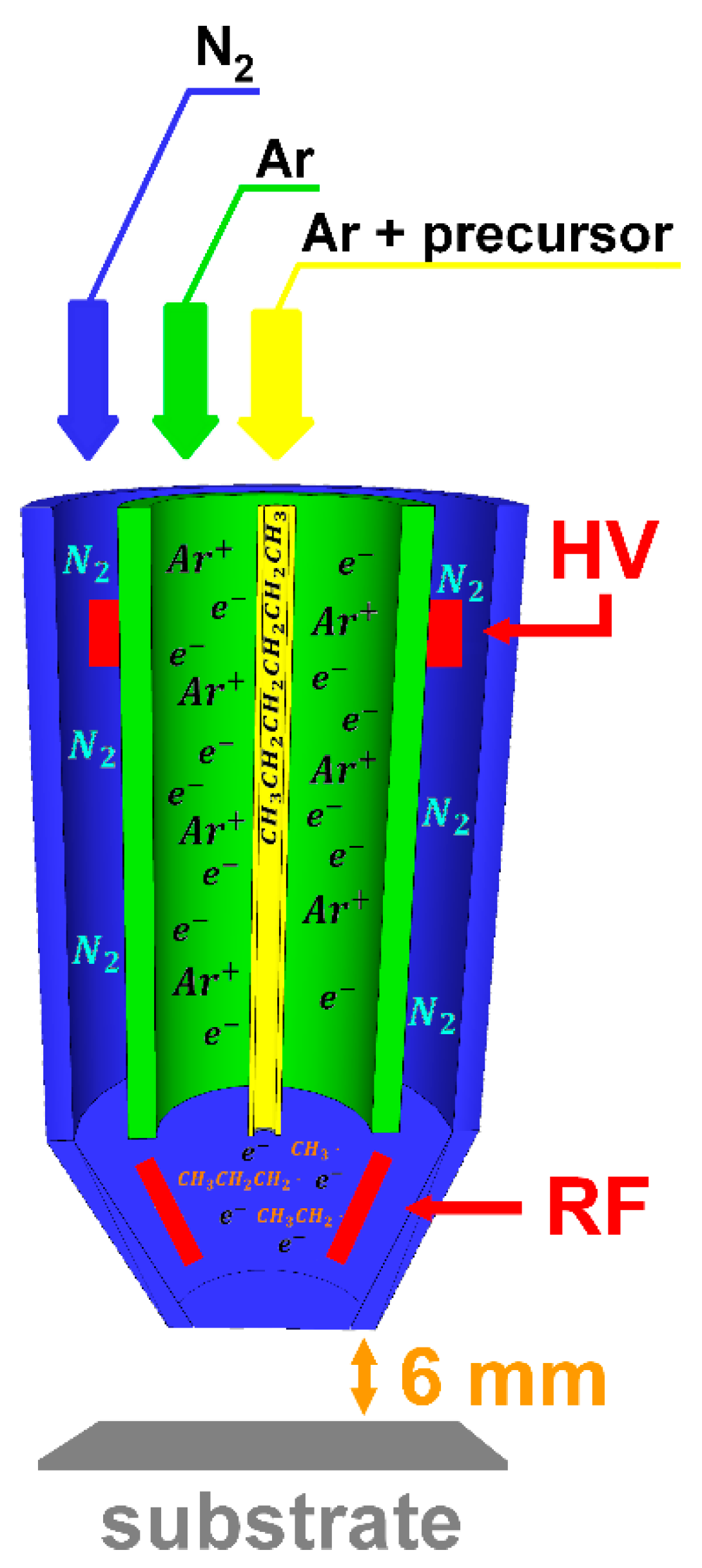
Figure 1. Plasma torch scheme and reactions.
Coatings 11 00167 g001
Figure 2. (a) High magnification SEM top-view of the synthesized ZnO powder; (b) surface dispersion of ZnO on an uncoated substrate; (c) XRD spectrum of the ZnO powder annealed at 600 °C.
Coatings 11 00167 g002
Figure 3. (a) FT-IR spectrum and (b) PL spectrum (λex = 355 nm) of the bare ZnO powder.
Coatings 11 00167 g003
Figure 4. (a) SEM top-view and (b) SEM cross-section of a pure PPH coating deposited at 300 mm/min (red arrow indicates the silicon substrate); (c) FT-IR spectrum of the PPH film.
Coatings 11 00167 g004
Figure 5. 13C-NMR spectrum of pure PPH coating.
Coatings 11 00167 g005
Figure 6. (a) TGA/DTG curves for the samples treated in N2 and air; (b) isothermal treatment profile.
Coatings 11 00167 g006
Figure 7. DSC thermogram with combined temperature profile applied to the sample.
Coatings 11 00167 g007
Figure 8. (a) PL spectrum (λex = 355 nm) of the ZnO-PPH coating compared with the ZnO powder only (red dashed line) and pure PPH coating (blue dotted line); (b) PL time-resolved curves of the ZnO exciton feature at 395 nm (λex = 375 nm) for the bare ZnO powder and for the ZnO-PPH films.
Coatings 11 00167 g008
Figure 9. (a) SEM top-view with BSD detector of a ZnO-PPH coating (bright spots indicate ZnO clusters); (b) FT-IR spectrum of ZnO-PPH film (blue), the pure PPH FTIR spectrum (black dashed line) is also reported for comparison; (c) SEM cross-section of the ZnO-PPH film showing the layered structure and aggregates.
Coatings 11 00167 g009
Table 1. Average thickness and deposition rate of the PPH film as a function of deposition speed for a total number of 20 scans.
Deposition Speed [mm/min]Film Thickness [nm]Deposition Time [s]Average Deposition Rate [nm/s]
300650 ± 106401.02 ± 0.02
500230 ± 103800.61 ± 0.03
800150 ± 102400.62 ± 0.04
Table 2. Chemical shift, amount ad assignment of main signals in the 13C CPMAS spectrum of PPH film [53].
δ [ppm]Relative Amount [%]Assignment
2005C=O
170<1O–C=O
13030=CH
703C–O–C
3457>CH2
136–CH3
Publisher’s Note: MDPI stays neutral with regard to jurisdictional claims in published maps and institutional affiliations.