Article

Improvement in the Figure of Merit of ITO-Metal-ITO Sandwiched Films on Poly Substrate by High-Power Impulse Magnetron Sputtering

1
Center for Advanced Thin Films and Devices, School of Materials and Energy, Southwest University, Chongqing 400715, China
2
Design and Materials for Medical Equipment and Devices, Department of Materials Science and Engineering, Da-Yeh University, Changhua 51591, Taiwan
3
Department of Materials Science and Engineering, National Chung Hsing University, Taichung 40227, Taiwan
4
Institute of Chemistry, Academia Sinica, Taipei 11529, Taiwan
*
Authors to whom correspondence should be addressed.
Coatings 2021, 11(2), 144; https://doi.org/10.3390/coatings11020144
Submission received: 8 January 2021 / Revised: 22 January 2021 / Accepted: 25 January 2021 / Published: 28 January 2021

Abstract

:
High-power impulse magnetron sputtering (HiPIMS) was used to deposit ITO/Ag/ITO (IAgI) and ITO/Cu/ITO (ICuI) sandwiched films on polyethylene naphthalate substrate at room temperature as flexible transparent conductive materials. The hybrid layers were constructed with 40 nm ITO bottom and top layers, and a 5–20 nm Ag or Cu interlayer. The microstructure and optoelectrical properties were estimated for these films with various thicknesses of the metal interlayer. Thanks to the high-power density and highly ionized plasma in the HiPIMS process, the IAgI and ICuI sandwich structures exhibited good crystallinity and smooth surfaces with high optical transmittance and low sheet resistance. The optimal figure of merit was obtained as 101.16 × 10⁻³·Ω−1 for the IAgI film and 4.83 × 10⁻³·Ω−1 for the ICuI film with the metal interlayer thickness of 10 nm, both of which are higher than that from a similar structure reported via sputtering at room temperature. These results indicate that HiPIMS is a promising technique to deposit transparent conductive films onto soft substrates for applications in flexible optoelectronic devices.

Graphical Abstract

1. Introduction

The development of flexible optoelectronic devices, such as photovoltaic solar cells, thin-film transistors, touch screen panels and organic light-emitting diodes, demands high quality transparent conductive oxides (TCO) available on large scale polymer substrates [1,2,3,4,5,6,7,8,9]. Indium-tin oxide (ITO) is the most widely used TCO material with high optical transmittance and good conductivity [10,11,12,13,14,15]. However, a single ITO layer is not adequately stable for use on flexible substrates. A single ITO layer also cannot achieve the stringent requirements when the diagonal size of the screen increases [16]. A multiple-layer structure embedding a thin metal layer within two TCO layers has been proposed [17,18,19,20,21,22,23,24]. Specifically, the insertion of a thin Ag or ultra-thin Cu (below 30 nm thickness) interlayer led to improved electrical and optical properties [25,26,27,28,29]. The deposition of high-quality multilayer films on polymer substrates is difficult due to restrictions of the substrate temperature during the deposition process. Mostly, RF/DC magnetron sputtering was applied to deposit TCO films on polymer substrates at room temperature with low power density. Drawbacks of high resistivity, lower transmittance and the brittleness of the films resulted from the amorphous nature of the sputtered films [30,31,32]. Low-temperature annealing [33], refractive index-matching layers [34,35] and buffer layers [36] have been adopted to improve the performance of the TCO films deposited on polymer substrates, which inevitably complicates the manufacturing process and increases cost. High power density magnetron sputtering improves the crystallinity but comes with nonuniform grain size [37]. As such, currently, all magnetron sputtered TCO films are deposited at a low power density of a few W/cm2 [38,39], giving rise to low crystallinity and thus low conductivity.
The high-power impulse magnetron sputtering (HiPIMS) technique has been employed to deposit films on polymer substrates [40,41,42]. It provides high peak power density (>0.5 kW/cm2) and current density (3–4 A/cm2), low duty cycle (less than 5%) and about three orders of magnitude higher plasma density (1018–1019 m−3) than that of the conventional magnetron sputtering [43,44]. The high ionization of the target atoms and the working gas enable better control of the film growth, leading to a high-quality film with good uniformity, better adhesion, low defectivity and less roughness at a relatively low substrate temperature [40,45,46,47]. Furthermore, the use of HiPIMS to deposit ITO and Cu can improve the qualities thus the properties of the film [37,48]. However, there is a lack of TCO/metal/TCO films deposited by HiPIMS. In our group, HiPIMS has been successfully used to deposit many kinds of films and coatings [49,50,51].
In this study, HiPIMS was used to deposit ITO-Ag-ITO (IAgI) and ITO-Cu-ITO (ICuI) sandwich structures on 125 μm thick polyethylene naphthalate (PEN) substrate. The bottom and top ITO layers were fixed at 40 nm, and the thickness of the Ag and Cu interlayer was varied from 5 to 20 nm. The microstructures and optoelectrical properties of IAgI and ICuI films with various thicknesses of the interlayer were investigated. The metal-inserted sandwich structures with large figures of merit (ΦTC) were obtained on flexible TCO films with higher transmittance and lower sheet resistance.

2. Materials and Methods

In this research, thin metal films of Ag or Cu were inserted in between two ITO thin films to form two different ITO–metal–ITO (IMI) sandwich structured films, ITO/Ag/ITO and ITO/Cu/ITO. These two sandwich films were prepared using HiPIMS technique (Huettinger Highpulse 4001 G2) on flexible substrates (PEN) and Si substrate. Si substrate was used for selected film characterizations. The thickness of the polymer substrates was 125 μm. During the deposition, the substrate rotated at a speed of 5 rpm at room temperature without bias. A thermal couple near the substrate surface was used to measure the substrate temperature. ITO (99.99%, Sn2O3:In2O3 = 90:10 wt.%) and metal target (Ag: 99.95%, Cu: 99.99%) were used to deposit the ITO films and metal films with a unipolar mode and arc handling capability of 1000 arcs/s. The magnetic track area inside the cathode was 126 cm2. After the system was evacuated to 1 × 10⁻⁶ torr, the deposition process was performed at 3 × 10⁻³ torr with pure Ar flow at a rate of 30 sccm.
Before the deposition process, all the targets were cleaned for 5 min with peak current of 6 A, duty cycle of 30%, frequency of 1000 Hz and pulse-on time of 300 μs. During the HiPIMS process, the real-time voltage and current were obtained using a digital oscilloscope. The triple-layer structure films were obtained by depositing ITO and thin metal layers sequentially in the HiPIMS system, in which every combination of each thickness was adopted to determine the optimum condition; 150 Hz frequency, 100 μs pulse-on time and 1.0 kW average power were employed for the ITO deposition. The frequency for the metal interlayer deposition was 250 Hz. The pulse-on times were 150 and 100 μs for Cu and Ag targets, respectively. A constant current mode was used while the peak current setting for the Ag target was 50 A and that for the Cu target was 100 A. According to the recordings from the digital oscilloscope, the mean power (voltage × current × duty cycle) value of the Ag targets was around 1.3 kW, and that of the Cu targets was around 2.1 kW; the peak power (the highest voltage × highest current during the pulse) value was 48.6 kW for the Ag target and 61.9 kW for the Cu target. During the whole deposition process, the system temperature was below 70 °C.
An α-step profile analyzer (Tencor P-10, Surface profiler, Class One Equipment Inc., Decatur, GA, USA) was used to measure the film thickness. The microstructures of the films were determined using grazing incident X-ray diffraction (GIXRD, BRUKER D8 and BRUKER D8 SSS, PANanalytical, Almelo, Netherlands) with a 1.5-degree incident angle, and the root-mean-square (RMS) surface roughness was measured by atomic force microscopy (AFM, Agilent 5400, Agilent Technologies, Santa Clara, CA, USA). A JSM-6700F field-emission scanning electron microscope (FE-SEM, JEOL, Tokyo, Japan) was used at an operating voltage of 3.0 kV to analyze the surface morphology of the Ag or Cu layers on the bottom ITO film. The film composition and the chemical bonding state were characterized by X-ray photoelectron spectroscopy (XPS, ULVACPHI, PHI 5000 VersaProbe, ULVACPHI, Chigasaki, Japan) with a primary excitation source of monochromatized Al-Kα (1486.6 eV); the pass energy was fixed at 50 eV and the beam current density was 2.5 × 10⁻³ A/cm2. The optical transmittances of the ITO/Ag/ITO and ITO/Cu/ITO triple-layer structures were measured by an N & K analyzer (model: 1280, N & K Technol, San Jose, CA, USA). Van der Pauw Hall measurements (ACCENT, HL-5500PC, Nanometrics, Milpitas, CA, USA) were used to measure the electrical properties of the films.

3. Results and Discussion

3.1. Material Properties of the Sandwiched TCO Films

A TCO film’s crystallinity determines its photoelectric property. Figure 1 shows GIXRD patterns of the IAgI (a) and ICuI (b) hybrid layers of various thicknesses deposited on the PEN substrate. It shows that all the films had crystalline structures. Except for the peaks responding to the PEN substrate, the diffraction peaks (222) and (400) associated with the ITO layer were observed for all the samples, indicating the crystallinity of the ITO film with body-centered structure (JCPDS card number 06-0416). The IAgI films possessed an Ag (111) peak around 38.2°, corresponding to the FCC crystalline structure. For the ICuI films, a broad Cu (200) peak at 50.8° was observed for the films. There is no obvious difference in the peak intensity according to the various metal interlayer thickness, indicating stable film quality deposited by HiPIMS even with the 5 nm ultra-thin metal interlayer. The crystalline size of the metal interlayer was obtained from the Scherer equation.
D = 0.9λ/βcosθ
where λ = 0.154 nm is the wavelength of the X-ray radiation, β is the corrected full width at half-maximum (FWHM) and θ is the Bragg angle. The calculated results of the Ag (111) and Cu (200) crystalline sizes are presented in Table 1. With the increase of the metal interlayer thickness from 5 to 20 nm, the Ag and Cu grain size show varying degrees of increase. The grain size of the Ag layer was fairly large due to the agglomeration of the Ag atoms, whereas the Cu layer inserted in the ICuI films had very fine grain. Here, it is also worth mentioning the grain size effect for both the electrical and optical properties of the films: higher values of grain size imply reduced scattering at grain borders, and consequently, increased electrical conductivity of the film and higher light transparency. Hence, a better performance of IAgI films is expected with the larger grain size.
It should be noted that, in other studies of IAgI or ICuI films deposited by magnetron sputtering on polymer or glass substrates at room temperature, they rarely showed any strong diffraction peaks in the XRD patterns [29,52,53]. That was mainly due to the low substrate temperature, the low kinetic energy of the sputtered atoms and too-thin a metal interlayer in IMI films to form the crystalline phase. The poor crystalline film could be highly defective with more grains at the boundaries, resulting in a serious hindrance to carrier transport, thereby leading to a higher film resistivity. In this study, the HiPIMS process provided high plasma density and more activated ions to make it more effective in the crystallization of ITO and metal films. This superiority of HiPIMS is more obvious when depositing ultra-thin films, as in the samples in this study.
FESEM views of 5 and 10 nm Ag and Cu films on the bottom ITO deposited on the PEN substrate are shown in Figure 2, respectively. In the case of 5 nm Ag thickness, Ag islands were observed (Figure 2a). These Ag islands scattered the incident light, most likely leading to a low transmittance. Additionally, the discontinuous Ag film could hardly contribute to the conductivity of the sandwiched IAgI film. When the Ag thickness increased to 10 nm, a continuous Ag film formed and almost completely covered the bottom ITO layer, as shown in Figure 2b. The coalesced Ag islands could suppress the light reflections and scatterings and remarkably decrease the sheet resistance, resulting in high conductivity and transmittance of the films. For the Cu film grown on the bottom ITO layer, the continuous film with very small Cu particles formed with 5 nm Cu film thickness, as shown in Figure 2c. With the increase of the Cu layer thickness to 10 nm, there is no obvious difference in the surface morphology, except flatter and smoother, as seen in Figure 2d, due to the longer deposition time.
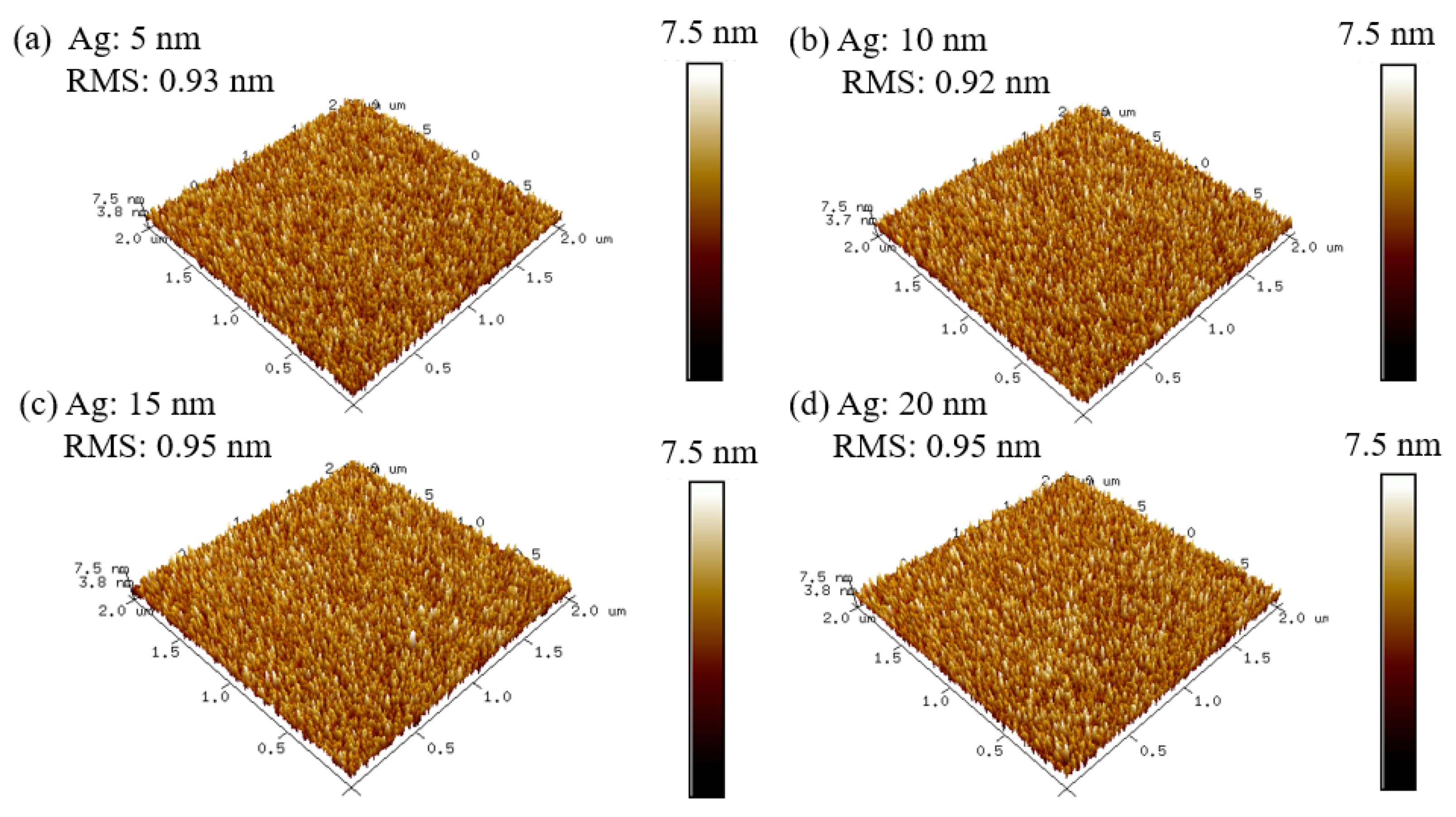
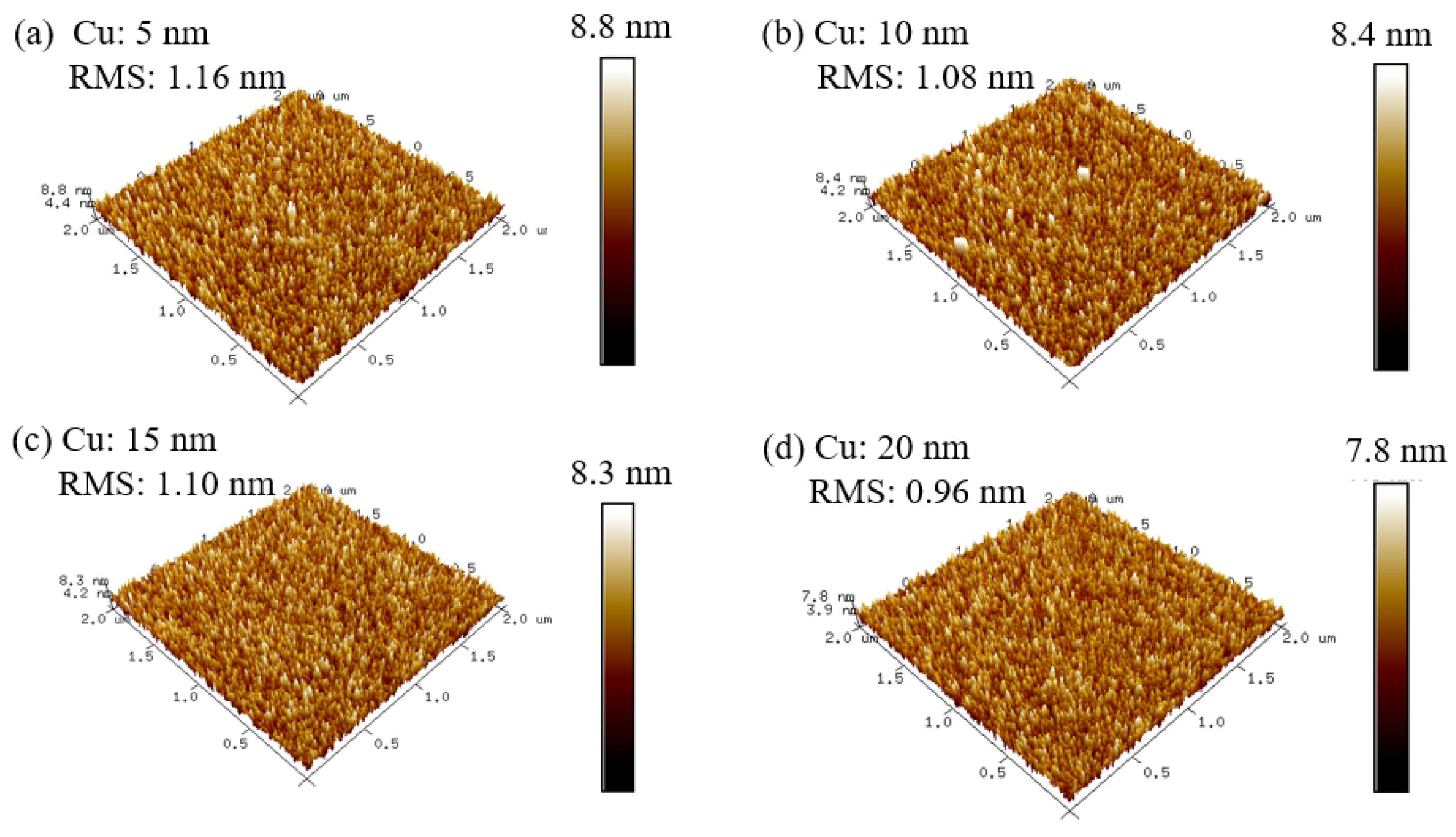
The surface roughness of a TCO film is important, as it affects the electro-optical properties of the films. The atomic force microscopy (AFM) images in Figure 3 and Figure 4 show the surface roughness of IAgI and ICuI films deposited on the glass substrate, respectively. The RMS values of the IAgI films were determined to be 0.93, 0.92, 0.95 and 0.95 nm, and those of the ICuI films were 1.16, 1.08, 1.10 and 0.96 nm with the interlayer thicknesses of 5, 10, 15 and 20 nm, respectively. These films exhibited very smooth surfaces regardless of the metal layer thickness, which is attributed to the advantages of the HiPIMS process, mainly including average powder size and denser coating morphology. A smooth surface improves the transmittance by reducing the diffused reflection of light, and also suppresses the scattering of free carriers, leading to an increase in carrier mobility and thus a decrease in electrical resistivity. These effects are notable, particularly in very thin films, like the films in this study. The smooth surface can also be expected to form a continuous metal interlayer in this sandwich structure.
Following a peak fitting procedure, Ag 3d and Cu 2p XPS spectra of IAgI and ICuI films on PEN substrate with an Ag/Cu thickness of 10 nm were gathered (Figure 5). Two spin–orbit pairs of components are individuated in Figure 5a. The main Ag 3d5/2 component is centered at binding energy (BE) 368.4 eV, corresponding to metallic silver atoms [54,55]. The second spin–orbit pair of low intensity at a higher BE value (Ag 3d5/2 at 368.4 eV) results from the oxidized Ag [56]. The Cu 2p spectrum (Figure 5b) identified two spin–orbit pairs as well. The pure Cu 2p core reached 932.0 eV (Cu2p3/2) and 951.8 eV (Cu2p1/2). The peak at 932 eV could also indicate the possibility of the presence of CuO (Cu2O). As the peak area is proportional to the intensity of the associated component, the intensity ratios of metallic atoms to oxidized parts were determined as 0.90:0.10 for IAgI films and 0.91:0.09 for ICuI films. The XPS spectra indicate that independent Ag and Cu interlayers were deposited with small extents of oxidation.

3.2. Opto-Electrical Properties of the Sandwiched TCO Films

Figure 6 displays the transmittance spectra of IAgI and ICuI sandwich films with the various thicknesses of the interlayer of Ag and Cu on the PEN substrate. The 80 nm ITO films without the metal interlayer show an optical transmittance of 72.32% at a wavelength of 550 nm. The transmittance of the IAgI and ICuI films varies with the thicknesses of the Ag and Cu layers. For the IAgI films in Figure 6a, with the Ag thickness of 5 nm, the transmittance of 83.25% was observed at a wavelength of 550 nm. The increase of the Ag thickness to 10 nm led to a transmittance improvement to 96.61% due to the transformation of the morphology of the Ag film from discontinuous to continuous, as shown in Figure 2, which has lower adsorption. With further increases of the Ag thickness to 15 and 20 nm, the transmittance decreased gradually. For the ICuI sandwich films, a monotonic slight decrease of the optical transmittance in the visible region was observed with the increase of the thickness of the Cu interlayer from 5 to 20 nm, as displayed in Figure 6b. The highest transmittance of 80.16% was observed at a Cu thickness of 5 nm. The decrease of the optical transmittance of the IMI films with the increase of the metal interlayer thickness was due to the increase of the free carrier concentration (absorption) and the reflection from the thicker metal layer. The higher optical transmittance of IAgI than ICuI sandwich film in the 400–800 nm wavelength range can be attributed to the more effective surface plasmon resonance of the Ag layer than that of the Cu layer [57,58]. Figure 6 also shows that the 80 nm ITO films had a stable transmittance, whereas the transmittance of IAgI and ICuI films varied with the different wavelength regions. This phenomenon is caused by the plasma resonance frequency effect of the metal interlayer [59]. It should be noted that the IAgI and ICuI films in this research showed amazingly high transmittance. Especially for IAgI films, the transmittance values at 550 nm wavelength were even higher than those of 80 nm ITO film, regardless of the Ag layer thickness. The higher transmittance of the IMI layers than that of the ITO monolayer resulted from the index-matching of the metal–oxide–metal structure [60,61]. Above all, the excellent optical properties of the IAgI and ICuI benefit from the high quality of the films with good crystallinity and smooth surfaces, as analyzed above.
Table 2 shows the electrical properties, including the carrier density, carrier mobility, electrical resistivity and sheet resistance of the IAgI and ICuI sandwich films on the PEN substrate. The carrier concentration increased from 1.29 to 2.41 × 10²²/cm3 for IAgI films with an increase of the Ag layer thickness from 5 to 20 nm; and from 1.39 to 11.59 × 10²²/cm3 for ICuI films with an increase of the Cu layer thickness from 5 to 15 nm. The decrease of carrier concentration for the 20 nm thick Cu layer may be attributed to the high diffusion coefficient of Cu films and the Cu substitution at the In sites of the ITO films, which may have reduced electrons in the ITO matrix [62]. The carrier concentration strongly influences both the optical transmittance and the sheet resistance. A high concentration of free charge carriers could absorb the photons and decrease the optical transmittance, especially at the longer wavelength. High carrier density also decreases the resistivity of the film. As a result, the sheet resistance and resistivity of the hybrid films decreased with the increasing of the metal interlayer. High conductivity was obtained with the thickest metal interlayer as 4.06 Ω/sq for IAgI films and 4.58 Ω/sq for ICuI films. The improvement of the conductivity of the films with an increase of metal thickness can be explained by Equation (2) following the parallel circuit model.
1 R T = 1 R I T O , b o t t o m + 1 R M + 1 R I T O , t o p = 2 R I T O + 1 R M 1 R M = d M ρ M
where RT is the total resistance of the film; RITO,bottom and RITO,top are the resistances of the bottom and top ITO layer; and RM, dM and ρM are the resistance, thickness and resistivity of the metal interlayer, respectively. Given the high resistivity of the ITO layer, the RT could approximately equal the ratio of the resistivity and the thickness of the metal interlayer. In other words, the electrical properties of the IMI films are mainly decided by the inserted metal layer. Although the resistivities of bulk Ag (1.587 × 10⁻⁶ Ω/cm at 293 K) and bulk Cu (1.678 × 10⁻⁶ Ω/cm at 293 K) are similar, the resistance of the ICuI film is higher. It can be explained by the smaller carrier mobility values of ICuI films, which validates the grain size effect introduced in Table 1: smaller grain size causes the severer scattering caused by grain boundaries and accordingly decreases the carrier mobility.
In TCO applications, optical and electric characteristics play key roles. The figure of merit (ΦTC), which represents the relationship between the optical transmittance and the sheet resistance, is an important factor to evaluate the performance of TCO films. Figure 7 shows the optical transmittance (@ 550 nm) and the ΦTC of the IAgI (a) and ICuI (b) films as functions of the thicknesses of Ag and Cu on PEN substrates, respectively. The ΦTC is calculated using the Haacke equation, which is defined as:
ΦTC = T10/Rsh
where Rsh is the sheet resistance and T is the optical transmittance (here, at 550 nm). The ΦTC values of IAgI films are shown in Figure 7a. The maximum ΦTC value was obtained at about 10 nm Ag thickness as 101.16 × 10⁻³ Ω−1. The lowest ΦTC at 5 nm Ag thickness was due to the high sheet resistance, resulting from the high open ratio of the discontinuous Ag layer [16]. The decreased ΦTC value with Ag thickness above 10 nm is attributable to the decreased optical transmittance by the increase of the Ag metal layer. For the ICuI films, Figure 7b shows ΦTC with the values in a small range from 3.68 to 4.83 × 10⁻³ Ω−1 with the range of Cu thickness from 5 to 20 nm. The resemblance to the morphology and crystallinity of the Cu interlayer caused the similarity of the ΦTC value. The highest ΦTC (4.83 × 10⁻³ Ω−1) was obtained using a 10 nm Cu film on the PEN substrate.
Table 3 lists results in this study and previously published values of the figure of merit, optical transmittance at 550 nm and sheet resistance of multilayer, transparent conductive films deposited on flexible substrates mostly by sputtering. The ΦTC value obtained in this work is much higher than previously reported values. It should be noted that in some of those studies, extra works have been adopted to improve the opt-electrical properties of the films, such as post-annealing and the use of buffer layer. The comparison of this research and others proves the high reliability and superiority of HiPIMS for depositing transparent conductive materials on polymer substrates under room temperature for flexible applications.

4. Conclusions

In this study, HiPIMS was used to deposit ITO/Ag/ITO, ITO/Cu/ITO sandwich films with various metal interlayer thicknesses on PEN polymer substrate at room temperature as flexible transparent conductive materials. This is the first time the HiPIMS process has been used in the fabrication of multilayer TCO films. The high power density and highly ionized plasma in the HiPIMS process lead to improved film qualities, such as good crystallinity, smooth surfaces and few defects. Therefore, the enhanced electrical and optical performances of the films were obtained with high transmittance (IAgI: 97%; ICuI: 74% at 550 nm) and low resistivity (IAgI: 7.29 Ω/sq; ICuI: 10.43 Ω/sq). IAgI film has a better performance with higher transmittance and lower resistivity due to the more effective surface plasmon resonance of the Ag layer than that of the Cu layer. The photoelectric properties of these sandwich structure films were optimized by adjusting the thicknesses of the Ag and Cu interlayers. The optimum samples according to the figure of merit were obtained as IAgI film (ΦTC = 101.16 × 10⁻³ Ω−1) and ICuI film (ΦTC = 4.83 × 10⁻³ Ω−1) with 10 nm Ag and Cu layers, respectively. These results are superior to those sandwich films deposited by sputtering under room temperature. By combing the options for large-scale industrial production methods for the thin films, HiPIMs was proven as a promising method to deposit TCO films on polymer substrates for applications of flexible optoelectronic devices.

Author Contributions

Conceptualization, H.L., W.-Y.W. and S.Z.; formal analysis, H.L., Y.-J.G. and W.-Y.W.; investigation, H.L.; data curation, H.L., S.-H.Y. and Y.-J.G.; writing—original draft preparation, H.L. and S.-H.Y.; writing—review and editing, H.L. and D.-S.W.; visualization, H.L. and S.-H.Y.; supervision, W.-Y.W. and S.Z. All authors have read and agreed to the published version of the manuscript.

Funding

This work was supported by Fundamental Research Funds for the Central Universities: SWU118105.

Institutional Review Board Statement

Not applicable.

Informed Consent Statement

Not applicable.

Data Availability Statements

Data available in a publicly accessible repository that does not issue DOIs.

Conflicts of Interest

The authors declare that they have no known competing financial interest or personal relationships that could have appeared to influence the work reported in this paper.

References

  1. Sahu, D.R.; Lin, S.Y.; Huang, J.L. ZnO/Ag/ZnO multilayer films for the application of a very low resistance transparent electrode. Appl. Surf. Sci. 2006, 252, 7509–7514. [Google Scholar] [CrossRef]
  2. Meng, L.; Chai, H.; Yang, X.; Lv, Z.; Yang, T. Optically rough and physically flat TCO substrate formed by coating ZnO thin film on pyramid-patterned glass substrate. Sol. Energy Mater. Sol. Cells 2019, 191, 459–465. [Google Scholar] [CrossRef]
  3. Hulubei, C.; Albu, R.M.; Lisa, G.; Nicolescu, A.; Hamciuc, E.; Hamciuc, C.; Barzic, A.I. Antagonistic effects in structural design of sulfur-based polyimides as shielding layers for solar cells. Sol. Energy Mater. Sol. Cells 2019, 193, 219–230. [Google Scholar] [CrossRef]
  4. Cho, S.P.; Na, S.; Kim, S.S. Efficient ITO-free semitransparent perovskite solar cells with metal transparent electrodes. Sol. Energy Mater. Sol. Cells 2019, 196, 1–8. [Google Scholar] [CrossRef]
  5. Patel, M.; Ban, D.K.; Ray, A.; Kim, J. Transparent all-oxide photovoltaics and broadband high-speed energy-efficient optoelectronics. Sol. Energy Mater. Sol. Cells 2019, 194, 148–158. [Google Scholar] [CrossRef]
  6. Cho, Y.; Parmar, N.S.; Nahm, S.J.; Choi, W. Full range optical and electrical properties of Zn-doped SnO2 and oxide/metal/oxide multilayer thin films deposited on flexible PET substrate. J. Alloys Compd. 2017, 694, 217–222. [Google Scholar] [CrossRef]
  7. Liu, W.S.; Lin, Y.H.; Huang, C.L.; Wang, C.W. Device performance improvement of transparent thin-film transistors with a Ti-doped GaZnO/InGaZnO/Ti-Doped GaZnO sandwich composite-channel structure. IEEE Trans. Electron. Devices 2017, 64, 2533–2541. [Google Scholar] [CrossRef]
  8. Voggu, V.R.; Sham, J.; Pfeffer, S.; Pate, J.; Filip, L.; Harvey, T.B.; Brown, R.M., Jr.; Korgel, B.A. Flexible CuInSe2 nanocrystal solar cells on paper. ACS Energy Lett. 2017, 2, 574–581. [Google Scholar] [CrossRef]
  9. Pisoni, S.; Fu, F.; Feurer, T.; Makha, M.; Bissig, B.; Nishiwaki, S.; Tiwari, A.N.; Buecheler, S. Flexible NIR-transparent perovskite solar cells for all-thin-film tandem photovoltaic devices. J. Mater. Chem. A. 2017, 5, 13639–13647. [Google Scholar] [CrossRef]
  10. Park, S.K.; Han, J.I.; Kim, W.K.; Kwak, M.G. Deposition of indium–tin-oxide films on polymer substrates for application in plastic-based flat panel displays. Thin Solid Film. 2001, 397, 49–55. [Google Scholar] [CrossRef]
  11. Dehuff, N.L.; Kettenring, E.S.; Hong, D.; Chiang, H.Q.; Wager, J.F.; Hoffman, R.L.; Park, C.H.; Keszler, D.A. Transparent thin-film transistors with zinc indium oxide channel layer. J. Appl. Phys. 2005, 97, 064505-1–064505-5. [Google Scholar] [CrossRef] [Green Version]
  12. Uchida, T.; Kasahara, Y.; Otomo, T.; Seki, S.; Wang, M.; Sawada, Y. Transparent conductive electrode deposited by Cs-incorporated RF magnetron sputtering and evaluation of the damage in OLED organic layer. Thin Solid Film. 2008, 516, 5907–5910. [Google Scholar] [CrossRef]
  13. Kim, H.K.; Lee, S.G.; Yun, K.S. Capacitive tactile sensor array for touch screen application. Sens. Actuators A 2011, 165, 2–7. [Google Scholar] [CrossRef]
  14. Ahn, M.H.; Cho, E.S.; Kwon, S.J. Characteristics of ITO-resistive touch film deposited on a PET substrate by in-line DC magnetron sputtering. Vacuum 2014, 101, 221–227. [Google Scholar] [CrossRef]
  15. Sierros, K.A.; Morris, N.J.; Kukureka, S.N.; Cairns, D.R. Dry and wet sliding wear of ITO-coated PET components used in flexible optoelectronic applications. Wear 2009, 267, 625–631. [Google Scholar] [CrossRef]
  16. Lee, S.Y.; Cho, E.S.; Kwon, S.J. The optical analyses of the multilayer transparent electrode and the formation of ITO/Mesh-Ag/ITO multilayers for enhancing an optical transmittance. Appl. Surf. Sci. 2019, 487, 990–999. [Google Scholar] [CrossRef]
  17. Triambulo, R.E.; Cheong, H.; Cheong, G.; Lee, G.H.; Yi, I.S.; Park, J.W. A transparent conductive oxide electrode with highly enhanced flexibility achieved by controlled crystallinity by incorporating Ag nanoparticles on substrates. J. Alloys Compd. 2015, 620, 340–349. [Google Scholar] [CrossRef]
  18. Torrisi, G.; Crupi, I.; Mirabella, S.; Terrasi, A. Robustness and electrical reliability of AZO/Ag/AZO thin film after bending stress. Sol. Energy Mater. Sol. Cells 2017, 165, 88–93. [Google Scholar] [CrossRef]
  19. Cesarini, G.; Leahu, G.; Grilli, M.L.; Sytchkova, A.; Sibilia, C.; Voti, R.L. Optical and photoacoustic investigation of AZO/Ag/AZO transparent conductive coating for solar cells. Phys. Status Solidi 2016, 13, 998–1001. [Google Scholar] [CrossRef]
  20. Ta, H.; Zhao, L.; Pohl, D.; Pang, J.; Trzebicka, B.; Rellinghaus, B.; Pribat, D.; Gemming, T.; Liu, Z.; Bachmatiuk, A.; et al. Graphene-like ZnO: A mini review. Crystals 2016, 6, 100. [Google Scholar] [CrossRef] [Green Version]
  21. Olszowska, K.; Zhao, J.P.S.L.; Ta, H.Q.; Liu, Z.; Trzebicka, B.; Bachmatiuk, A.; Rummeli, M.H. Three-dimensional nanostructured graphene: Synthesis and energy, environmental and biomedical applications. Synth. Met. 2017, 234, 53–85. [Google Scholar] [CrossRef]
  22. Wang, K.; Zhou, S.; Zhou, Y.; Ren, J.; Li, L.; Lan, Y. Synthesis of porous carbon by activation method and its electrochemical performance. Int. J. Electrochem. Sci. 2018, 13, 10766–10773. [Google Scholar]
  23. Wang, K.; Li, L.; Xue, W.; Zhou, S.; Lan, Y.; Zhang, H.; Sui, Z. Electrodeposition synthesis of PANI/MnO2/graphene composite materials and its electrochemical performance. Int. J. Electrochem. Sci. 2017, 12, 8306–8314. [Google Scholar]
  24. Wang, K.; Li, L.; Lan, Y.; Dong, P.; Xia, G. Application research of chaotic carrier frequency modulation technology in two-stage matrix converter. Math. Probl. Eng. 2019, 11, 2614327. [Google Scholar] [CrossRef]
  25. Boscarino, S.; Crupi, I.; Mirabella, S.; Simone, F.; Terrasi, A. TCO/Ag/TCO transparent electrodes for solar cells application. Appl. Phys. A 2014, 116, 1287–1291. [Google Scholar] [CrossRef]
  26. Crupi, I.; Boscarino, S.; Strano, V.; Mirabella, S.; Simone, F.; Terrasi, A. Optimization of ZnO: Al/Ag/ZnO: Al structures for ultra-thin high-performance transparent conductive electrodes. Thin Solid Film. 2012, 520, 4432–4435. [Google Scholar] [CrossRef]
  27. Crupi, I.; Boscarino, S.; Torrisi, G.; Scapellato, G.; Mirabella, S.; Piccitto, G.; Simone, F.; Terrasi, A. Laser irradiation of ZnO:Al/Ag/ZnO:Al multilayers for electrical isolation in thin film photovoltaics. Nanoscale Res. Lett. 2013, 8, 392. [Google Scholar] [CrossRef] [Green Version]
  28. Bingel, A.; Stenzel, O.; Naujok, P.; Müller, R.; Shestaeva, S.; Steglich, M.; Schulz, U.; Kaiser, N.; Tünnermann, A. AZO/Ag/AZO transparent conductive films: Correlation between the structural, electrical, and optical properties and development of an optical model. Opt. Mater. Express 2016, 6, 3217–3232. [Google Scholar] [CrossRef]
  29. Kim, D. Properties of ITO/Cu/ITO multilayer films for application as low resistance transparent electrodes. Trans. Electr. Electron. Mater. 2009, 10, 165–168. [Google Scholar] [CrossRef] [Green Version]
  30. Leterrier, Y.; Medico, L.; Demarco, F.; Manson, J.A.E.; Betz, U.; Escola, M.F.; Olsson, M.K.; Atamny, F. Mechanical integrity of transparent conductive oxide films for flexible polymer-based displays. Thin Solid Film. 2004, 460, 156–166. [Google Scholar] [CrossRef]
  31. Kerkache, L.; Layadi, A.; Dogheche, E.; Remiens, D. Physical properties of RF sputtered ITO thin films and annealing effect. J. Phys. D Appl. Phys. 2006, 39, 184–189. [Google Scholar] [CrossRef]
  32. Choi, H.J.; Yoon, S.G.; Lee, J.H.; Lee, J.Y. Crystallized Indium-Tin Oxide (ITO) thin films grown at low temperature onto flexible polymer substrates. ECS J. Solid State Sci. Technol. 2012, 1, Q106–Q109. [Google Scholar] [CrossRef]
  33. Wu, C.C. High flexible touch screen panel fabricated with silver-inserted transparent ITO triple-layer structures. RSC Adv. 2018, 8, 11862–11870. [Google Scholar] [CrossRef] [Green Version]
  34. Yoon, S.; Jang, G. Development of refractive-index-matched MTO/Ag/MTO multilayer film on poly (ethylene terephthalate) substrate. J. Nanosci. Nanotechnol. 2019, 19, 1485–1489. [Google Scholar] [CrossRef] [PubMed]
  35. Yoon, S.; Kim, T.; Jang, G. Investigation of SiO2/TiO2 index matching layer applied to MTO/Ag/MTO structured film deposited on PET substrate. Phys. Status Solidi A 2018, 215, 1700974. [Google Scholar] [CrossRef]
  36. Carreri, F.C.; Sabelfeld, A.; Gerdes, H.; Bandorf, R.; Vergöhl, M.; Bräuer, G. HIPIMS ITO films from a rotating cylindrical cathode. Surf. Coat. Technol. 2016, 290, 65–72. [Google Scholar] [CrossRef]
  37. Kurdesau, F.; Khripunov, G.; da Cunha, A.F.; Kaelin, M.; Tiwari, A.N. Comparative study of ITO layers deposited by DC and RF magnetron sputtering at room temperature. J. Non-Cryst. Solids 2006, 352, 1466–1470. [Google Scholar] [CrossRef]
  38. Tuna, O.; Selamet, Y.; Aygun, G.; Ozyuzer, L. High quality ITO thin films grown by DC and RF sputtering without oxygen. J. Phys. D Appl. Phys. 2010, 43, 055402. [Google Scholar] [CrossRef]
  39. Hong, C.S.; Kim, H.Y.; Park, S.H.; Lee, C.M. Effects of the Al interlayer thickness on the resistivity and the transmittance of GZO/Al/ZnO multilayer thin films deposited on polymer substrates. J. Korean Phys. Soc. 2008, 53, 1070–1073. [Google Scholar] [CrossRef]
  40. Loquai, S.; Baloukas, B.; Zabeida, O.; Klemberg-Sapieha, J.E.; Martinu, L. HiPIMS-deposited thermochromic VO2 films on polymeric substrates. Sol. Energy Mater. Sol. 2016, 155, 60–69. [Google Scholar] [CrossRef]
  41. Yang, Y.J.; Tsou, H.K.; Chen, Y.H.; Chung, C.J.; He, J.L. Enhancement of bioactivity on medical polymer surface using high power impulse magnetron sputtered titanium dioxide film. Mater. Sci. Eng. C 2015, 57, 58–66. [Google Scholar] [CrossRef] [PubMed]
  42. Kelly, P.J.; Barker, P.M.; Ostovarpour, S.; Ratova, M.; West, G.T.; Iordanova, I.; Bradley, J.W. Deposition of photocatalytic titania coatings on polymeric substrates by HiPIMS. Vacuum 2012, 86, 1880–1882. [Google Scholar] [CrossRef]
  43. Lundin, D.; Sarakinos, K. An introduction to thin film processing using high-power impulse magnetron sputtering. J. Mater. Res. 2012, 27, 780–792. [Google Scholar] [CrossRef] [Green Version]
  44. Sarakinos, K.; Alami, J.; Konstantinidis, S. High power pulsed magnetron sputtering: A review on scientific and engineering state of the art. Surf. Coat. Technol. 2010, 204, 1661–1684. [Google Scholar] [CrossRef]
  45. Chen, Y.H.; Hsu, C.C.; He, J.L. Antibacterial silver coating on poly (ethylene terephthalate) fabric by using high power impulse magnetron sputtering. Surf. Coat. Technol. 2013, 232, 868–875. [Google Scholar] [CrossRef] [Green Version]
  46. Chen, Y.H.; Wu, G.W.; He, J.L. Antimicrobial brass coatings prepared on poly (ethylene terephthalate) textile by high power impulse magnetron sputtering. Mater. Sci. Eng. C 2015, 48, 41–47. [Google Scholar] [CrossRef]
  47. Kouznetsov, V.; Macak, K.; Schneider, J.M.; Maca, K.; Helmersson, U.; Petrov, I. A novel pulsed magnetron sputter technique utilizing very high target power densities. Surf. Coat. Technol. 1999, 122, 290–293. [Google Scholar] [CrossRef]
  48. Ehiasarian, A.; Pulgarin, C.; Kiwi, J. Inactivation of bacteria under visible light and in the dark by Cu films, Advantages of Cu-HIPIMS-sputtered films. Env. Sci. Pollut. Res. 2012, 19, 3791. [Google Scholar] [CrossRef] [Green Version]
  49. Wu, W.Y.; Chan, M.Y.; Hsu, Y.H.; Chen, G.Z.; Liao, S.C.; Lee, C.H.; Lui, P.W. Bioapplication of TiN thin films deposited using high power impulse magnetron sputtering. Surf. Coat. Technol. 2019, 362, 167–175. [Google Scholar] [CrossRef]
  50. Hsu, Y.H.; Wu, W.Y. Antibacterial Ag-Cu coatings deposited using an asymmetric bipolar high-power impulse magnetron sputtering technique. Surf. Coat. Technol. 2019, 362, 302–310. [Google Scholar] [CrossRef]
  51. Liao, S.C.; Chen, C.Y.; Hsu, Y.H.; Li, C.T.; Hsieh, C.C.; Tsai, M.S.; Chan, M.Y.; Lee, C.H.; Wang, S.H.; Ng, S.K.; et al. In vitro and in vivo biocompatibility study of surface modified TiN deposited on Ti6Al4V using high-power impulse magnetron sputtering technique. Surf. Coat. Technol. 2020, 394, 125814. [Google Scholar] [CrossRef]
  52. Yoon, S.M.; Choi, J.W.; Jang, G.E. Highly transparent MTO/Ag/MTO multilayer film deposited on polyethylene terephthalate substrate for transparent conductive oxide. J. Nanosci. Nanotechnol. 2017, 17, 7218–7222. [Google Scholar] [CrossRef]
  53. Park, Y.S.; Park, H.K.; Jeong, J.A.; Kim, H.K.; Choi, K.H.; Na, S.I.; Kim, D.Y. Comparative investigation of transparent ITO/Ag/ITO and ITO/Cu/ITO electrodes grown by dual-target DC sputtering for organic photovoltaics. J. Electrochem. Soc. 2009, 156, H588–H594. [Google Scholar] [CrossRef] [Green Version]
  54. Bootharaju, M.S.; Pradeep, T. Uptake of toxic metal ions from water by naked and monolayer protected silver nanoparticles: An X-ray photoelectron spectroscopic investigation. J. Phys. Chem. C 2010, 114, 8328–8336. [Google Scholar] [CrossRef] [Green Version]
  55. National Institute of Standards and Technology. NIST X-ray Photoelectron Spectroscopy Database, Version 3.5; National Institute of Standards and Technology: Gaithersburg, MD, USA, 2003. [Google Scholar]
  56. Mackova, A.; Švorčik, V.; Sajdl, P.; Strýhal, Z.; Pavlík, J.; Malinský, P.; Šlouf, M. RBS, XPS, and TEM study of metal and polymer interface modified by plasma treatment. Vacuum 2008, 82, 307–310. [Google Scholar] [CrossRef]
  57. Choi, K.H.; Nam, H.J.; Jeong, J.A.; Cho, S.W.; Kim, H.K.; Kang, J.W.; Kim, D.G.; Cho, W.J. Highly flexible and transparent InZnSnOx/Ag/InZnSnOx multilayer electrode for flexible organic light emitting diodes. Appl. Phys. Lett. 2008, 92, 223302. [Google Scholar] [CrossRef]
  58. Tachibana, Y.; Kusunoki, K.; Watanabe, T.; Hashimoto, K.; Ohsaki, H. Optical properties of multilayers composed of silver and dielectric materials. Thin Solid Film. 2003, 432, 212–216. [Google Scholar] [CrossRef]
  59. Shin, Y.H.; Cho, C.K.; Kim, H.K. Resistance and transparency tunable Ag-inserted transparent InZnO films for capacitive touch screen panels. Thin Solid Film. 2013, 548, 641–645. [Google Scholar] [CrossRef]
  60. Hong, C.H.; Shin, J.H.; Ju, B.K.; Kim, K.H.; Park, N.M.; Kim, B.S.; Cheong, W.S. Index-matched indium tin oxide electrodes for capacitive touch screen paned applications. J. Nanosci. Nanotechnol. 2013, 13, 7756–7759. [Google Scholar] [CrossRef] [Green Version]
  61. Yan, X.; Mont, F.W.; Poxson, D.J.; Schubert, M.F.; Kim, J.K.; Cho, J.; Schubert, E.F. Refractive-index-matched indium-tin-oxide electrodes for liquid crystal displays. Jpn. J. Appl. Phys. 2009, 48, 120203. [Google Scholar] [CrossRef]
  62. Lin, T.C.; Chang, S.C.; Chiu, C.F. Annealing effect of ITO and ITO/Cu transparent conductive films in low pressure hydrogen atmosphere. Mater. Sci. Eng. B 2006, 129, 39–42. [Google Scholar] [CrossRef]
  63. Kim, T.H.; Park, S.H.; Kim, D.H.; Nah, Y.C.; Kim, H.K. Roll-to-roll sputtered ITO/Ag/ITO multilayers for highly transparent and flexible electrochromic applications. Sol. Energy Mater. Sol. Cells 2017, 160, 203–210. [Google Scholar] [CrossRef]
  64. Kim, T.H.; Choi, B.H.; Park, J.S.; Lee, S.M.; Lee, Y.S.; Park, L.S. Transparent conductive ITO/Ag/ITO multilayer films prepared by low temperature process and physical properties. Mol. Cryst. Liq. Cryst. 2010, 520, 209–214. [Google Scholar] [CrossRef]
  65. Kim, T.H.; Park, K.W.; Kim, J.S. Transparent conductive AGZO/Ag/AGZO multilayers on PET substrate by roll-to-roll sputtering. J. Nanosci. Nanotechnol. 2016, 16, 1689–1692. [Google Scholar] [CrossRef]
  66. Park, S.H.; Lee, S.M.; Ko, E.H.; Kim, T.H.; Nah, Y.C.; Lee, S.J.; Lee, J.H.; Kim, H.K. Roll-to-Roll sputtered ITO/Cu/ITO multilayer electrode for flexible, transparent thin film heaters and electrochromic applications. Sci. Rep. 2016, 6, 33868. [Google Scholar] [CrossRef]
  67. Ding, X.W.; Yan, J.L.; Li, T.; Zhang, L.Y. Effect of SiO2 buffer layer thickness on the properties of ITO/Cu/ITO multilayer films deposited on polyethylene terephthalate substrates. Vacuum 2011, 86, 443–447. [Google Scholar] [CrossRef]
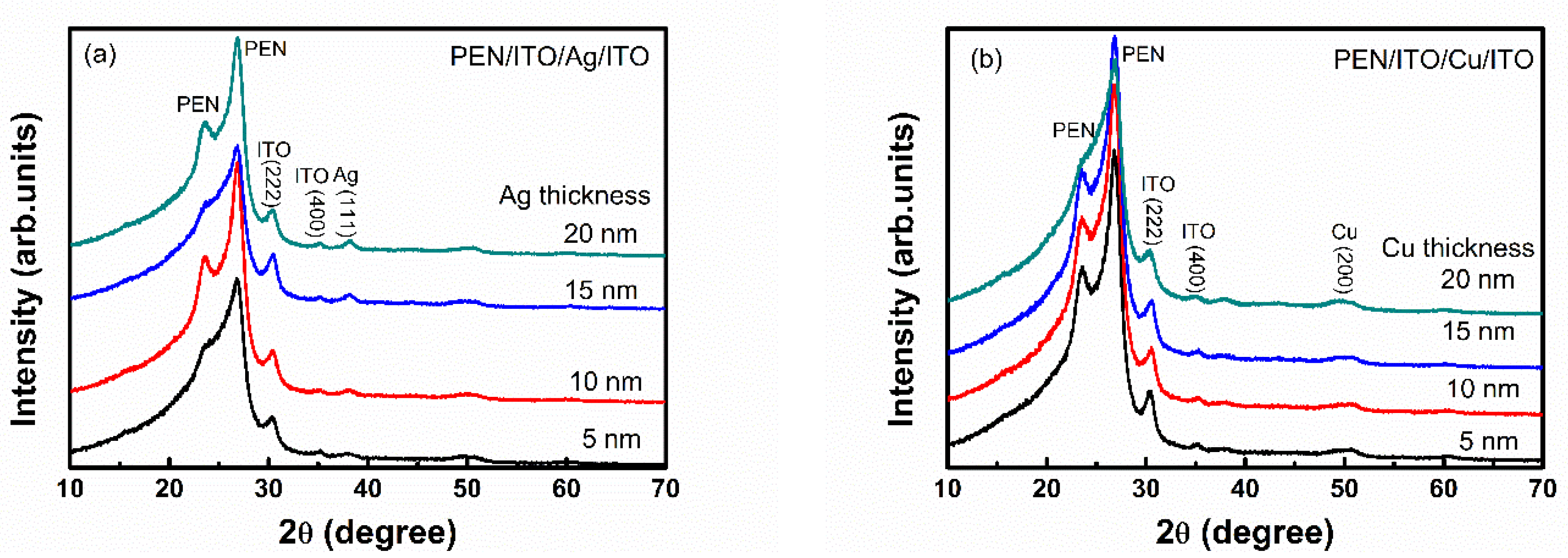
Figure 1. GIXRD plots obtained from (a) ITO/Ag/ITO and (b) ITO/Cu/ITO samples as functions of the Ag and Cu thick ness on the PEN substrate.
Coatings 11 00144 g001
Figure 2. Surface FESEM images of Ag (a,b) and Cu (c,d) layers with thicknesses of 5 and 10 nm grown on the bottom ITO layer deposited on the PEN substrate.
Coatings 11 00144 g002
Figure 3. AFM images of ITO/Ag/ITO samples with different Ag interlayer thicknesses: (a) 5 nm, (b) 10 nm, (c) 15 nm and (d) 20 nm.
Coatings 11 00144 g003
Figure 4. AFM images of ITO/Cu/ITO samples with different Cu interlayer thicknesses: (a) 5 nm, (b) 10 nm, (c) 15 nm and (d) 20 nm.
Coatings 11 00144 g004
Figure 5. XPS spectra of (a) Ag 3d and (b) Cu 2p for the IAgI and ICuI films on PEN substrate with the metal interlayer thickness of 10 nm.
Coatings 11 00144 g005
Figure 6. Optical transmittance of the (a) IAgI and (b) ICuI films as functions of the Ag and Cu thickness on PEN substrate.
Coatings 11 00144 g006
Figure 7. Transmittance at the wavelength of 550 nm and figure of merit of (a) IAgI and (b) ICuI samples as a function of the metal interlayer thickness on the PEN substrate.
Coatings 11 00144 g007
Table 1. The Ag (111) and Cu (200) crystallite sizes with different metal interlayer thicknesses on the PEN substrate (nm).
Thickness5 nm10 nm15 nm20 nm
Sample
Ag4678
Cu1112
Table 2. Electrical properties of ITO/Ag/ITO and ITO/Cu/ITO films on PEN substrate as functions of the Ag and Cu interlayer thickness on the PEN substrate.
PropertyITO/Ag/ITOITO/Cu/ITO
Metal layer thickness (nm)51015205101520
Concentration (×1022/cm3)1.291.772.362.411.392.8711.599.39
Mobility (cm2/Vs)0.985.395.276.382.252.310.621.45
Resistivity (×10−5 Ω/cm)48.856.585.034.0619.969.398.654.58
Sheet resistance (Ω/sq)57.477.295.294.0623.4810.439.114.58
Table 3. Largest ΦTC, minimum sheet resistance (Rs) and maximum optical transmittance of sandwich transparent conductive films deposited with various methods reported in this study and other literature.
ΦTC (10−3 Ω−1)Rs (Ω/sq)Transmittance (%; at 550 nm)StructureDeposition MethodReference
101.167.2997ITO/Ag (10 nm)/ITO/PENHiPIMSThis work
4.8310.4374ITO/Cu(10 nm)/ITO/PENHiPIMSThis work
6.668.9382.4ITO/Ag/ITO/PETRTR sputter[63]
64.576.491.4ITO/Ag/ITO/CPISputter + anneal[33]
246.783.2ITO/Ag/ITO/PETSputter[64]
36.66.1286.1MTO/Ag/MTO/PETSputter[53]
149.284AGZO/Ag/AGZO/PETRTR sputter[65]
4.1211.873.9ITO/Cu/ITO/PETRTR sputter[66]
0.523667ITO/Cu/ITO/PCSputter[29]
0.09414365SiO2/ITO/Cu/ITO/PETSputter + buffer layer[67]
Note: RTR: Roll to Roll.
Publisher’s Note: MDPI stays neutral with regard to jurisdictional claims in published maps and institutional affiliations.