Article

Superhydrophilic Coating of Pine Wood by Plasma Functionalization of Self-Assembled Polystyrene Spheres

1
Institute of Energy Research and Physical Technologies, Clausthal University of Technology, Leibnizstr. 4, 38678 Clausthal-Zellerfeld, Germany
2
Department of Wood Science and Technology, Biotechnical Faculty, University of Ljubljana, Jamnikarjeva ulica 101, 1000 Ljubljana, Slovenia
3
Clausthal Centre for Material Technology, Clausthal University of Technology, Agricolastr. 2, 38678 Clausthal-Zellerfeld, Germany
4
Institute of Electrochemistry, Clausthal University of Technology, Arnold-Sommerfeld-Str. 6, 38678 Clausthal-Zellerfeld, Germany
5
Faculty of Engineering and Health, University of Applied Sciences and Arts, Von-Ossietzky-Str. 99, 37085 Göttingen, Germany
*
Author to whom correspondence should be addressed.
Coatings 2021, 11(2), 114; https://doi.org/10.3390/coatings11020114
Submission received: 11 December 2020 / Revised: 7 January 2021 / Accepted: 12 January 2021 / Published: 20 January 2021

Abstract

:
Self-assembling films typically used for colloidal lithography have been applied to pine wood substrates to change the surface wettability. Therefore, monodisperse polystyrene (PS) spheres have been deposited onto a rough pine wood substrate via dip coating. The resulting PS sphere film resembled a polycrystalline face centered cubic (FCC)-like structure with typical domain sizes of 5–15 single spheres. This self-assembled coating was further functionalized via an O2 plasma. This plasma treatment strongly influenced the particle sizes in the outermost layer, and hydroxyl as well as carbonyl groups were introduced to the PS spheres’ surfaces, thus generating a superhydrophilic behavior.

1. Introduction

The deposition of self-assembling films has been developed from colloidal particle films [1,2]. The thickness of these films can be controlled between monolayers and several microns by varying the deposition parameters [3,4]. It has been found that monodisperse colloidal spheres are especially useful to deposit self-assembled films, sometimes enhanced by surfactants [5]. Such self-assembled films offer a great potential for many manufacturing methods due to their periodicity or crystallinity, and they are often referred to as nanosphere lithography or colloidal lithography [6]. Even the use of different particles and spheres can be carried out, thus gaining multicolloidal crystals [7]. The applications of these crystals include biosensors [8], chemical sensors [9], high-strength ceramics, optical sensors and templates for macroporous structure synthesis [10,11]. Polystyrene colloidal crystals can be used for the preparation of macroporous films [12] and conducting polymers [13]. The self-assembly induces periodicities in dimensions high enough to form photonic crystals [10,14]. One critical issue for many of the given applications is the roughness of the substrate’s surface, onto which the layers are applied, because it accounts for the degree of ordering. The rougher the surface, the less perfect the arrangement of the spheres becomes [15]. For patterning nonplanar surfaces, colloidal lithography is also applicable [16].
The highly ordered structures obtained by self-assembly of spheres strongly influence the surface wettability, ranging from superhydrophilic to superhydrophobic behavior [17]. Lotus leaves with their self-cleaning ability show a multiscale roughness [18,19] together with superhydrophobic properties [20]. Several different approaches have been made to yield such a roughened texture [21,22]. First successful attempts to obtain films of self-assembled spheres on rough surfaces have been made by Allard et al., depositing polymethyl methacrylate spheres onto paper substrates via spray coating [23]. However, the method used by Allard et al. depends on the draining of the solvent through the substrate. For impermeable substrates with similar roughness, no successful application has been published until now. Nevertheless, the colloidal lithography can be considered as an easy method to protect damageable organic surfaces. One example for rough organic surfaces with the need of protection against soaking with water are wood surfaces, since the decay of wood is mainly driven by fungi and bacteria, which can only survive in damp wood. Such self-assembling colloidal arrays have been widely investigated for usage as photonic crystals [24,25]. The fabrication of these films can be scaled up to large areas [26,27] for applications such as color patterns and color-changing paints, even in the automotive industry [28], thin-film optics [29], electric applications, such as solar cells [28,30], or solarthermal applications [31]. Among further applications of colloidal crystallization techniques is the fabrication of superhydrophobic, superamphiphobic, or superhydrophilic surfaces [32,33].
Similar superhydrophobic characteristics have been creating on wood and lignocellulosic substrates using soot from flames [22,33,34,35]. However, this suffered from the visual appearance and required further steps for fixation of the particles to achieve mechanical durability [36,37]. Moreover, for wood and other roughly structured substrates, this typically requires varnishes or primer films to smoothen the surface [38,39], with some authors even concluding a direct deposition of such coatings from suspensions onto wood were not possible due to the substrates natural structure [40]. On wood substrates precoated e.g., with a polydimethylsiloxane (PDMS) film though, spray-coated nanocomposites were superhydrophobic, mechanically durable and self-healing [41].
Other approaches include fluorine functionalized superamphiphobic latex-type coatings that are cured at elevated temperatures [42]. Similar coatings were reported with improved mechanic durability and high transparency at the cost of a reduction of the superhydrophobicity [43]. Even more elaborate is the production of superhydrophobic or superamphiphobic films on lignocellulosic substrates by magnetron sputtering in high vacuum [44,45].
Another possible, but much less investigated application for self-assembling colloidal arrays are superhydrophilic films [46]. The concept of superhydrophilic coatings is similarly connected to hierarchical structures, but includes a different chemical functionality [47,48]. Superhydrophilic surfaces are an alternative approach to self-cleaning surfaces, which in some cases has been shown to outperform superhydrophobic surfaces [49]. Both, opaline pigments [23] and self-cleaning coatings are promising for applications in the wood sectors, although requiring an additional fixation of the colloidal arrays. Moreover, wettability generally plays an important role for many application on wooden work pieces [50], including for coatings [51,52], adhesive bonding [53] and fabrication of composites [54], particularly in the prevention of interfacial voids [55].
In this work, we demonstrate the applicability of self-assembling colloidal arrays on wood as a surface with initially high chemical and structural heterogeneities. Further, the etching of the colloidal arrays by means of an air plasma is shown, which allows to set up colloidal templates and photonic crystals with defined geometric dimensions. Moreover, the functionalization that occurs during the plasma etching yields a chemical functionalization that leads to a superhydrophilic film with potential applications as base coat, adhesion promoter or basis for self-cleaning surfaces.

2. Materials and Methods

A Digital Microscope (Keyence VHX-1000D with VH-Z100UW objective) is used for Light Microscopy (LM). The microscope allows a magnification from 100× to 1000×. The depth of sharpness is increased by merging several pictures.
Confocal Laser Scanning Microscopy (CLSM) was employed to study surface topographies previous and subsequent to the plasma treatments, thus allowing for a verification of the SEM results, which possibly may be affected by surface charging. Due to the roughness of the surfaces, no AFM images with similar fields of view as the SEM images could be obtained. The Keyence VK-X210 microscope with VK-X200K controller has a total magnification up to 24,000×, this consists of up to 150× objective lens magnification (Mo), up to 8× optical zoom and further digital magnification. A laser with a wavelength of 408 nm is used for the illumination. For all images shown here, objectives with Mo = 10× (N.A. = 0.3) and Mo = 150× (N.A. = 0.95) were used. The images are overlaid with wide field microscopic and laser intensity measurements.
A Scanning Auger Electron Microscope (Omicron NanoSAM, Uppsala, Sweden) with a base pressure below 10−10 hPa is used for Scanning Electron Microscopy (SEM) (c.f. successor equipment Scienta Omicron NanoScan Lab [56]). No conductive coating has been applied to the samples prior to the SEM measurements, thus enabling us to retrieve images of the same sample before and after plasma functionalization. However, no Auger electron spectroscopy measurements can be conducted due to charging of the surface. The beam current during operation was 200 pA at a primary electron energy of 2 keV with a typical spatial resolution of 3 nm for SEM.
Atomic Force Microscopy (AFM) was carried out using a Veeco Dimension 3100 SPM (Veeco Instruments Inc. 112 Robin Hill Road Santa Barbara CA 93117, Goleta, CA, USA). All measurements are performed in Tapping Mode with Al-coated silicon cantilevers (NSC15, Micromasch). The typical resonance frequencies of this series are about 325 kHz, typical spring constants are in the range of 40 N/m. The radius of the tip curvature is less than 10 nm. All images consist of 512 lines each containing 512 pixels. They are recorded with a line-scan frequency of 0.5 Hz. SPIP (Image Metrology A/S) is used for the depiction of the AFM images and the calculation of the root mean square (RMS) surface roughness according to ISO 4287/1 [57].
An Ultra High Vacuum (UHV) apparatus with a base pressure of 5 × 10⁻¹¹ hPa was used to carry out the spectroscopic experiments [58]. Scanning Electron Microscopy was performed in another UHV apparatus [59]. Atomic Force Microscopy and Confocal Laser Scanning Microscopy were carried out at atmospheric air. All measurements were performed at room temperature.
X-ray Photoelectron Spectroscopy (XPS) was performed using a hemispherical analyser (VSW HA100, VSW Atomtech Ltd., Witney, Oxfordshire, UK) in combination with a commercial non-monochromatic X-ray source (Specs RQ20/38C). During XPS, X-ray photons irradiate the surface under an angle of 80° to the surface normal, illuminating a spot with a diameter of several mm. For all measurements presented here the Al Kα line (photon energy 1486.6 eV) is used. Electrons were recorded by the hemispherical analyzer with an energy resolution of 1.1 eV emitted under an angle of 10° to the surface normal. All XPS spectra are displayed as a function of binding energy with respect to the Fermi level.
For quantitative XPS analysis, photoelectron peak areas were calculated via mathematical fitting with Gauss-type profiles using CasaXPS to achieve the best agreement possible between experimental data and fit. To optimize our fitting procedure, Voigt-profiles were applied to various oxidic and metallic systems previously, but for most systems the Lorentzian contribution converged to zero. Therefore, all XPS peaks were fitted with Gaussian shapes. For the analysis of all of the spectra, a Shirley-type background has been used. Photoelectric cross sections as calculated by Scofield [60] with asymmetry factors after Powell and Jablonski [61], taking into account asymmetry parameters after Reilman et al. [62] and Jablonski [63] as well as inelastic mean free paths from the NIST database [64] (using the database of Tanuma, Powell and Penn for elementary contributions and the TPP-2M equation for molecules), as well as the energy dependent transmission function of our hemispherical analyser are taken into account when calculating the stoichiometry.
Pine wood veneer with a thickness of about 0.7 mm were cut into pieces of approximately 10 × 100 mm2 prior to the PS sphere dip coating process. The coated pine wood sample was then cut into chips of 10 × 10 mm2 for further investigations.
The self-assembled polystyrene structures are prepared on the pine wood veneer chips by dipping in a suspension of polystyrene (PS) spheres (OptiBind®, d = 600 nm, previous catalog no. 11001397100390 at Seradyn, Inc. (Indianapolis, IN, USA), now catalog no. 91001397100390 at Thermo Fisher). The initial suspension was washed several times with water to remove commercial stabilizers and additives, after each washing step the spheres were centrifuged, and at last dispersed at an amount of 10 vol. % in ethanol. The film deposition was carried out at 40 °C by dipping of the substrate into the dispersion, resting in the dispersion for 1 s, and subsequent manual pulling out at an angle of approx. 40°–45° and a velocity of approx. 5 mm/s [65]. Similar flow-induced processes reported in literature result in well defined multilayer colloidal crystals [4,25,66]. The self-assembly of layers occurs, as capillary forces drive the dispersed polymer spheres into the wetting meniscus during the lifting process. The concentration of spheres lifting speed are main parameters that define the film thickness or number of layers of particles [32], further influences are presented by the wetting behavior of the dispersion on the substrate’s surface and the solvent’s evaporation rate. The self-assembled films were not subjected to any additional rinsing in order to exclude any impact.
Plasma treatments were carried out employing a dielectric barrier discharge in 200 hPa oxygen (99.99%, Westfalen AG). The plasma source has been described in detail elsewhere [67]. A brass-filled sealed quartz glass tube with a wall thickness of 2.4 mm is used as isolated high voltage electrode, which is mounted to a preparation chamber with a base pressure of 5 × 10⁻⁸ hPa which is connected directly to the UHV recipient via a common transfer system. An alternating high voltage pulse generator with a pulse duration of 0.6 μs and a pulse repetition rate of 10 kHz is connected to the dielectric isolated electrode, while the sample forms the grounded counter electrode. The discharge gap was set to about 1 mm and the discharge area is about 2 cm2. During the plasma treatment, a voltage of 11 kV (peak) is measured. The high voltage supply delivers a power of 2 W, the plasma power density can be calculated to 1 W/cm2 and with a plasma treatment time of 300 s, an energy density of 300 J/cm2 is applied to the sample. The increase of the sample temperature during the plasma treatment does not exceed 10 K [34,68]. Typical electron energies with this setup amounted to approx. 7 eV [7,69].
Contact angles have been measured via the sessile drop method, using a Nikon D60 on a tripod together with a AF-S DX NIKKOR 18–105 mm/3.5–5.6G ED VR zoom lens. Deionized water drops were deposited by a commercial syringe. Contact angles have been estimated using the LB-ADSA method of the Drop Analysis plugin for the ImageJ image processing program [70]

3. Results and Discussion

The pine wood samples coated with self-assembling PS spheres have been characterized by a variety of microscopic tools, thus overcoming the single disadvantages of every of these methods. Since the optical appearance of the coating is of interest for many of the possible applications, the presented results begin with a LM image. CLSM has been used to study the structuring of the films over large scales. Scanning Electron Microscopy has been employed without any conductive coating. This allows to take images of the very same sample before and after plasma treatments, even though the occurrence of charging might affect the obtained images. However, it is a powerful tool to overcome the wavelength limitation of the Confocal Laser Scanning Microscope’s field of view and thus closing the gap to the field of view for the Atomic Force Microscope. These microscopic studies of the coating and the influence of an air plasma treatment are then compared to the results on their chemical structure.

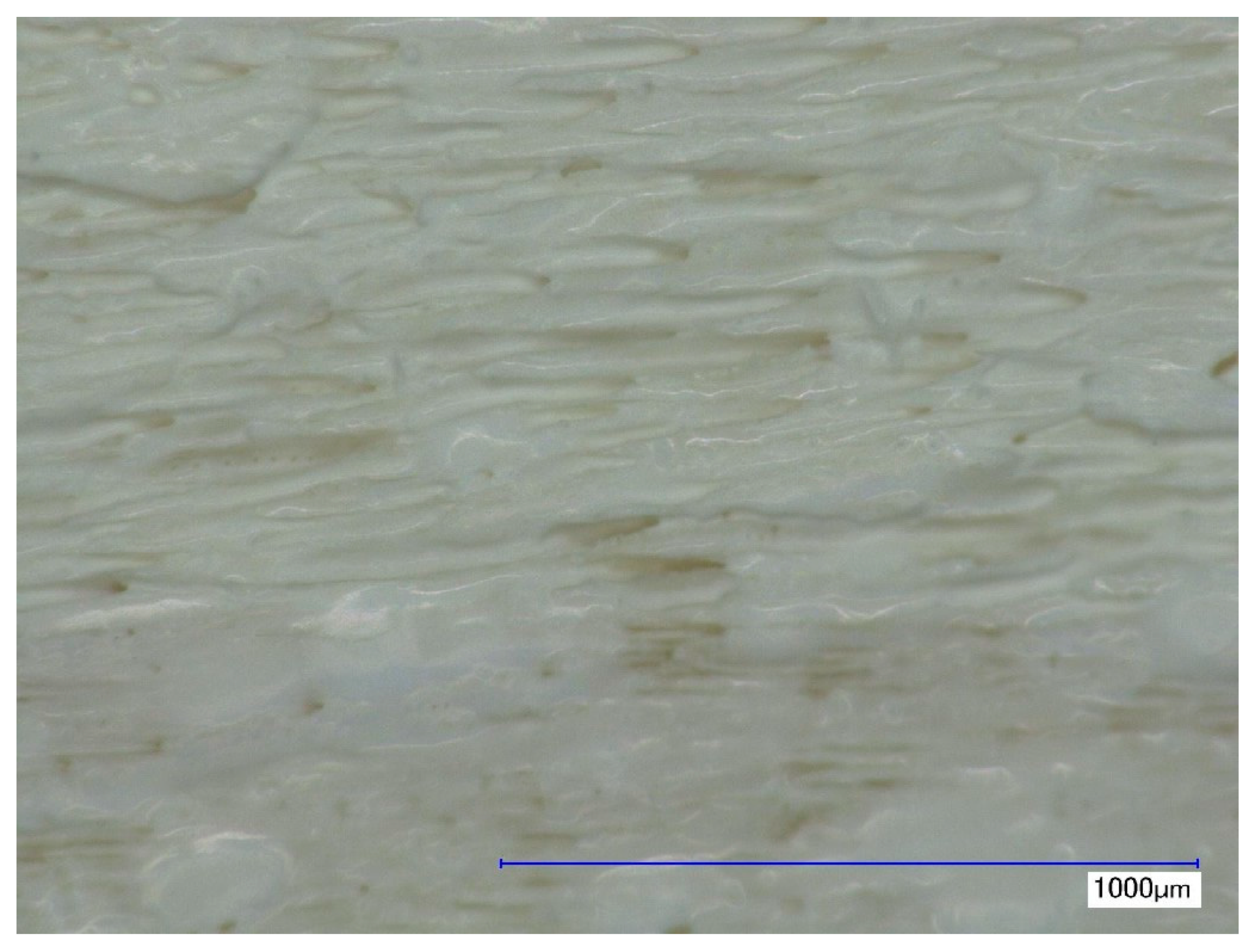
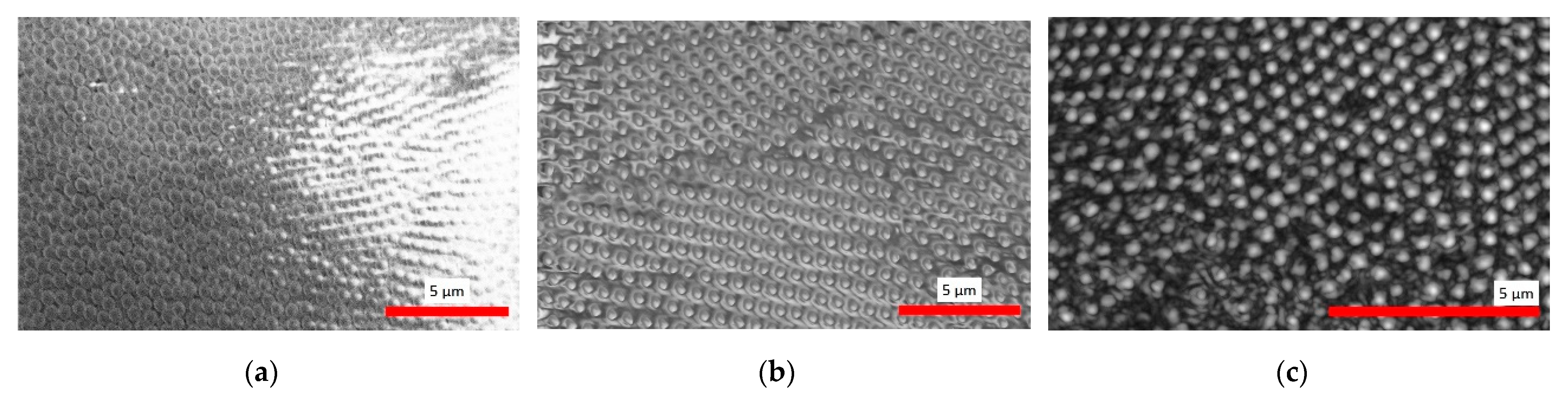
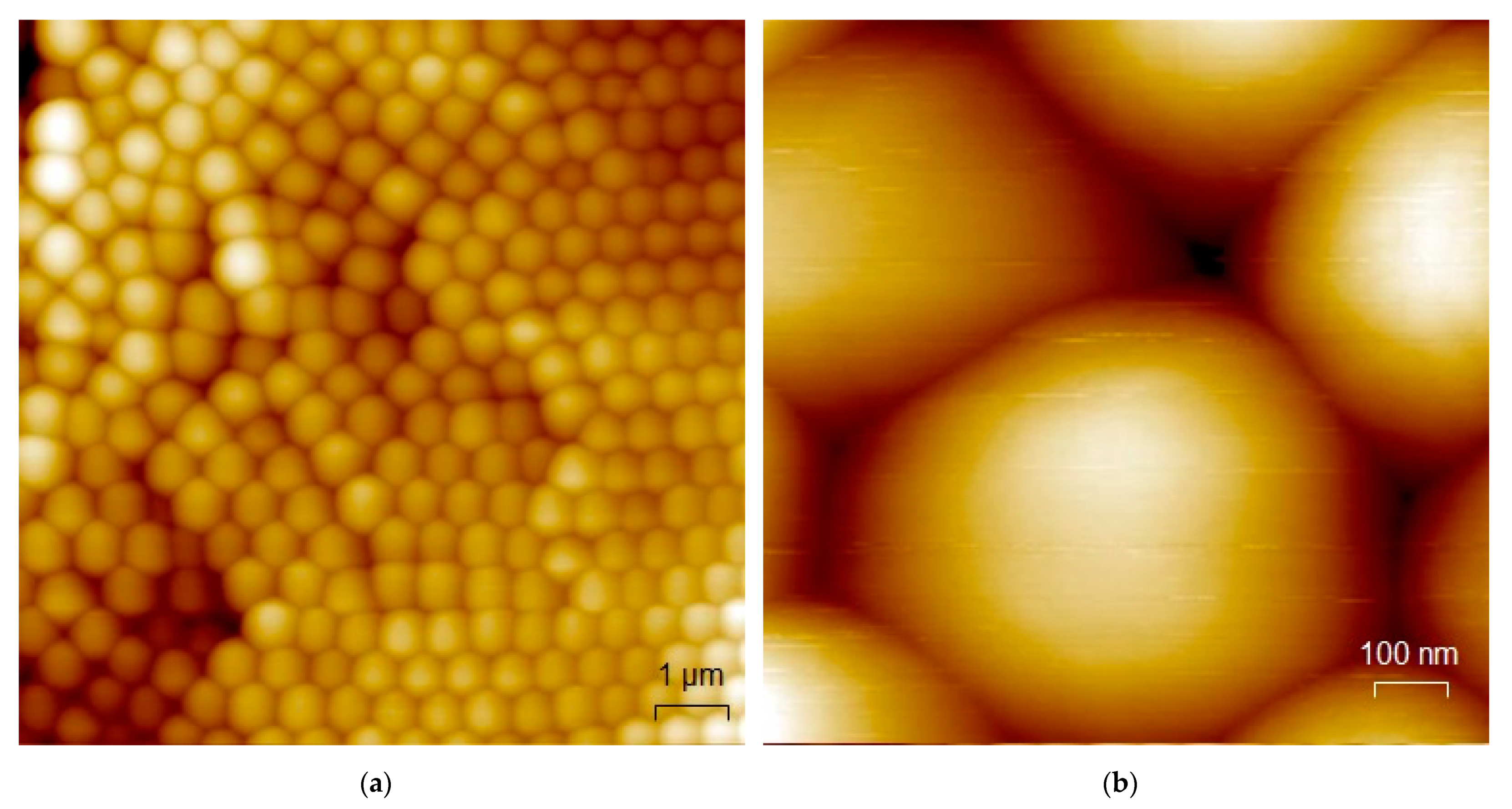
3.1. Microscopic Characterization

Figure 1 shows a light microscopic image of the PS sphere coated pine wood sample. The coating follows the natural structure of the wood substrate quite well on a rather macroscopic scale. The film thickness however seems to be unsteady. At some parts of the sample, the color of the substrate is still visible, whereas most parts are colored completely white by the PS spheres. The color, however, originates in the latex-type structure of the film, which causes a diffuse reflection of the incident light while actually the spheres are transparent [71]. Thus, the film thickness can hardly be estimated from the color of the film. The films obtained with the employed deposition method tend to have a film thickness of about 10–12 layers on smooth surfaces [72,73]. However, the roughness of the wood substrate might give rise to slightly higher film thicknesses.
Figure 2 displays CLSM images of the PS sphere coated pine wood sample before (a, left image) and after O2 plasma treatment (b, right image) with a magnification of 1500× (95 × 71 µm2) in both images. The red bar indicates a horizontal length of 10 µm. Main parts of the obtained film of PS spheres are polycrystalline with typical domain sizes of about 5–15 single spheres, where the PS spheres are mainly resembling a face-centered cubic (FCC) crystal lattice. In the top image there is a rift visible which has not been filled up with PS spheres. Around this rift, the PS spheres assemble in an amorphous way, at some parts even revealing incomplete covering. The right image (b) pictures a rift, which is fully filled with PS spheres in an amorphous structure. However, no difference between the periodicity of the PS sphere film’s structure of the plasma treated sample (b) and the untreated sample (a) is visible. The root mean square roughness Rq over the ordered domains amounts to approx. 4.4 µm before plasma and 2.7 µm after plasma. This likely originates in the reduced height of the PS spheres after the plasma etching, which yields a reduction in observable height differences within the CLSM data.
Figure 3 exhibits SEM images of the PS sphere coated pine wood sample before (a, left image) and after O2 plasma treatment (b, middle image) with image sizes of 16 × 21 µm2 and 11 × 15 µm2 respectively, as well as a CLSM image after the O2 plasma treatment (c, right image) with a magnification of 12,000× (11.9 × 8.9 µm2). The red bar indicates a horizontal length of 5 µm. The SEM image reveal that the spheres are densely packed prior to the plasma treatment. After the plasma treatment, the SEM image shows gaps between the PS spheres, which are still arranged in a FCC-like manner, even though the spheres are now shrunk to about half of their size. The CLSM image after O2 plasma treatment (c) shows just the same influence of the plasma treatment as the SEM image, thus excluding misleading results due to possible charging effects. It is noteworthy, that the distances between PS spheres remains the same throughout the plasma etching, whereas the diameter of the outermost layers is significantly reduced. This indicates a minor influence of repulsive forces, such as electrostatic repulsion or hydration forces. This is consistent to earlier plasma applications on similar self-assembled PS layers [39,72]. Additional SEM images after O2 plasma treatment are available in the (supplemental materials Figure S1).
Figure 4 presents AFM images of the PS sphere coated pine wood sample with a field of view of 10 × 10 µm2 (a, left image) and 1 × 1 µm2 (b, right image), respectively. Near surface parts with higher roughness, stacking errors and even amorphous phases are visible. The size of the spheres amounts to about 0.61 µm which fits very well to the manufacturer information and thus excludes broadening effects due to the AFM tip. The AFM results after the plasma treatment (not shown) resemble exactly the images prior to the plasma treatment (see Figure 4), in contrast to the SEM images clearly showing etched layers of spheres. This indicates a lack of mechanical strength of the sphere-based coating, as the affected layers are apparently removed by performing contact AFM measurements.

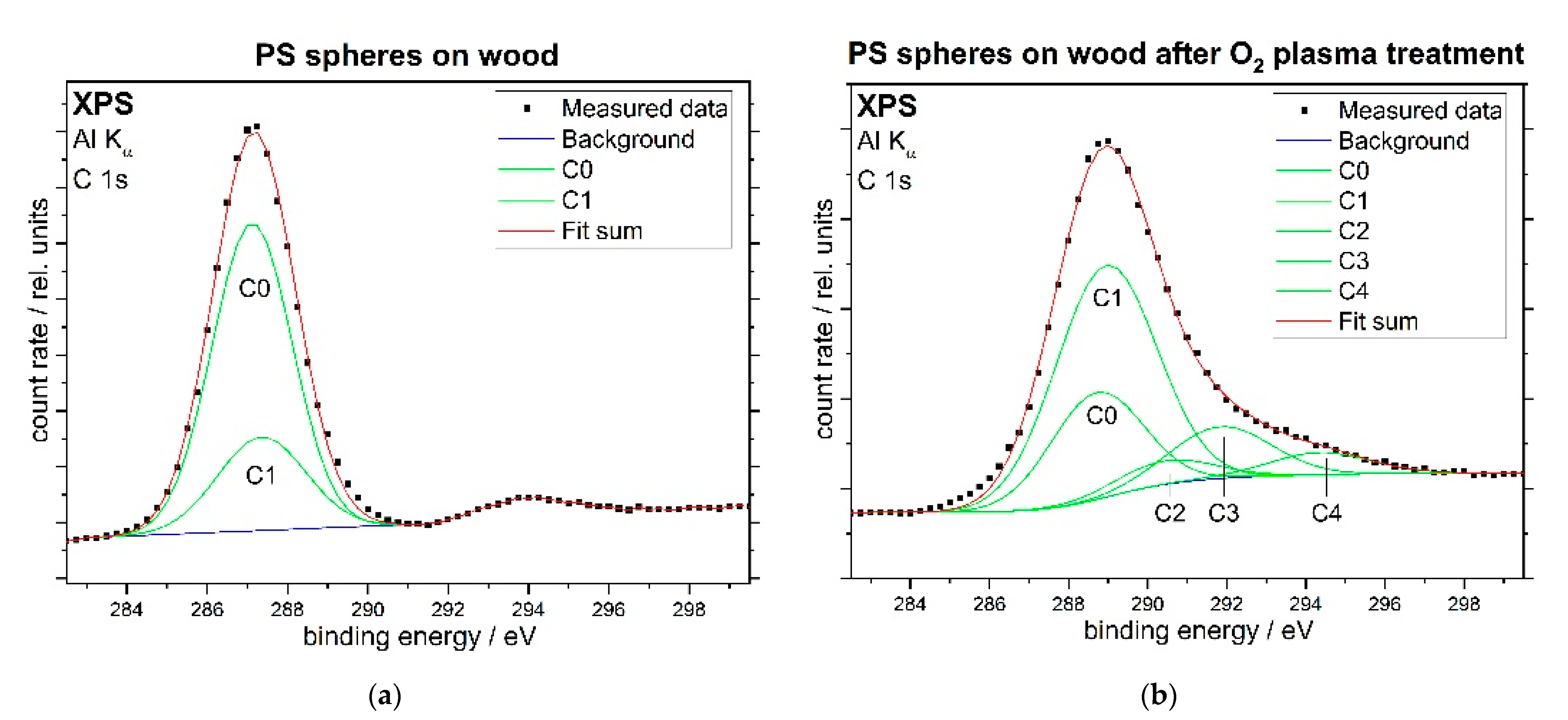
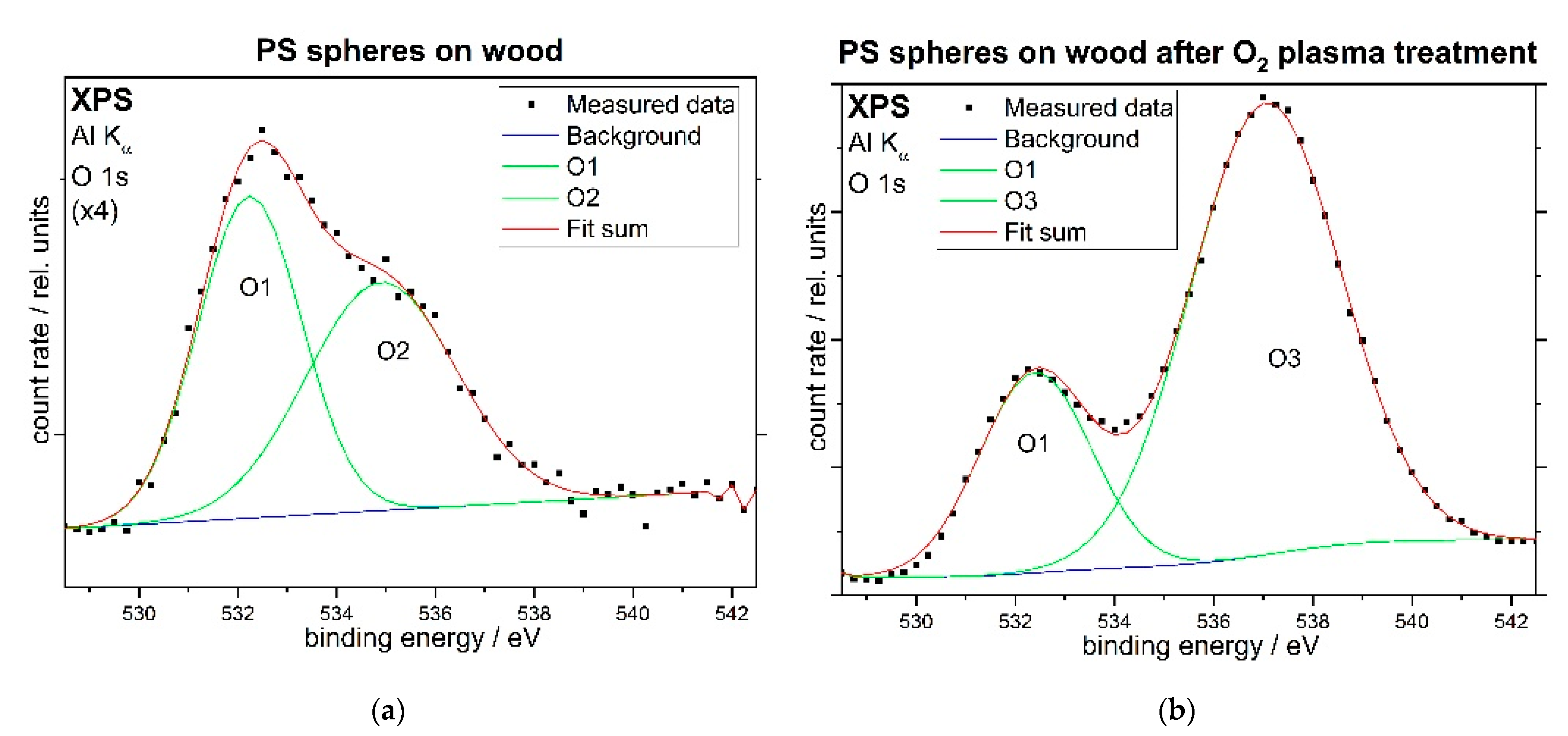
3.2. Spectroscopic Characterization

Figure 5 shows XPS C 1s spectra of the PS sphere coated pine wood sample before (a, left image) and after O2 plasma treatment (b, right image). The black points represent the original data, the Gaussian peaks of the individual components are displayed using green lines, while the sum for each spectrum is shown as red line. During the fitting procedure, the relative binding energies of the features have been set after Beamson and Briggs [74] as summarized in Table 1. Before the plasma treatment, the C 1s spectrum consists solely of aliphatic and aromatic groups. Due to the resolution limits, the ratios for peak areas and full widths at half mean (FWHM) have also been fixed for this fit. After the plasma treatment, some additional peaks are apparent, indicating an amount of oxidized carbon atoms of about 22%.
Figure 6 displays XPS O 1s spectra of the PS sphere coated pine wood sample before (a, left image) and after O2 plasma treatment (b, right image). The spectrum before plasma treatment is enlarged due to its small intensity, which solely originates from the sample holder. After the plasma treatment, the oxide state from the sample holder is still present, but a larger peak has appeared at higher binding energies due to the hydroxyl, alkoxy, carbonyl and carboxyl groups that have been generated on the polystyrene spheres by the plasma treatment.
All XPS C 1s and O 1s results from Figure 5 and Figure 6 are summarized in Table 2. Contact angles estimated via the Sessile drop method were 84° for the uncoated wood substrate and 110° for the PS sphere coated wood prior to the plasma treatment, while the contact angle of the PS sphere coated wood sample after the plasma treatment was well below 10° and thus incapable of measurement. Water contact angles are exemplarily displayed in Figure 7 before (a) and after plasma treatment (b), as opposed to water contact angles on the uncoated pine wood substrate (c). One factor that has been introduced with high relevance to amphiphilic behaviours is the hydration state of layers of polymer particles and molecules encompassing different functionalities [75]. Although the reduced roughness and possible hydration effects may play a role, the hydrophilic effect is most likely to be caused foremost through the addition of the polar oxygen-containing groups to the previously non-polar, hydrophobic polystyrene. However, the porous structure and hydration effects may well add to this, thus giving rise to the particularly strong wetting that was observed on the plasma-treated surfaces.
These self-assembling colloidal films can be considered as one part of deposition process for self-cleaning coatings. Even though the results appear very promising, there are two issues that have to be overcome in order to use the coating in any application. Firstly, the film has to be fastened to gain mechanical stability. Secondly, the surface energy has to be varied e.g., via the attachment of surfactants, thus creating a lotus-effect film. Therefore, the overall coating process of such films can be subdivided into the following steps:
  • Deposition of the self-assembling units
  • Fixation of this colloidal film
  • Simultaneous plasma etching and functionalization
  • Attaching surfactant molecules
The colloidal deposition step (1) has successfully been carried out as demonstrated earlier in this section. The fixation step (2) however still has to be developed. The plasma-etching step (3) has successfully been demonstrated as well, where the results on the C 1s structure after the plasma treatment indicated a high amount of polar groups. These polar groups can then presumably be used as bonding sites for the attachment of surfactant molecules to adapt the surface energy corresponding to the film (step 4). This last step is crucial for the hydrophobic properties of the film and may even lead to an amphiphobization e.g., when using organofluorine compounds.

4. Conclusions

The microscopic results reveal a polycrystalline FCC structure of the PS sphere coating with typical domain sizes of 5–15 single spheres. The O2 plasma treatment significantly shrank the PS spheres without any influence on the crystal-like structure. Furthermore, the surface of the PS spheres got chemically modified towards hydroxyl and carbonyl groups. This two-part, chemical and structural functionalization of the PS spheres induced very low, superhydrophilic contact angles. However, the coating did not become stabilized by the plasma treatment. Thus, some further treatment has to be applied in order to make the film applicable. A promising approach for the fixation of the film is the plasma polymerization of a further polymer matrix. Moreover, the chemical groups attached to the PS spheres by the O2 plasma treatment can be utilized to attach functional groups in order to try and improve the chemical resistance or generate very high, superhydrophobic contact angles. These tasks will be addressed in prospective investigations.

Supplementary Materials

The following are available online at https://www.mdpi.com/2079-6412/11/2/114/s1, Figure S1: SEM images of larger areas of the PS sphere coated pine wood sample after O2 plasma treatment.

Author Contributions

Conceptualization, S.D.; formal analysis, S.D.; investigation, S.D., J.M., R.G., and A.P.; resources, W.M.-F.; data curation, S.D.; writing—original draft preparation, S.D.; writing—review and editing, A.P., W.V., and W.M.-F.; visualization, S.D.; supervision, W.V. and W.M.-F.; project administration, W.M.-F.; funding acquisition, S.D., W.V., and W.M.-F. All authors have read and agreed to the published version of the manuscript.

Funding

This research was funded by the Deutsche Forschungsgemeinschaft (DFG), grant numbers MA 1893/18-1 and VI 359/9-1.

Data Availability Statement

All raw and analyzed data have been made available through Zenodo at https://doi.org/10.5281/zenodo.4290000.

Acknowledgments

We gratefully acknowledge the technical assistance of Dana Schulte genannt Berthold (AFM) and Silvia Löffelholz (LM, CLSM), the group of W. Daum (Institute of Energy Research and Physical Technologies, TU Clausthal) for providing the atomic force microscope, and the preparation of the pine wood substrates by the group of Professor H. Militz (Department of Wood Biology and Wood Products, Georg-August-Universität Göttingen), as well as the financial support by the Deutsche Forschungsgemeinschaft (DFG) under project numbers MA 1893/18-1 and VI 359/9-1.

Conflicts of Interest

The authors declare no conflict of interest. The funders had no role in the design of the study; in the collection, analyses, or interpretation of data; in the writing of the manuscript, or in the decision to publish the results.

References

  1. Nagayama, K.; Dimitrov, A.S. Fabrication and Application of Particle-Crystalline Films. ACS Symp. Ser. 1996, 648, 468–489. [Google Scholar]
  2. Dimitrov, A.S.; Nagayama, K. Continuous Convective Assembling of Fine Particles into Two-Dimensional Arrays on Solid Surfaces. Langmuir 1996, 12, 1303–1311. [Google Scholar] [CrossRef]
  3. Sato, T.; Hasko, D.G.; Ahmed, H. Nanoscale colloidal particles: Monolayer organization and patterning. J. Vac. Sci. Technol. B 1997, 15, 45–48. [Google Scholar] [CrossRef]
  4. Jiang, P.; Bertone, J.F.; Hwang, K.S.; Colvin, V.L. Single-Crystal Colloidal Multilayers of Controlled Thickness. Chem. Mater. 1999, 11, 2132–2140. [Google Scholar] [CrossRef]
  5. Pillai, S.; Hemmersam, A.G.; Mukhopadhyay, R.; Meyer, R.L.; Moghimi, S.M.; Besenbacher, F.; Kingshott, P. Tunable 3D and 2D polystyrene nanoparticle assemblies using surface wettability, low volume fraction and surfactant effects. Nanotechnology 2009, 20, 025604. [Google Scholar] [CrossRef] [PubMed]
  6. Masson, J.-F.; Murray-Méthot, M.-P.; Live, L.S. Nanohole arrays in chemical analysis: Manufacturing methods and applications. Analyst 2010, 135, 1483–1489. [Google Scholar] [CrossRef]
  7. Singh, G.; Pillai, S.; Arpanaei, A.; Kingshott, P. Multicomponent colloidal crystals that are tunable over large areas. Soft Matter 2011, 7, 3290–3294. [Google Scholar] [CrossRef]
  8. Asher, S.A.; Alexeev, V.L.; Goponenko, A.V.; Sharma, A.C.; Lednev, I.K.; Wilcox, C.S.; Finegold, D.N. Photonic Crystal Carbohydrate Sensors: Low Ionic Strength Sugar Sensing. J. Am. Chem. Soc. 2003, 125, 3322–3329. [Google Scholar] [CrossRef]
  9. Holtz, J.H.; Asher, S.A. Polymerized colloidal crystal hydrogel films as intelligent chemical sensing materials. Nature 1997, 389, 829–832. [Google Scholar] [CrossRef]
  10. Xia, Y.; Gates, B.; Yin, Y.; Lu, Y. Monodispersed Colloidal Spheres: Old Materials with New Applications. Adv. Mater. 2000, 12, 693–713. [Google Scholar] [CrossRef]
  11. Bartlett, P.N.; Baumberg, J.J.; Birkin, P.R.; Ghanem, M.A.; Netti, M.C. Highly Ordered Macroporous Gold and Platinum Films Formed by Electrochemical Deposition through Templates Assembled from Submicron Diameter Monodisperse Polystyrene Spheres. Chem. Mater. 2002, 14, 2199–2208. [Google Scholar] [CrossRef]
  12. Carstens, T.; Prowald, A.; El Abedin, S.Z.; Endres, F. Electrochemical synthesis of PEDOT and PPP macroporous films and nanowire architectures from ionic liquids. J. Solid State Electrochem. 2012, 16, 3479–3485. [Google Scholar] [CrossRef]
  13. Al Zoubi, M.; Al-Salman, R.; Li, Y.; Endres, F. Highly Ordered 3D-Macroporous Poly(Para-Phenylene) Films Made by Electropolymerization of Benzene in an Ionic Liquid. Z. Phys. Chem. 2011, 225, 393–403. [Google Scholar] [CrossRef]
  14. Nagayama, K. Two-dimensional self-assembly of colloids in thin liquid films. Colloid. Surf. A 1996, 109, 363–374. [Google Scholar] [CrossRef]
  15. Gasparotto, L.H.S.; Prowald, A.; Borisenko, N.; El Abedin, S.Z.; Garsuch, A.; Endres, F. Electrochemical synthesis of macroporous aluminium films and their behavior towards lithium deposition/stripping. J. Power Sour. 2011, 5, 2879–2883. [Google Scholar] [CrossRef]
  16. Bhawalkar, S.P.; Qian, J.; Heiber, M.C.; Jia, L. Development of a Colloidal Lithography Method for Patterning Nonplanar Surfaces. Langmuir 2010, 26, 16662–16666. [Google Scholar] [CrossRef]
  17. Koch, K.; Bhushan, B.; Barthlott, W. Diversity of structure, morphology and wetting of plant surfaces. Soft Matter 2008, 4, 1943–1963. [Google Scholar] [CrossRef]
  18. Solga, A.; Cerman, Z.; Striffler, B.F.; Spaeth, M.; Barthlott, W. The dream of staying clean: Lotus and biomimetic surfaces. Bioinspir. Biomim. 2007, 2, S126–S134. [Google Scholar] [CrossRef]
  19. Nosonovsky, M. Multiscale Roughness and Stability of Superhydrophobic Biomimetic Interfaces. Langmuir 2007, 23, 3157–3161. [Google Scholar] [CrossRef]
  20. Koch, K.; Bhushan, B.; Jung, Y.C.; Barthlott, W. Fabrication of artificial Lotus leaves and significance of hierarchical structure for superhydrophobicity and low adhesion. Soft Matter 2009, 5, 1386–1393. [Google Scholar] [CrossRef]
  21. Tuteja, A.; Choi, W.; Ma, M.; Mabry, J.M.; Mazzella, S.A.; Rutledge, G.C.; McKinley, G.H.; Cohen, R.E. Designing Superoleophobic Surfaces. Science 2007, 318, 1618–1622. [Google Scholar] [CrossRef] [PubMed] [Green Version]
  22. Deng, X.; Mammen, L.; Butt, H.-J.; Vollmer, D. Candle Soot as a Template for a Transparent Robust Superamphiphobic Coating. Science 2012, 335, 67–70. [Google Scholar] [CrossRef] [PubMed]
  23. Allard, D.; Lange, B.; Fleischhaker, F.; Zentel, R.; Wulf, M. Opaline effect pigments by spray induced self-assembly on porous substrates. Soft Mater. 2005, 3, 121–131. [Google Scholar] [CrossRef]
  24. Wang, C.; Lin, X.; Schäfer, C.G.; Hirsemann, S.; Ge, J. Spray Synthesis of Photonic Crystal Based Automotive Coatings with Bright and Angular-Dependent Structural Colors. Adv. Function. Mater. 2020, 134, 2008601. [Google Scholar] [CrossRef]
  25. Lange, B.; Fleischhaker, F.; Zentel, R. Functional 3D photonic films from polymer beads. Phys. Status Solidi A 2007, 204, 3618–3635. [Google Scholar] [CrossRef]
  26. Sprafke, A.N.; Schneevoigt, D.; Seidel, S.; Schweizer, S.L.; Wehrspohn, R.B. Automated spray coating process for the fabrication of large-area artificial opals on textured substrates. Opt. Express 2013, 21, A528. [Google Scholar] [CrossRef]
  27. Wei, J.; Zhang, G.; Dong, J.; Wang, H.; Guo, Y.; Zhuo, X.; Li, Y. Facile, Scalable Spray-Coating of Stable Emulsion for Transparent Self-Cleaning Surface of Cellulose-Based Materials. ACS Sustain. Chem. Eng. 2018, 6, 11335–11344. [Google Scholar] [CrossRef]
  28. Kim, J.B.; Lee, S.Y.; Lee, J.M.; Kim, S.-H. Designing Structural-Color Patterns Composed of Colloidal Arrays. ACS Appl. Mater. Int. 2019, 11, 14485–14509. [Google Scholar] [CrossRef]
  29. Bermel, P.; Luo, C.; Zeng, L.; Kimerling, L.C.; Joannopoulos, J.D. Improving thin-film crystalline silicon solar cell efficiencies with photonic crystals. Opt. Express 2007, 15, 16986–17000. [Google Scholar] [CrossRef]
  30. Üpping, J.; Salzer, R.; Otto, M.; Beckers, T.; Steidl, L.; Zentel, R.; Carius, R.; Wehrspohn, R.B. Transparent conductive oxide photonic crystals on textured substrates. Photonic. Nanostruct. 2011, 9, 31–34. [Google Scholar] [CrossRef]
  31. Wang, Z.; Yan, Y.; Shen, X.; Sun, Q.; Jin, C. Candle soot nanoparticles decorated wood for efficient solar vapor generation. Sustain. Energy Fuels 2019, 4, 354–361. [Google Scholar] [CrossRef]
  32. Vogel, N.; Retsch, M.; Fustin, C.-A.; del Campo, A.; Jonas, U. Advances in Colloidal Assembly: The Design of Structure and Hierarchy in Two and Three Dimensions. Chem. Rev. 2015, 115, 6265–6311. [Google Scholar] [CrossRef] [PubMed]
  33. Edwards, E.; Wang, D.; Moehwald, H. Hierarchical Organization of Colloidal Particles: From Colloidal Crystallization to Supraparticle Chemistry. Macromol. Chem. Phys. 2007, 208, 439–445. [Google Scholar] [CrossRef]
  34. Seo, K.; Kim, M.; Kim, D.H. Candle-based process for creating a stable superhydrophobic surface. Carbon 2014, 68, 583–596. [Google Scholar] [CrossRef]
  35. Esmeryan, K.D.; Castano, C.E.; Bressler, A.H.; Abolghasemibizaki, M.; Mohammadi, R. Rapid synthesis of inherently robust and stable superhydrophobic carbon soot coatings. Appl. Surf. Sci. 2016, 369, 341–347. [Google Scholar] [CrossRef]
  36. Chang, H.; Tu, K.; Wang, X.; Liu, J. Fabrication of mechanically durable superhydrophobic wood surfaces using polydimethylsiloxane and silica nanoparticles. RSC Adv. 2015, 5, 30647–30653. [Google Scholar] [CrossRef]
  37. Lin, X.; Park, S.; Choi, D.; Heo, J.; Hong, J. Mechanically Durable Superhydrophobic PDMS-Candle Soot Composite Coatings with High Biocompatibility. J. Ind. Eng. Chem. 2019, 74, 79–85. [Google Scholar] [CrossRef]
  38. Tu, K.; Wang, X.; Kong, L.; Chang, H.; Liu, J. Fabrication of robust, damage-tolerant superhydrophobic coatings on naturally micro-grooved wood surfaces. RSC Adv. 2016, 6, 701–707. [Google Scholar] [CrossRef]
  39. Tu, K.; Kong, L.; Wang, X.; Liu, J. Semitransparent, durable superhydrophobic polydimethylsiloxane/SiO2 nanocomposite coatings on varnished wood. Holzforschung 2016, 70, 1039–1045. [Google Scholar] [CrossRef]
  40. Wang, J.; Lu, Y.; Chu, Q.; Ma, C.; Cai, L.; Shen, Z.; Chen, H. Facile Construction of Superhydrophobic Surfaces by Coating Fluoroalkylsilane/Silica Composite on a Modified Hierarchical Structure of Wood. Polymers 2020, 12, 813. [Google Scholar] [CrossRef] [Green Version]
  41. Tu, K.; Wang, X.; Kong, L.; Guan, H. Facile preparation of mechanically durable, self-healing and multifunctional superhydrophobic surfaces on solid wood. Mater. Des. 2018, 140, 30–36. [Google Scholar] [CrossRef]
  42. Zhou, H.; Wang, H.; Niu, H.; Zhao, Y.; Xu, Z.; Lin, T. A Waterborne Coating System for Preparing Robust, Self-healing, Superamphiphobic Surfaces. Adv. Funct. Mater. 2017, 27, 1604261. [Google Scholar] [CrossRef]
  43. Wu, X.; Liu, M.; Zhong, X.; Liu, G.; Wyman, I.; Wang, Z.; Wang, J. Smooth Water-Based Antismudge Coatings for Various Substrates. ACS Sustain. Chem. Eng. 2017, 5, 2605–2613. [Google Scholar] [CrossRef]
  44. Bao, W.; Jia, Z.; Cai, L.; Liang, D.; Li, J. Fabrication of a superamphiphobic surface on the bamboo substrate. Eur. J. Wood Wood Prod. 2018, 76, 1595–1603. [Google Scholar] [CrossRef]
  45. Bao, W.; Zhang, M.; Jia, Z.; Jiao, Y.; Cai, L.; Liang, D.; Li, J. Cu thin films on wood surface for robust superhydrophobicity by magnetron sputtering treatment with perfluorocarboxylic acid. Eur. J. Wood Wood Prod. 2019, 77, 115–123. [Google Scholar] [CrossRef]
  46. Wang, J.; Hu, J.; Wen, Y.; Song, Y.; Jiang, L. Hydrogen-Bonding-Driven Wettability Change of Colloidal Crystal Films: From Superhydrophobicity to Superhydrophilicity. Chem. Mater. 2006, 18, 4984–4986. [Google Scholar] [CrossRef]
  47. Drelich, J.; Chibowksi, E.; Meng, D.D.; Terpilowski, K. Hydrophilic and superhydrophilic surfaces and materials. Soft Matter 2011, 7, 9804–9828. [Google Scholar] [CrossRef]
  48. Svec, F.; Levkin, P.A.; Frechet, J.M.J. Superhydrophobic and Superhydrophilic Materials, Surfaces and Methods. EP2283067A2, 9 May 2008. [Google Scholar]
  49. Son, J.; Kundu, S.; Verma, L.K.; Sakhuja, M.; Danner, A.J.; Bhatia, C.S.; Yang, H. A practical superhydrophilic self cleaning and antireflective surface for outdoor photovoltaic applications. Sol. Energ. Mat. Sol. C. 2012, 98, 46–51. [Google Scholar] [CrossRef]
  50. Mantanis, G.I.; Young, R.A. Wetting of wood. Wood Sci. Technol. 1997, 31, 339. [Google Scholar] [CrossRef]
  51. De Meijer, M. A review of interfacial aspects in wood coatings: Wetting, surface energy, substrate penetration and adhesion. In Proceedings of the COST E18 Final Seminar, Paris, France, 26–27 May 2005. [Google Scholar]
  52. Petrič, M.; Knehtl, B.; Krause, A.; Militz, H.; Pavlič, M.; Pétrissans, M.; Rapp, A.; Tomažič, M.; Welzbacher, C.; Gérardin, P. Wettability of waterborne coatings on chemically and thermally modified pine wood. J. Coat. Technol. Res. 2007, 4, 203–206. [Google Scholar] [CrossRef]
  53. Stehr, M.; Gardner, D.J.; Wålinder, M.E.P. Dynamic Wettability of Different Machined Wood Surfaces. J. Adhes. 2001, 76, 185–200. [Google Scholar] [CrossRef]
  54. Davalos, J.F.; Qiao, P.; Trimble, B.S. Fiber-Reinforced Composite and Wood Bonded Interfaces: Part 1. Durability and Shear Strength. J. Composit. Technol. Res. 2000, 22, 224–231. [Google Scholar]
  55. Wood, J.R.; Bader, M.G. Void control for polymer-matrix composites (1): Theoretical and experimental methods for determining the growth and collapse of gas bubbles. Compos. Manuf. 2014, 5, 139–147. [Google Scholar] [CrossRef]
  56. NanoScan Lab—Scienta Omicron. Available online: https://scientaomicron.com/en/system-solutions/electron-spectroscopy/NanoScan-Lab (accessed on 23 December 2020).
  57. ISO 4287:1997. Geometrical Product Specifications (GPS)—Surface Texture: Profile Method—Terms, Definitions and Surface Texture Parameters; International Organisation for Standardization: Geneva, Switzerland, 1997. [Google Scholar]
  58. Frerichs, M.; Voigts, F.; Maus-Friedrichs, W. Fundamental processes of aluminium corrosion studied under ultra high vacuum conditions. Appl. Surf. Sci. 2006, 253, 950–958. [Google Scholar] [CrossRef]
  59. Masendorf, R.; Dahle, S.; Wegewitz, L.; Korte, S.; Lilienkamp, G.; Voigts, F.; Maus-Friedrichs, W. On the origin of fatigue corrosion cracking in Al7075. Materialwiss. Werkst. 2013, 44, 311–318. [Google Scholar] [CrossRef]
  60. Scofield, J.H. Hartree-Slater Subshell Photoionization Cross-Sections at 1254 and 1487 eV. J. Electron Spectrosc. Relat. Phenom. 1976, 8, 129–137. [Google Scholar] [CrossRef]
  61. Powell, C.; Jablonski, A. Progress in quantitative surface analysis by X-ray photoelectron spectroscopy: Current status and perspectives. J. Electron. Spectrosc. Relat. Phenom. 2010, 178, 331–346. [Google Scholar] [CrossRef]
  62. Reilman, R.F.; Msezane, A.; Manson, S.T. Relative intensities in photoelectron spectroscopy of atoms and molecules. J. Electron. Spectrosc. Relat. Phenom. 1976, 8, 389–394. [Google Scholar] [CrossRef]
  63. Jablonski, A. Database of correction parameters for the elastic scattering effects in XPS. Surf. Interface Anal. 1995, 23, 29–37. [Google Scholar] [CrossRef]
  64. National Institute of Standards and Technology Electron Inelastic-Mean-Free-Path Database 1.2. Available online: http://www.nist.gov/srd/nist71.cfm (accessed on 29 February 2012).
  65. Willert, A.; Prowald, A.; El Abedin, S.Z.; Höfft, O.; Endres, F. Electrodeposition of Lithium in Polystyrene Sphere Opal Structures on Copper from an Ionic Liquid. Aust. J. Chem. 2012, 65, 1507–1512. [Google Scholar] [CrossRef]
  66. Ferrand, P.; Minty, M.J.; Egen, M.; Ahopelto, J.; Zentel, R.; Romanov, S.G.; Torres, C.M.S. Micromoulding of three-dimensional photonic crystals on silicon substrates. Nanotechnology 2003, 14, 323–326. [Google Scholar] [CrossRef] [Green Version]
  67. Wegewitz, L.; Dahle, S.; Höfft, O.; Voigts, F.; Viöl, W.; Endres, F.; Maus-Friedrichs, W. Plasma-oxidation of Ge(100) surfaces using a dielectric barrier discharge investigated by MIES, UPS and XPS. J. Appl. Phys. 2011, 110, 033302. [Google Scholar] [CrossRef] [Green Version]
  68. Kogelschatz, U. Dielectric-Barrier Discharges: Their History, Discharge Physics, and Industrial Applications. Plasma Chem. Plasma Process. 2003, 23, 1–46. [Google Scholar] [CrossRef]
  69. Dahle, S.; Hirschberg, J.; Viöl, W.; Maus-Friedrichs, W. Gas purification by the plasma-oxidation of a rotating sacrificial electrode. Plasma Sources Sci. Technol. 2015, 24, 035021. [Google Scholar] [CrossRef]
  70. Stalder, A.F.; Melchior, T.; Müller, M.; Sage, D.; Blu, T.; Unser, M. Low-bond axisymmetric drop shape analysis for surface tension and contact angle measurements of sessile drops. Colloid. Surf. A 2010, 364, 72–81. [Google Scholar] [CrossRef] [Green Version]
  71. Dushkin, C.D.; Nagayama, K.; Miwa, T.; Kralchevsky, P.A. Colored multilayers from transparent submicrometer spheres. Langmuir 1993, 9, 3695–3701. [Google Scholar] [CrossRef]
  72. Wegewitz, L.; Prowald, A.; Meuthen, J.; Dahle, S.; Höfft, O.; Endres, F.; Maus-Friedrichs, W. Plasma chemical and chemical functionalization of polystyrene colloidal systems. Phys. Chem. Chem. Phys. 2014, 16, 18261–18267. [Google Scholar] [CrossRef] [Green Version]
  73. Marlow, F.; Muldarisnur, M.; Sharifi, P.; Brinkmann, R.; Mendive, C. Opals: Status and prospects. Angew. Chem. Int. Ed. 2009, 48, 6212–6233. [Google Scholar] [CrossRef]
  74. Beamson, G.; Briggs, D. High Resolution XPS of Organic Polymers; John Wiley & Sons Ltd.: Chichester, UK, 1992. [Google Scholar]
  75. Lin, W.; Klein, J. Control of surface forces through hydrated boundary layers. Curr. Opin. Colloid Interface Sci. 2019, 44, 94–106. [Google Scholar] [CrossRef]
Figure 1. Light microscopic image of the PS sphere coated pine wood sample.
Coatings 11 00114 g001
Figure 2. CLSM images of the PS sphere coated pine wood sample before (a) and after O2 plasma treatment (b) with a magnification of 1500×.
Coatings 11 00114 g002
Figure 3. SEM images of the PS sphere coated pine wood sample before (a) and after O2 plasma treatment (b), as well as a CLSM image after the O2 plasma treatment (c) with a magnification of 12,000×.
Coatings 11 00114 g003
Figure 4. AFM images of the PS sphere coated pine wood sample on an area of 10 × 10 µm2 (a) and 1 × 1 µm2 (b).
Coatings 11 00114 g004
Figure 5. XPS C 1s spectra of the PS sphere coated pine wood sample before (a) and after O2 plasma treatment (b).
Coatings 11 00114 g005
Figure 6. XPS O 1s spectra of the PS sphere coated pine wood sample before (a) and after O2 plasma treatment (b).
Coatings 11 00114 g006
Figure 7. Exemplary water contact angles of the PS sphere coated pine wood sample before (a) and after O2 plasma treatment (b), as well as on the uncoated pine wood (c).
Coatings 11 00114 g007
Table 1. XPS binding energies according to [41].
MarkingCorrelationBinding EnergyChemical Shift
C0aromatic284.8 eV−0.2 eV
C1aliphatic285.0 eV+0.0 eV
C2C–O286.5 eV+1.5 eV
C3C=O, O–C–O287.8 eV+2.8 eV
C4O–C=O288.8 eV+3.8 eV
Table 2. Summarized XPS results.
SampleRegionFractionBinding EnergyFWHMRel. IntensityCorrelationMark
Before plasmaC 1s0.94287.1 eV2.35 eV0.75aromaticC0
287.4 eV2.58 eV0.25aliphaticC1
O 1s0.06532.2 eV2.47 eV0.50Mo–OO1
534.9 eV3.55 eV0.50Mo–CO3O2
After plasmaC 1s0.69288.7 eV2.73 eV0.23aromaticC0
288.9 eV3.00 eV0.54aliphaticC1
290.4 eV2.90 eV0.05C–OC2
291.8 eV3.00 eV0.12C=O, O–C–OC3
294.3 eV3.00 eV0.05O–C=OC4
O 1s0.31532.4 eV2.65 eV0.25Mo–OO1
537.1 eV3.57 eV0.75C–OO3
Publisher’s Note: MDPI stays neutral with regard to jurisdictional claims in published maps and institutional affiliations.

