Article

Comparative Study of Structures and Properties of Detonation Coatings with α-Al2O3 and γ-Al2O3 Main Phases

by
Bauyrzhan Rakhadilov
1,2,
Dauir Kakimzhanov
2,3,*,
Daryn Baizhan
1,4,
Gulnar Muslimanova
3,
Sapargali Pazylbek
5 and
Laila Zhurerova
1,3
1
Research Center Surface Engineering and Tribology, Sarsen Amanzholov East Kazakhstan University, Ust-Kamenogorsk 070000, Kazakhstan
2
PlasmaScience LLP, Ust-Kamenogorsk 070010, Kazakhstan
3
D. Serikbayev East Kazakhstan Technical University, Ust-Kamenogorsk 070000, Kazakhstan
4
Institute for Composite Materials, Ust-Kamenogorsk 070010, Kazakhstan
5
Department of Physics, South Kazakhstan State Pedagogical University, Shymkent 160005, Kazakhstan
*
Author to whom correspondence should be addressed.
Coatings 2021, 11(12), 1566; https://doi.org/10.3390/coatings11121566
Submission received: 28 October 2021 / Revised: 10 December 2021 / Accepted: 14 December 2021 / Published: 20 December 2021
(This article belongs to the Special Issue New Advances in Thermal Spraying)

Abstract

:
This study is aimed at obtaining a coating of aluminum oxide containing α-Al2O3 as the main phase by detonation spraying, as well as a comparative study of the structural, tribological and mechanical properties of coatings with the main phases of α-Al2O3 and γ-Al2O3. It was experimentally revealed for the first time that the use of propane as a combustible gas and the optimization of the technological regime of detonation spraying leads to the formation of an aluminum oxide coating containing α-Al2O3 as the main phase. Tribological tests have shown that the coating with the main phase of α-Al2O3 has a low value of wear volume and coefficient of friction in comparison with the coating with the main phase of γ-Al2O3. It was also determined that the microhardness of the coating with the main phase of α-Al2O3 is 25% higher than that of the coatings with the main phase of γ-Al2O3. Erosion resistance tests have shown (evaluated by weight loss) that the coating with α-Al2O3 phase is erosion-resistant compared to the coating with γ-Al2O3 (seen by erosion craters). However, the coating with the main phase of γ-Al2O3 has a high value of adhesion strength, which is 2 times higher than that of the coating with the main phase of α-Al2O3. As the destruction of coatings by the primary phase, α-Al2O3 began at low loads than the coating with the main phase γ-Al2O3. The results obtained provide the prerequisites for the creation of wear-resistant, hard and durable layered coatings, in which the lower layer has the main phase of γ-Al2O3, and the upper layer has the main phase of α-Al2O3.

1. Introduction

Alumina coatings have been widely applied in aviation, aerospace, energy, transportation, national defense and other industries for their remarkable characteristics, such as high hardness, heat insulation, anti-wear, thermostability, anti-oxidation and corrosion resistance [1,2,3]. The phase composition of an alumina coating depends on the application method, process parameters, substrate temperature, spray particle size and a number of other factors. Traditionally, these coatings are obtained by microarc oxidation [4,5], anodic oxidation [6,7], sol–gel [8,9], plasma [10,11], flame [2,12,13] and detonation spraying [14,15]. A relatively new direction in this field is a surface modification using detonation technology, which refers to gas-thermal methods of coating modification. The detonation spraying method provides high-quality coatings with lower costs of electricity, components of an explosive gas mixture (compared with other gas-thermal methods) and allows to obtain coatings up to 500 μm thick in mass production [15]. Particular interest is in the methods of plasma and gas-flame detonation spraying. To obtain coatings from aluminum oxide by plasma and gas-flame detonation spraying, α-Al2O3 is usually used as an initial powder. At the same time, the resulting coating in the case of flame spraying of corundum (α-Al2O3) practically consists of γ-Al2O3, while two-phase coatings consisting of α-Al2O3 and γ-Al2O3 are formed during plasma and detonation spraying [16,17]. In this case, the resulting coating practically consists of γ-Al2O3 in the case of gas-flame spraying of corundum (α-Al2O3), while when using plasma and detonation spraying, two-phase coatings are formed consisting of α-Al2O3 and γ-Al2O3 [16,17]. However, the obtained coatings have the main phase of γ-Al2O3, which has a relatively loose structure and much lower compactness, hardness, abrasion and corrosion resistance than α-Al2O3 [18,19]. However, in [20,21] it was found that it is possible to obtain coatings having the main phase of α-Al2O3 by the plasma method using γ-Al2O3 as the initial powder. It was also found in this study that coatings made from the same raw powder materials under different processing conditions exhibit very rich structural characteristics. The content of α-Al2O3 in coatings after detonation spraying depends on the presence of insoluble or semi-soluble particles in the powder. Therefore, the structural and phase states of aluminium oxide coatings strongly depend on the technological mode of detonation spraying [22]. Our earlier studies [22,23,24] also showed that when changing the technological modes (firing frequency, barrel filling volume) of detonation spraying, the ratio of the α-Al2O3 and γ-Al2O3 phases changes. In these studies [22,23,24], α-Al2O3 was used as the initial powder, and the maximum possible parameters (frequency of firing and barrel filling) of the CCDS-2000 detonation unit were studied using an acetylene–oxygen mixture. It was found that with a decrease in the frequency of the shot, as well as with a decrease in the volume of filling the barrel with an acetylene–oxygen mixture, α-Al2O3 increases. However, the main phase is still γ-Al2O3. The current state of research in the field of aluminum oxide detonation coatings shows good results, but the increase in α-Al2O3 remains relevant, as α-Al2O3 has very good physical and mechanical properties. There are no data in the literature on detonation coatings having the main phase of α-Al2O3. In this study, we are trying to obtain a ceramic coating containing α-Al2O3 as the main phase by detonation spraying, changing the composition of the combustible mixture and comparing the structure and properties of two coatings having the main phases of α-Al2O3 and γ-Al2O3.

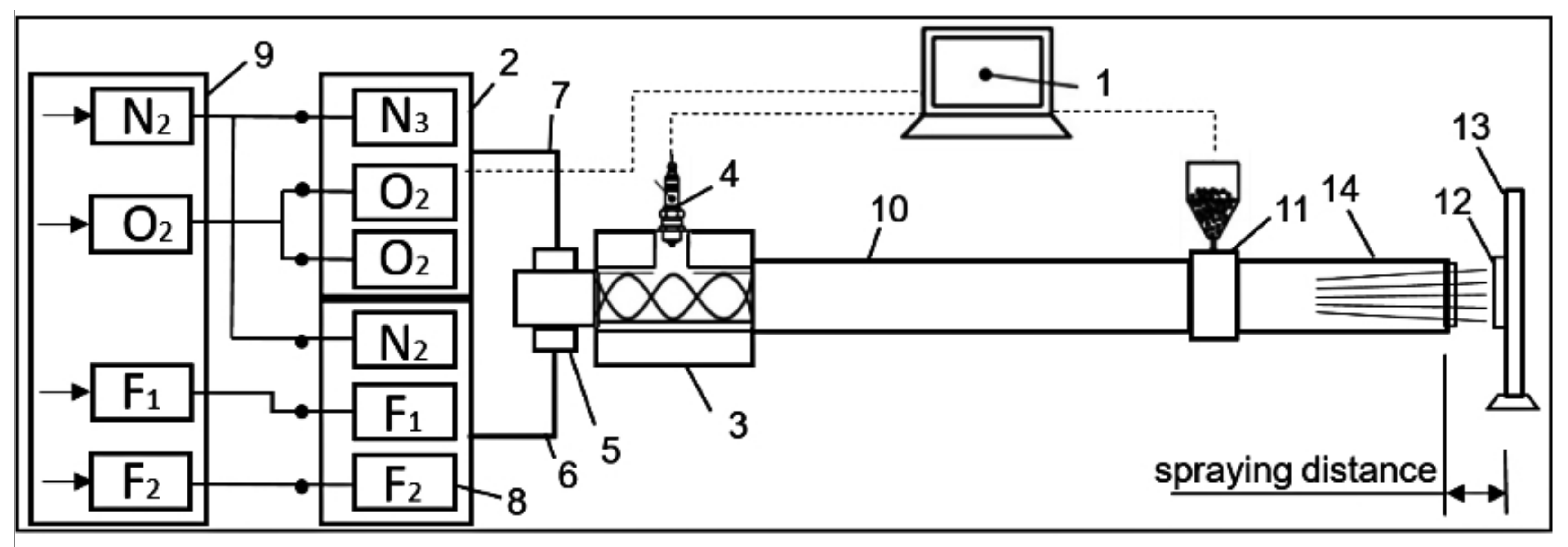
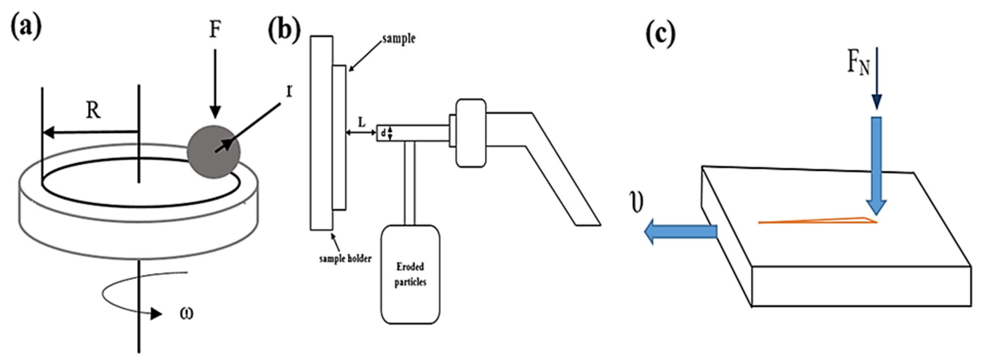
2. Materials and Methods

Al2O3 powder with a fineness of 50–65 μm was used as a sprayed material (INOX, LLC STC, Novosibirsk, Russia). Coatings were applied to 12Kh1MF steel samples by detonation spraying on CCDS2000 detonation unit (Computer-Controlled Detonation Spraying) (LIH SB RAS, Novosibirsk, Russia). Figure 1 [23] shows a schematic diagram of the CCDS2000 detonation complex. The coating is applied with a detonation gun, the barrel of which is filled with an explosive gas mixture, a metered portion of powder is thrown into the barrel and detonation is initiated by an electric spark. The detonation products heat the powder particles to melting point and throw them at high speed onto the part installed in front of the gun barrel. Upon collision, microwelding occurs, and the powder is firmly (at the molecular level) bonded to the surface of the part. After each shot, the barrel is purged with nitrogen to remove detonation residues. The required thickness is increased by successive series of shots, during which the object can be moved using a manipulator [25,26]. To obtain a coating based on Al2O3, industrial gases were used as a combustible gas: oxygen, acetylene, and propane–butane (component ratio 50/50, equivalent formula C3.5H9). The fuel/oxidizer ratio in the gas distributor was 1.856 (without using propane–butane) and 1.026 (using propane–butane). Spraying modes are shown in Table 1.
After X-ray phase studies of the samples were performed by X-ray diffraction analysis on an X’PertPRO diffractometer (Philips Corporation, Amsterdam, The Netherlands), diffraction patterns were recorded using CuKα radiation (λ = 2.2897 Å) at a voltage of 40 kV and a current of 30 mA. Diffraction patterns were decoded using the HighScore software. The microhardness of the cross section of the samples was measured by the Vickers method in accordance with GOST 9450–76 (ASTM E384-11) on a Metolab 502 micrometer (Metolab, Moskow, Russia) at an indenter load of P = 1 N and a holding time of 10 s. Micrographs of the coating surface were obtained using a metallographic microscope (Altami MET 5C, Altami LLC, Saint Petersburg, Russia). The roughness of the coatings surface Ra was estimated using a profilometer model 130 (Plant PROTON, Joint Stock Company, Moscow, Russia). As the main parameter for evaluating the surface roughness of the coating, the value of Ra was chosen, which is the arithmetic mean deviation of the profile.
Tribological tests for sliding friction were carried out on a TRB3 tribometer (Anton Paar Srl, Peseux, Switzerland) using the standard ball-disk technique (international standards ASTM G 133-95 and ASTM G99). The experimental setup is shown in Figure 2a. A ball with a diameter of 3.0 mm made of steel coated with SiC was used as a counterbody at a load of 5 N and a linear velocity of 15 cm/s; the radius of the wear curvature was 5 mm and the friction path was 50 m. The values for calculating the volumes of wear of the obtained coatings were established.
Erosion tests at room temperature were carried out on a special stand in accordance with ASTM G76-04 (Figure 2b). The test used a tube nozzle with a diameter of 3 mm, located at a distance of 15 mm from the sample; the angle of inclination of the nozzle in relation to the sample was 90°. The tests were carried out using a quartz abrasive with a grain diameter of 50 μm. The test duration was 3 min.
The CSEM Micro Scratch Tester (CSM, Neuchâtel, Switzerland) was used to test the adhesion characteristics of coatings by the “scratch” method (Figure 2c). Scratch testing was carried out at a maximum load of 30 N, the rate of change in the normal load on the sample was 29.99 N/min, the speed of the indenter was 6.794 mm/min, the length of the scratch was 7 mm, and the radius of curvature of the tip was 100 μm. To obtain reliable results, three scratches were applied to the surface of each coated sample.

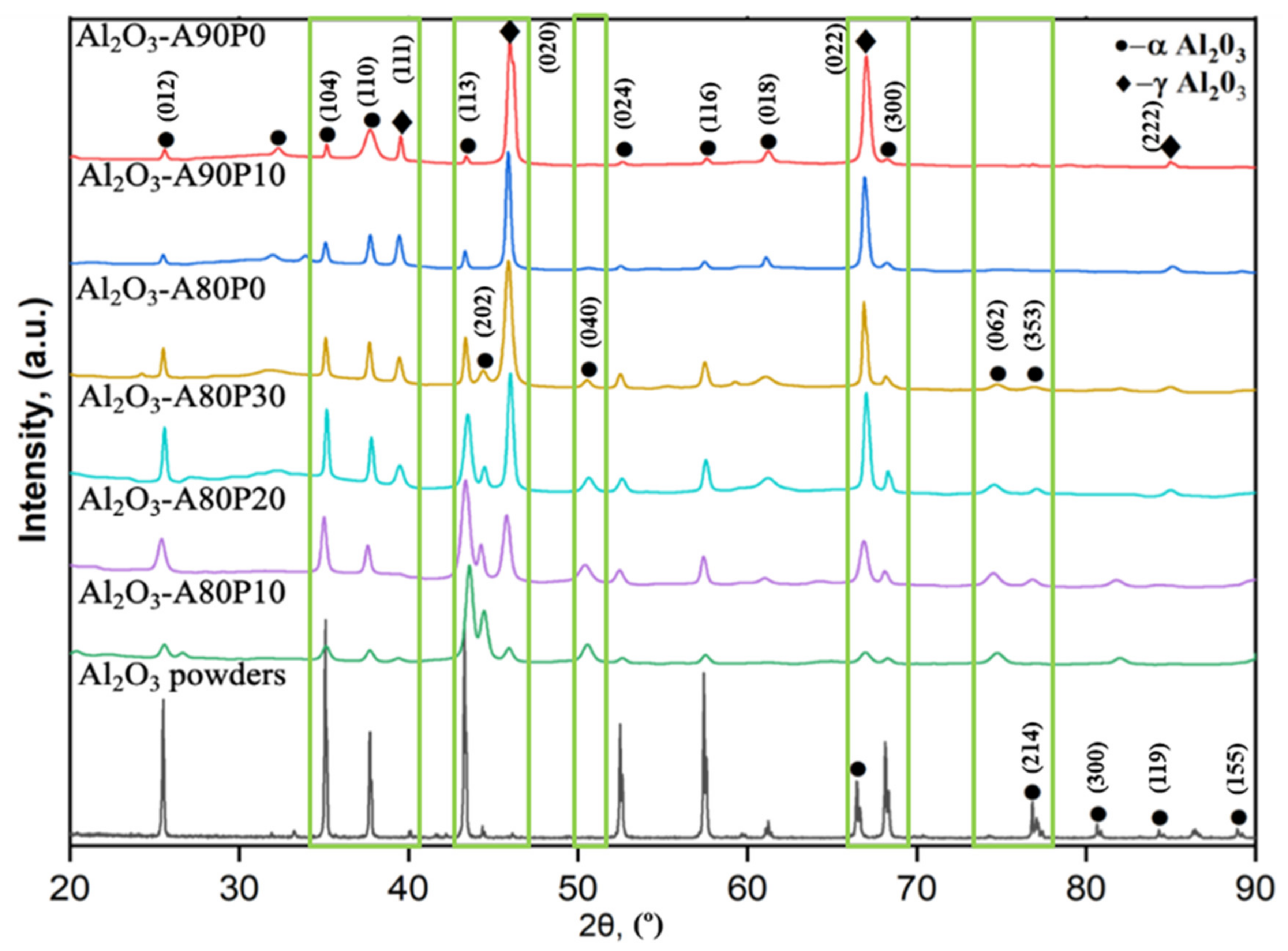
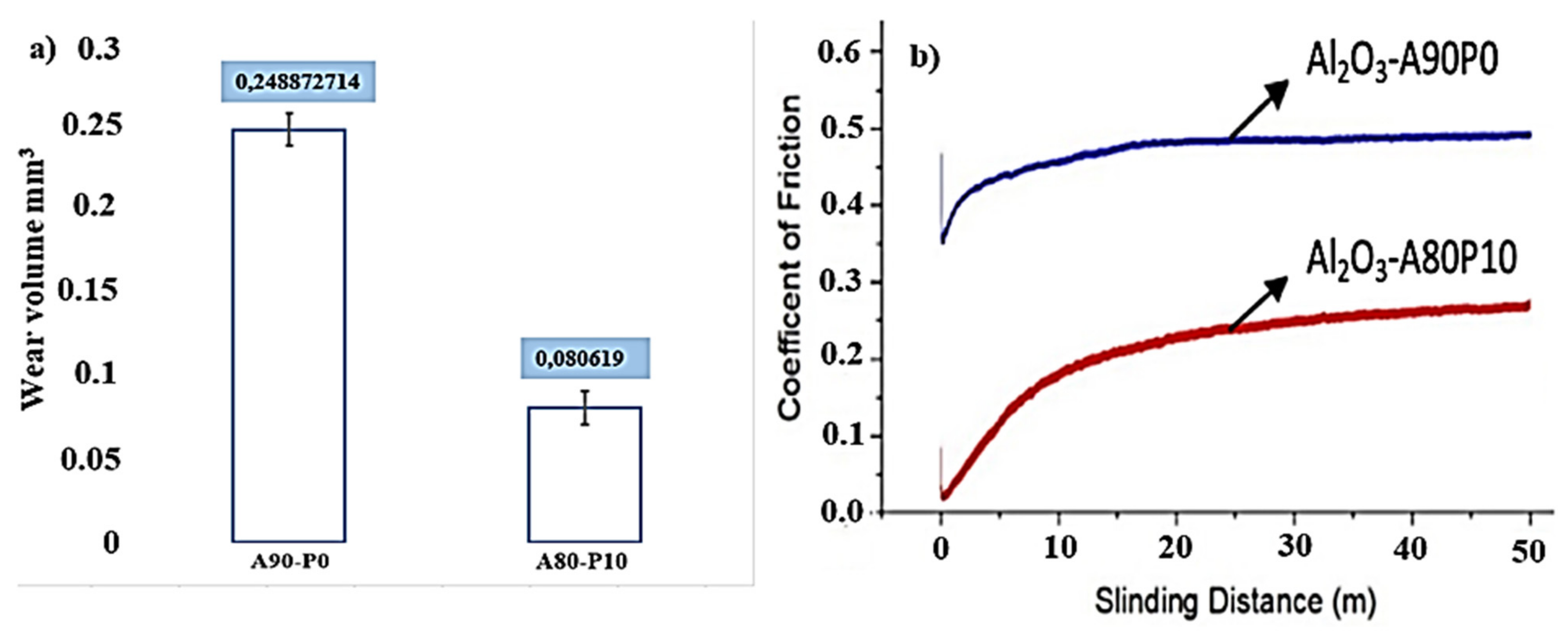
3. Results and Discussion

Under standard modes of detonation spraying using the initial powder of α-Al2O3, the resulting coatings have the main phase γ-Al2O3. In order to obtain coatings having the main phase of α-Al2O3, we carried out a series of experiments in various modes of detonation spraying. Al2O3 coatings were obtained by varying combustible gases. Figure 3 shows the diffraction patterns of the obtained coatings. The results of X-ray structural analysis of coatings showed that all coatings consist of γ-Al2O3 and α-Al2O3 phases. The results showed that despite the fact that the initial powder was from α-Al2O3, γ-Al2O3 phases were formed after spraying using an acetylene-oxygen mixture. This is explained by the fact that nonequilibrium recrystallization of α-Al2O3 to γ-Al2O3 occurs under shock wave conditions and rapid cooling during the formation of coatings. The diffraction peaks at 25.5°, 35.1°, 60.0°, 43.3°, 44.2°, 52.5°, 57.4°, 61.1°, 68.1°, 80.6° and 88.9° relate to ICDD card number 96-500-0093, and the diffraction peaks at 31. 9°, 37.7°, 39.4°, 50.2°, 66.8° and 84.9° relate to ICDD card number 96-500-0093, and the diffraction peaks at 45.8°, 76.1° and 79.4° relate to ICDD card number 96-500-0093.
Figure 3 shows that when propane is added to the oxygen–acetylene mixture, an increase in the interference lines of the α-Al2O3 phase is observed, i.e., an increase in the volume fraction of the α-Al2O3 phase. However, during a significant increase in the propane content, a decrease in the α-Al2O3 phase volume fraction can be observed. In samples A80-P20 and A80-P10, coatings are formed with the main content of the α-Al2O3 phase. A further decrease in the content of the acetylene–oxygen mixture or propane leads to a decrease in the quality of the coatings due to the presence of unmelted powder particles in it. Moreover, such weak spraying modes of Al2O3 powders are usually used for sandblasting the substrate surface before coating.
Thus, for the first time experimentally we obtained an aluminum oxide coating having the main phase of α-Al2O3 by detonation spraying method. Next, we carried out comparative studies of the structure, composition and properties of two coatings with the main phases of α-Al2O3 and γ-Al2O3. Two samples were studied: (1) A90-P0 sample coated with the main phase γ-Al2O3, obtained using a combustible gas consisting of an acetylene-oxygen mixture, (2) A80-P10 sample coated with the main phase α-Al2O3, obtained with using a combustible gas consisting of a propane-acetylene-oxygen mixture.
Tribological parameters are one of the main properties responsible for the durability of products. This work was evaluated by the wear volume value of coatings when tested according to the “ball-disc” scheme (Figure 4a). Figure 4 shows the data on the amount of wear (Figure 4a) and the coefficient of friction (Figure 4b) for samples A90-P0 and A80-P10. The test results showed that the A80-P10 sample has a low wear volume value compared to A90-P0. Figure 4b shows that the friction coefficient of the A90-P0 sample is 0.48, and the friction coefficient of the A80-P10 sample is 0.26. Thus, it can be stated that under the test conditions, the wear resistance of the A80-P10 sample is 2 times higher than that of the A90-P0. This is primarily due to an increase in the proportion of the α-Al2O3 phase in the A80-P10 coating, which has a high wear resistance.
Figure 5 shows the microstructure of the coatings and the results of measuring the surface roughness of the coating material based on Al2O3. Metallographic analysis showed that the coatings have an inhomogeneous structure with the presence of small pores. At the same time, the size and number of pores in the A90-P0 coating are larger than in the A80-P10 coating. The roughness parameter of the A80-P10 coating has a value of Ra = 1.72 (Figure 5a), and the A90-P0 coating has a value of Ra = 3.85 (Figure 5b), that is, the coating with the main phase of γ-Al2O3 has a higher roughness and porosity than the coating with the main phase of α-Al2O3. The high roughness and porosity of the A90-P0 coating is due to the difference in the effect of the shock wave and the resulting compaction of the coating.
Figure 6 shows a graph of the distribution of microhardness over the thickness of A90-P0 and A80-P10 coatings. The microhardness of the A80-P10 coating material is quite high compared to the A90-P0 coating. The high hardness of the A80-P10 coating is due to the fact that the main phase in it is α-Al2O3. The α-Al2O3 modification has a higher hardness and wear resistance compared to the γ-Al2O3 modification [25,26]. This confirms the results of X-ray diffraction analysis in which it is shown that the sample A80-P10 has a more significant proportion of α-Al2O3 than the sample A90-P0.
The results of erosion resistance tests showed that the A80-P10 coating is more resistant to erosion than the A90-P0 coating. Erosion craters on the surface of A90-P0 and A80-P10 coatings are shown in Figure 7. The calculated relative weight loss was 0.0773 g and 0.0953 g for A80-P10 and A90-P0 coatings, respectively. This can also be associated with an increase in the proportion of the α-Al2O3 phase, which is highly resistant to wear and erosion.
Figure 8 shows the SEM image of the cross-section of the coating A90-P0 (a) and A 80P10 (b). The coating thickness is ~100–120 μm. As can be seen in the figure, both coatings have a homogeneous layered structure characterized by a detonation coating.
One of the main factors determining the quality of the coating is adhesion. Figure 9 shows the results of the adhesion test for the scratch test. To determine the adhesive strength of the coatings, the coating surface was scratched with a Rockwell diamond indenter under a continuously increasing load (Figure 2b). During the tests, physical parameters were measured at various applied loads (Fn) and the scratch length. The moment of adhesive or cohesive destruction of the coating was recorded after testing using an optical microscope with a digital camera, as well as by changing two parameters: acoustic emission and friction force. Note that not all recorded coating failures describe the actual adhesion of the coating to the substrate. Various registration parameters during the tests made it possible to record different stages of the destruction of the coating. In particular, Fn is the load, AE is the acoustic emission, Ft is the frictional force, Lc1 is the critical load necessary for the origin of the first crack, Lc2 is the critical load that ensures the peeling of the coating areas and Lc3 is the binding load corresponding to the plastic abrasion of the coating on the surface [17]. By the type of change in the amplitude of acoustic emission (AE), one can judge the intensity of the formation of cracks and their development in the sample during scratching. In the A90-P0 coating, the first crack was formed at a load of Lc1 = 6 N (Figure 9a). Then, the process continued in a certain cycle. The corresponding acoustic emission peak accompanied the formation of each crack (Figure 9a). Partial abrasion of the coating on the substrate was judged by a sharp change in the intensity of the growth of the friction force; this happened at the load of Lc3 = 29 N. In the A80-P10 coating, the first crack formed at the load of Lc1 = 15 N (Figure 9b). According to the results of adhesion tests, it can be stated that the cohesive failure of the sample coating occurred at 15 N, and its adhesion failure at 29 N. The A90-P0 coatings have better adhesion strength than the A80-P10 coatings. This is due to the fact that the A90-P0 coating has γ-Al2O3 as the main phase, which is relatively more viscous than α-Al2O3, and this provides good adhesion of the coating to the substrate. Furthermore, Figure 9 shows microscopic images of the surface at different critical loads (Fn). Considering that the high exploitation resistance of the coatings is provided due to the high wear resistance and adhesive strength, it can be assumed that the layered coatings having a lower layer of γ-Al2O3 and an upper layer of α-Al2O3 makes it possible to obtain high-quality coatings based on aluminum oxide. In addition, as the results showed, the detonation technology makes it possible to adjust the phase composition of the coatings from γ-Al2O3 to α-Al2O3, then the detonation technology must be developed in the direction of obtaining functional-gradient coatings. As modern detonation devices of the CCDS2000 type, it allows automatic variation of technological modes during the spraying process.

4. Conclusions

Based on the results obtained, it was revealed that, depending on the composition and degree of filling of combustible mixtures, the phase composition of coatings based on aluminum oxide changes, that the composition of the coatings can vary from γ-Al2O3 to α-Al2O3. For the first time, an aluminium oxide coating with an alpha-Al2O3 out-of-body phase was obtained experimentally by detonation spraying.
The roughness measurements showed that the coating with the main phase γ-Al2O3 has a higher roughness than the coating with the main phase α-Al2O3.
Scanning electron microscope images showed that both coatings have a homogeneous layered structure characteristic of detonation coatings.
It was determined that the coating having the main phase of α-Al2O3 has high hardness, wear resistance and resistance to erosion in comparison with the coating having the main phase of γ-Al2O3.
It has been determined that the coating with γ-Al2O3 phase has a high adhesive strength compared to a coating with α-Al2O3 phase.
Thus, the results showed that it is possible to control the phase composition of coatings based on Al2O3 and, accordingly, the properties of coatings by changing the composition and degree of filling of combustible mixtures. The results obtained in the long-term make it possible to obtain layered or gradient coatings, which consist of a lower layer with the main phase γ-Al2O3, an upper layer with the main phase of α-Al2O3 and an intermediate layer consisting of α-Al2O3 and α-Al2O3. The production of such coatings provides high tribological and mechanical properties of the coatings, as the more viscous γ-Al2O3 phase provides good adhesion strength of the coatings to the substrate, and the α-Al2O3 phase, which is present in a large amount on the coating surface, provides high hardness and wear resistance. In future works, we will present the results on obtaining a gradient coating from alumina based on these results.

Author Contributions

B.R., G.M., S.P. and D.K. designed the experiments; L.Z., D.K. and D.B. performed the experiments; B.R. analyzed the data; B.R. and D.K. wrote, reviewed and edited the paper. All authors have read and agreed to the published version of the manuscript.

Funding

This research has been funded by the Science Committee of the Ministry of Education and Science of the Republic of Kazakhstan (Grant No. AP09058615).

Institutional Review Board Statement

Not applicable.

Informed Consent Statement

Not applicable.

Data Availability Statement

Data are contained within the article.

Conflicts of Interest

The authors declare no conflict of interest.

References

  1. Dhakar, B.; Chatterjee, S.; Sabiruddin, K. Measuring mechanical properties of plasma sprayed alumina coatings by nanoindentation technique. Mater. Sci. Technol. 2017, 33, 285–293. [Google Scholar] [CrossRef]
  2. Murray, J.W.; Ang, A.S.M.; Pala, Z.; Shaw, E.C.; Hussain, T. Suspension high velocity oxy-fuel (SHVOF)-sprayed alumina coatings: Microstructure, nanoindentation and wear. J. Therm. Spray Technol. 2016, 25, 1700–1710. [Google Scholar] [CrossRef]
  3. Nofz, M.; Dörfel, I.; Sojref, R.; Wollschläger, N.; Mosquera-Feijoo, M.; Kranzmann, A. Microstructure, smoothening effect, and local defects of alumina sol-gel coatings on ground steel. J Sol-Gel. Sci. Technol. 2017, 81, 185–194. [Google Scholar] [CrossRef]
  4. Shen, Y.; Tao, H.; Lin, Y.; Zeng, X.; Wang, T.; Tao, J.; Pan, L. Fabrication and wear resistance of TiO2/Al2O3 coatings by micro-arc xidation. Rare Metal Mat. Eng. 2017, 46, 23–27. [Google Scholar]
  5. Wang, Y.L.; Wang, M.; Zhou, M.; Li, B.J.; Amoako, G.; Jiang, Z.H. Microstructure characterisation of alumina coating on steel by PEO. Surf. Eng. 2013, 29, 271–275. [Google Scholar] [CrossRef]
  6. Rafailovit, L.D.; Gammer, C.; Rentenberger, C.; Tomislav, T.; Christoph, K.; Hans, P. Functionalizing aluminum oxide by Ag dendrite deposition at the anode during simultaneous electrochemical oxidation of Al. J. Adv. Mater. 2015, 27, 6438–6443. [Google Scholar] [CrossRef]
  7. Masuda, H.; Yamada, H.; Satoh, M.; Asoh, H.; Tamamura, T. Highly ordered nanochannel-array architecture in anodic alumina. Appl. Phys. Lett. 1997, 71, 2770–2772. [Google Scholar] [CrossRef]
  8. Singh, I.B.; Modi, O.P.; Ruhi, G. Development of sol–gel alumina coating on 9Cr–1Mo ferritic steel and their oxidation behavior at high temperature. J. Sol-Gel. Sci. Technol. 2015, 74, 685–691. [Google Scholar] [CrossRef]
  9. Wollschläger, N.; Nofz, M.; Dörfel, I.; Schulz, W.; Sojref, R.; Kranzmann, A. Exposition of sol-gel alumina-coated P92 steel to flue gas: Time-resolved microstructure evolution, defect tolerance, and repairing of the coating. Mater. Corros. 2017, 69, 1–11. [Google Scholar] [CrossRef]
  10. Djendel, M.; Allaoui, O.; Boubaaya, R. Characterization of alumina-titania coatings produced by atmospheric plasma spraying on 304 SS steel. Acta Phys. Pol. 2017, 132, 538–540. [Google Scholar] [CrossRef]
  11. Yin, Z.; Tao, S.; Zhou, X.; Ding, C. Tribological properties of plasma sprayed Al/Al2O3 composite coatings. Wear 2007, 263, 1430–1437. [Google Scholar] [CrossRef]
  12. Li, C.; Zou, J.; Huo, H.B. Microstructure and properties of porous abradable alumina coatings flame-sprayed with semi-molten particles. J. Therm. Spray Technol. 2016, 25, 264–272. [Google Scholar] [CrossRef]
  13. Jia, S.; Zou, Y.; Xu, J. Effect of TiO2 content on properties of Al2O3 thermal barrier coatings by plasma spraying. Trans. Nonferrous Met. Soc. China 2015, 25, 175–183. [Google Scholar] [CrossRef]
  14. Ulianitsky, V.Y.; Shtertser, A.A.; Batraev, I.S.; Rybin, D.K. Fabrication of layered ceramic-metal composites by detonation spraying. Ceram. Int. 2020, 46, 27903–27908. [Google Scholar] [CrossRef]
  15. Ulianitsky, V.; Shtertser, A.; Zlobin, S.; Smurov, I. Computer-controlled detonation spraying: From process fundamentals toward advanced applications. J. Therm. Spray Technol. 2011, 20, 791–801. [Google Scholar] [CrossRef]
  16. Zywitzki, O.; Hoetzsch, G. Effect of plasma activation on the phase transformations of aluminum oxide. Surface Coat. Technol. 1995, 76–77, 754–762. [Google Scholar] [CrossRef]
  17. Lin, H.C.; Ye, P.D.; Wilk, G.D. Leakage current and breakdown electric-field studies on ultrathin atomic-layer-deposited Al2O3 on GaAs. Appl. Phys. Lett. 2005, 87, 182904–182906. [Google Scholar] [CrossRef]
  18. Sabiruddin, K.; Joardar, J.; Bandyopadhyay, P.P. Analysis of phase transformation in plasma sprayed alumina coatings using rietveld refinement. Surf. Coat. Technol. 2010, 204, 3248–3253. [Google Scholar] [CrossRef]
  19. Vardelle, A.; Vardelle, M.; Fauchais, P. Influence of velocity and surface temperature of alumina particles on the properties of plasma sprayed coatings. Plasma Chem. Plasma Process. 1982, 2, 255–291. [Google Scholar] [CrossRef]
  20. Niu, B.; Qiang, L.; Zhang, J.; Zhang, F.; Hu, Y.; Chen, W.; Liang, A. Plasma sprayed α- Al2O3 main phase coating using γ-Al2O3 powders. Surface Eng. 2019, 35, 801–808. [Google Scholar] [CrossRef]
  21. Qiang, L.; Zhang, X.; Ai, Y.; Zhang, Z.; Zhuang, Y.; Sheng, J.; Ni, J.; Yang, K. In-situ Deposition of Novel Amorphous Al2O3-Gap Ceramic Coating with Excellent Microstructure Stability and Uniformity via Atmospheric Plasma Spraying. iScience 2021, 35. [Google Scholar]
  22. Rakhadilov, B.K.; Buytkenov, D.B.; Kakimzhanov, D.; Kozhanova, R.S.; Bektasova, G.S. The effect of detonation spraying on the phase composition and hardness of Al2O3 coatings. Eurasian J. Phys. Funct. Mater. 2020, 4, 160–166. [Google Scholar] [CrossRef]
  23. Rakhadilov, B.K.; Buitkenov, D.B.; Rakhadilov, M.K. Tribological Properties of Al2O3 Coatings Obtained by Detonation. IOP Conf. Ser. Mater. Sci. Eng. 2021, 1079, 052035. [Google Scholar] [CrossRef]
  24. Kantay, N.; Rakhadilov, B.; Kurbanbekov, S.; Yerbolatova, G.; Apsezhanova, A. Influence detonation-spraying parameters on the phase composition and hardness of Al2O3 coating. Coatings 2021, 11, 793. [Google Scholar] [CrossRef]
  25. Ulianitsky, V.Y.; Dudina, D.V.; Shtertser, A.; Smurov, I. Computer-controlled detonation spraying: Flexible control of the coating chemistry and microstructure. Metals 2019, 12, 1244. [Google Scholar] [CrossRef] [Green Version]
  26. Rakhadilov, B.; Buitkenov, D.; Sagdoldina, Z.; Kurbanbekov, S.; Adilkanova, M. Structural Features and Tribological Properties of Detonation Gun Sprayed Ti–Si–C Coating. Coatings 2021, 11, 141. [Google Scholar] [CrossRef]
Figure 1. Schematic diagram of the computer-controlled detonation spraying setup CCDS2000: 1—control computer; 2—gas distributor; 3—mixing ignition chamber; 4—spark plug; 5—barrel valve; 6—fuel line; 7—oxygen line; 8—gas valves; 9—gas supply unit; 10—indicated part of the barrel; 11—powder feeder; 12—workpiece; 13—manipulator; 14—the muzzle of the barrel; F1—acetylene; F2—propane–butane; O2—oxygen; N2—nitrogen. Reprinted from Ref. [23].
Coatings 11 01566 g001
Figure 2. Scheme of testing the coatings for wear resistance (a), erosion resistance (b) and adhesive strength (c).
Coatings 11 01566 g002
Figure 3. Diffraction patterns of Al2O3 coatings obtained under different modes of detonation spraying.
Coatings 11 01566 g003
Figure 4. The wear volume (a) and the coefficient (b) of A90-P0 and A80-P10 coatings.
Coatings 11 01566 g004
Figure 5. Relief and surface roughness micrographs of A80-P10 (a) and A90-P0 (b) coatings.
Coatings 11 01566 g005
Figure 6. Distribution of hardness graph by depth of A90-P0 (a) and A80-P10 (b) coatings.
Coatings 11 01566 g006
Figure 7. Comparison of erosion craters of A90-P0 (a) and A80-P10 (b) coatings after testing for resistance to erosion.
Coatings 11 01566 g007
Figure 8. SEM image of the cross section of the coating A90-P0 (a) and A 80P10 (b).
Coatings 11 01566 g008
Figure 9. Scratch test results of the A90-P0 (a) and A80-P10 (b) coatings.
Coatings 11 01566 g009
Table 1. Technological modes of spraying coatings from aluminum oxide.
SampleFilling the Barrel with Gas Fuel C2H2/C3H8Fuel/Oxidizer RatioBarrel Filling Volume, %Spray Distance, mmNumber of Shots
Al2O3-A80P1080/101.0265625020
Al2O3-A80P2080/201.0265725020
Al2O3-A80P3080/301.0265925020
Al2O3-A80P080/01.8565525020
Al2O3-A90P1090/101.0266425020
Al2O3-A90P090/01.8566325020
Publisher’s Note: MDPI stays neutral with regard to jurisdictional claims in published maps and institutional affiliations.

