Article

Oxidation Behavior and Microstructural Evolution of ZrB2–35MoSi2–10Al Composite Coating

1
Joint Research Center “Technology and Materials”, Belgorod State National Research University, 308015 Belgorod, Russia
2
Center for High Technologies, Belgorod State Technological University Named after V.G., 308012 Belgorod, Russia
3
E.O. Paton Electric Welding Institute, NASU, 03650 Kyiv, Ukraine
*
Author to whom correspondence should be addressed.
Coatings 2021, 11(12), 1531; https://doi.org/10.3390/coatings11121531
Submission received: 11 November 2021 / Revised: 1 December 2021 / Accepted: 8 December 2021 / Published: 13 December 2021

Abstract

:
The problem of creating and implementing high-temperature coatings for the protection of carbon–carbon (C/C) composites remains relevant due to the extremely low or insufficient heat resistance of C/C composites in an oxygen-containing environment. In the present work, detonation spraying was used for preparing new ZrB2–35MoSi2–10Al coatings on the surface of C/C composites without a sublayer. As a stabilizer of high-temperature modification of zirconia, and to increase the wettability of the surface of C/C composites, 5 wt.% Y2O3 and 10 wt.% Al were added to the initial powder mixture, respectively. The structure of the as-sprayed coating presents many lamellae piled up one upon another, and is composed of hexagonal ZrB2 (h- ZrB2), tetragonal MoSi2 (t-MoSi2), monoclinic ZrO2 (m-ZrO2), tetragonal ZrO2 (t-ZrO2), monoclinic SiO2 (m-SiO2), and cubic Al phases. The oxidation behavior and microstructural evolution of the ZrB2–35MoSi2–10Al composite coating were characterized from RT to 1400 °C in open air. During oxidation at 1400 °C, a continuous layer of silicate glass was formed on the coating surface. This layer contained cubic ZrO2 (c-ZrO2), m-ZrO2, and small amounts of mullite and zircon. The results indicated that a new ZrB2–35MoSi2–10Al composite coating could be used on the surface of C/C composites as a protective layer from oxidation at elevated temperatures.

1. Introduction

Recently, carbon–carbon (C/C) composites have attracted great attention from researchers [1]. The advantages of C/C composites include low density (1.3–2.1 t/m3); high heat capacity; resistance to thermal shock, erosion, and radiation; low coefficients of friction and linear expansion; and high strength and rigidity [2]. However, the use of C/C composites is significantly constrained by their extremely low or insufficient heat resistance in oxygen-containing environments [3]. Gas corrosion of most C/C composites begins at a temperature of 400–500 °C, and is accompanied by the formation of volatile oxides such as CO (mainly) and CO2, while at temperatures above 1300 °C it becomes catastrophic, until their complete burnout [4]. Their use is possible only with protective, heat-resistant, gas-tight coatings, which prevent the access of oxygen to carbon [5].
Single-layer, multi-layer, and composite heat-resistant coatings are formed as protective coatings on the surface of carbon–carbon composites [6,7,8]. Oxide–intermetallic and metal–ceramic coatings are used as single-layer protective coatings on carbon–carbon composites [6,9]. However, pure oxide coatings are not promising for the protection of carbon–carbon composites, due to the high brittleness of the oxides and significant differences in the thermophysical characteristics of the base and coating materials. Therefore, refractory oxides are mainly used as an integral part of complex multilayer and composite heat-resistant coatings [10]. Various intermetallic and metal–ceramic oxygen-free compounds and their compositions are most widely used in the creation of single-layer protective coatings on carbon–carbon composites [6,11]. As the main structural components, refractory aluminides, borides, silicides, carbides, or their alloys are used, which are capable of forming protective oxide films on the surface during oxidation.
In general, single-layer coatings are incapable of achieving the numerous requirements for the surface of structural materials [12,13]. Therefore, recently, much attention has been paid to the development of more complex multilayer and composite protective coatings [12,14,15,16,17,18].
One of the most common approaches to choosing the composition of the main layer of a high-temperature coating is the selection of the composition of refractory compounds that are in a viscoplastic state during the operation of the product. This state is achieved by using refractory boron or aluminoborosilicate glasses as a matrix, in which the reinforcing particles—silicides, carbides, and borides (less often oxides and nitrides)—of metals of groups IV–VI are additionally introduced to increase heat resistance [15,16,17,18].
The use of ZrB2-based systems is promising for this class of oxidation resistance coatings; these have been widely researched in recent years, owing to their high melting point, high thermal conductivity, low density, and high strength at ultrahigh temperatures [19,20,21]. However, it is challenging to achieve densification using ZrB2 due to its strong covalent bond and low diffusion coefficient [22], which also becomes porous during the oxidation process [21]. Molybdenum disilicide has effective resistance at temperatures of 1000–1700 °C, due to the formation of a protective layer based on silicon dioxide [23]. The introduction of MoSi2 into ZrB2–MoSi2 coatings increases the compactness of ZrB2 and effectively reduces the oxidation consumption of ZrB2 [23,24]. Coatings of the ZrB2–MoSi2 system are obtained via electrolytic and electrophoretic deposition from solutions [25], pack cementation [17,26], slurry methods [17,27,28,29], plasma spraying [30,31], etc. All of these methods require special preliminary surface preparation or the formation of a bonding sublayer between the coating material and the substrate [17,25,26,27,28,29].
Thermal spraying is a highly efficient method to deposit coatings [32,33,34,35,36]. The use of high-speed gas–thermal methods, which impart high kinetic energy to powder particles while reducing their temperature, is expedient for obtaining coatings on the carbon–carbon materials’ surface. The technology of detonation spraying of industrial coatings is characterized by economy and environmental friendliness, since the plasma components used are not hostile substances to the environment. In addition, there is no need to apply preliminary surface preparation and use energy-intensive vacuum, heating, and cooling equipment (as in the case of traditional laser, electron beam, and vacuum plasma technologies) [32,33,34,35,36]. However, the sprayed coatings exhibit a porous structure, which cannot create an effective barrier against the corrosive environment for substrates [32,37].
In connection with the above, the purpose of this work is to show the effectiveness of a robotic complex for the detonation spraying of coatings (IntelMashin LLC., Moscow, Russia), equipped with a multi-chamber detonation accelerator for obtaining original composite ZrB2–35MoSi2–10Al coating on carbon–carbon composites via oxidation at elevated temperatures. A total of 5 wt.% Y2O3 was added to the initial powder mixture as a stabilizer of high-temperature tetragonal and cubic modification of zirconia [31,38]. Coatings of the ZrB2–MoSi2 system were formed on the surface of carbon–carbon composites without intermediate layers to perform barrier-compensation functions. To increase the wettability of the surface of C/C composites, and to increase the diffusion reaction between Si and C, Al powder was added to the initial powder mixture [38]. In the present work, the microstructural evolution and phase transformation in the ZrB2–35MoSi2–10Al coating during annealing treatment from room temperature to 1400 °C were investigated.

2. Materials and Methods

ZrB2, MoSi2, Y2O3, and Al micropowders (Russia) were used for applying composite coatings. The powders were sieved and the working fractions (<20 microns) were selected. Then, to obtain the composite powder ZrB2 + 35MoSi2 + 5wt.%Y2O3 + 10Al (denoted as ZrB2–35MoSi2–10Al), mechanical mixing and homogenization of the initial powders was carried out in a Pulverisette 5 laboratory planetary mill (Fritsch, Idar-Oberstein, Germany) with balls and grinding glasses made of zirconium oxide in alcohol for 24 h, at a drum rotation speed of 150 rpm (Figure 1a). Then, the charge was removed from the grinding glasses, dried in a drying cabinet (100 °C, 6 h), and wiped through a sieve. All of the operations were performed in the air.
Figure 1b shows the X-ray diffraction (XRD, (Rigaku, Tokyo, Japan) of the composite powder. The ZrB2–35MoSi2–10Al powder consisted of hexagonal ZrB2 (h-ZrB2), tetragonal MoSi2 (t-MoSi2), and cubic Y2O3 (c-Y2O3) and Al phases (Figure 1b). Flat specimens (10 × 10 × 5 mm3) of 3D C/C composites (density of 1.9 g/cm3) were used as substrates. The specimens for thermogravimetric tests were cubic (5 × 5 × 5 mm3). ZrB2–35MoSi2–10Al coating was obtained on the surface of C/C composites using a robotic complex for detonation spraying of coatings (IntelMashin LLC, Russia) (Figure 2) equipped with a multi-chamber detonation accelerator (MCDS) [35,36,37,38,39,40].
The physical essence of the detonation coating technology using a multi-chamber detonation accelerator (MCDS, IntelMashin LLC, Moscow, Russia) is the collision of fine particles heated and accelerated in a supersonic flow of combustion products with a solid substrate. At the same time, according to the law of conservation of energy, the kinetic energy of the particle on impact turns into thermal energy. The process of a particle impacting on a solid substrate is carried out in 10−5–10−7 s. Consequently, a significant amount of power is concentrated on a small contact pad, which ensures the melting of the layer on the contact pads, the mixing of materials, and their chemical interaction. The MCDS provides a high speed of >1600 m/s, and a compact powder jet of up to 100 g/s, with a ceramic spraying capacity of up to 1 kg/h. Compact powder jets with a frequency of 20–50 Hz flow onto the surface of the product and carry out collective interaction. The high-energy front of the powder jet activates the surface layer of the material and ensures the chemical interaction of the subsequent dispersed particles with the coating material. The process of coating formation is carried out in layers, using the effects of collective interaction between the powder jet and the surface, which determines its high quality. The high speed of dispersed materials ensures their plastic deformation, nanostructuring, and the creation of thin lamellae (thickness of 4–8 microns). Heating and acceleration of a compact dose of powder are carried out by a controlled high-speed gas medium in a space limited by a solid wall, which allows each dispersed particle to be accelerated and heated equally [35,36]. The parameters of the coating spray are listed in Table 1.
The coating was formed on the substrate surface without the intermediate layers in the “carbon-containing materials–coating” system that perform barrier-compensation functions.
The specimens were transversally cut, mechanically polished, and prepared by standard metallographic methods—sectioning, mounting, and polishing—for sample preparation. The sample was prepared by grinding with SiC sandpaper of various specifications (200, 500, 800, and 1000#), followed by polishing with 1 μm diamond slurry in accordance with the procedure recommended by Struers for ceramic coatings. The specimens were cleaned with distilled water and dried at 100 °C for 3 h.
Porosity was determined via the metallographic method, with elements of the qualitative and quantitative analyses of the geometry of the pores using an optical inverted Olympus GX51 microscope (Olympus Corporation, Tokyo, Japan). The images were registered with an optic microscope in the bright field. The image acquisition of the structure of the studied layer was performed with the SIAMS Photolab software. At least 10 arbitrarily selected typical micrographs were analyzed for each experimental point.
The microstructure evolution and phase transformation in the coating during annealing treatment were investigated via scanning electron microscopy with energy-dispersive spectroscopy using a Nova NanoSEM 450 (SEM, FEI Company, Eindhoven, Netherlands) and a Rigaku Ultima IV powder X-ray diffractometer (Rigaku, Tokyo, Japan) with Cu-Kα radiation equipped with a high-temperature attachment—SHT-1500. A Rigaku SHT-1500 chamber (Rigaku, Tokyo, Japan) with a Pt sample holder (20 × 12 × 2 mm3) was used to collect the data for the ZrB2–35MoSi2–10Al coating in air within 25–1400 °C, at a heating rate of 10 °C/min. The sample was heated to the set temperature at a rate of 10 °C/min and then, in order to stabilize the temperature and the course of the processes, the system was thermostatted for 30 min. The analyzed range of the diffraction angle 2θ was from 20° to 80°, with a step width of 0.02°. The collection time at each temperature step was ~30 min. The phases were identified using the database of powder X-ray diffraction standard PDF-2. The program for air treatment of coating samples was formed considering the data obtained using the combined TA Instruments (TA Instruments, New Castle, DE, USA) SDT-Q600 (Simultaneous TGA/DSC (Figure 3a).

3. Results

Figure 4 shows the results of the study of the microstructure and phase composition of the as-sprayed ZrB2–35MoSi2–10Al coating. The surface of the ZrB2–35MoSi2–10Al coating is rough and composed of a fully molten area and an insufficiently molten area (Figure 4a). These molten phases make un-melted particles stick together. There are no voids in the insufficiently molten area. Uniform dense coating was obtained (Figure 4c–e). The structure of the coating presents many lamellae piled up one upon another. Microcracks caused by internal residual stresses during the spraying process were not observed. The porosity of the obtained coating was 0.02–1.00%.
The X-ray diffraction data of the coating are shown in Figure 4b. During the coating process, the initial components interact with atmospheric oxygen to form zirconium oxide (m-ZrO2 #01-088-2390 and t-ZrO2 #01-080-0784) and silicon oxide (m-SiO2 #01-072-1601) in small amounts (Figure 4b). No boron or molybdenum oxides were detected by XRD, due to their fairly low concentrations. The phase analysis of the coating showed that the coating also consists of the following phases: ZrB2 with a hexagonal crystal lattice (#03-065-8704), Al with a cubic crystal lattice (#03-065-2869), and MoSi2 with a tetragonal crystal lattice (#01-080-0544) (Figure 4b). Oxidation of initial reagents during deposition is a heterogeneous chemical process that occurs in the diffusion region for a very short time; therefore, when high temperatures are reached during deposition, complete oxidation of the initial substances does not occur.
The changes in the microstructure and phase composition of the coating after treatment in air at 1400 °C were observed (Figure 5). The coating after treatment is dense, with many white particles distributed in its matrix (Figure 5a,d,e). Through XRD (Figure 5c) and spot analyses of EDS (Figure 5e,f), the white particles were confirmed as ZrO2, and the light gray layer was confirmed as SiO2 glass with mullite, along with small amounts of zircon. The silicate glass layer can cover the defects and block the diffusion path of oxygen [41,42].
The microstructural evolution and phase transformation in the coating during annealing treatment from room temperature (~25 °C) to 1400 °C in normal atmosphere and pressure were also investigated. The TGA–DSC technique was employed to investigate and determine the precise onset temperature of phase transformations (Figure 3a). To understand the actual structural changes associated with the phase transformation reaction, XRD with in situ high-temperature experiments (HT–XRD) was also performed (Figure 3b,c).
The TGA shows that the thermal degradation process of the ZrB2-35MoSi2-10Al coating can be divided into three temperature stages: from room temperature to 450 ºC, 450–960 °C, and 960–1400 °C.
Below 350 °C, the first weight loss (0.3 wt%) was observed, corresponding to the loss of adsorbed water. Then, a constant increase in mass was observed, due to the oxidation of the starting materials.
The first exothermic effect on the DTA curve near 457 °C corresponds to the crystallization of the monoclinic phase of zirconium dioxide (m-ZrO2 #01-088-2390); a comparison of the XRD data of the as-sprayed coating and the coating treatment at 457 °C (Figure 3b and Figure 4b) confirms this. It is also confirmed by the increase in the relative intensity of the reflections corresponding to this phase (Figure 3b and Figure 4b). Other changes in the phase composition at 457 °C were not fixed.
The endothermic peak on the DTA curve with an extremum at 638 °C (Figure 3a) is due to the formation of the Al12Mo phase with a cubic crystal lattice (c-Al12Mo #03-065-1785). This is confirmed by a decrease in the intensity of the aluminum reflection (Figure 3b) and the formation of reflections corresponding to the c-Al12Mo phase.
According to the Al–Mo phase diagram [43,44] and the data given in [45], the formation of the Al12Mo phase is thermodynamically possible at a given temperature. Moreover, in [45], a method was proposed for producing the Al12Mo phase in situ during the annealing of a composite material based on the Al–MoSi2–ZrO2 system, in accordance with the following scheme:
12 Al l + Mo Si 2 s Al 12 Mo s + 2 Si O 2 s
The mechanism of the formation of Al12Mo considered in [45] assumes the dissolution of molybdenum from molybdenum disilicide in an aluminum melt, which is not consistent with the DTA data. The peak temperature (638 °C) is well below the melting point of aluminum (660 °C). However, in [46], the authors assume that the formation of phases similar to the Al12Mo phase is determined, first of all, by the kinetics of diffusion of aluminum atoms, due to their high mobility. Therefore, it can be assumed that at the moment of oxidation of MoSi2, nanosized reaction products are formed, which are capable of forming the Al12Mo phase through the interdiffusion of aluminum and molybdenum at the interface below the melting point of aluminum. Silicon, in accordance with Expression (1), is released in the form of silicon oxide (m-SiO2 #01-088-2390), as evidenced by the increase in the intensity of reflections corresponding to this phase with an increase in the annealing temperature (Figure 3b). Evaporation of molybdenum oxide at this temperature is not observed, which is confirmed by the weight gain on the TGA curve in the region of 638 °C. Complete destruction of molybdenum disilicide does not occur at any given temperature.
Furthermore, the annealing temperature was increased to 736 °C, in accordance with the TGA-DSC data (Figure 3a). The endothermic effect on the DTA curve at a given temperature is due to the oxidation of zirconium diboride. Despite the high melting point of ZrB2 (~3000 °C), the destruction of materials based on zirconium diboride begins at lower temperatures, due to the oxidation of the components with atmospheric oxygen.
Oxidation of materials based on ZrB2 at temperatures below ~1000–1200 °C (depending on the composition of the atmosphere and pressure) occurs according to the following reaction:
2 Zr B 2 s + 2.5 O 2 g Zr O 2 s + B 2 O 3 g
At temperatures above 450 °C, boron oxide is liquid, and due to the large contact angle on zirconium oxide it is distributed in the resulting pores, filling them and hindering further diffusion of oxygen into the interior of the material. An increase in temperature to ~1100 °C significantly reduces the protective properties of the liquid B2O3 layer, due to its active evaporation from the sample surface:
B 2 O 3 l = B 2 O 3 g
The formation of silicon oxide in the course of high-temperature oxidation, due to the oxidation of molybdenum disilicide by the following reaction:
2 Mo Si 2 s + 5.5 O 2 g Mo 2 O 3 g + 4 Si O 2 s
leads to the formation of a viscous borosilicate glass with a high boiling point.
This also makes it difficult to diffuse oxygen to the non-oxidized areas of the material. According to the Stokes–Einstein equation, the diffusion coefficient is inversely proportional to the viscosity of the medium in which the transport takes place. This significantly slows down the process of further oxidation, and also leads to suppression of the transition of B2O3 to the gas phase, due to a decrease in its activity in the SiO2–B2O3 system. This effect on the diffractogram manifests itself in the form of a decrease in the intensity of reflections of the corresponding h-ZrB2 (Figure 3b).
Temperature ~740 °C is also characterized by an increase in the intensity of reflections corresponding to m-SiO2.
The complete oxidation of the starting materials takes place with the annealing temperature above about 960 °C. At a temperature of ~960 °C in the coating mullite, a rhombic crystal lattice of isostructural mullite of the composition Al2.35Si0.64O4.82 begins to form in small amounts (Figure 3c). The main phases at this temperature are m-SiO2 and m-ZrO2. Furthermore, the zirconium orthosilicate phase (zircon–ZrSiO4 #01-081-0589) is formed in the coating. In accordance with the state diagram of the ZrO2–SiO2 system [47], in this temperature range, the formation of ZrSiO4 with an admixture of ZrO2 or SiO2 oxides is possible. In most of the works devoted to the synthesis of zircon (ZrSiO4), the production temperature is significantly higher than ~960 °C [48,49]. In [50] it was shown that the introduction of substances (MgO, CaO, Na2O) capable of forming an amorphous glass phase upon interaction with silicon dioxide into the system can lead to a significant decrease in the onset of the formation temperature of ZrSiO4. In this study, B2O3 could be such a substance.
At a temperature of ~1050 °C, the coating has the following composition: m-ZrO2, ZrSiO4, m-SiO2, and mullite (Figure 3c). The content of mullite, according to X-ray phase analysis, is close to the detection limit (the intensity of reflections corresponding to mullite is close to the background intensity).
The endothermic effect on the DTA curve at a temperature of ~1050 °C corresponds to the formation of ZrSiO4 (Figure 3c). The qualitative phase composition remains constant with an increase in temperature from ~960 to ~1050 °C, but the quantitative ratio of the phases changes (Figure 3c).
As can be seen from Figure 6, the coating becomes denser and more uniform during treatment at temperatures from ~460 to 1220 °C, and there is no mullite (the finest intertwined needle-shaped crystals penetrating the glass phase) in the structure of the coating. There are also no voids or cracks in the coating.
In the temperature range from 1220 to 1400°C, the DTA curve of ZrB2–MoSi2–Y2O3–Al coating (Figure 3a) shows a broad exothermic peak corresponding to the formation of mullite (r-Al2.35Si0.64O4.82 #01-073-1253) and the simultaneous destruction of zircon (t-ZrSiO4) (Figure 3c). Moreover, upon reaching the maximum temperature, cubic zirconia (c-ZrO2 #01-070-4436) is formed in the system (Figure 3c).
It was found that at a temperature of 1240 °C a two-phase material is formed in the coating, consisting of cubic zirconium dioxide and mullite (Figure 3c). The needle-shaped crystals of mullite are observed in the structure of the coating at a temperature of ~1240 °C (Figure 6).
The m-ZrO2 and t-ZrSiO4 phases are also retained in the coating, which can be explained by the insufficient time of the annealing process under the conditions of this analysis (Figure 3c).
Dissolving zirconium oxide in amorphous silica scale could enhance its oxidation resistance [51]. Zr-based oxides have high melting temperatures (ZrO2 – 2715 °C, ZrSiO4 – 2550 °C) and CTEs (ZrO2–10.5 × 10⁻⁶ °C−1, ZrSiO4–4.9 × 10⁻⁶ °C−1) in contrast with pure SiO2 (1650 °C and 0.55 × 10⁻⁶ °C−1). Therefore, their dispersion in glass could increase the melting temperature and the CTE of silica, which could minimize the difference in CTE between silica and MoSi2, reducing the internal stress of the coating [52].
The TGA curves show the onset of the weight loss effect (Figure 3a). This behavior of the TGA curve is most likely due to the evaporation of molybdenum oxide. The absence of reflections in the X-ray diffraction patterns of the corresponding MoO3 can be explained by the formation of a solid solution with the coating components. The content of free molybdenum oxide in the form of an X-ray amorphous phase is excluded, since the boiling point of MoO3 is 1155 °C; however, no weight loss was recorded at this temperature.
An increase in the annealing temperature does not lead to a change in the phase composition. The broad exothermic peak in the temperature range 1220–1400 °C on the DTA curves corresponds to the final formation of the coating structure.
There were no needle-shaped crystals of mullite in the structure of the coating after treatment at a temperature of ~1400 °C (Figure 6). The coating exhibited a structure without voids and cracks. This was mainly due to the fusion of SiO2, which flowed to fill the interlayer pores [38,53]. Densified microstructure is characterized by the presence of polyhedral or rounded, irregularly shaped grains (Figure 6). The SiO2 (amorphous phase) is distributed between the grains. This result is consistent with those reported in [54].
Various researchers [17,21,24,30,31,55] have shown that the resulting silicon oxide, which is permanently on the surface of the coating and is distributed between the grains in the coating, contributes to the creation of a barrier that can prevent internal diffusion of oxygen to the C/C surface.

4. Conclusions

In this paper, for the first time, we successfully prepared a new ZrB2–35MoSi2–10Al coating using a robotic complex for detonation spraying of coatings (IntelMashin LLC, Russia), equipped with a multi-chamber detonation accelerator (MCDS), to protect carbon–carbon (C/C) composites from oxidation. The MCDS provided the conditions for the formation of dense (porosity ~1%) and uniform coating layers.
Analysis of the results of structural and phase research after oxidation of the coating at 1400 °C can be summarized as follows:
-
The penetrative cracks and pores in the coating were not found before or after oxidation at 1400 °C in air;
-
The oxidized ZrB2–35MoSi2–10Al coating mainly consists of c-ZrO2, m-ZrO2, and small amounts of mullite and zircon;
-
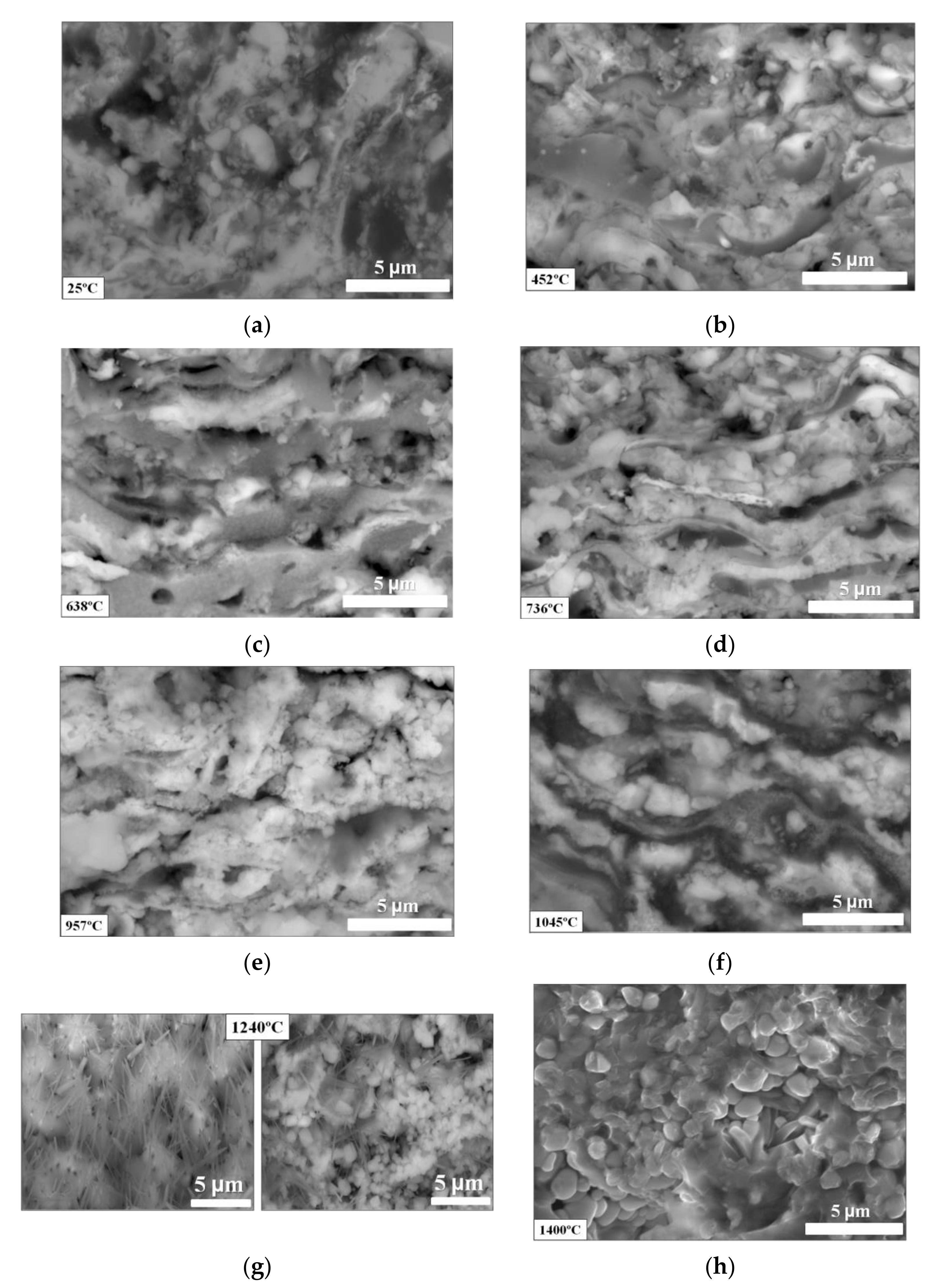
The thermal degradation process of the ZrB2–35MoSi2–10Al coating can be divided into three temperature stages;
-
The crystallization of the monoclinic phase of zirconium dioxide (m-ZrO2) takes place at 450 °C;
-
The actual onset of thermal degradation in the coating into other phases—such as c-Al12Mo, m-SiO2, and t-ZrO2—occurred from 640 to 960 °C;
-
The complete oxidation of the starting materials into the phases c-ZrO2, m-ZrO2, t-ZrSiO4, and mullite takes place with annealing temperature from 960 to 1400 °C;
-
The dense silicate glass layer containing ZrO2 and small amounts of mullite and zircon was formed during the oxidation. The ZrO2 and zircon particles (immiscible phases) were inlaid in SiO2 glass, so they could enhance its stability and prevent the propagation of cracks in the coating.
The experimental results can provide the basis for detonation spraying on C/C composites of a high-quality ceramic ZrB2–35MoSi2–10Al coating that can improve the properties of carbon–carbon composites in an oxygen-containing environment at elevated temperatures.

Author Contributions

Conceptualization, M.K.; data curation, V.N. and Y.T.; formal analysis, M.K., V.S., Y.T. and I.P.; investigation, I.G., O.V. and I.P.; methodology, M.Y. and V.S.; writing—original draft preparation, M.K. All authors have read and agreed to the published version of the manuscript.

Funding

This research was funded by the Russian Science Foundation, under grant No 19-19-00274. The work was carried out using the equipment of the Joint Research Center of Belgorod State National Research University—Technology and Materials—, with financial support from the Ministry of Science and Higher Education of the Russian Federation, within the framework of agreement No. 075-15-2021-690 (unique identifier for the project RF----2296.61321X0030).

Institutional Review Board Statement

Not applicable.

Informed Consent Statement

Not applicable.

Data Availability Statement

The data presented in this study are available on request from the corresponding author.

Conflicts of Interest

The authors declare no conflict of interest.

References

  1. Krenkel, W.; Berndt, F. C/C–SiC Composites for Space Applications and Advanced Friction Systems. Mater. Sci. Eng. A 2005, 412, 177–181. [Google Scholar] [CrossRef]
  2. Devi, G.; Rao, K. Carbon-Carbon Composites—An Overview. Def. Sci. J. 1993, 43, 369–383. [Google Scholar] [CrossRef]
  3. Lalit, M.M. High Performance Carbon–Carbon Composites. Sadhana 2003, 28, 349–358. [Google Scholar] [CrossRef] [Green Version]
  4. Windhorst, T.; Blount, G. Carbon-Carbon Composites: A Summary of Recent Developments and Applications. Mater. Des. 1997, 18, 11–15. [Google Scholar] [CrossRef]
  5. Zmij, V.I.; Rudenkyi, S.G.; Shepelev, A.G. Complex Protective Coatings for Graphite and Carbon-Carbon Composite Materials. Mater. Sci. Appl. 2015, 6, 879–888. [Google Scholar] [CrossRef] [Green Version]
  6. Chen, S.; Qiu, X.; Zhang, B.; Xu, J.; Zhong, F.; Zhu, B.; Zhang, Y.; Ou-Yang, J.; Yang, X. Advances in Antioxidation Coating Materials for Carbon/Carbon. J. Alloys Compd. 2021, 886, 161143. [Google Scholar] [CrossRef]
  7. Morimoto, T.; Ogura, Y.; Kondo, M.; Ueda, T. Multilayer Coating for Carbon-Carbon Composites. Carbon 1995, 33, 351–357. [Google Scholar] [CrossRef]
  8. Wu, S.J.; Cheng, L.F.; Zhang, L.T.; Xu, Y. Oxidation Behavior of 2D C/SiC with a Multi-Layer CVD SiC Coating. Surf. Coat. Technol. 2006, 200, 4489–4492. [Google Scholar] [CrossRef]
  9. Fritze, H.; Jojic, J.; Witke, T.; Rüscher, C.; Weber, S.; Scherrer, S.; Schultrich, B.; Borchardt, G. Mullite Based Oxidation Protection for SiC–C/C Composites in Air at Temperatures up to 1900 K. J. Eur. Ceram. Soc. 1998, 18, 2351–2364. [Google Scholar] [CrossRef]
  10. Ren, C.; He, Y.D.; Wang, D.R. Cyclic Oxidation Behavior and Thermal Barrier Effect of YSZ–(Al2O3/YAG) Double-Layer TBCs Prepared by the Composite Sol-Gel Method. Surf. Coat. Technol. 2011, 206, 1461–1468. [Google Scholar] [CrossRef]
  11. Zeng, Y.; Xiong, X.; Guo, S.; Zhang, W. SiC/SiC–YAG–YSZ Oxidation Protective Coatings for Carbon/Carbon Composites. Corros. Sci. 2013, 70, 68–73. [Google Scholar] [CrossRef]
  12. Yan, Z.Q.; Xiong, X.; Xiao, P.; Chen, F.; Zhang, H.-B.; Huang, B.-Y. A Multilayer Coating of Dense SiC Alternated with Porous Si–Mo for the Oxidation Protection of Carbon/Carbon Silicon Carbide Composites. Carbon 2008, 46, 149–153. [Google Scholar] [CrossRef]
  13. Huang, J.F.; Zeng, X.R.; Li, H.J.; Xiong, X.-B.; Fu, Y. Influence of the Preparation Temperature on Phase, Microstructure and Anti-Oxidation Property of SiC Coating for C/C Composites. Carbon 2004, 42, 1517–1521. [Google Scholar] [CrossRef]
  14. Smeacetto, F.; Salvo, M.; Ferraris, M. Oxidation Protective Multilayer Coatings for Carbon–Carbon Composites. Carbon 2002, 40, 583–587. [Google Scholar] [CrossRef]
  15. Grilli, M.L.; Valerini, D.; Slobozeanu, A.E.; Postolnyi, B.O.; Balos, S.; Rizzo, A.; Piticescu, R.R. Critical Raw Materials Saving by Protective Coatings under Extreme Conditions: A Review of Last Trends in Alloys and Coatings for Aerospace Engine Applications. Materials 2021, 14, 1656. [Google Scholar] [CrossRef]
  16. Yao, X.Y.; Li, H.J.; Zhang, Y.L.; Ren, J.-J.; Yao, D.-J.; Tao, J. A SiC/ZrB2–SiC/SiC Oxidation Resistance Multilayer Coating for Carbon/Carbon Composites. Corros. Sci. 2012, 57, 148–153. [Google Scholar] [CrossRef]
  17. Zhang, W.Z.; Yi, Z.; Lemuel, G.; Xiang, X.; Bai-Yun, H. Preparation and Oxidation Property of ZrB2-MoSi2/SiC Coating on Carbon/Carbon Composites. Trans. Nonferr. Met. Soc. China 2011, 21, 1538–1544. [Google Scholar] [CrossRef]
  18. Zhang, Y.L.; Li, H.J.; Yao, X.Y.; Li, K.-Z.; Qiang, X.-F. Oxidation Protection of C/SiC Coated Carbon/Carbon Composites with Si–Mo Coating at High Temperature. Corros. Sci. 2011, 53, 2075–2079. [Google Scholar] [CrossRef]
  19. Liu, G.H.; Cheng, L.F.; Li, K.Z.; Chen, Z.; Xiong, X.; Luana, X. Damage Behavior of Atomic Oxygen on Zirconium Carbide Coating Modified Carbon/Carbon Composite. Ceram. Int. 2020, 46, 3324–3331. [Google Scholar] [CrossRef]
  20. Hu, D.; Fu, Q.G.; Liu, T.Y.; Tong, M. Structural Design and Ablation Performance of ZrB2/MoSi2 Laminated Coating for SiC Coated Carbon/Carbon Composites. J. Eur. Ceram. Soc. 2020, 40, 212–219. [Google Scholar] [CrossRef]
  21. Ren, X.R.; Chu, H.A.; Wu, K.Y.; Zhang, A.; Huang, M.; Ma, C.; Liu, H.; Feng, P. Effect of the ZrB2 Content on the Oxygen Blocking Ability of ZrB2-SiC Coating at 1973 K. J. Eur. Ceram. Soc. 2020, 41, 1059–1070. [Google Scholar] [CrossRef]
  22. Li, C.Y.; Li, G.B.; Ouyang, H.B.; Lu, J. ZrB2 Particles Reinforced Glass Coating for Oxidation Protection of Carbon/Carbon Composites. J. Adv. Ceram. 2019, 8, 102–111. [Google Scholar] [CrossRef] [Green Version]
  23. Min-Kang, S. The Effect of MoSi2 on the Oxidation Behavior of Carbon/Carbon Composites. Carbon 2001, 39, 1229–1235. [Google Scholar] [CrossRef]
  24. Mao, J.Y.; Liu, M.; Mao, J. Oxidation-resistance of ZrB2-MoSi2 Composite Coatings Prepared by Atmospheric Plasma Spraying. J. Inorg. Mater. 2015, 39, 282–286. [Google Scholar] [CrossRef]
  25. Huang, Y.; Huang, J.F.; Cao, L.Y.; Li, C.; Hao, W.; Zhu, K. Influence of Solvothermal Treatment Time on Oxidation of Carbon/Carbon Composites Containing ZrB2 Microparticles. Ceram. Int. 2014, 40, 13529–13535. [Google Scholar] [CrossRef]
  26. Yao, X.Y.; Li, H.J.; Zhang, Y.L.; Wang, Y. Oxidation and Mechanical Properties of SiC/SiCMoSi2-ZrB2 Coating for Carbon/Carbon Composites. J. Mater. Sci. Technol. 2014, 30, 123–127. [Google Scholar] [CrossRef]
  27. Jiang, Y.; Feng, D.; Ru, H.Q.; Wang, W.; Zhang, C. Oxidation Protective ZrB2-MoSi2-SiC-Si Coating for Graphite Materials Prepared by Slurry Dipping and Vapor Silicon Infiltration. Surf. Coat. Technol. 2018, 339, 91–100. [Google Scholar] [CrossRef]
  28. Yang, X.; Wei, L.; Song, W.; Bi-Feng, Z.; Zhao-Hui, C. ZrB2/SiC as a Protective Coating for C/SiC Composites: Effect of High Temperature Oxidation on Mechanical Properties and Anti-Ablation Property. Compos. Part B Eng. 2013, 45, 1391–1396. [Google Scholar] [CrossRef]
  29. Yang, X.; Feng, C.; Qing, W. ZrB2-SiC as a Protective Coating for C/SiC Composites: Effect of High Temperature Oxidation on Thermal Shock Property and Protection Mechanism. J. Asian Ceram. 2016, 4, 159–163. [Google Scholar] [CrossRef] [Green Version]
  30. Niu, Y.; Wang, Z.; Zhao, J.; Zheng, X.; Zeng, Y.; Ding, C. Comparison of ZrB2-MoSi2 Composite Coatings Fabricated by Atmospheric and Vacuum Plasma Spray Processes. J. Therm. Spray Technol. 2017, 26, 100–107. [Google Scholar] [CrossRef]
  31. Liu, X.; Han, W.; Wen, K.; Deng, C.; Deng, C.; Liu, M.; Zhou, K. Bimodal Microstructure ZrB2-MoSi2 Coating Prepared by Atmospheric Plasma Spraying for Carbon/Carbon Composites Against Long-Term Ablation. Ceram. Int. 2017, 43, 16659–16667. [Google Scholar] [CrossRef]
  32. Podchernyaeva, I.A.; Grigoriev, O.N.; Panasyuk, A.D.; Evdokimenko, Y.I.; Kisel’, V.M.; Yurechko, D.V.; Panashenko, V.M. High-Temperature ZrB2-Based Coatings on Metallic Alloys Produced by High-Velocity Air-Fuel Thermal Spraying. Powder Metall. Met. Ceram. 2017, 55, 689–697. [Google Scholar] [CrossRef]
  33. Kovaleva, M.G.; Goncharov, I.Y.; Novikov, V.Y.; Yapryntsev, M.N.; Vagina, O.N.; Pavlenko, I.N.; Sirota, V.V.; Tyurin, Y.N.; Kolisnichenko, O.V. Characteristics of ZrB2-ZrO2-MoSi2-Al Coating on Carbon/Carbon Composite Obtained by a New Multi-chamber Detonation Accelerator. IOP Conf. Ser. Mater. Sci. Eng. 2020, 872, 012053. [Google Scholar] [CrossRef]
  34. Kovaleva, M.; Goncharov, I.; Novikov, V.; Yapryntsev, M.; Vagina, O.; Pavlenko, I.; Sirota, V.; Tyurin, Y.; Kolisnichenko, O. Effect of Heat Treatment on the Microstructure and Phase Composition of ZrB2–MoSi2 Coating. Coatings 2019, 9, 779. [Google Scholar] [CrossRef] [Green Version]
  35. Vasilik, N.; Tyurin, Y.; Kolisnichenko, O. Method for Gas-Dynamic Detonating Speedup of Powders and Device for Its Implementation. RU Patent 2,506,341, 11 July 2012. [Google Scholar]
  36. Kovaleva, M.; Tyurin, Y.; Vasilik, N.; Kolisnichenko, O.; Prozorova, M.; Arseenko, M.; Danshina, E. Deposition and Characterization of Al2O3 Coatings by Multi-Chamber Gas-Dynamic Accelerator. Surf. Coat. Technol. 2013, 232, 719–725. [Google Scholar] [CrossRef]
  37. Zhang, X.C.; Xu, B.S.; Wu, Y.X.; Xuan, F.Z.; Tu, S.-T. Porosity, mechanical properties, residual stresses of supersonic plasma-sprayed Ni-Based alloy coatings prepared at different powder feed rates. Appl. Surf. Sci. 2008, 254, 3879–3889. [Google Scholar] [CrossRef]
  38. Kovaleva, M.; Sirota, V.; Goncharov, I.; Novikov, V.; Yapryntsev, M.; Vagina, O.; Pavlenko, I.; Tyurin, Y.; Mogucheva, A. Kinetics Investigation of the Formation of a Gas-Resistant Glass-Forming Layer During the Oxidation of ZrB2-MoSi2-Y2O3-Al Coatings in the Air Atmosphere. Coatings 2021, 11, 1018. [Google Scholar] [CrossRef]
  39. Kovaleva, M.; Tyurin, Y.; Vasilik, N.; Kolisnichenko, O.; Prozorova, M.; Arseenko, M.; Yapryntsev, M.; Sirota, V.; Pavlenko, I. Effect of Processing Parameters on the Microstructure and Properties of WC–10Co–4Cr Coatings Formed by a New Multi-chamber Gas-Dynamic Accelerator. Ceram. Int. 2015, 41, 15067–15074. [Google Scholar] [CrossRef]
  40. Kovaleva, M.; Tyurin, Y.; Vasilik, N.; Kolisnichenko, O.; Prozorova, M.; Arseenko, M.; Sirota, V.; Pavlenko, I. Effect of Heat Treatment on the Microstructure and Microhardness of Nanostructural Al2O3 Coatings. J. Therm. Spray Technol. 2014, 23, 1199–1209. [Google Scholar] [CrossRef]
  41. Zhang, Y.L.; Li, H.J.; Qiang, X.F.; Li, K.-Z.; Zhang, S.-Y. C/SiC/MoSi2-Si Multilayer Coatings for Carbon/Carbon Composites for Protection Against Oxidation. Corros. Sci. 2011, 53, 3840–3844. [Google Scholar] [CrossRef]
  42. Fu, Q.G.; Li, H.J.; Wang, Y.J.; Li, K.-Z.; Shi, X.-H. B2O3 Modified SiC-MoSi2 Oxidation Resistant Coating for Carbon/Carbon Composites by a Two-Step Pack Cementation. Corros. Sci. 2009, 51, 2450–2454. [Google Scholar] [CrossRef]
  43. Enzo, S.; Frattini, R.; Canton, P.; Monagheddu, M.; Delogu, F. Neutron Diffraction Study of Mechanically Alloyed and In Situ Annealed Al75Mo25 Powders. J. Appl. Phys. 2000, 87, 2753–2759. [Google Scholar] [CrossRef] [Green Version]
  44. Grushko, B.; Velikanova, T.Y. Formation of Quasicrystals and Related Structures in Systems of Aluminum with Transition Metals. I. Binary Systems Formed by Aluminum with 3d Metals. Powder Metall. Met. Ceram. 2004, 43, 72–86. [Google Scholar] [CrossRef]
  45. Bian, Y.; Gao, T.; Li, Z.; Sun, Q.; Ma, X.; Liu, X. In–Situ Synthesis of an Al Composite Reinforced with Multi–Scale Al12Mo, (Al, Zr, Si) and Al2O3 Particles through a Multi–Stage Reaction. Mater. Sci. Eng. A 2019, 762, 138069. [Google Scholar] [CrossRef]
  46. Colgan, E.G.; Nastasi, M.; Mayer, J.W. Initial Phase Formation and Dissociation in the Thin Film Ni/Al System. J. Appl. Phys. 1985, 58, 4125–4129. [Google Scholar] [CrossRef]
  47. Kaiser, A.; Lobert, M.; Telle, R. Thermal Stability of Zircon (ZrSiO4). J. Eur. Ceram. Soc. 2008, 28, 2199–2211. [Google Scholar] [CrossRef]
  48. Elsandika, G.; Putri, A.D.C.; Musyarofah, M.; Pratapa, S. Synthesis of ZrSiO4 Powders by a Sol-Gel Method with Varied Calcination Temperatures. IOP Conf. Ser. Mater. Sci. Eng. 2019, 496, 012047. [Google Scholar] [CrossRef]
  49. Ferrari, S.; Grinblat, F.; Bilovol, V.; Pampillo, L.G.; Saccone, F.D.; Errandonea, D.; Chanquía, C.M. Synthesis and Characterization of Ti-Doped ZrSiO4 at Ambient and High-Pressure Conditions. J. Mater. Sci. 2018, 53, 8817–8825. [Google Scholar] [CrossRef]
  50. Yan, S.; Yang, Q.; Wang, H.; Zhang, Q. Depression of Synthesis Temperature and Structure Characterization of ZrSiO4 Used in Ceramic Pigments. Mater. Chem. Phys. 2018, 205, 97–101. [Google Scholar] [CrossRef]
  51. Wang, C.; Li, K.; He, Q.; He, D.; Huo, C.; Su, Y.; Shi, X.; Li, H. Oxidation and Ablation Protection of Plasma Sprayed LaB6-MoSi2-ZrB2 Coating for Carbon/Carbon Composites. Corros. Sci. 2019, 151, 57–68. [Google Scholar] [CrossRef]
  52. Zhuo, G.; Su, L.; Jiang, K.; Yang, J. Effect of Spraying Power on Oxidation Resistance Of MoSi2-ZrB2 Coating for Nb-Si Based Alloy Prepared by Atmospheric Plasma. Materials 2020, 13, 5060. [Google Scholar] [CrossRef] [PubMed]
  53. Fu, Q.G.; Li, H.J.; Shi, X.H.; Li, K.-Z.; Sun, G.-D. Silicon Carbide Coating to Protect Carbon/Carbon Composites Against Oxidation. Script. Mater. 2005, 52, 923–927. [Google Scholar] [CrossRef]
  54. Niu, Y.; Wang, H.; Liu, Z.; Hu, C.; Wang, X.; Zheng, X.; Ding, C. Microstructure Evolution of ZrB2–MoSi2 Composite Coatings at Middle and High Temperatures. Surf. Coat. Technol. 2015, 273, 30–38. [Google Scholar] [CrossRef]
  55. Fei, X.; Niu, Y.; Ji, H.; Huang, L.; Zheng, X. A Comparative Study of MoSi2 Coatings Manufactured by Atmospheric and Vacuum Plasma Spray Processes. Ceram. Int. 2011, 37, 813–817. [Google Scholar] [CrossRef]
Figure 1. SEM-BSE micrograph (a) and XRD pattern (b) of the ZrB2–35MoSi2–10Al powder.
Coatings 11 01531 g001
Figure 2. Robotic complex for detonation spraying of coatings (IntelMashin LLC., Moscow, Russia) equipped with a multi-chamber detonation accelerator (MCDS).
Coatings 11 01531 g002
Figure 3. TGA-DSC curves (a) and X-ray diffraction patterns of the ZrB2-35MoSi2-10Al coating at different temperatures: from RT to 736 °C (b); from 957 to 1400 °C (c).
Coatings 11 01531 g003
Figure 4. The as-sprayed ZrB2–35MoSi2–10Al coating: surface SEM-BSE micrograph (a), X-ray pattern (b), SEM-BSE micrograph plane view of the cross-section of the system «ZrB2–MoSi2 coating—C/C composite» with low (c) and high magnification (d,e).
Coatings 11 01531 g004
Figure 5. The ZrB2–35MoSi2–10Al coating after treatment at 1400 °C: surface SEM-BSE micrograph (a) and SEM EDX element distribution map (b); X-ray pattern (c), cross-section SEM-BSE micrograph (d,e); EDX elemental analysis from points 1, 2 (f).
Coatings 11 01531 g005
Figure 6. SEM-BSE micrographs of fractured surface of the ZrB2–35MoSi2>–10Al coating after treatment at different temperatures: RT (a), 452 °C (b), 638 °C (c), 736 °C (d), 957 °C (e), 1045 °C (f), 1240 °C (g), and 1400 °C (h).
Coatings 11 01531 g006
Table 1. Spraying parameters of the coating.
Barrel Length (mm)Barrel Diameter (mm)Powder Feed Rate (g/h)Flow Rate of Fuel Mixture Components, m3/hOxygen/Fuel Ratio
OxygenC3H8 + C4H10Air
500166004.00 */3.60 **0.75 */0.68 **0.12 */0.12 **5.28 */5.38 **
* Cylindrical-form combustion chamber; ** combustion chamber in the form of a disk.
Publisher’s Note: MDPI stays neutral with regard to jurisdictional claims in published maps and institutional affiliations.

