Article

Enhancing Electrical Conductivity and Corrosion Resistance of CrN Coating by Pt Addition

1
Precision Forming Center, Southwest Technology and Engineering Research Institute, Chongqing 400039, China
2
Liaoning Key Laboratory of Complex Workpiece Surface Special Machining, University of Science and Technology Liaoning, Anshan 114051, China
3
Department of Intelligent Manufacturing, Linyi Vocational University of Science and Technology, Linyi 276025, China
*
Authors to whom correspondence should be addressed.
Coatings 2021, 11(12), 1479; https://doi.org/10.3390/coatings11121479
Submission received: 21 October 2021 / Revised: 25 November 2021 / Accepted: 27 November 2021 / Published: 1 December 2021
(This article belongs to the Special Issue Advances in Corrosion Resistant Coatings)

Abstract

:
Transition-metal nitride coating used to protect the electronic connector devices in marine environment is required to have high electrical conductivity and good corrosion resistance. This study synthesized a novel CrN–Pt coating with a dense growth texture. Pt addition induced a pronounced increase in electrical conductivity and corrosion resistance. The resistivity decreased from 0.0149 Ohm·cm in the CrN coating to 0.000472 Ohm·cm in the CrN–Pt coating, while the corrosion current density decreased from 24 nA/cm2 in the CrN coating to 6.3 nA/cm2 in the CrN–Pt coating. The results of the above studies confirm that Pt doping has significant advantages in improving the electrical conductivity and corrosion resistance of nitride coatings for potential applications in the marine environment.

1. Introduction

Electrical connector metals suffer from severe passivation reaction or galvanic corrosion when exposed to the marine environment. The passivation films or corrosion products formed on their surface greatly degrade the efficiency of signal transmission, and consequently result in a pronounced decrease in reliability of electronic equipment [1,2,3]. Fabrication of advanced functional coatings is a feasible strategy to prolong the service life of electrical connectors in marine environments; however, such coatings must have low resistivity and excellent corrosion resistance.
Transition-metal nitride coatings have high hardness, good chemical inertness and high resistance to wear and corrosion. These characteristics make them promising candidates for resisting severe tribocorrosion in marine environments [4,5,6,7,8,9,10,11,12,13,14,15,16,17,18]. The binary chromium nitride (CrN) coatings were developed in order to enhance resistance to wear and corrosion in high speed rotating parts; however, these coatings showed unsatisfactory service life in industrial applications [13]. In some harsh working environments, such as seawater, the corrosion resistance of CrN coatings does not meet requirements for long service life. Ternary CrXN coatings, where X = W, Mo, Al, Ti, Si, C, etc. [6,7,9,10,11,12,16,17,18,19,20], have proven to have better mechanical, tribological and anti-corrosion properties. In contrast, the Pt element has high chemical inertness and good corrosion resistance, and Pt doping is expected to effectively enhance the corrosion resistance of CrN coatings. However, thus far there have been no reports on the Pt doping in CrN coatings. Moreover, relatively little work about the electrical conductivity of these coatings has been carried out. Here, a novel CrN–Pt coating was prepared by plasma enhanced magnetron sputtering (PEMS). The potential effects of Pt doping on the growth structure, electrical conductivity and corrosion property of the CrN coating were studied by the detailed characterizations.

2. Experimental Details

The CrN and CrN–Pt coatings were synthesized using the PEMS technique [21]. High pure chromium (99.6%) and platinum (99.9%) were used as the targets. For the substrate, 316 L austenitic steel and silicon wafer were selected. These specimens were polished with metallographic sandpaper, then washed ultrasonically in pure alcohol for 15 min. All specimens were fastened to a rotating substrate holder. Prior to preparing the coating, specimens were thoroughly etched with Ar+ ions having a −120 V bias voltage, 100 sccm argon flow and 60 min sputtering time. A Cr metal layer was first deposited on the substrate in argon gas atmosphere. The bias voltage, argon flow, power and sputtering time were −100 V, 100 sccm, 5000 W and 5 min, respectively. The top CrN and CrN–Pt coatings were prepared in a gaseous mixtures consisting of high purity Ar (99.99%) and N2 (99.99%). During coating deposition, additional tungsten filaments acted as electron emission sources in order to trigger ionization of the gas and metal atoms. These ionized N ions subsequently reacted with metal ions to form the nitride coating. The as-deposited coatings were prepared with the following parameters: −100 V bias voltage, 100 sccm argon gas flow, 100 sccm nitrogen gas flow, 5000 W power and 100 min coating time. The compositions of the as-deposited coatings were determined using an energy dispersive X-ray spectroscopy (EDS, Bruker, Karlsruhe, Germany) instrument equipped with scanning electron microscopy (SEM, Zeiss ∑IGMA HD, Carl Zeiss, Jena, Germany). X-ray diffraction (XRD, X’ Pert Powder, PANalytical B.V., Almelo, the Netherlands) was carried out in order to study the crystal structures of all coatings within the 2θ scanned range from 20° to 90°. The growth textures of all coatings were observed by scanning electron microscopy (SEM, Zeiss ∑IGMA HD). Atomic force microscopy (AFM, Oxford MFP-3DInfinity, Abingdon, UK) was employed in order to evaluate the surface roughness (Ra) of the coatings. The resistivity of the coatings was obtained using a Hall effect measurement system (Hall 8800, Precision Systems Industrial Limited, Taiwan, China) at a room temperature of 25 °C. The corrosion tests were executed using an electrochemical station (CHI760e, Chenhua Instrument Corp, Shanghai, China). The corrosive medium was NaCl solution with a concentration of 3.5 wt.%. The reference electrode (RE), counter electrode (CE) and working electrode (WE) were a saturated calomel electrode (SCE), Pt plate, and coating specimen, respectively. The exposed area of the coating sample was 1 cm2. The length, width, and height of the Pt plate were 10, 10, and 0.5 mm, respectively. All electrodes were placed in a standard cell. The scan was in a range of −0.3~1 V. The scan rate was 1 mV/s. The statistical potential (Ecorr) and current density (icorr) were employed to evaluate the corrosion resistance. According to Equation (1), the protective efficacy of the coating can be calculated as
Protective   efficacy   ( Pi ) = ( 1 i corr i corr 0 ) × 100 %
where i corr and i corr 0 represent the corrosion current density of the coating with and without Pt doping, respectively.
In addition, electrochemical impedance spectroscopy (EIS) tests were executed and collected in the frequency range of 100 kHz to 0.01 Hz. Each test was repeated three times under the same conditions in order to check the reproducibility. The surface topographies of all coatings following the corrosion tests were observed by SEM.

3. Results and Discussions

Table 1 summarizes the compositions of the CrN and CrN–Pt coatings. The composition of the CrN coating is 53.48 at.% chromium, 45.16 at.% nitrogen and 1.36 at.% oxygen. By contrast, the composition of the CrN–Pt coating is 45.97 at.% chromium, 39.26 at.% nitrogen, 13.33 at.% platinum and 1.44 at.% oxygen. The trace amount of oxygen can likely be attributed to adsorption during air exposure.
Figure 1 shows the SEM surface image and element mapping of the CrN–Pt coating. It can be seen that the as-deposited CrN–Pt coating exhibits smooth surface feature. The corresponding element mapping reveals that these component elements (e.g., Pt and Cr) shows relatively uniform distribution in the as-deposited coating. It has been reported that nitride/Ag composite film has a two-phase structure consisting of metallic Ag and a nitride matrix. The Ag may be dissolved in the ceramic matrix or exist as an isolated phase [22,23]. According to these above results, these Pt atoms are likely solute within the CrN matrix or independently distributed at grain boundaries.
Figure 2 illustrates the XRD results of the CrN and CrN–Pt coatings. The diffraction peaks of the CrN coating are mainly centered at 36.82°, 43.24°, 62.75° and 75.36°, assigned to the (111), (200), (220) and (311) crystal planes of the CrN phases (JCPDS 11-0065). These CrN phases are also detected in the CrN–Pt coating, while three clearly characteristic peaks at 39.88°, 46.07° and 68.24° are simultaneously detected in this coating, attributed to the (111), (200) and (220) planes of metallic-state Pt (JCPDS 87-0640). The partial enlarged drawing inserted in Figure 2 reveals that the strong (200) diffraction peak in the CrN–Pt coating shows a slight leftward shift compared to the CrN coating. According to EDS characterization, these Pt atoms are mainly distributed at the grain boundaries; however, a small amount of Pt atoms are also dissolved in the CrN matrix. In both cases local internal stress and lattice distortion are induced, eventually resulting in a significant shift of the diffraction peak [24,25,26,27].
Figure 3 shows the AFM surface images of the as-deposited CrN and CrN–Pt coatings. It can be seen that Pt doping induces a significant surface modification effect. As shown in Figure 3a, the CrN coating exhibits a relatively coarse surface, with a high Ra value of 3.05 nm. Numerous large grains can be identified in the local enlarged AFM image of the CrN coating. By contrast, the CrN–Pt coating shows improved surface quality, reflected by a smoother surface and a lower Ra value of 0.932 nm. The local enlarged AFM image reveals that more and smaller grains are closely packed to form a dense texture in the CrN–Pt coating.
Figure 4 presents the SEM images of all coatings. The CrN coating exhibits a loose and coarse oatmeal-like surface; as shown in Figure 4a, pinholes and irregular particles appear on the surface. The cross-sectional image reveals that the CrN coating shows a discontinuous columnar crystal growth pattern, resulting in a loose texture (see Figure 4b). By contrast, the CrN–Pt coating exhibits a dense surface; as shown in Figure 4c, many refined grains appear on the surface, indicating a prominent grain refinement effect. Meanwhile, this coating shows a nearly continuous columnar growth pattern, reflected by a dense and fine columnar texture topography (see Figure 4d). The CrN and CrN–Pt films have thicknesses of 690 and 703 nm, respectively.
Figure 5 shows the resistivity variations of the as-deposited CrN and CrN–Pt coatings. The resistivity value of the CrN coating is about 0.0149 Ohm·cm. By contrast, the CrN–Pt coating shows a lower resistivity value of 0.000472 Ohm·cm, indicating a significant increase in electrical conductivity with the addition of Pt. Based on the XRD characterization results, the CrN–Pt coating has a typical composite structure consisting of the CrN and Pt phases. A small amount of metallic-state Pt forms in the CrN matrix, which can act as a considerable electrical conductor and consequently results in a pronounced decrease in the resistivity of the CrN coating.
Figure 6a displays the polarization curves and statistical data of the coatings. The Ecorr and icorr of the CrN coating are −0.137 V and 24 nA/cm2, respectively. By contrast, the CrN–Pt coating shows improved resistance to corrosion, with a higher Ecorr of 0.136 V and a lower icorr of 6.3 nA/cm2. In addition, the protective efficacy of the coating (Pi) is 73.75%. The corrosion image reveals that the CrN coating suffered from severe corrosion degradation during the corrosion test; as shown in Figure 6b, a large number of pitting holes as well as visible delamination can be observed on the coating’s surface. In comparison, the CrN–Pt coating retains a dense surface topography, without pitting holes or local delamination, indicating superior corrosion resistance (Figure 6c).
Figure 7 shows the EIS results of the CrN and CrN–Pt coatings. It is well known that the semicircle with a larger diameter corresponds to better corrosion resistance. The CrN–Pt coating shows a larger semicircle in comparison to that of the CrN coating, indicating improved corrosion resistance. The equivalent circuit inserted in Figure 7 shows that the Rct corresponds to the charge transfer resistance of the coating. The Rct value of the CrN coating is 3.28 × 10⁶ Ω·cm2, which is lower than that of the CrN–Pt coating (8.82 × 10⁶ Ω·cm2). These electrochemical test results clearly indicate that the CrN–Pt coating provides better corrosion protection for the substrate in comparison to the CrN coating.
The CrN coating shows unsatisfactory resistance to corrosion, which can be likely attributed to its loose growth texture; as identified in the SEM results of Figure 4a,b, a large number of pinholes form at the grain boundary, which can act as the diffusion channel of corrosion medium and consequently results in the occurrence of local pitting corrosion [28]. The loose growth textures further accelerate the inner diffusion of corrosive media, triggering a prominent intergranular corrosion degradation that greatly weakens the bonding strength of adjacent grains or textures and eventually results in the appearance of pitting holes or local coating delamination (see Figure 6b). By contrast, the CrN–Pt coating shows a significant increase in corrosion resistance, which can likely be attributed to the dense growth texture and high chemical inertness of the doped Pt element. As shown in Figure 4c,d, Pt addition induces a pronounced structural modification of the CrN coating, triggering the formation of dense growth texture and refined grain size in the CrN–Pt coating. Compared with the CrN coating, the refined growth texture greatly inhibits the multi-scale diffusion of solution and further prevents the occurrence of local pitting corrosion, while the refined grain size is generally believed to benefit corrosion resistance in the CrN–Pt coating. The XRD results of Figure 1 confirm that the CrN–Pt coating has a typical composite structure of CrN and Pt. These metallic-state Pt atoms have high chemical inertness and good corrosion resistance, which effectively inhibits intergranular and grain boundary corrosion. As a result, the synergistic effects of dense texture, grain refinement and high inertness obtained with Pt doping eventually lead to the excellent corrosion resistance of the CrN–Pt coating.

4. Conclusions

This work investigated the microstructure, electrical conductivity and corrosion resistance of CrN and CrN–Pt coatings. The CrN coating showed a loose growth texture that provided multi-scale diffusion channels for corrosive media, which consequently resulted in severe pitting corrosion and coating delamination. The CrN–Pt coating exhibited a dense composite structure consisting of CrN and metallic-state Pt. The dense texture greatly depressed local pitting corrosion, while the highly inert Pt effectively inhibited intergranular and grain boundary corrosion. Meanwhile, the refined grains showed a positive response in terms of resisting corrosive attack. The strong synergistic effects of dense texture and grain refinement provided by Pt doping led to the superior corrosion resistance of the CrN–Pt coating. The metallic-state Pt atoms had good electrical conductivity and induced a pronounced decrease in the resistivity of the CrN–Pt coating.

Author Contributions

Conceptualization, H.W.; methodology, Y.W.; investigation, G.S. and L.X.; supervision, Z.X. All authors have read and agreed to the published version of the manuscript.

Funding

This work was supported by the National Natural Science Project of China (51771087, 52171076), Graduate Education Reform and Science and Technology Innovation Project of University of Science and Technology Liaoning (LKDYC202019), Southwest Institute of Technology and Engineering Cooperation Fund (HDHDW5902020103), University of Science and Technology Liaoning Talent Project Grants (601011507-07).

Institutional Review Board Statement

Not applicable.

Informed Consent Statement

Not applicable.

Data Availability Statement

No new data were created or analyzed in this study. Data sharing is not applicable to this article.

Acknowledgments

We sincerely thank professor Feng Gong for the coating deposition.

Conflicts of Interest

The authors declare no conflict of interest.

References

  1. Wang, J.Z.; Yan, F.Y.; Xue, Q.J. Friction and wear behavior of ultra-high molecular weight polyethylene sliding against GCr15 steel and electroless Ni-P alloy coating under the lubrication of seawater. Tribol. Lett. 2009, 35, 85–95. [Google Scholar] [CrossRef]
  2. Hannel, S.; Fouvry, S.; Kapsa, P.H.; Vinent, L. The fretting sliding transition as a criterion for electrical contact performance. Wear 2001, 249, 761–770. [Google Scholar] [CrossRef]
  3. Wang, J.J.; Pu, J.B.; Zhang, G.G.; Wang, L.P. Architecture of superthick diamond-like carbon films with excellent high temperature wear resistance. Tribol. Int. 2015, 81, 129–138. [Google Scholar] [CrossRef]
  4. Rezaee, S.; Arman, A.; Jurečka, S.; Korpi, A.G.; Mwema, F.; Luna, C.; Sobola, D.; Kulesza, S.; Shakoury, R.; Bramowicz, M.; et al. Effect of annealing on the micromorphology and corrosion properties of Ti/SS thin films. Superlattices Microstr. 2020, 146, 106681. [Google Scholar] [CrossRef]
  5. Rahman, A.M.A.E. Synthesis and annealing effects on the properties of nanostructured Ti-Al-V-N coatings deposited by plasma enhanced magnetron sputtering. Mater. Chem. Phys. 2015, 149, 179–187. [Google Scholar] [CrossRef]
  6. Wan, Z.; Zhang, T.F.; Lee, H.B.R.; Yang, J.H.; Choi, W.C.; Han, B.; Kim, K.H.; Kwon, S.H. Improved corrosion resistance and mechanical properties of CrN hard coatings with an atomic layer deposited Al2O3 interlayer. ACS Appl. Mater. Inter. 2015, 7, 26716–26725. [Google Scholar] [CrossRef]
  7. Madaoui, N.; Saoula, N.; Zaid, B.; Saidi, D.; Ahmed, A.S. Structural, mechanical and electrochemical comparison of TiN and TiCN coatings on XC48 steel substrates in NaCl 3.5% water solution. Appl. Surf. Sci. 2014, 312, 134–138. [Google Scholar] [CrossRef]
  8. Ruden, A.; Restrepo Parra, E.; Paladines, A.U.; Sequeda, F. Corrosion resistance of CrN thin films produced by dc magnetron sputtering. Appl. Surf. Sci. 2013, 270, 150–156. [Google Scholar] [CrossRef]
  9. Martinez, E.; Sanjinés, R.; Karimi, A.; Esteve, J.; Lévy, F. Mechanical properties of nanocomposite and multilayered Cr-Si-N sputtered thin films. Surf. Coat. Technol. 2004, 180, 570–574. [Google Scholar] [CrossRef]
  10. Gilewicz, A.; Warcholinski, B. Tribological properties of CrCN/CrN multilayer coatings. Tribol. Int. 2014, 80, 34–40. [Google Scholar] [CrossRef]
  11. Xu, X.; Sun, J.F.; Xu, Z.B.; Li, Z.J.; Su, F.H. Microstructure, electrochemical and tribocorrosion behaviors of CrCN nanocomposite coating with various carbon content. Surf. Coat. Technol. 2021, 411, 126997. [Google Scholar] [CrossRef]
  12. Wang, Y.X.; Zhang, J.W.; Zhou, S.G.; Wang, Y.C.; Wang, C.T.; Wang, Y.X.; Sui, Y.F.; Lan, J.B.; Xue, Q. Improvement in the tribocorrosion performance of CrCN coating by multilayered design for marine protective application. Appl. Surf. Sci. 2020, 528, 147061. [Google Scholar] [CrossRef]
  13. Lamastra, F.R.; Leonardi, F.; Montanari, R.; Casadei, F.; Valente, T.; Gusmano, G. X-ray residual stress analysis on CrN/Cr/CrN multilayer PVD coatings deposited on different steel substrates. Surf. Coat. Technol. 2006, 200, 6172–6175. [Google Scholar] [CrossRef]
  14. Greczynski, G.; Lu, J.; Petrov, I.; Greene, J.E.; Hultman, L. Nitrogen-doped bcc-Cr films: Combining ceramic hardness with metallic toughness and conductivity. Scr. Mater. 2016, 122, 40–44. [Google Scholar] [CrossRef] [Green Version]
  15. Fu, Y.Y.; Li, H.X.; Ji, L.; Liu, X.H.; Chen, J.M.; Wen, L.S. Insight into Al existing form and its role on microstructure and properties of Cr1-xAlxN films. Surf. Interface Anal. 2016, 48, 26–33. [Google Scholar] [CrossRef]
  16. Ibrahim, K.; Rahman, M.M.; Taha, H.; Mohammadpour, E.; Zhou, Z.F.; Yin, C.Y.; Nikoloski, A.; Jiang, Z.T. Structural, morphological, and optical characterizations of Mo, CrN and Mo:CrN sputtered coatings for potential solar selective applications. Appl. Surf. Sci. 2018, 440, 1001–1010. [Google Scholar] [CrossRef] [Green Version]
  17. Tan, S.Y.; Zhang, X.H.; Wu, X.J.; Fang, F.; Jiang, J.Q. Comparison study on structure of Si and Cu doping CrN films by reactive sputtering. Appl. Surf. Sci. 2011, 257, 5595–5600. [Google Scholar] [CrossRef]
  18. Qi, D.L.; Lei, H.; Wang, T.G.; Pei, Z.; Gong, J.; Sun, C. Mechanical, microstructural and tribological properties of reactive magnetron sputtered Cr-Mo-N films. J. Mater. Sci. Technol. 2015, 31, 55–64. [Google Scholar] [CrossRef]
  19. Kong, J.Z.; Hou, T.J.; Wang, Q.Z.; Yin, L.; Zhou, F.; Zhou, Z.F.; Li, K.Y. Influence of titanium or aluminum doping on the electrochemical properties of CrN coatings in artificial seawater. Surf. Coat. Technol. 2016, 307, 118–124. [Google Scholar] [CrossRef]
  20. Lin, J.; Mishra, B.; Moore, J.J.; Sproul, W.D. Microstructure, mechanical and tribological properties of Cr1−xAlxN films deposited by pulsed-closed field unbalanced magnetron sputtering (P-CFUBMS). Surf. Coat. Technol. 2006, 201, 4329–4334. [Google Scholar] [CrossRef]
  21. Huang, X.F.; Xie, Z.W.; Li, K.S.; Chen, Q.; Gong, F.; Chen, Y.J.; Hu, S.Y.; Chen, Y.; Han, B.; Wu, D.; et al. Gong, Microstructure, wear and oxidation resistance of CrWN glass molding coatings synthesized by plasma enhanced magnetron sputtering. Vacuum 2020, 174, 12–23. [Google Scholar] [CrossRef]
  22. Rajput, S.S.; Gangopadhyay, S.; Cavaleiro, A.; Al-Rjoub, A.; Kumar, C.S.; Fernandes, F. Influence of Ag additions on the structure, mechanical properties and oxidation behaviour of CrAlNAg coatings deposited by sputtering. Surf. Coat. Technol. 2018, 333, 167–180. [Google Scholar] [CrossRef]
  23. Hong, C.F.; Huan, Y.X.; Zhang, P.S.; Zhang, K.; Dai, P.Q. Effect of silver content on the microstructure, thermal stability and mechanical properties of CrNx/Ag nanocomposite films. Ceram. Int. 2021, 47, 25324–25336. [Google Scholar] [CrossRef]
  24. Heo, S.J.; Kim, S.W.; Yeo, I.W.; Park, S.J.; Oh, Y.S. Effect of bias voltage on microstructure and phase evolution of Cr-Mo-N coatings by an arc bonded sputter system. Ceram. Int. 2016, 42, 5231–5237. [Google Scholar] [CrossRef]
  25. Thornton, J.A.; Lamb, J.L. Thermal stability studies of sputter-deposited multilayer selective absorber coatings. Thin Solid Films 1982, 96, 175–183. [Google Scholar] [CrossRef]
  26. Bagcivan, N.; Bobzin, K.; Theiss, S. (Cr1-xAlx)N: A comparison of direct current, middle frequency pulsed and high power pulsed magnetron sputtering for injection molding components. Thin Solid Films 2013, 528, 180–186. [Google Scholar] [CrossRef]
  27. Pan, P.J.; Drnovsek, A.; Kovac, J.; Gselman, P.; Boncina, T.; Paskvale, S.; Cekada, M.; Merl, D.K.; Man, P.J. Oxidation resistance of CrN/(Cr,V)N hard coatings deposited by DC magnetron sputtering. Thin Solid Films 2015, 591, 323–329. [Google Scholar] [CrossRef]
  28. Beliardouh, N.E.; Bouzid, K.; Nouveau, C.; Tlili, B.; Walock, M.J. Tribological and electrochemical performances of Cr/CrN and Cr/CrN/CrAlN multilayer coatings deposited by RF magnetron sputtering. Tribol. Int. 2015, 82, 443–452. [Google Scholar] [CrossRef] [Green Version]
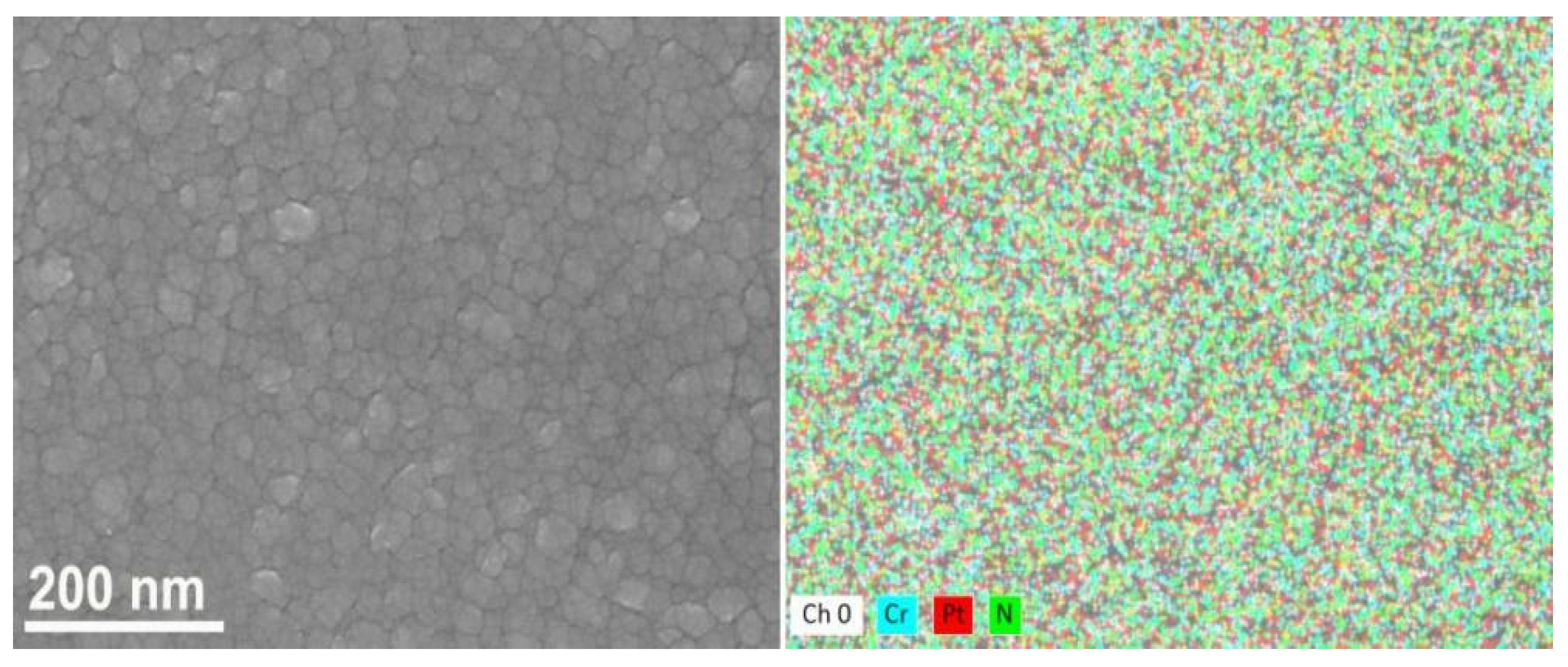
Figure 1. SEM image with corresponding element mapping of the CrN–Pt coating.
Coatings 11 01479 g001
Figure 2. XRD patterns of the as-deposited CrN and CrN–Pt coatings.
Coatings 11 01479 g002
Figure 3. AFM surface images of the as-deposited coatings: (a) CrN, (b) CrN–Pt.
Coatings 11 01479 g003
Figure 4. SEM images of the as-deposited coatings: (a) and (b) CrN, (c) and (d) CrN–Pt.
Coatings 11 01479 g004
Figure 5. Resistivity of the as-deposited CrN and CrN–Pt coatings.
Coatings 11 01479 g005
Figure 6. (a) polarization curves and corrosion data of all coatings, (b) corrosion image of the CrN coating, (c) corrosion image of the CrN–Pt coating.
Coatings 11 01479 g006
Figure 7. EIS results with corresponding equivalent circuit of the CrN and CrN–Pt coatings.
Coatings 11 01479 g007
Table 1. Compositions of the CrN and CrN–Pt coatings.
CoatingCr at.%N at.%Pt at.%O at.%
CrN53.4845.16-1.36
CrN–Pt45.9739.2613.331.44
Publisher’s Note: MDPI stays neutral with regard to jurisdictional claims in published maps and institutional affiliations.

