Abstract
Beneficial properties achieved by nanostructuring effects in materials have generated tremendous interests in applications in surface engineering, especially in thermal barrier coatings (TBC). Limitations in conventional TBC processing for gas turbines and aero-propulsion systems have been exposed during past decades when rapid progress was made in nano-structuring coating research and developments. The present work is a comprehensive review of the current state of progress in nanostructured TBC (Ntbc) in reference to its microstructure, damage progression, failure mechanisms and a wide range of properties. The review aims to address the comparative performance analysis between the nanostructured and conventional (microstructured) 6–8 wt.% yttrium stabilized zirconia (YSZ) TBC systems. Oxidation resistance and sintering behavior in two TBCs are considered as the central focus of discussion. A few schematics are used to represent major microstructural features and failure progression. A performance analysis is performed for standard 2-layer, as well as functionally graded multilayer, TBC systems. A comparison of TBC characteristics processed by plasma spray and vapor deposition techniques is also made as reference. Compared to the sea of R&D efforts made for conventional TBC (Ctbc), limited experimental studies on Ntbc offers conflicting data, and prediction modeling and computational research are scarce.
1. Introduction
Economic gain and environment protection are two main drives that are in constant demand for substantial increase in the efficiency of industrial gas turbines and aero-propulsion systems. An increase in turbine inlet gas temperature (TIT) has proven to be the most-effective solution to achieve higher efficiency in gas turbines. However, the nickel-based superalloys commonly employed for turbine blades and vanes have a relatively lower melting point compared to ceramics. The superalloys are favored because of a number of desired mechanical properties, e.g., creep and fatigue strength and fracture toughness, though the oxidation and corrosion problems at high temperature are of great concern. The past few decades have seen widespread developments and applications of thermal barrier coatings (TBC) on gas turbine hot section hardware surfaces to reduce the heat flux and allow higher TIT [1,2,3,4]. TBCs have been well accepted as vital components for hot hardware in aeroengines and power turbines. Typical TBC-coated hardware for enhanced thermal insulation, environmental protection and life include blades, vanes, combustion liners, shrouds, transition ducts, etc. [5,6].
Partially stabilized 7%–8% YSZ TBC has been accepted as the industrial standard in gas turbine engines. Tetragonal zirconia in a metastable phase (t’-ZrO2) is considered ideal due to its low intrinsic thermal conductivity (~2.5 W/mK) and high fracture toughness (~3 MPa m1/2) [7,8,9]. This phase has a very slow transformation kinetics to the cubic and/or tetragonal phase up to 1200 °C and offers a long stable service life [5,10,11]. TBCs significantly reduce heat transfer from the hot gas to the metallic surface, reducing the surface temperature by 150 to 200 °C. With internal cooling channels on other side of substrate, higher temperature gradients up to 300 °C can be expected. Low thermal conductivity, high thermal expansion coefficients close to that of Ni-superalloy, phase stability and stability under thermal cycling, and low density are the most favorable properties for YSZ TBC systems. The thermal insulation effect of TBCs allows higher TIT into GTE, increasing both thermal efficiency and performance, reducing CO2 emission and fuel economy by around 8% to 15% [12,13,14].
The layered structure and layer interface profiles of a standard TBC system is displayed in Figure 1 and Figure 2. A schematic illustration of the microstructures of the top coat and different layers is shown in Figure 1a,b, while the SEM images of the layers after different thermal cycles are displayed in Figure 2a–d. Bond coat (BC) provides oxidation resistance and better adhesion [14,15,16]. BC also serves as a reservoir for aluminum, which combines with oxygen diffusing through porous TC to form oxidation-resistant alumina (α-Al2O3) at the BC–TC interface layer. α-Al2O3 is a reaction product of a TBC system during thermal exposure over time and is known as a thermally grown oxide (TGO) layer. The TGO formation rate at the interface between the BC and TC slows down with thermal exposure as Al supply declines. The TGO layer insulates as well as protects the substrate and BC from further oxidation. However, the constituents of BC depend on the applications of TBC, namely requirements for strength, oxidation resistance, durability, etc. TBCs are required to continue over a long operating life under harsh environments, e.g., thermal shock, corrosion, oxidation, erosion, etc. [12,13]. In spite of the beneficial effects of thin, dense TGO formation, its growth involves volume expansion and thus generates considerable residual stresses in TBC system. With the growth of TGO under thermal exposure, TGO layer thickness increases and the top ceramic layer undergoes degradation, causing the spallation of TC eventually [14,15,16].
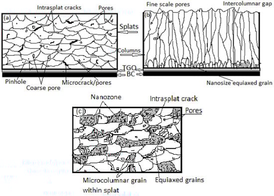
Figure 1.
Schematic illustration of as-deposited YSZ microstructures of (a) APS micro (conventional) TBC. (b) EBPVD-processed TBC and (c) APS-nanostructured TBC. The essential features and various defects are displayed and labeled. Two layers (BC and TC) of the TBC arrangement are shown for (a,b) with a TGO layer in between, while only the top layer structure is shown for (c).

Figure 2.
(a–d). SEM image of conventional 2-layer APS TBC displaying the structural layer arrangements of the substrate (S), BC, TC and TGO growth profile at the BC–TC interface after thermal cycling; (a) 10 cycles (b) 100 cycles (c) 430 cycles and (d) at failure around 1425 cycles [32]. Additionally, the thickness of different layers, TGO measurements and cracking around TGO are also evident.
Recently, a good number of potential advanced TBC materials have been proposed such as pyrochlore-structured La2Zr2O7, fluorite-structured La2Ce2O7, magnetoplumbite-type LnMgAl11O19 (Ln: La, Gd, Nd et al.) and perovskite-type BaZrO3 or SrZrO3 [17,18,19,20,21,22,23,24,25]. Novel ceramics like gadolinium zirconate (GdZ, Gd2Zr2O7) are promising candidates because of lower thermal conductivity, better sintering ability, higher melting point and phase stability. Despite these attractive properties, GdZ with a pyrochlore structure has a lower fracture toughness value of around 1 MPa·m1/2 as compared to that of YSZ (4 MPa·m1/2) and exhibits poor thermal cyclic durability [26,27,28]. Lanthanum zirconate (LaZ, La2Zr2O7) is another pyrochlore ceramic material consisting of the ZrO6 octahedra and La3+ ions at vacancies at the La3+, Zr4+ and O2− [29]. LaZ has high sintering resistance up to its melting point. The elastic modulus of LaZ is around 175 GPa. Low thermal expansion coefficient and poor toughness are the main factors that contribute to lower thermal cycling life. The thermal cycling life of GdZ and LaZ can be improved by incorporating a multi-layer system. The concept of the functionally graded material (FGM) has been well researched over the past decade to substitute for conventional 2-layer TBCs [28,29,30,31,32]. Besides FGMs, advancements with innovative concepts have progressed as an alternative solution to conventional APS TBC processing such as segmented crack coating [33] and suspension precursor coatings [34]. In hybrid-type multilayer TBC architectures, combinations of YSZ with pyrochlore LaZ and GdZ structures have shown promising results. LaZ coating exhibits a better bond coat oxidation resistance than YSZ. They also provide an effective protection from calcium magnesium alumino silicate (CMAS) attack and volcanic ash [29].
A different processing route, namely nanostructuring of standard TBC materials, has generated tremendous interests in industry and academia recently. Nanostructured thermal barrier coatings (Ntbc) have exhibited superior thermal insulation effect, strain compliance, low thermal conductivity and good thermomechanical properties over conventional TBCs (Ctbc) [17,35,36,37,38,39,40]. Nanotechnology has been successfully applied to modify the microstructure with porosity control in 7%–8% YSZ TBC. A large number of controlling features are associated with the behavior of plasma-sprayed TBC systems, namely porosity (volume, micro- and nano size), microcracks (size, morphology), voids and discontinuities, and grain size. A bimodal structure with a controlled porosity level is derived in plasma-sprayed Ntbc from the partial melting of agglomerated nanostructured particles [36]. The bimodal distribution of the mechanical properties results from a bimodal microstructure in Ntbc. A number of striking and beneficial differences can be achieved in Ntbc with respect to microstructures, physical, mechanical and thermo-mechanical properties, and durability as compared to those exhibited by Ctbc. The present work is a comprehensive review of the current state of research progress and development with nanostructured thermal barrier coatings (Ntbc) and remaining challenges. A comparative and critical analysis of the microstructures, including defects and a wide range of properties, aims to address the differences in damage and failure mechanisms between Ntbc and Ctbc systems. The work is confined to 6–8 wt.% YSZ TBC system, though nanostructuring effects in other functional coating and functionally graded systems are reported in the literature.
2. TBC Systems
The two-layered TBC system has remained the most-researched and most-popular system in power industries over the past few decades. This system is designed with an intermetallic bond coat (BC) layer with composition of MCrAlY (M being Ni, Cr and/or Co) in between the top coat (TC) and the metallic substrate, as illustrated in Figure 1 and Figure 2. MCrAlY overlay coating is also applied in other coating types, such as aluminized, Pt- modified aluminized and Pt-diffusion coatings. However, this review work focuses on MCrAlY- 6%–8% YSZ coating system only. R&D for a new generation of TBCs exhibiting improved performance in terms of insulation effects, durability and reliability has always remained a challenge, as traditional TBCs cannot always meet ever-increasing industrial demand. TBCs with low thermal conductivity, high thermal stability, excellent mechanical properties and longer life call for more in-depth research.
2.1. TBC Requirements
Key requirements in TBCs that form the basis of performance assessment are listed here. The comparative analysis and discussions in the following sections will be based on these parameters to comprehend the improvements and shortcomings in Ntbc and Ctbc systems [25,26,27,28,29,30,31,32,33,34,35,36,37,38,39,40,41,42].
- (1)
- low thermal conductivity
- (2)
- strong phase stability
- (3)
- high resistance to sintering
- (4)
- ability to operate in an oxidizing environment and resistance to oxidation
- (5)
- resistance to thermal cycling and thermal shock
- (6)
- chemical compatibility with the underlying metal and TGO
- (7)
- high-temperature corrosion resistance
- (8)
- strain compliance
- (9)
- ability to reflect radiant heat from the hot gas
- (10)
- longer durability
- (11)
- higher adhesive strength and thermal insulation [42,43,44,45].
2.2. TBC Processing
A number of methods are developed to process conventional TBC and the major techniques include atmospheric plasma spraying (APS), electron beam-physical vapor deposition (EB-PVD), plasma spraying-physical vapor deposition (PS-PVD) and liquid feedstock plasma spray (LFPS). LFPS involves the deposition of ultrafine droplets of suspensions or solution precursors (typically nano- to sub-micron size) and permits the production of coatings with unique microstructures. Suspension plasma spraying (SPS) and solution precursor plasma spraying (SPPS) are two main variants of LFPS [41,42,43,44].
The APS process involves the injection of a powder into a plasma jet released by a plasma torch. Powders get accelerated, heated and melted inside the plasma jet and finally impacted onto the substrate. The sudden deceleration of the droplets causes pressure to build-up and forces the liquid to flow laterally. A lamellar microstructure is obtained by stacking splats during deposition, as illustrated schematically in Figure 1a. In the EB-PVD process, a high-energy electron beam melts and evaporates feedstock in a vacuum chamber, and the vapor then deposits onto a preheated substrate. Due to the vapor phase condensation and shadowing effect, columnar, quasi-single-crystal structured TBCs are formed [44]. The EBPVD microstructure is schematically represented in Figure 1b. The APS process enjoys great popularity due to its simplicity, low cost and high efficiency. Major differences in structure and characteristics of Ctbc processed by two most-popular methods, APS and EBPVD, are listed in Table 1. The performance of nanostructured TBC is discussed in later sections in reference to Table 1. APS-treated nano and conventional TBCs will remain at the center of all discussions and comparisons. As micron-sized feedstock is commonly used in conventional TBC, it is also referred as micron TBC as opposed to nano TBC. For clarifications, Figure 1 and Figure 2 display typical microstructures of different classes of 2-layer TBCs as explained earlier. Figure 1a–c shows the schematics highlighting all essential features, while Figure 2 shows the SEM images.

Table 1.
Key characteristics of APS- and EBPVD-processed TBC systems [19,20,21,22,23,41,42,43,44,45,46,47,48,49,50,51,52,53].
3. Nanostructured TBC
Nanostructuring effects in materials become significant with grain sizes less than 100 nanometers (nm) and are present in at least one orientation. The effects tend to exhibit unusual properties enhancing performance as compared to micron-size grain structured materials [54,55,56,57,58,59,60,61]. Nanoceramics demonstrated higher hardness and fracture toughness along with lower ductility and elastic modulus when compared to conventional ones. The last two decades have witnessed tremendous interests in the applications of nanostructuring technique in the areas of materials surface and coating. Numerous systematic studies have been undertaken to qualify and quantify the beneficial effects of nanostructured coatings over their conventional counterparts [57,58,59,60,61,62,63,64,65,66,67]. Special interests developed in the area of thermal barrier coatings in recent time to achieve superior performance in terms of thermal insulation, durability, strength and toughness than what are exhibited by conventional-grade TBC.
Nano-Processing
Two challenges were initially encountered in developing nanostructured TBCs deploying the conventional APS technique. The first issue was with the use of nano-size feedstock powders. Due to the low mass and high specific area of powders, inadequate inertia prevented them from being carried away with the plasma stream and deposited over the substrate. The nano-powder needs to be pre-synthesized to micron-sized agglomerates by spray-drying and partially sintering into micron-sized particles [12,59,60,61,62,63]. Secondly, in order to maintain the nanoscale effects in the coating, the conventional feedstock melting and solidification of droplets on substrate needed the modification of the APS process. The partial melting of the agglomerated particles by controlling the spray processing allows a bimodal coating structure in the as-sprayed condition. The coating results in a mixed bimodal structure consisting of micron-sized columnar grains and unmelted nanogranules [63,64]. The physical characteristics and thermomechanical response of the nanocoatings can be suitably modified by controlling the structure i.e., the size and distribution of the fully melted and resolidified micro region and partially melted nano regions [12]. In other words, during coating formation, the spray deposition of fully and partially molten particles proceeds and is followed by lateral spread, solidification and fast cooling [64,65,66]. Fully molten particle agglomerates give rise to lamellar shape (or lamellar zones), while semi-molten particles preserve the nanostructure (or nanozones). The density and grain size of the powders, in combination with the controlled spraying variables, determine the quality of the nanostructured coating.
The overall performance of TBC also depends on the BC quality, and it was reported earlier that the nanostructured cold-plasma-sprayed BC facilitates the formation of uniform oxide growth on its top [62,65,66]. Likewise, the relatively low elastic properties of Ntbc accommodate large strain for better stability and longer life. The bimodal features of YSZ partially stabilized zirconia nano-coatings with randomly distributed ummelted nano-particles as discussed offer better thermal insulation, reduced thermal conductivity, higher thermal expansion coefficients and thermal cycling life as compared to conventional TBCs [12,22,35,65,66,67,68,69,70,71,72,73,74,75,76,77]. In order to achieve significant nano-structuring effects in TBC, a wide distribution of nano-feedstock powder sizes offers a higher proportion of nano-zones. The following sections focus on a comparative analysis of Ntbc and Ctbc systems, considering a wide spectrum of characteristics, namely properties, microstructure, defects, sintering behavior, damage evolution, failure mechanism(s) and lifetime.
4. Microstructure
A great deal of studies devoted to microstructures in TBCs encompass its evolution, features and control. TBC performance is dictated by its properties, which largely depend on the underlying microstructure associated with various defects. A comparative analysis of microstructures in differently treated conditions is made in this section for both Ntbc and Ctbc systems. However, the Ntbc microstructure is discussed in greater details than the Ctbc structure. Significant microstructural features for the analysis and their measurements include
- (a)
- phase composition of nanostructured zirconia powder as well as coatings measured by X-ray diffractometer
- (b)
- morphology and the microstructure of powder feedstock and as-sprayed YSZ coatings measured by SEM.
- (c)
- area fraction of molten and semi-molten areas and distribution obtained by image analysis of SEM images.
In TBCs, other microstructural features and effects of significance include porosity, microcracking, segmentation, residual stress control and post-spray thermal treatment [78,79,80,81,82,83,84,85,86,87,88].
4.1. Ctbc Microstructure
Ctbc 8YSZ coating microstructure is mainly composed of lamellar microstructure following the solidification of molten feedstock. In addition, Ctbc contains coarse cracks and pores. Essentially, the extent of melting in 8YSZ feedstocks is full and sufficient because of higher power, while melting is only partial in nanostructured 8YSZ feedstock. Conventional 8YSZ coatings can be regarded as fully molten lamellae, while nanostructured 8YSZ coatings demonstrate bi-modal microstructure [80]. A SEM study confirms that horizontal cracks in the form of a typical splat-on-splat structure characteristic of APS were observed in Ctbc [86]. In contrast, many more pinholes and microcracks can be observed in the conventional YSZ coating after air plasma spraying. In Ctbc, coarse porosities evolve from the incomplete melting of particles, pores arising out of the flattening of splats, gas entrapment and large pores associated with lamellar micro cracking.
4.2. Bimodal Ntbc
The microstructural features of Ntbc and their characteristics are first discussed. Nanostructured YSZ TBC is characterized by a bimodal microstructure as mentioned in an earlier section. The major components of as-sprayed microstructures of Ntbc by air plasma spray (APS) comprised [3,12,56,70,78,80]:
- (i)
- Completely molten and resolidified YSZ particles with microcolumnar grain structure (matrix);
- (ii)
- Partially molten porous nano size YSZ agglomerates (nanozones) that were embedded in the coating matrix;
- (iii)
- A small fraction of unmelted particles.
Other features of bimodal microstructure include splats, microcracks and high-volume spheroidal pores. The nanozones are formed from porous nanostructured feedstock, which is partially melted (or unmelted) during plasma travel and deposition in the APS process. The structure is a porous one and offers excellent thermal insulation effect [12,56,60,61,62]. Partial melting helps developing porosities due to cluster agglomeration that acts as a barrier against heat transfer from the plasma jet to the inner core of the feedstock [12,81,82,83]. The porosity in the coating plays a marked role in controlling properties, and the porosity content in TBC depends on the extent of melting during spray deposition. Porosity is also present in the nanostructured bond coat. Additionally, the as-sprayed coating of Ntbc also contains a thin and uniform layer of alumina oxide. Nano feedstock has a smooth surface compared to conventional feedstock, which accounts for good flowability. In Ntbc, nano-zones are porous, and the feedstock is composed of nano-agglomeration. The internal structure of nanostructured 8YSZ feedstocks is compact, while it is porous for conventional 8YSZ feedstocks. [80]. SEM images confirmed a relatively dense structure with a majority of the cracks oriented in the vertical direction in the as-sprayed microstructures of nano TBC [12,81,82,83,84,86]. Narrow particle-size distribution in Ntbc is attributed to a denser structure.
4.2.1. Trimodal Structure
As opposed to the bimodal structure in Ntbc, the Ntbc microstructure has been described as trimodal to be more specific. [58,67,85]. The trimodal distribution consists of (a) laminar layers with columnar grains that are surrounded by (b) the semi-melted parts of the nanostructured powders and (c) some equiaxed grains at splat boundaries due to uniform nucleation (micro- and nanosized grains). Columnar grains form at splat boundaries due to heterogeneous nucleation and tend to be oriented along the direction of grain growth. Typically, columnar grain size ranges over 50 to 300 nm [80]. Nanostructured YSZ coating includes fewer pores, voids and microcracks because of the compactness of the nanostructure. In the nanostructured YSZ coating, the inhomogeneities and interconnected pores are relatively fewer and the existence of nanozones (containing nanoporosities and nanoparticles) in the nano-YSZ coating act as a strong barrier for oxygen infiltration into the TBC at elevated temperatures. Fewer pinholes or microcracks in the YSZ layer will result in lower oxygen penetration into TC at elevated temperatures [65,66,85].
4.2.2. Nanozone
Nanozones play a very active role in the overall improved performance of Ntbc. Nanozones refer to unmelted/partially melted powders within a coating. The structure of this zone resembles primary agglomerated nanostructured YSZ powders. This zone is filled with a large number of nano grains. Nanozones are able to arrest crack generation and propagations into the molten phase. Microcracking, as promoted by the thermal stress due to thermal expansion mismatch, is detrimental for any material. Nanozones help in enhancing fracture toughness and in turn offer resistance to thermal shock and more durability [36,59,86]. A controlled degree of the melting of nanostructured feedback controls the extent of nanozones in Ntbc and the porosity level. The increased compliance capability of the nanostructured coating and consequently, its better performance during thermal exposure is because of the extra source of porosity associated with the nanozones [84]. The percentage of nanozones embedded in the coating structure ranges from 20%–35%, with the majority of reports citing closer to 25% [12,55,69]. A high number of nanozones % (30–40) is recommended for abradable coatings, while a lower portion of nanozone (20%) content is preferable for TBC with low thermal conductivity, high structural integrity and resistance to the infiltration of oxygen and molten salts in severe working environments. The nanostructured areas with a low sintering rate is preferred to counteract the high-temperature densification of YSZ coatings [59].
4.2.3. Controlled Melting
The two most influential thermal spray parameters capable of controlling the melting process and the resulting nano-micro-structures in TBC processing are described earlier as plasma power and spray distance. The discussion was in the context of influencing elastic modulus and hardness in TBCs. The degree of melting is strongly related to the temperature distribution in the plasma jet and heat transfer to the porous agglomerates. Bimodal or trimodal structures of Ntbc coatings are composed of well-melted splats and partially melted/unmelted nanostructured areas [36]. The nanostructured areas are composed of loosely bound nanostructured particles with a size of around 100 nm. During processing, the hot plasma gas penetrates inside the agglomerated particles of the powder feedstock, melting their surface, while the core remains unmelted. The particle size is able to maintain nano range without grain growth because of the fast quenching of the splats, short travel time in the plasma jet and little heat transfer due to porosity. An increase of plasma current promoted the increase of the particle temperature, improving the melting degree and the density of the coatings. At constant spraying distance, better melting of particle agglomerates occurs with the plasma current increasing and so the nanozone areas and this effect promotes denser nanostructured coatings. On the other hand, at constant plasma power and with increasing spray distance, more melting can be expected because of longer travel time in the plasma jet, resulting in higher deposition efficiency and coating thickness [36]. The extent of melting finally determines the distribution of nanostructured areas, density and mechanical integrity of the coating. An optimum combination of spray parameters is essential, especially with respect to plasma current and torch-to-substrate distance.
4.2.4. Submicron vs. Nano Coating
The effects of particle-size distribution on the microstructural evolution in Ntbc, considering a submicron grain size of 150 to 580 nm and a nano grain size of 20 to 60 nm, was addressed by Y. Wang et al. [54]. The as-sprayed microstructure of the submicron coating is composed of lamellae structure and columnar grains within lamellas, inter-splat pores and cracks. The nanocoating microstructure on the other hand revealed loosely distributed unmelted particles maintaining the nanostructure of the feedstock in the recrystallization zone (splats). The fraction of unmelted particles in the nanocoating was rather small and around 13.3%, compared to the melted and resolidified columnar grains. The porosity content in both the submicron and nano coatings were found to be nearly similar, though the microcrack % was slightly higher. The submicron coating formed was dense and irregular. The as-sprayed nanostructured TBC microstructure with zirconia powders of 15 nm on stainless steel substrate showed molten (around 30%) and non-molten phases (around 70%). The non-molten phase appeared to be very loose, and the micro-pores between the micro-particles have sizes similar to those of nano-particles. The TEM image presents the grain size of the non-molten phase coating consisting of fine grains with sizes ranging mainly from 30 to 45 nm [68].
4.3. Porosity
Porosity, unmelted or partially melted particles and cracks are considered the intrinsic defects in Ntbc systems. The evolution of the porosity in the microstructure of TBCs is a natural phenomenon, and their size, shape and distribution play a significant role in controlling the behavior of the coatings. Porosity can have both beneficial and detrimental effects on performance, depending on the functionality of a TBC. The porosity level in microstructures is analyzed from SEM images by image analysis software. Porosities in TBCs processed under thermal spraying can be grouped as fine, with a size range of a hundred nanometers, and as coarse, with a size range of tens of microns [17]. However, in a nanostructured coating, besides these porosities, pores also occur inside nanozones. The trimodal distribution of pores during exposure at high temperature of TBCs helps increase durability under thermal shock and decrease the thermal diffusivity and elastic modulus of TBCs [12,17]. The volume % distribution of porosity in sintered Ntbc structure is displayed in Figure 3. A range of 10% to 25% porosity can be expected in sintered Ntbc that can exert a large influence on its behavior. The trend becomes steady within 50 h of thermal exposure.
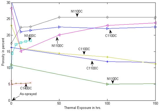
Figure 3.
Sintering effects on porosity level in Ctbc and Ntbc. Data collected from published sources are plotted only up to 150 h of sintering to highlight the trend [12,17,69,87]. N and C stand for Ntbc and Ctbc. The sintering temperature in °C is shown for each line.
4.4. Influence of Thermal Exposure
Limited studies on the sintering effect on porosity demonstrated that the densification process reduces the porosity level significantly due to sintering in both TBCs. Figure 3 demonstrates the trend in changing the porosity level in both TBCs because of the sintering effect. A not very orderly or consistent trend may be noticed. However, a generic tend shows that porosity tends to drop initially at a fast rate and then increase later at a much slower rate. This effect tends to increase the EM.
Thermal conductivity affects the strain tolerance behavior as discussed before [14]. In Ctbc, the drop in the porosity level reaches around 30% (from 16.2 to 11.4) over the first 200 h of thermal exposure at 1100 °C, followed by around a 10% drop over the next 400 h to a value of 10.2. In Ntbc, the densification kinetics is very high in the beginning, with a 54% drop in the porosity level within the first 100 h of sintering (10.9% to 5% porosity); thereafter the increase was small [14]. The densification response of two zones, i.e., nanozones and resolidified splats during sintering, appear to be quite different. Nanozones experience higher shrinkage during the sintering process and tend to open up pores and also increase the size of crack-like discontinuities present. The behavior of Ntbc towards the sintering due to thermal exposure is different from the Ctbc, as the porosity level is reduced first and then enhanced slightly. A continuous increase in the porosity level in nanostructured YSZ coatings is demonstrated when aged at 1400 °C. A comparison also revealed that the porosity content in Ntbc is 1.8 times larger than that of a conventional YSZ coating after 20 h of aging [10]. After 20 h at 1400 °C, the coarse porosity level of the nanostructured coating was 3.5 times higher than that of the conventional one.
5. Thermo-Mechanical Properties
A wide variety of factors involving thermal spray processing conditions, nano-micro feedstock powders and size distributions result in a wide range of microstructures and properties in TBCs [68]. The thermal and mechanical responses exhibited by both Ntbc and Ctbc microstructures under the influence of different heat treatments and thermal exposures are presented, analyzed and discussed in following sections.
5.1. Elastic Modulus and Hardness
Elastic modulus (EM) is of prime significance in the design of TBC system for hot turbine section components. For comparison and contrast, EM data for Ntbc and Ctbc systems are compiled from several sources, and Figure 4 displays the changes in EM as a function of thermal exposure. A few different trends, wide scattering and several inconsistencies in EM are observed and discussed here. The trend and the changes in general in EM of as-sprayed TBCs can be broadly divided into two stages, firstly, a short duration within 10 to 20 h when a steep hike in El takes place, and, secondly, a long period beyond the first stage when EM changes at a much slower rate and/or becomes nearly steady and constant. The first stage results from the accelerated sintering effect when large microstructural changes occur due to high driving force. In the second stage, the sintering effects gradually decline with time. However, in the second stage, various lines show positive, negative and first-positive-followed-by-negative slopes, as may be seen in Figure 4. Indentation measurements confirmed that the nanostructuring effects are maintained in the first stage and that a further increase in EM is caused by the densification of the structures in Ntbc [68]. In general, the Ntbc exhibits higher EM than Ctbc, though the opposite behavior may also be seen. Two lines showing negative slopes over 200 h are presented as straight lines due to a lack of data and may be somewhat misleading [20]. But there is a loss in EM compared to as-sprayed values due to sintering. However, a trend in EM showing a positive slope initially, followed by a negative slope, appears to be more logical for both TBC systems. The peak value of EM is closely associated with the saturated nano-micro-structured conditions. The changes in the values of El have been justified relating to various microstructural features.
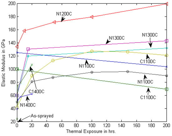
Figure 4.
Elastic modulus for thermally exposed Ctbc and Ntbc. Data collected from published sources are plotted only up to 200 h. of sintering to highlight the trend [12,20,55,68]. N and C stand for Ntbc and Ctbc. The sintering temperature in °C is shown for each line. No clear trend for the sintering temperature is observed.
A different measurement method based on density, porosity and elastic wave propagation through TBC indicated much lower EM for Ntbc than the same for Ctbc [12], as shown in Figure 4. Lower density and wave velocity for Ntbc justifies a lower value after 20 h of thermal exposure at 1400 °C. There are a number of interacting microstructural features that control the stiffness and hardness and that are responsible for higher oxidation resistance in Ntbc. These are TGO growth and spinel formation, increased density of microcracks, pore healing, densification, interlocking between splats [20]. Tendency to spinel formation in Ntbc is much lower than Ctbc.
Hardness (Hd) measurements demonstrated a sharp increase in the first stage of the sintering of Ntbc at 1200 °C, as EM shows around 40% increase within 10 h of thermal cycling, followed by additional 20% increase in the second stage over 190 h [68]. The same study indicated around 100% increase in EM in 7 wt.% Ntbc within 10 h, followed by only around 10% additional increase in next 500 h of thermal cycling at 1200 °C [55]. This behavior is shown in Figure 4. Both Hd. and EM in Ntbc results from the contributions of two phases, namely molten and non-/semi-molten phases. However, the net contribution of the non-/semi-molten part is relatively lower, as their proportion is lower. In addition, the EM and Hd. values of this phase are lower than the EM and Hd. Of non-semi molten phase as shown in Table 2. EM and Hd. data obtained for Ntbc show a bimodal distribution in their weibull plots, indicating the presence of two phases that are described as molten and non-molten. However, the weibull distribution is also lost due to healing effects with continued exposure [68].
Table 2.
Properties and characteristics of various zones in microstructures [36,65].
5.1.1. Spray Parameters
Effects of spraying parameters on the nanomechanical properties are of practical importance. Spraying distance and plasma current are considered to be most influential during processing [36,65]. Mechanical properties tend to increase with increasing the plasma current and the spraying distance. Increasing the plasma current at constant spraying distance results in an average increase in EM is reported to be 9% and 30%, and the increase in hardness is around 13% and 60% as the structural transition occurs from nanoscale to microscale. The influence of the spraying distance is relatively less prominent. At a constant current value, for increasing values of torch–substrate distance, an average increase of 4% and 7% for EM and 3% and 34% for Hd. was reported due to the nanoscale-to-microscale change. Additionally, in the bimodal structure, the melted phase is characterized by higher stiffness and hardness in comparison with the partially melted area. The uncertainties associated with the values of the EM and Hd. of two Ntbc lie with the spray conditions. Additional uncertainty in EM and Hd. arises from the complexity of nano-structures, as shown in Table 2. The mechanical properties of two zones comprising the Ntbc involve a wide scattering in data, especially in the partially melted zone. The EM and Hd. values of the partially melted zone are substantially lower than the values for the melted/resolidified zone.
An increase of plasma power and spraying distance was able to produce denser coatings, with lower content of embedded nanostructures, which exhibited higher elastic modulus and hardness, as well as a lower wear rate [36].
5.1.2. Bimodal Distribution
EM and Hd. data for Ntbc follows a bimodal distribution, as represented by a weibull distribution with shape and scale parameters [88]. This is reported to be both for the melted and unmelted zones in the bimodal structure. However, EM and Hd. tend to exhibit lower values with increases in the indentation load, as a higher load involves greater volume with microstructural defects. The distribution and the scale-shape coefficients are useful for the prediction of properties. Lower values of Hd. or EM reflects the mechanical behavior of the partially molten/unmelted zone, as this zone is characterized by lower values and greater data scattering, as may be seen from Table 2. At a constant spray distance, increases in the plasma current increases the slope of the regression line with the increase of the melted zone of the sprayed feedstock. At a constant current level, the increase of the spray distance produces a different trend, which is consistent with the area fractions of the nanostructured area.
5.2. Bonding Strength
Bonding strength (BS) in nanocrystalline TBC (Ntbc) is reported to be higher than the micro-columnar grain TBC. Average bonding strength values are reported to be 42 ± 4 and 37 ± 3 MPa for Ntbc and Ctbc, respectively, from one source [20], while these are 42.05 and 23.65 MPa as reported by another source [27]. The Ntbc data from two sources are consistent, though there is a large difference for Ctbc. This difference has been attributed to the presence and distribution of cracks and their propagation path through the coating microstructure [59]. Cracks tend to find an easy and weak path to travel along splat boundaries in both the microstructures. However, in the Ntbc system, the splat boundaries are filled with nonmolten particles and nanozones that offer resistance to crack arrest and deflection. In the other case, in the absence of these obstacles, resistance is less in Ctbc and so is the bonding strength [89,90,91]. Crack propagation in bimodal structure is prevented by splat boundaries and unmelted particles, thereby improving the bonding strength. It is worth noting here that bonding strength in nanocrystalline titania coating is reported to be 2.4 times higher and 1.8 times higher for nanocrystalline alumina-titania coating as compared to their conventional counterparts. Inconsistency in BS values measured by ASTM tension method may be noticed as the measured bonding strength values is reported to be 8.9 ± 0.6 MPa and 6.7 ± 0.8 MPa, respectively, for micro-TBC (Ctbc) and nano-TBC. Coating-substrate interface cracking damage in the micron-coating is found to be dominant, while it is the cracking of the porous microstructure in the nano-coating. The lower values of BS here may be explained by the measurement method and the absence of a bond coat. Both coatings were deposited directly onto Ni3Al substrates by the APS method [91].
5.3. Thermal Behavior
5.3.1. Diffusivity, Conductivity and Expansion Coefficient
Thermal diffusivity (TD), conductivity and the thermal expansion coefficient (TEC) are important thermo-physical properties for TBC systems. The thermal insulation capability of TBCs is directly related to thermal conductivity and TD, while TEC mismatch between the substrate and TC is responsible for residual stress generation within TBCs. Thermal diffusivity reflects the heat-transfer ability of a material and high diffusivity means rapid heat conduction from the hot to the cold end. Thermal conductivity is related through density and the specific heat of a material. In as-sprayed state as well as the heat-treated structure, the diffusivity of Ctbc is around 60% higher than that of Ntbc [66,67]. Lower thermal diffusivity in Ntbc may be attributed to the increase of grain boundaries, micro pores and defective crystal structure [12,92]. Smaller micropores prevent an increase in thermal diffusivity because of greater interfaces and thus exhibi more effects on phonon scattering. The bimodal structures of Ntbc undergo a differential sintering process between the matrix and nanozones and prevent an increase in thermal diffusivity and EM over time.
All three properties, TD, thermal conductivity and TEC are directly linked to the service performance and life of TBCs. Nanostructured 8YSZ coatings have demonstrated lower thermal conductivity than conventional TBCs, especially for a temperature range higher than 1000 °C, as may be seen from Table 3. Moreover, nanostructured 8YSZ coatings have shown better thermal insulation capability, compared to conventional 8YSZ coatings when both are processed by APS. These thermo-physical properties are affected by the coating microstructures, which, in turn, are influenced by thermal spraying parameters and characteristics of feedstock [92,93]. Table 3 presents comparative data for three important thermal properties, namely thermal conductivity, TD and TEC and for two TBCs and for two temperatures (RT and 1200 °C). Both TBCs are fabricated with t’ YSZ phase.
Table 3.
Experimental data for Ntbc and Ctbc fabricated with t′ YSZ phase for two temperatures [92,93].
Consistently, thermal diffusivity values of both nanostructured and conventional 8YSZ coatings are significantly lower at RT than the values measured at 1200 °C. At high temperature, the mode of heat conduction is mainly due to lattice vibration, i.e., phonon conduction. Moreover, TD and thermal conductivity for Ntbc is substantially smaller than Ctbc at both temperatures, and this has great merit in favor of Ntbc for any thermal insulation applications as TBC. In fact, there are many factors, such as grain size, grain boundary density and defects, to explain the lower thermal conductivity in Ntbc [92,93]. The low thermal conductivity of TBCs is largely due to phonon scattering with a mean spacing less than the intrinsic mean free path. In Ntbc, nano-sized grains additionally limit the mean free path of normal phonon modes, further lowering the thermal conductivity. Pores and cracks of different shapes and sizes in TBCs contribute immensely by impeding the heat flux by phonon scattering. Thermal conductivity almost drops by 60% due to this impact. The presence of such defects also cause a drop in TBC stiffness by 50% and lower residual stress to accommodate larger strain [7,94]. In addition, porosity also has a big impact on conductivity. The lower bulk density of the nanocrystalline YSZ TBC with more porosity also contributes to lower conductivity than TC in the Ctbc system. The thermal aging of all TBCs tends to enhance thermal conductivity irrespective of coating processing, and EBPVD coating offers more resistance against the increase in thermal conductivity. The TC of APS coating increases by 1.6 times after thermal aging at 1000 °C for 1000 h [95]. The thermal expansion coefficients are nearly similar for both room temperature and at 1200 °C for Ntbc and Ctbc, unlike TD and thermal conductivity.
5.3.2. Thermal Insulation Capacity
A good number of studies have demonstrated that Ntbc exhibits higher thermal insulation capacity compared to Ctbc. The presence of bimodal structure/nano-zones is primarily responsible for superior thermal insulation capability [70]. Other factors, such as lower thermal diffusivity and lower thermal conductivity in Ntbc as discussed earlier, support this desired capability in Ntbc [66,67]. Defect characteristics, especially the porosity, play a significant role in improved insulation in Ntbc. Finite element simulations of heat transfer under different pore shape, size, orientation and volume fraction in the APS TBC system demonstrated the significant roles of the porous structure [96,97,98,99]. The effective thermal conductivity in Ntbc is significantly lower and contributes to higher thermal insulation. Thermal insulation capacity was measured directly on intermetallic Ni3Al without BC for nano and micro TBCs of 150 microns thickness.
The temperature drop (∆T) across the coatings was measured to be 98 and 65 °C, respectively, for nano and micro TBCs at furnace temperature of 1200 °C [91]. A 50% higher capacity in Ntbc is attributed to a bimodal structure that consists of columnar grains and nanozones with intrinsic porosity. Partially molten nanozones help with reducing thermal conductivity and inducing horizontal microcracks to limit heat transfer [12,90]. Lavasani et al. measured the insulation capacity to be around 28 ± 4 and 80 ± 4 °C, respectively, for Ctbc and Ntbc in their as-sprayed conditions and at a furnace temperature of 1100 °C. TC and BC thickness in both cases are kept at around 350–400 microns and 100–150 microns. Effective and higher insulation capacity in Ntbc is attributed to a smaller grain size and lower porosity. Both of these factors largely contribute to phonon scattering and reduce the heat-conduction effects. However, the insulation effects for both Ntbc and Ctbc tend to decline after thermal exposure for 150 h, as ∆T factors are around 53 ± 5 and 13 ± 3 °C [87]. Differential sintering effects in two coating structures makes major differences. In Ntbc, nano pores are healed up to micro sizes, and the sintering rate in nanozones is higher than in splat regions, causing differences in insulation capacity.
5.4. Thermal Shock Resistance (TSR)
Thermal shock resistance is the property of a material that makes it resistant to sudden and rapid temperature changes. Materials having high thermal shock resistance properties are able to withstand wide temperature gradients. TBCs are subjected to thermal gradients arising out of a number of sources during service. Major sources may include active cooling from back side internal cooling, engine shut down causing faster cooling of the top surface, nonuniform heating and cooling, etc. [2]. Normally TSR behavior is measured by heating TBCs to a high temperature in a furnace, holding for 5–10 min and then dropping them in water to quench them. The steps are repeated or cycled until any damage at the surface or failure noticed. The number of repeated cycles until 10% to 20% spallation of the top surface is a measure of TSR. The number of cycles to failures in Ntbc has been observed to be 2 to 4 times lower than the same observed for Ctbc [12]. In one investigation, the number of cycles measured were 261 and 170 at failure, respectively, for conventional and nanoscale TBCs. A possible reason for the lower TSR in Ntbc could be the greater thermal effects leading to the accelerated instability of nanostructures. Nano grains and nanoparticles tend to become thermodynamically stable at higher temperature. Nano grains having lower activation energy grow to micron-sized grains, resulting in volume-contraction-assisted stress generation, which facilitates cracking in Ntbc. The other factor for smaller TSR in Ntbc is due to the thermal stress distributions at different zones being different. In the conventional type, this process is delayed, causing the enhancement of TSR [13,54,96,97]. As a result of a high densification rate at high temperature, larger voids tend to form in Ntbc to lower the thermal shock life. However, very limited research work on this important aspect has been documented until now, and contradictory results are also reported in the literatures without a proper explanations. More in-depth research on TSR is required on both crystalline and conventional thermal barrier coatings.
5.5. Thermal Fatigue Resistance (TFR)
As opposed to the thermal shock experienced by TBCs discussed in the previous section, TBCs are more likely to encounter thermal fatigue in an aero-propulsion system. TBCs encounter thermal fatigue during operation as temperature transition takes place slowly and repeatedly a large number of times. TBCs are subjected to thermal gradients in a number of ways [2]. Firstly, because of active cooling at the back of the TBC, the gradient is set up along the thickness direction. Secondly, along the surface direction, the gradient occurs due to non-uniformity in the heating–cooling process, in the hot components like combustion chambers. Thirdly, engine shut-off/starting can cause gradients. In addition to the thermal response, mechanical loading also imparts stress gradients across the thickness and cyclic nature of loading. Therefore, the response of TBCs to thermomechanical loading and stress gradients is the most important issue. The thermal cyclic fatigue test is carried out by raising the temperature of TBC to a high temperature (say 1200 °C) and holding it for a fixed period (say 1 h), then cooling to a low temperature (RT or 100 °C) and waiting for 10 min before beginning the next cycle. A pre-determined slow heating and cooling rate is normally adopted in TCF study.
The damage and ultimate failure in TBC systems under thermal fatigue occurs by the spallation of the top ceramic coat, and the resistance is measured by the number of cycles sustained by TBC for certain % (around 20%–30%) of surface spallation. The thermal cycling brings considerable changes in the microstructures in both forms of TBC, i.e., Ntbc and Ctbc because of sintering effects. Significant changes in microstructure that include formation and growth of TGO due to oxidation; changes in the shape, size and number of pores due to healing; crack initiation; growth and coalescences. Horizontal cracks generally form along the interfacial region between the TGO and the YSZ coat, but transverse crack gradually develop with continued sintering effects [5]. With a number of cycles around 700 and higher, cracks eventually spread inside the TGO and the YSZ coat, and a network of cracks form. The network is mainly responsible for delamination when little TBC life is expected. Cracks also form around the surface roughness crest during thermal cycling. The damage developed in the TBC with thermal cycling due to crack networking is also accompanied by a transformation in the microstructure. This eventually extends to the bond coat, top coat and the TGO region.
Between Ntbc and Ctbc, thermal fatigue resistance is reported to be more in Ctbc than in the other. A higher thermal cycle life in Ctbc was justified in terms of microstructure, cracking damage and elastic modulus difference between the two [98]. The average TCF life in Ntbc and Ctbc systems is measured to be around 580 and 1020 cycles, respectively, when the temperatures cycled between 100 and 1100 °C. The spallation damage begins around the edge/corner of the top coat in both systems at different cycles and the cycles are higher for Ctbc. Eventually, the damage spreads to other regions when delamination to spallation occur. The higher TCF resistance in Ctbc is justified with the higher number of cracks, lower crack growth rate and greater tendency to coalesce under the influence of thermal sintering. Adequate research work has not been carried out and documented yet on thermal fatigue resistance behavior in spite of its great practical significance for improved durability. More in-depth and systematic investigations involving the quantitative analysis of the size, shape and numbers of both pores and cracks in relation to the melted and unmelted regions are recommended for both Ntbc and Ctbc. A dense microstructure in high-purity nano TBC exhibits inferior performance during thermal cyclic fatigue tests compared to the standard TBC system, due to its lower strain tolerance [98]. Finite element analysis revealed significantly lower residual stress in both the axial and radial directions in Ntbc, respectively, by 67% and 73%, as compared to Ctbc. [61]. Lower residual stress has been attributed to the increased thermal cyclic stress in Ntbc, as confirmed for three temperatures, namely 1050, 1100 and 1150 °C.
5.6. Wear Resistance
The presence of nanozones in the bimodal structure of nanocrystalline YSZ TBC is primarily responsible for the high wear rate. Component failure mechanism by wear in TBCs has been explained by a combination of brittle fracture and abrasion. Wear degradation in TBCs mostly occurs by delamination and the fragmentation of particles from the surface. The presence of dense nanozones limits these phenomena. The brittle fracture is confined by the crack arrest effect, whereas the abrasive wear is reduced by the wear scars of the nanostructured coating [100]. Moderate wear resistance may be achieved in Ntbc when the nanozone volume is around 20%. Wear resistances in coatings can be achieved with relatively low nanozone volumes. The process parameters need to be suitably controlled to have low volume of nanozones in order to impart wear resistance [101,102].
6. Oxidation Resistance
The direct effect of thermal exposure of TBCs to high temperature is the oxidation when oxygen diffuses through the porous top ceramic coat to react with aluminum in BC and form alumina (Al2O3). The reaction product forms at the interface between the top coat and BC in the form of an additional layer termed the thermal-grown oxide (TGO), as illustrated in Figure 1 and Figure 2. TGO protects BC from degradation by way of further oxidation but creates harm to the TBC system because of generating residual stress and other effects. A small amount of Cr and Co oxides also form, along with alumina [7,98]. As oxidation is one of the main causes of the failure of TBCs, numerous experimental, analytical and computational studies have been undertaken on the conventional 2-layer TBC to understand the growth kinetics of TGO under isothermal and high-temperature cyclic exposures. This section explores the oxidation resistance behavior of Ntbc and Ctbc systems and analyzes the differences in the kinetics of TGO growth. Superior oxidation resistance in Ntbc has been well documented from numerous studies, in comparison to the oxidation behavior of Ctbc. The primary reasons for this include less oxygen diffusion through the nanozones, pores and fine-grained nanostructured YSZ [12,17,20,35]. TGO formation has a profound effect on the local stress development in TBC. There are three main causes for the nature (tensile or compressive), magnitude and distribution of residual stress, namely volume expansion, uneven TGO thickness and roughness due to inhomogeneous oxidation. The residual stress at the BC/TC interface is the most significant controlling factor to initiate damage and its accumulation, which eventually leads to the failure of the TBC by spallation. Among other damages formed due to TGO growth, microcrack formation is the ultimate damage formed at and around two interfaces, namely BC/TGO and TGO/TC in both the TBC systems [55,99,100,101,102,103]. Microcracks grow under the influence of residual stress with oxidation time, and the spallation of TC occurs, limiting the coating life.
6.1. TGO Kinetics
The TGO growth kinetic in TBC has immense influence on the spallation and estimation of life-span. Figure 5 displays the TGO thickness variations in Ntbc and Ctbc under different conditions as compiled from different sources. The data for Ctbc was obtained under thermal cycling at 1080 °C and for two different oxygen levels [32]. All other data collected are for isothermal exposures over different periods. All TGO data points are consistent, and the thickness values increase with the time of exposure. However, two important observations are, firstly, the slope of the lines are steep initially and reduces gradually; secondly, the TGO growth is smaller in Ntbc than the thickness in Ctbc for the same time and/or temperature of exposure. In different words, Ntbc has higher oxidation resistance than the same in Ctbc, as observed by a number of researchers, and the TGO growth kinetics decreases with continued oxidation. The other interesting point to be noted is the relatively lower oxidation kinetics (higher resistance) in compositionally graded TBC systems, as shown by lines 2 and 3 in Figure 5. Oxygen diffusion is restricted due to the presence of additional interfaces in FG systems. Other factors as discussed in this section are also applicable.
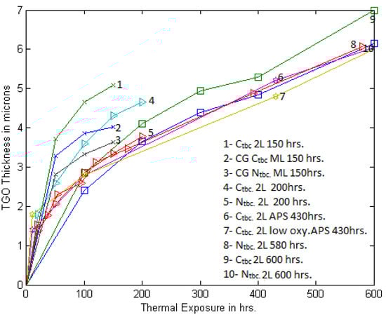
Figure 5.
TGO thickness change in Ntbc and Ctbc under different sintering (oxidation) conditions. L—layer, ML—multilayer, CG—compositionally graded, Low oxy—Oxygen low pressure. Data collected from published sources [17,19,20,32,57].
Nanostructured coatings being denser and packed with fewer pinholes and voids allow limited oxygen diffusion and are primarily responsible for better oxidation resistance than Ctbc. The structural stability of Ntbc is also far better than Ctbc [20,99,100,101,102,103,104]. Oxygen permeation in Ntbc is also controlled by other factors, namely a fine grain structure and finer particles. A continuous, uniform and thinner oxide layer forms in Ntbc, as opposed to the mixed inhomogeneous oxide formation in Ctbc [105]. Levels of Ni(Cr, Al)2O4 (spinel) and NiO on the surface of the Al2O3 layer in nano TBC systems was much lower compared to that of normal TBC systems during thermal exposure at 1150 °C. These two oxides play a detrimental role in causing crack nucleation and growth, reducing the life of the TBC in air [99].
The lower oxidation resistance of Ctbc is primarily responsible for the inhomogeneous distribution of open pores and microcracks and exhibits less adhesion between the top coat and BC. The progressive diffusion of Al in BC towards the interface between BC and TC takes place during oxidation to form TGO, causing Al depletion in the BC reservoir. A study revealed, a drop in wt.% Al from 7.6 (as-sprayed condition, zero cycle) to 4.66 to 3.60 at the lowermost layer of BC after thermal cycling of 1003 and 2010. The oxidation occurred in Ctbc at a temperature of 1010 °C. As the diffusion is a function of the concentration gradient, it is to be noted that, with the time of oxidation, the rate of TGO growth (measured by the TGO thickness) also decreases, as illustrated in Figure 5. Another study confirmed that the spallation of the top coat from BC occurred after 200 h and 260 h of oxidation, respectively, for Ctbc and Ntbc [20]. Figure 5 displays the TGO thickness variations in Ntbc and Ctbc as a function of isothermal oxidation in terms of hours at 1100 °C. Clearly, the extent of oxidation is higher at 600 h than at 200 h in both of the TBC systems. However, in Ctbc, TGO thickness is consistently and uniformly higher than the oxidation in Ntbc [17,20]. Unlike high-purity nano TBC, the observed cracks are of much higher length after 200 cycles compared to the as-sprayed state. A different investigation observed the oxide thickness to be 32% less in Ntbc as compared with the oxidation in Ctbc for the same isothermal oxidation time at 1000 °C. The first 24 h revealed a much faster TGO growth rate that gradually declines, following a parabolic relation. The higher oxidation rate in Ctbc is also attributed to the tendency for spinel formation, as diffusion through chromium is faster than dense alumina [67,99].
A recently published experimental study investigated the TGO growth in plasma-sprayed Ctbc under two environmental conditions, namely (a) in air and (b) in low-pressure oxygen [32]. The as-sprayed samples were vacuum heat-treated for 4 h at 1080 °C prior to thermal cycling. Each cycle consisted of 8–12 min ramping to 1080 °C for 45 min, followed by slow cooling to room temperature. After a desired number of thermal cycles, i.e., 10, 100 and 430, samples were sectioned, mounted and metallographically prepared. TGO thickness was measured using the SEM images of cross-sections by two methods, namely area-based and point-to-point [32]. TGO thickness measurement results under two environmental conditions are displayed in lines 6 and 7 in Figure 5 to compare with others’ results. The data points from different sources match fairly well and for both isothermal and thermal cycling conditions. However, it is worthwhile to mention here that the oxygen availability and pressure level during APS processing do not seem to have any noticeable influence on the oxidation characteristics.
6.2. Empirical Relationship
The TGO growth trend with thermal exposure is the most important parameter in the understanding and modeling of the TBC delamination process. A simplistic representation of the TGO growth is an unambiguous input for any quantitative modeling and for lifetime prediction. The oxidation growth behavior in TBC systems are well-represented by a parabolic relation as Ttgo = kp (t.)n, where kp and n are the oxidation coefficient and exponent; Ttgo is TGO thickness, and t is oxidation time [17,18,19]. A good approximation of n is reported to be 2.5, and values of kp are reported to be 1.977 × 10⁻¹⁷ and 1.6362 × 10⁻¹⁷ m2/s for Ctbc and Ntbc [28]. Keyvani et al. [19] obtained empirical relations for the conventional and nanostructured YSZ TBC exposed at 1100 °C as Ttgo = 0.5107 (t)0.4218 and Ttgo = 0.4217(t)0.4190, respectively.
Thermal exposure is rationalized with respect to time to failure (t/tf), while TGO growth (Ttgo) is found to have a linear relation with thermal cycling when both the parameters are rationalized, as discussed for two environmental conditions [32]. All data points for two classes of APS treatments fall close to each other to be represented by the empirical relation as: Ttgo/Tlayer = m(t/tf) + c. A three-stage TGO growth and parabolic function between the minimum TGO thickness and thermal cycling [30] are also presented where thickness change per cycle (Δh) is given by (h − h0) × Δt/2t, where h0 is the initial TGO thickness, and h is the TGO thickness at time t. Limited TGO data generated from the experimental investigation are plotted in two ways, as displayed in Figure 6a,b. Untreated TGO thickness tend to follow nonlinearity as a function of the time of thermal exposure, as shown in Figure 6a, for both the coatings considered in the work. The data points fit best with 2-degree polynomials for both coatings with R-square values close to one. It may be noted here that the coefficients of the square terms are very small, as may be seen in the fitted equations shown in Figure 6. A different explanation of the trend may also emerge with a closer look of the how the trend is made. It reveals that the first three points (up to 430 cycles) fit linearly, while the last part, i.e., 430, to the failure point of the plot follows a more nonlinear trend.

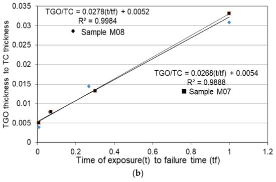
Figure 6.
(a) Nonlinearity trend for TGO thickness vs. time of exposure fitted with 2-degree polynomials; (b) linearity trend with parameterized data for TGO thickness and thermal exposure for both samples, M07 and M08 [32]. Sample designations refer to oxidation under low-oxygen partial pressure (pressure of about 0.27 Pa) and atmospheric-pressure conditions respectively.
7. Degradation and Failure Mode
TBCs experience the most-severe working environments in gas turbine engine operations in terms of temperature and its gradient, nonuniformity in pressure and heating, oxidizing condition, hot corrosion, mechanical loadings, particle impact, etc. Early damages develop in TBCs and grow with service time, leading to eventual failure. The durability of TBCs is of great concern, and therefore, a proper assessment of the damage(s) and failure mechanisms involved in failures are of great importance. A great deal of experimental and simulation research on damage evolution and failure for Ctbc under gas turbine operation conditions have been conducted, and many theories and models have evolved. This section presents an account of the progressive deterioration in TBCs during the lifecycle and categorizes the dominant failure mechanisms involved in both groups of TBCs.
In general, interaction and interplay among several inter-dependent contributing factors occur during the thermal cycling of coated gas turbine components. The dominant factors include TEC mismatch among layers, BC oxidation, sintering effects, inter-diffusion [104,105,106,107], phase transformation, surface undulation and hot corrosion. Pre-existing defects and the interaction effects cause residual stresses to build up inside TBCs. Continued thermal cycling results in microcrack formation, growth and the spallation of the TBC [40,108,109].
Interrupted TCF tests demonstrated that cracks develop at or close to the TGO/TC interface in Ntbc. Cracks form during the deposition stage of processing and remain in the TC in the as-sprayed state. The preexisting cracks tend to grow slowly in the top coat and also towards the TGO/top coat interface. After 200 cycles, the extent of damage remained low, and the extent of damage increased rapidly after 400 cycles with the presence of several long cracks throughout the microstructure. These cracks further increased in length after 500 cycles (at 86% lifetime), and, at about 580 cycles, spallation had occurred [98]. In Ctbc, cracks are also present in the as-sprayed state like Ntbc. However, unlike high-purity nano TBC, the observed cracks were much longer after 200 cycles compared to the as-sprayed state. From 200 to 400 cycles, the crack lengths appeared to increase and thereafter, had a similar value until 860 cycles (with 85% lifetime). From 860 cycles, the crack lengths increased and caused final spallation at about 1020 cycles. Thin and continuous thermally grown oxide scale, along with lower amount of spinels is observed during the oxidation of Ntbc for 120 h. The TGO scale provides a strong barrier for oxygen diffusion into the TBC system at elevated temperatures. The extent of spinel formation and growth on the alumina oxide is less in nano-TBC system compared to normal TBC system [89]. Failure investigations reveal an almost similar type of mixed failure mechanisms in both TBCs i.e., partial failure in the top coat and partial failure in the TGO. The cracks propagated in the top coat and through the TGO. The top coat present between the valleys of the TGO was still retained.
7.1. Degradation Mode
Important degradation modes of air plasma sprayed TBC are discussed in this section. The failure of plasma-sprayed TBCs often occurs through the spalling of the ceramic layer near the ceramic/bond coat interface [17,56]. The spallation of the top coat occurs due to the microcrack initiation, growth and coalescence at or near the TGO/top coat interface. The stress generation in TBC due to various sources is the driving force for spallation failure [106,107,108,109,110,111,112,113,114,115].
- (i)
- TEC mismatch and thermomechanical stress: Engine start-ups, load changes and shutdown cause thermal cycling. Adjacent layers in TBC systems are subjected to repeated stress fluctuations because of TEC mismatch. This stress cycling leads to microcrack initiation at and near the interface region. Microcracks are unevenly distributed and tend to extend both horizontally and vertically to cause the delamination of the coating [97,115,116].
- (ii)
- TGO growth, roughness and stress: Experimental investigation confirmed uneven growth of TGO on the rough BC/TC interface during isothermal exposure at high temperatures. Exponential TGO growth at peaks and valleys, as well as around the thick TGO region, develops stresses of opposite natures to a large magnitude [117]. The stress situation due to TGO growth worsens in the presence of a temperature gradient due to TEC mismatch. Dong et al. demonstrated the significant decrease in thermal cycling life in APS Ctbc due to the formation and growth of TGO. The extent of TGO growth even affects the crack propagation path and mode along BC/TGO and/or TC/TGO interfaces. TGO thickness plays a significant role in shortening the TBC life. A critical thickness of TGO triggers the failure of TBCs by spallation. With oxidation, cracking occurs in the BC–TGO interface and TC to cause spallation in APS TBC. Finite element simulations confirmed the role of crack distribution on the stress level around TGO and thermal cyclic life [95]. The inhomogeneous temperature field revealed the uneven growth of the TGO layer with a rough surface. In other words, a rough interface leads to the uneven growth of TGO, and uneven growth leads to the increased roughness of TGO. The roughness of TBCs has a significant impact on stress distribution, the failure mechanism and service lifetime. Shen et al. demonstrated earlier the dependency of TGO thickness and the resulting residual stress on the roughness in the TBC peak and valley regions [118]. Large stress develops due to TEC mismatch, and TGO growth stress leads to delamination, different crack formation and failures in smooth EBPVD TBC and rough APS TBC [5,69].
- (iii)
- Buckling: The residual stress distribution present in TBC reaches a level to cause the buckling of the top coat layer. This favors easy crack initiation and propagation, followed by the spallation of top layer.
- (iv)
- Hot corrosion: The TBC system is exposed to various gases and solids during operation, such as CO2, SO2, molten salts like alkali and alkaline earth sulfates, chlorides and solid particles in the form of sand and fly ashes. Hot corrosion is a chemical reaction between the metal and molten salts in the hot oxidizing condition. Corrosive deposits can also seriously erode moving engine parts, including the compressor and turbine blades, thus reducing engine efficiency. Molten salts can solidify inside cooling passages, clogging the passages and reducing cooling airflow, increasing blade and vane operating temperatures and shortening the engine life. The degradation of TBC can also take place due to penetration of sulfide sediments and air sands.
- (v)
- Mechanical damage by erosion: The particulate erosion of TBCs is caused by the action of sliding or the impact of solids, liquids or a combination of these elements. The mechanisms involve impingement, particle and materials variables. The impingement variables mainly consist of particle velocity, particle concentration and angle of incidence. The particle variables include particle shape, size etc. Materials variables involve material properties, such as hardness and porosity in TBCs [119].
- (vi)
- Phase transformations: The phase transformation of BC near the TC–BC interface plays a dominant role in the degradation of interfacial adhesion. In particular, the co-existence of γ’ and martensitic phases, each having very different thermomechanical response under thermal exposure, can generate misfit stress in the TGO layer and ultimately cause early TBC spallation. In addition, the phase transformation behavior has been closely associated with the inherent chemistry of the bond coat and substrate. A complex phase transformation in t’ phase occurs to destabilize at high temperature exposure demonstrated earlier. The transformation occurs to yttrium rich c phase and yttrium poor t phase [22,97,120].
- (vii)
- Sintering: Properties and microstructure of the top coat change during sintering process as discussed in details separately. Thermal conductivity and elastic modulus increases significantly [35,119]. Increased elastic modulus of the top coat due to sintering will reduce the strain tolerance of the coating and the coating life [99]. Porous YSZ becomes stiffer and less compliant because of sintering at a high temperature. Thermal shock during cooling can cause transverse cracking across the layer [5,120,121].
- (viii)
- Mixed oxide: The high growth rate of mixed oxide is favored by the presence of discontinuous α-Al2O3 formation in the Ctbc at the BC/TC interface and due to Al depletion. The interfacial failure mechanism due to mixed oxide tends to be accelerated by easy crack initiation and propagation, as numerically demonstrated by Xu et al. [103].
7.2. Nanostrucured Ntbc
The failure mechanisms in Ntbc have not been studied as thoroughly and deeply as those in Ctbc. The dominant mechanisms are nearly similar in both cases in more than one way [118,119,120,121,122]. The sintering effects of the nanosized YSZ fraction in the Ntbc during high-temperature cyclic testing may be singled out for any significant difference [12]. The observed higher thermal cyclic life in Ntbc as compared to the Ctbc life is attributed to the sintering effects. Significant changes in the structure (healing of cracks and porosity, grain growth), chemistry and properties occur in the TC layer because of sintering effects [123]. Mechanisms that facilitate the formation of thin, dense and continuous TGO layer in Ntbc is also considered a contributing factor for higher resistance to failure. The microstructural changes following two-stage sintering mechanisms in Ntbc is captured schematically in Figure 7.
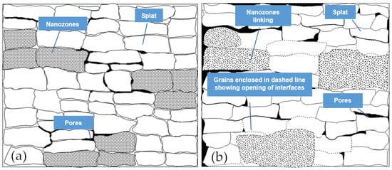
Figure 7.
Schematic representation of the major microstructural features in Ntbc after two stages of sintering; (a) first stage up to 20 h approximately and (b) second stage beyond 20 h.
The change of crack path was attributed to the reduced stress concentration of the crack tip and compressive stress inside the unmelted nano-particles (UNPs). Therefore, the UNPs played a significant role in prolonging the lifetime of the nanostructured TBCs during thermal cycling. The reason was that these UNPs seriously affected the value and distribution of residual stress. The increase of UNPs effectively decreased the elastic modulus and residual stress of TC. However, once the UNPs was less than a certain range, the mechanical properties of TC decreased significantly and further shortened the lifetime of the TBCs during thermal cycling. Combined with the simulation and previous experimental results above, it was found that, when the UNPs were in a range of 20%–30%, the TBCs had superior thermal shock resistance [22].
8. Residual Stress
Residual stresses develop in TBCs due to a number of factors and are the most significant cause for premature failure, as discussed separately. The ultimate consequence of the evolution of residual stress results in early crack initiation and its subsequent growth, leading to final failure by top coat spallation. Several studies have demonstrated that the residual stress level in TBCs largely depends on the local microstructure and interface geometry. Differences in local microstructures, including porosity and microcrack size and distribution, build up during splat deposition, and this difference yields variations in residual stress, both in nature and magnitude [124]. It is worth noting that the first traces of stress build up in TBC during the coating deposition process. The rate of cooling during solidification after splat deposit induces variations in stress during coating processing, and, during these times, both kinds of porosities, namely interlamellar and globular pores, are created, affecting the stress level. Localized variations in geometry could change the hydrostatic stress over −0.25 to −2.0 GPa in oxide scale. The localized concentration of stress at distributed sites triggers crack nucleation under thermomechanical fatigue. Moreover, the local hydrostatic stress magnifies with scaling spallation. Stress building is also affected by TEC mismatch among layers, sintering effects of the ceramic layer, creep of the TGO layer, substrate geometry, etc. [1]. The stress state is also affected by the mechanical and physical properties of the layers. The failure mechanisms arising out of the residual stress distribution (in-built and/or arising out of thermo-cyclic conditions) in TBCs are cracks that lead to spallation and delamination and poor adhesion [125]. In Ntbc, the increase of unmelted nanoparticle content plays a decisive role in reducing the overall thermal stress [22].
Realistic prediction of the tensile residual stress due to TGO growth and the safe working life of TBC are a very important part of TBC design and maintenance. These stresses can lead to the initiation and propagation of cracks within the TBC and eventual spallation or delamination failure at the TGO interface [1]. Several mechanical and physical properties and TGO thickness are dependent on temperature and can significantly affect the stress state in TBCs [126]. A great deal of analytical and computational models have been proposed, and simulation studies have been performed to predict stress distributions in Ctbc systems considering TGO thickness, TEC mismatch, substrate geometry, TGO thickness, etc. However, such studies are limited in the case of Ntbc systems. The increase in the TGO thickness certainly results in the development of larger stresses.
The thermal mismatch stresses near the TGO layer occur during thermal cycling, which is due to the great differences in physical, thermal and mechanical properties of adjacent layers [97]. The damage and failure of TBCs are related to the mismatch of the thermal expansion coefficient. The cracks generated by the residual stress may nucleate and expand to the interface, which will affect the stress state in the TBCs. Residual stress in Ntbc is expected to be lower compared to Ctbc because of a number of factors. The tendency for TGO formation and growth as discussed earlier is lower, and so the TGO structure will be dense and compact [37,127,128,129]. Besides, Ntbc have fewer pinholes and voids that help in keeping the stress level lower. However, prolonged sintering and phase transformation from the tetragonal to the monoclinic phase contribute to increased residual stress with a change from tensile to compressive nature.
9. Sintering Resistance
Performance degradation of TBCs during service is of major concern. TBCs encounter high temperature over their working life and are sintered, causing considerable changes in the structures and properties of the as-sprayed conditions. Significant sintering effects result in microstructural evolution, densification, TGO growth, crack and pore healing, thermo-mechanical degradation, etc. [4,58,130,131,132]. This section aims at analyzing the significant differences in these effects observed in two TBCs. The sintering effects are primarily responsible for the differences in failure mechanisms and working life. In Ntbc, overall sintering effects tend to be counteracted because of the more complex bimodal structure and because of various regions responding differently to sintering. Nanozones in Ntbc respond to sintering at higher rates than the rate observed for the matrix [12,55]. The details of the microstructural analysis is in the earlier section. The bimodal structure consists of molten YSZ and resolidified regions as a matrix and unmelted YSZ particles and porosity as nanozones. A high driving force tends to result in faster sintering effects in nanozones. Faster shrinking induces coarse porosity within the coating structure. Other sintering effects in Ntbc include a grain size increase in the direction of the columnar structure [54,58,75]. The activation energy for this nanograin growth is reported to be 6.5 kJ/mol, as compared to a high value of 580 kJ/mol for bulk YSZ. The pores associated with the nanograins facilitate the grain growth at a lower activation energy when exposed to high temperature around 1100 °C. The failure of Ntbc due to the formation of coarse crack during sintering was also suggested by Lima et al. earlier [54]. Different sintering rates in different phases in Ntbc proved to be beneficial for higher sintering resistance and longer microstructural stability. A larger fraction of nanogranules in the deposited coating, with size less than 100 nm in Ntbc, was recommended for improved Ntbc microstructure [12,13]. The rates and extent of sintering effects in Ctbc are lower as compared to those observed for Ntbc when both TBCs were exposed to a high temperature of 1400 °C. The thermal diffusivity and El of Ntbc was reported to be significantly lower than for Ctbc due to sintering at 1400 °C for 20 h.
The sintering kinetics and effects over time has two distinct stages in Ntbc. In the accelerated sintering stage, the nanostructure of the TBC with nanograins persists up to a short duration (around 10 to 20 h), and this is followed by a long second stage when the nanostructure is mostly lost with continued sintering [70]. The first stage is characterized by a rapid increase in two important behaviors, i.e., in nano hardness and in El because of rapid densification. Changes in these two properties occur slightly. Most of the changes during the second sintering stage involve densification, grain growth and healing at slow to moderate rates. The bimodal distribution of the hardness and modulus data as found in the first stage will be lost in the second stage due to the loss of nanostructuring. The nanozones in Ntbc slow down the sintering effects and thus the degradation of properties and performance. A sharper increase in thermal conductivity during the first stage of sintering in Ntbc is also observed [55,68]. In APS-processed Ctbc, pores are present between successive layers of deposit (known as intersplat) and numerous microcracks are also present within each layer (known as intrasplat) [1]. Prolonged sintering healing of defects occurs. This degrades the quality of Ctbc because, as the El. increases, strain tolerance of top coat decreases, enhancing the tendency for spallation. Zhu and Miller reported the increase in El can be as high as 25% after 11 h of sintering at 949 °C [68].
A systematic investigation with lower YSZ content (3 and 5%YSZ) Ntbc revealed a significant increase in the porosity level after sintering at 1400 °C around nanostructured zones. Both densification and grain growth was also reported as mentioned in earlier paragraphs, though the 3%YSZ coating offered better sintering resistance than the other coating [15,88]. The sintering effects in Ntbc with stainless steel substrate and YSZ topcoat was studied earlier for different thermal exposures at 1200 °C. The nano grain size increased from 63 nm for the as-sprayed state to 208 nm for sintering at 200 h. However, there was no change in the tetragonal phase zirconia during annealing [68] over the sintering time. The size and density of pores declined drastically, and microcracks healed rapidly within the first 10 h of Ntbc processed by the APS method using electro-sprayed 8%YSZ nanostructured particles as feedstock powder. The porous bimodal structure made by nanosized YSZ particles exhibited higher sintering resistance, thermal insulation and phase stability compared to those from Ctbc. The coating measured the thermal conductivity of 0.70 W/mk, which is relatively lower, but this increased gradually to 1.29 W/mk with continued sintering at 1400 °C for 128 h [7].
Phase stability becomes an issue because of sintering at temperature over 1200 °C. Long sintering has another effect when martensitic phase (m-ZrO2) transformation occurs from the tetragonal to monoclinic phase. Around 5% to 7% volume change is accompanied by this transformation when residual stress builds up, causing cracking and the spallation of the top coat. In addition, this phase change is responsible for an increase in thermal conductivity, and a phase monoclinic has inherent higher conductivity [7,13,75,133]. Voids forming around the nanostructured zone reduce the accumulated stress. However, intersplat cracking during the decomposition process remains absent.
10. Crack Propagation and Failure
Reliability, stability and integrity are closely associated with the long-term performance of the thermal barrier coating system. The damage and ultimate failures of Ntbc are related to the crack nucleation and propagation, which originates from residual stress build-up from a large number of sources [17]. Again, the global and local microstructure and the properties control the crack initiation and propagation behavior. An in-depth understanding of the interrelation between the microstructure and the crack growth behavior of TBC is very important for the modeling for lifespan prediction. In Ntbc structure, cracks are distributed in the tensile stress zone of unmelted nano-particle (UNPs) regions with a complex microcrack network at their periphery [17]. A finite-element-based modeling of the UNP region in Ntbc structure attempts to relate the stress and crack propagation directions in and around UNP regions. The accumulation of nano-particles creates a complex tensile or shear stress environment around the initial stage. In the final stage, both the tensile stress and shear stress coexisted inside the UNPs [134,135,136]. The shear stress component tends to become more dominant on the longitudinal crack propagation behavior.
Figure 8 schematically represents the generic damage progression and failure process as envisaged for the tTBC system [56]. In as-sprayed TBCs, thin uniform TGO at the TC/BC interface is present and is followed by a network of fine microcracks in close TGO vicinity and within the crest of the TC and BC undulations. Microcracks gradually link up and grow in size with thermal cycling to separate at TGO/TC and BC/TGO and through TGO.
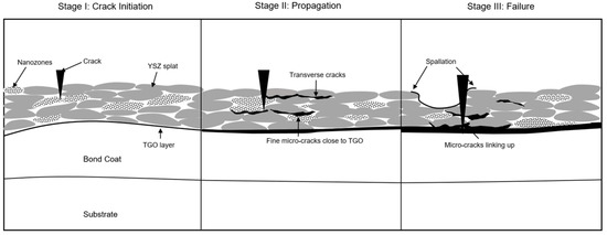
Figure 8.
Schematic illustration of the three stages of damage progression in TC microstructures leading to the failure of Ntbc.
In contrast, in plasma-sprayed YSZ layers in Ctbc, cracks [5,85,137]:
- (i)
- develop on top of the roughness crests (at the TGO/YSZ or TGO/ bond coat interface or within the TGO) and then propagate into the YSZ top coat, usually at off-peak locations where maximum tensile normal stresses are found [88]
- (ii)
- propagate in the top coat through the opening of pre-existing microcracks above the interface. Crack growth is particularly accelerated once the TGO grows beyond a critical thickness threshold [13].
Cracking damages developed during TCF in Ntbc and Ctbc are schematically represented in Figure 8. Most frequently, cracks tend to propagate through the TGO as well as the top coat, and to a certain extent cracks propagate near the interface. Crack size vary widely from a few microns at nucleation to a few mm at failure [98].
11. Performance and Lifetime Modeling
A balanced bimodal structure in Ntbc contributes to the superior reliability in performance and excellent lifetime with respect to conventional TBCs. It has been widely reported that nanostructured TBCs are potentially promising to achieve higher thermal cycling lifetime [55]. However, in spite of considerable outstanding behavior exhibited, little attention has so far been paid in research towards the development of performance and lifetime prediction modeling for nanostructured TBCs. In an earlier section, a number of key parameters are listed for the degradation and failure in Ntbc, and an in-depth understanding of the interaction and interplay among them is most essential [35]. A few lifespan and behavior prediction modeling approach for thermal cycle fatigue proposed for the conventional type of TBC are briefly mentioned here:
- (i)
- A model based on a modified Paris’ law using a so called “effective crack length” during thermal cycling. The life model makes use of a Paris’ law type equation to estimate the cycles to failure based on microcrack growth. The fitting parameters for Paris’ law were obtained from the experimentally measured crack lengths after the interruption of TCF tests at different cycles [104,138,139,140,141].
- (ii)
- Wei et al. considered oxidation, creep and sintering in their finite-element-based life time model for predicting the life of conventional TBCs [142].
- (iii)
- A lifetime prediction model based on residual stress and considering the characteristics of bond coat/TGO/top coat interfaces was proposed by Zhang et al. [143].
- (iv)
- Vassen et al. proposed a life-prediction model integrating the crack growth with the energy-release rate criterion [110].
- (v)
- A damage mechanics-based model under thermal loading conditions of a TBC was proposed by Busso et al. The failure is assumed to occur by a cleavage-type mechanism within the YSZ [144].
12. Conclusions
The following salient points emerge out of the review. In comparison to the sea of research on Ctbc, the limited work for Ntbc system reports conflicting and incomplete results, demanding more in-depth systematic research.
- Nanostructured coatings being denser and packed with fewer pinholes, and voids allow limited oxygen diffusion. Bimodal (microcolumnar grain from well melted/resolidified splat + nanozones) high content of nanozones reduces the oxygen diffusion reducing the tendency for thermally grown oxide scale. The residual stress in Ntbc is expected to be lower compared to Ctbc because of thinner oxide and denser structure. Few schematics are made to illustrate differences in microstructural features.
- A network of microcracks are distributed in the tensile stress zone of unmelted nanoparticle (UNP) regions at their periphery. The stress environment consisting of tensile and shear stress controls the accumulation and direction of crack propagation initially. However, finally, the shear component tends to become more dominant on the longitudinal crack propagation. Crack propagation in bimodal structure is prevented by splat boundaries and unmelted particles, thereby improving the bonding strength. Significant features in damage progression and failures in both TBCs are captured and represented schematically.
- Thermal cyclic life improvement in nano structured FG TBC by 1.6 times is reported as compared to Ctbc. This increase in TCF life results from a combination of nanostructured feedstock and multiple graded layers. Significant differences in the oxidation mechanisms in FG Ntbc contributes to improved TCF life. Spinels and mixed oxide at a higher temperature reduces the number of cycles even for compositionally graded Ntbc. FG TBCs can decrease thermal expansion mismatch, and the presence of a thinner TGO layer at the alloy/ceramic interface reduces the residual stresses in TBCs, resulting in higher durability.
- Different trends, wide scattering and several inconsistencies in elastic modulus in nano-coatings are observed. Early sintering (10 to 20 h yields a steep hike in modulus, and long sintering reduces the modulus. Nanostructuring effects is maintained in the first stage of sintering, and the densification of the structures dominates the final stage of sintering. In general, the Ntbc exhibit higher EM than Ctbc. The bimodal structure/nanozones in nano-TBC are responsible for superior thermal insulation capability. Other factors, such as lower thermal diffusivity and lower thermal conductivity in Ntbc, support this trend. Defect characteristics, especially the porosity, play a significant role for improved insulation in Ntbc.
Author Contributions
Conceptualization, A.K. and J.M.; methodology, A.K.; software, A.K., J.M. and Y.L.; validation, A.K., J.M. and K.C.; formal analysis, A.K. and K.C.; investigation, A.K. and K.C.; resources, A.K., K.C. and P.C.P.; data curation, J.M., Y.L. and K.C.; writing—original draft preparation, A.K. and J.M.; writing—review and editing, A.K., J.M., Y.L., K.C. and P.C.P.; visualization, A.K. and P.C.P.; supervision, K.C. and P.C.P.; project administration, A.K., Y.L. and K.C. All authors have read and agreed to the published version of the manuscript.
Funding
This research received no external funding.
Institutional Review Board Statement
Not applicable.
Informed Consent Statement
Not applicable.
Data Availability Statement
Not applicable.
Conflicts of Interest
The authors declare no conflict of interest.
References
- Kyaw, S.; Jones, A.; Hyde, T. Predicting failure within TBC system: Finite element simulation of stress within TBC system as affected by sintering of APS TBC, geometry of substrate and creep of TGO. Eng. Fail. Anal. 2013, 27, 150–164. [Google Scholar] [CrossRef]
- Zhang, C.; Chen Avic, C. Failure mechanism of thermal barrier coatings by electron beam physical vapor deposition (EB–PVD) under thermomechanical coupled loads. In Thermal Barrier Coatings; Xu, H., Guo, H., Eds.; Woodhead Publishing Series in Metals and Surface Engineering: Cambridge, UK, 2011; pp. 215–242. [Google Scholar]
- Pourbafrani, M.; Shoja Razavi, S.; Bakhshi, S.R.; Loghman-Estarki, M.R.; Jamali, H. Effect of microstructure and phase of nanostructured YSZ thermal barrier coatings on its thermal shock behaviour. Surf. Eng. 2015, 31, 64–73. [Google Scholar] [CrossRef]
- Lv, B.; Fan, X.; Li, D.; Wang, T.J. Towards enhanced sintering resistance: Air-plasma-sprayed thermal barrier coating system with porosity gradient. J. Eur. Ceram. Soc. 2018, 38, 1946–1956. [Google Scholar] [CrossRef]
- Bolelli, G.; Righi, M.G.; Mughal, M.Z.; Moscatelli, R.; Ligabue, O.; Antolotti, N.; Sebastiani, M.; Lusvarghi, L.; Bemporad, E. Damage progression in thermal barrier coating systems during thermal cycling: A nano-mechanical assessment. Mater. Des. 2019, 166. [Google Scholar] [CrossRef]
- Darolia, R. Thermal barrier coatings technology: Critical review, progress update, remaining challenges and prospects. Int. Mater. Rev. 2013, 58, 315–348. [Google Scholar] [CrossRef]
- Xing, C.; Yi, M.; Shan, X.; Wang, X.; Zhao, X.; Guo, F. Sintering behavior of a nanostructured thermal barrier coating deposited using electro-sprayed particles. J. Am. Ceram. Soc. 2020, 103, 7267–7282. [Google Scholar] [CrossRef]
- Clarke, D.R.; Phillpot, S.R. Thermal barrier coating materials. Mater. Today 2005, 8, 22–29. [Google Scholar] [CrossRef]
- Cao, X.; Vassen, R.; Stoever, D. Ceramic materials for thermal barrier coatings. J. Eur. Ceram. Soc. 2004, 24, 1–10. [Google Scholar] [CrossRef]
- Bakan, E.; Vaßen, R. Ceramic top coats of plasma-sprayed thermal barrier coatings: Materials, processes, and properties. J. Spray Technol. 2017, 26, 992–1010. [Google Scholar] [CrossRef]
- Mercer, C.; Williams, J.R.; Clarke, D.R.; Evans, A.G. On a ferroelastic mechanism governing the toughness of metastable tetragonal-prime (t′) yttria-stabilized zirconia. Proc. R. Soc. A 2007, 463, 1393–1408. [Google Scholar] [CrossRef]
- Lima, R.S.; Marple, B.R. Nanostructured YSZ thermal barrier coatings engineered to counteract sintering effects. Mater. Sci. Eng. A 2008, 485, 182–193. [Google Scholar] [CrossRef] [Green Version]
- Zhao, Y.; Gao, Y. Structural evolution of plasma-sprayed nanoscale 3 mol% and 5 mol% yttria-stabilized zirconia coatings during sintering. Appl. Surf. Sci. 2017, 425, 1033–1039. [Google Scholar] [CrossRef]
- Zhu, D.; Miller, R.A. Development of advanced low conductivity thermal barrier coating. Int. Appl. Ceram. Technol. 2004, 1, 86–94. [Google Scholar] [CrossRef] [Green Version]
- Keshavarz, M.; Hasbullah, I.; Othaman, Z. Thermally oxidised zirconium nanocrystalline thermal barrier coating deposited by EBPVD. J. Mek. 2013, 36, 10–16. [Google Scholar]
- Afrasiabi, A.; Saremi, M.; Kobayashi, A. A comparative study on hot corrosion resistance of three types of thermal barrier coatings: YSZ, YSZ + Al2O3 and YSZ/Al2O3. Mater. Sci. Eng. A 2008, 478, 264–269. [Google Scholar] [CrossRef]
- Paraschiv, A.; Banu, A.; Doicin, C.; Ionica, I. Isothermal oxidation behavior of plasma sprayed conventional and nanostructured thermal barrier coatings. U.P.B. Sci. Bull. 2010, 72, 164–172. [Google Scholar]
- Dong, H.; Yang, G.J.; Li, C.-X.; Luo, X.-T.; Li, C.-J. Effect of TGO thickness on thermal cyclic lifetime and failure mode of plasma-sprayed TBCs. J. Am. Ceram. Soc. 2014, 97, 1226–1232. [Google Scholar] [CrossRef]
- Keyvani, A.; Saremi, M.; Sohi, M.H.; Valefi, Z. A comparison on thermomechanical properties of plasma-sprayed conventional and nanostructured YSZ TBC coatings in thermal cycling. J. Alloys Compd. 2012, 541, 488–494. [Google Scholar] [CrossRef]
- Keyvani, A.; Saremi, M.; Sohi, M.H. Oxidation resistance of the nanostructured YSZ coating on the IN-738 superalloy. J. Ultrafine Grained Nanostruct. Mater. 2014, 47, 89–96. [Google Scholar]
- Jamali, H.; Mozafarinia, R.; Shoja, R.; Razavi, R.S.; Ahamadi-Pidani, R.; Reza Loghman-Estarki, M.R. Fabrication and evaluation of plasma-sprayed nanostructured and conventional YSZ thermal barrier coatings. Curr. Nanosci. 2012, 8, 402–409. [Google Scholar] [CrossRef]
- Zhang, L.; Wang, Y.; Fan, W.; Gao, Y.; Sun, Y.; Bai, Y. A simulation study on the crack propagation behavior of nanostructured thermal barrier coatings with tailored microstructure. Coatings 2020, 10, 722. [Google Scholar] [CrossRef]
- Haoran, L.; Chang-An, W.; Chenguang, Z. Thermo-physical properties of rare-earth hexaaluminates LnMgAl11O19 (Ln: La, Pr, Nd, Sm, Eu and Gd) magnetoplumbite for advanced thermal barrier coatings. J. Eur. Ceram. Soc. 2015, 35, 1297–1306. [Google Scholar] [CrossRef]
- Bespalko, Y.; Kuznetsova, T.; Kriger, T.; Chesalov, Y.; Lapina, O.; Ishchenko, A.; Larina, T.; Sadykov, V.; Stathopoulos, V. La2Zr2O7/LaAlO3 composite prepared by mixing precipitated precursors: Evolution of its structure under sintering. Mater. Chem. Phys. 2020, 251, 1297–1306. [Google Scholar] [CrossRef]
- Zhang, S.; Lei, M.; Wan, M.; Huang, C. Morphology, hardness and wear properties of plasma cladding NiCrCu coating on M2 high-speed steel. Coatings 2020, 10, 641. [Google Scholar] [CrossRef]
- Pandey, A.; Patel, A.K.; Ariharan, S.; Kumar, V.; Sharma, R.K.; Kanhed, S. Enhanced tribological and bacterial resistance of carbon nanotube with ceria- and silver-incorporated hydroxyapatite biocoating. Nanomaterials 2018, 8, 363. [Google Scholar] [CrossRef] [PubMed] [Green Version]
- Jiang, C.; Jordan, E.H.; Harris, A.B.; Gell, M.; Roth, J. Double-layer gadolinium zirconate/yttria-stabilized zirconia thermal barrier coatings deposited by the solution precursor plasma spray process. J. Therm. Spray Technol. 2015, 6, 895–906. [Google Scholar] [CrossRef]
- Gok, M.G.; Goller, G. State of the art of gadolinium zirconate based thermal barrier coatings: Design, processing and characterization. In Methods for Film Synthesis and Coating Procedures; IntechOpen: London, UK, 2019. [Google Scholar]
- Zhang, J.; Xingye, G.; Yeon, J. Lanthanum zirconate based thermal barrier coatings: A review. Surf. Coat. Technol. 2017, 323, 18–29. [Google Scholar] [CrossRef] [Green Version]
- Sniezewski, J.; Vidal, V.; Lours, P.; Le Maoult, Y. Thermal barrier coatings adherence and spallation: Interfacial indentation resistance and cyclic oxidation behaviour under thermal gradient. Surf. Coat. Technol. 2009, 204, 807–811. [Google Scholar] [CrossRef] [Green Version]
- Zhang, X.C.; Xu, B.S.; Wang, H.D.; Jiang, Y.; Wu, Y.X. Application of functionally graded interlayer on reducing the residual stress discontinuities at interfaces within a plasma-sprayed thermal barrier coating. Surf. Coat. Technol. 2007, 201, 5716–5719. [Google Scholar] [CrossRef]
- Kumar, A.; Patnaik, P.C.; Chen, K. Damage assessment and fracture resistance of functionally graded advanced thermal barrier coating systems: Experimental and analytical modeling approach. Coatings 2020, 10, 474. [Google Scholar] [CrossRef]
- Izadinia, M.; Soltani, R.; Sohi, M.H. Effect of segmented cracks on TGO growth and life of thick thermal barrier coating under isothermal oxidation conditions. Ceram. Int. 2020, 46, 7475–7481. [Google Scholar] [CrossRef]
- Fan, W.; Bai, Y. Review of suspension and solution precursor plasma sprayed thermal barrier coatings. Ceram. Int. 2016, 42, 14299–14312. [Google Scholar] [CrossRef]
- Sun, J.; Zhang, L.; Zhao, D. Microstructure and thermal cycling behavior of nanostructured yttria partially stabilized zirconia (YSZ) thermal barrier coatings. J. Rare Earths 2010, 28, 198–201. [Google Scholar] [CrossRef]
- Lamuta, C.; Di Girolamo, G.; Pagnotta, L. Microstructural, mechanical and tribological properties of nanostructured YSZ coatings produced with different APS process parameters. Ceram. Int. 2015, 41, 8904–8914. [Google Scholar] [CrossRef]
- Ghosh, S. Thermal barrier ceramic coatings—A review. In Advanced Ceramic Processing; IntechOpen: London, UK, 2015. [Google Scholar]
- Martena, M.; Botto, D.; Fino, P.; Sabbadini, S.; Gola, M.M.; Badini, C. Modelling of TBC system failure: Stress distribution as a function of TGO thickness and thermal expansion mismatch. Eng. Fail. Anal. 2006, 13, 409–426. [Google Scholar] [CrossRef]
- Clarke, D.R.; Oechsner, M.; Padture, N.P. Thermal-barrier coatings for more efficient gas-turbine engines. MRS Bull. 2012, 37, 891–898. [Google Scholar] [CrossRef] [Green Version]
- Mehbooba, G.; Liua, M.-J.; Xua, T.; Hussaina, S.; Mehboobb, G.; Tahira, A. A review on failure mechanism of thermal barrier coatings and strategies to extend their lifetime. Ceram. Int. 2020, 20, 8497–8521. [Google Scholar] [CrossRef]
- Busso, E.P.; Wright, L.; Evans, H.E.; McCartney, L.N.; Saunders, S.R.J.; Osgerby, S.; Nunn, J. A physics-based life prediction methodology for thermal barrier coating systems. Acta Mater. 2007, 55, 1491–1503. [Google Scholar] [CrossRef] [Green Version]
- Strangman, T.; Raybould, D.; Jameel, A.; Baker, W. Damage mechanisms, life prediction, and development of EB-PVD thermal barrier coatings for turbine airfoils. Surf. Coat. Technol. 2007, 202, 658–664. [Google Scholar] [CrossRef]
- Bardelle, A.; Moreau, C.; Themelis, N.J.; Chazelas, C. A perspective on plasma spray technology. Plasma Chem. Plasma Process. 2015, 35, 491–509. [Google Scholar] [CrossRef]
- Zhou, D.; Guillon, O.; Vaßen, R. Development of YSZ thermal barrier coatings using axial suspension plasma spraying. Coatings 2017, 7, 120. [Google Scholar] [CrossRef] [Green Version]
- Li, G.R.; Wang, L.S.; Yang, G.J. A novel composite-layered coating enabling self-enhancing thermal barrier performance. Scr. Mater. 2019, 163, 142–147. [Google Scholar] [CrossRef]
- Zhang, W.W.; Li, G.R.; Zhang, Q.; Yang, G.J.; Zhang, G.W.; Mu, H.M. Bimodal TBCs with low thermal conductivity deposited by a powder-suspension co-spray process. J. Mater. Sci. Technol. 2018, 34, 1293–1304. [Google Scholar] [CrossRef]
- Li, G.R.; Yang, G.J.; Chen, X.F.; Li, C.X.; Li, C.J. Strain/sintering co-induced multiscale structural changes in plasma-sprayed thermal barrier coatings. Ceram. Int. 2018, 44, 14408–14416. [Google Scholar] [CrossRef]
- Chen, Q.Y.; Peng, X.Z.; Yang, G.J.; Li, C.X.; Li, C.J. Characterization of plasma jet in plasma spray-physical vapor deposition of YSZ using a <80 kW shrouded torch based on optical emission spectroscopy. J. Therm. Spray Technol. 2015, 24, 1038–1045. [Google Scholar]
- Wang, L.; Liu, C.G.; Zhong, H.; Zhao, Y.X.; Zhao, H.Y.; Yang, J.S.; Tao, S.Y.; Wang, Y. Investigation of crack propagation behavior of atmospheric plasma-sprayed thermal barrier coatings under uniaxial tension using the acoustic emission technique. J. Therm. Spray Technol. 2015, 24, 296–308. [Google Scholar] [CrossRef]
- Evans, A.G.; Mumm, D.R.; Hutchinson, J.W.; Meier, G.H.; Pettit, F.S. Mechanisms controlling the durability of thermal barrier coatings. Prog. Mater. Sci. 2011, 46, 505–553. [Google Scholar] [CrossRef]
- Schulz, U.; Schmücker, M. Microstructure of ZrO2 thermal barrier coatings applied by EB-PVD. Mater. Sci. Eng. A 2000, 276, 1–8. [Google Scholar] [CrossRef]
- Hashemi, S.M.; Parvin, N.; Valefi, Z. Effect of addition of multimodal YSZ and SiC powders on the mechanical properties of nanostructured Cr2O3 plasma-sprayed coatings. J. Therm. Spray Technol. 2019, 28, 544–562. [Google Scholar] [CrossRef]
- Ghosh, D.; Shukhla, A.K.; Roy, H. Nano structured plasma spray coating for wear and high temperature corrosion resistance applications. J. Inst. Eng. 2014, 95, 57–64. [Google Scholar] [CrossRef]
- Wang, Y.; Bai, Y.; Liu, K.; Wang, J.W.; Kang, Y.X.; Li, J.R.; Chen, H.Y.; Li, B.Q. Microstructural evolution of plasma sprayed submicron-/nano-zirconia-based thermal barrier coatings. Appl. Surf. Sci. 2016, 363, 101–112. [Google Scholar] [CrossRef]
- Li, G.-R.; Yang, G.-J.; Li, C.-X.; Li, C.-J. A comprehensive mechanism for the sintering of plasma-sprayed nanostructured thermal barrier coatings. Ceram. Int. 2017, 43, 9600–9615. [Google Scholar] [CrossRef]
- Zhang, Q.; Li, C.-J.; Li, Y.; Zhang, S.-L.; Wang, X.-R.; Yang, G.-J.; Li, C.-X. Thermal failure of nanostructured thermal barrier coatings with cold-sprayed nanostructured NiCrAlY bond coat. J. Therm. Spray Technol. 2008, 17, 838–845. [Google Scholar] [CrossRef]
- Chen, H.; Ding, C.X. Nanostructured zirconia coating prepared by atmospheric plasma spraying. Surf. Coat. Technol. 2002, 150, 31–36. [Google Scholar] [CrossRef]
- Wang, N.; Zhou, C.N.; Gong, S.K.; Xu, H.B. Heat treatment of nanostructured thermal barrier coating. Ceram. Int. 2007, 33, 1075–1081. [Google Scholar] [CrossRef]
- Lima, R.S.; Marple, B.R. Thermal spray coatings engineered from nanostructured ceramic agglomerated powders for structural, thermal barrier and biomedical applications: A review. J. Therm. Spray. Technol. 2007, 16, 40–63. [Google Scholar] [CrossRef] [Green Version]
- Zhou, C.G.; Wang, N.; Wang, Z.B.; Gong, S.K.; Xu, H.B. Thermal cycling life and thermal diffusivity of a plasma-sprayed nanostructured thermal barrier coating. Scr. Mater. 2004, 51, 945–948. [Google Scholar] [CrossRef]
- Zhou, C.G.; Wang, N.; Xu, H.B. Comparison of thermal cycling behavior plasma-sprayed nanostructured and traditional thermal barrier coatings. Mater. Sci. Eng. A. 2007, 452–453, 569–574. [Google Scholar] [CrossRef]
- Lima, R.S.; Kucuk, A.; Berndt, C.C. Integrity of nanostructured partially stabilized zirconia after plasma spray processing. Mater. Sci. Eng. A 2001, 313, 75–82. [Google Scholar] [CrossRef]
- Zhou, C.; Zhang, Q.; Li, Y. Thermal shock behavior of nanostructured and microstructured thermal barrier coatings on a Fe-based alloy. Surf. Coat. Technol. 2013, 217, 70–75. [Google Scholar] [CrossRef]
- Zhao, Y.; Gao, Y. Deposition of nanostructured YSZ coating from spray-dried particles with no heat treatment. Appl. Surf. Sci. 2015, 346, 406–414. [Google Scholar] [CrossRef]
- Saremi, M.; Keyvani, A.; Sohi, M.H. Hot corrosion resistance and mechanical behavior of atmospheric plasma sprayed conventional and nanostructured zirconia coatings. Int. J. Mod. Phys. 2012, 5, 720–727. [Google Scholar] [CrossRef]
- Bai, Y.; Han, Z.H.; Li, H.Q.; Xu, C.; Xu, Y.L.; Wang, Z.; Ding, C.H.; Yang, J.F. High performance nanostructured ZrO2 based thermal barrier coatings deposited by high efficiency supersonic plasma spraying. Appl. Surf. Sci. 2011, 257, 7210–7216. [Google Scholar] [CrossRef]
- Daroonparvar, M.; Yajid, M.A.M.Y.; Yusof, N.M.; Hussain, M.S. Improved thermally grown oxide scale in air plasma sprayed NiCrAlY/nano-YSZ coatings. J. Nanomater. 2013, 2013, 520104. [Google Scholar] [CrossRef] [Green Version]
- Wu, Z.; Ni, L.; Yu, Q.; Zhou, C. Effect of thermal exposure on mechanical properties of a plasma-sprayed nanostructured thermal barrier coating. J. Therm. Spray Technol. 2012, 21, 169–175. [Google Scholar] [CrossRef]
- Sezavar, A.; Sajjadi, S.A.; Babakhani, A.; Peng, R.L.; Yuan, K. Oxidation behavior of a nanostructured compositionally graded layer (CGL) thermal barrier coating (TBC) deposited on IN-738LC. Surf. Coat. Technol. 2019, 374, 374–382. [Google Scholar] [CrossRef]
- Ghasemi, R.; Vakilifard, H. Plasma-sprayed nanostructured YSZ thermal barrier coatings: Thermal insulation capability and adhesion strength. Ceram. Int. 2017, 43, 8556–8563. [Google Scholar] [CrossRef]
- Jiang, K.; Liu, S.; Wang, X. Phase stability and thermal conductivity of nanostructured tetragonal yttria–stabilized zirconia thermal barrier coatings deposited by air–plasma spraying. Ceram. Int. 2017, 43, 12633–12640. [Google Scholar] [CrossRef]
- Fauchais, P.; Montavon, G.; Lima, R.S.; Marple, B.R. Engineering a new class of thermal spray nano-based microstructures from agglomerated nanostructured particles, suspensions and solutions: An invited review. J. Phy. D Appl. Phys. 2011, 44, 093001. [Google Scholar] [CrossRef] [Green Version]
- Gong, W.B.; Sha, C.K.; Sun, D.Q.; Wang, W.Q. Microstructures and thermal insulation capability of plasma-sprayed nanostructured ceria stabilized zirconia coatings. Surf. Coat. Technol. 2006, 201, 3109–3115. [Google Scholar] [CrossRef]
- Lima, R.S.; Marple, B.R. Toward highly sintering-resistant nanostructured ZrO2-7wt.%Y2O3 coatings for TBC applications by employing differential sintering. J. Therm. Spray. Technol. 2008, 17, 846–852. [Google Scholar] [CrossRef] [Green Version]
- Wu, J.; Guo, H.; Zhou, L.; Wang, L.; Gong, S. Microstructure and thermal properties of plasma sprayed thermal barrier coatings from nanostructured YSZ. J. Therm. Spray Technol. 2010, 19, 1186–1194. [Google Scholar] [CrossRef]
- Yu, Q.; Rauf, A.; Wang, N.; Zhou, C. Thermal properties of plasma-sprayed thermal barrier coating with bimodal structure. Ceram. Int. 2011, 37, 1093–1099. [Google Scholar] [CrossRef]
- Liu, C.; Zhang, Z.; Jiang, X.; Liu, M.; Zhu, Z. Comparison of thermal shock behaviors between plasma-sprayed nanostructured and conventional zirconia thermal barrier coatings. Trans. Nonferrous Met. Soc. China 2009, 19, 99–107. [Google Scholar] [CrossRef]
- Bengtsson, P.; Johannesson, T. Characterization of microstructural defects in plasma-sprayed thermal barrier coatings. J. Therm. Spray Technol. 1995, 4, 245–251. [Google Scholar] [CrossRef]
- Fargas, G.; Casellas, D.; Llanes, L.; Anglada, M. Thermal shock resistance of yttria-stabilized zirconia with Palmqvist indentation cracks. J. Eur. Ceram. Soc. 2003, 23, 107–114. [Google Scholar] [CrossRef]
- Jamali, H.; Mozafarinia, R.; Shoja, R.R.; Ahmadi-Pidani, R. Thermal shock resistance of plasma-sprayed nanostructured and conventional YSZ thermal barrier coatings. Ceram. Int. 2012, 38, 6705–6712. [Google Scholar] [CrossRef]
- Karthikeyan, J.; Berndt, C.C.; Tikkanen, J.; Reddy, S.; Herman, H. Plasma spray synthesis of nanomaterial powders and deposits. Mater. Sci. Eng. A 1997, 238, 275–286. [Google Scholar] [CrossRef]
- Ajdelstajn, L.; Tang, F.; Kim, G.E.; Provenzano, V.; Schoenung, J.M. Synthesis and oxidation behavior of nanocrystalline MCrAlY bond coatings. J. Therm. Spray Technol. 2005, 14, 23–30. [Google Scholar] [CrossRef]
- Sezavar, A.; Sajjadi, S.A.; Babakhani, A.; Peng, R.L. Thermal cyclic fatigue behavior of nanostructured YSZ/NiCrAlY compositionally graded thermal barrier coatings. Oxid. Met. 2019, 92, 89–107. [Google Scholar] [CrossRef]
- Jonnalagadda, K.P.; Eriksson, R.; Yuan, K.; Li, X.-H.; Ji, X.; Yu, Y.; Peng, R.L. A study of damage evolution in high purity nano TBCs during thermal cycling: A fracture mechanics based modelling approach. J. Eur. Ceram. Soc. 2017, 37, 2889–2899. [Google Scholar] [CrossRef]
- Zhou, H.; Li, F.; He, B.; Wang, J.; Sun, B.D. Nanostructured yttria stabilized zirconia coatings deposited by air plasma spraying. Trans. Nonferrous Met. Soc. China 2007, 17, 389–393. [Google Scholar] [CrossRef]
- Di Girolamo, G.; Marra, F.; Blasi, C.; Serra, E.; Valente, T. Microstructure, mechanical properties and thermal shock resistance of plasma sprayed nanostructured zirconia coatings. Ceram. Int. 2011, 37, 2711–2717. [Google Scholar] [CrossRef]
- Lavasani, H.Q.; Valefi, Z.; Ehsani, N.; Masoule, S.T. Comparison of the effect of sintering on the microstructure, micro hardness and phase composition of conventional and nanostructured YSZ TBCs. Ceram. Int. 2017, 43, 12497–12504. [Google Scholar] [CrossRef]
- Zhao, X.-D.; Zeng, K.-L.; Xie, J.-G.; Li, Z.-D. Nanostructured lanthanum zirconate coating and its thermal stability properties. J. Iron Steel Res. Int. 2007, 14, 147–151. [Google Scholar] [CrossRef]
- Gell, M.; Jordan, E.H.; Sohn, Y.H.; Goberman, D.; Shaw, L.; Xiao, T.D. Development and implementation of plasma sprayed nanostructured ceramic coatings. Surf. Coat. Technol. 2001, 146–147, 48–54. [Google Scholar] [CrossRef]
- Lima, R.S.; Marple, B.R. Enhanced ductility in thermally sprayed titania coating synthesized using a nanostructured feedstock. Mater. Sci. Eng. A 2005, 395, 269–280. [Google Scholar] [CrossRef] [Green Version]
- Chen, D.; Luo, F.; Lou, X.; Qing, Y.; Zhou, W.; Zhu, D. Comparison of thermal insulation capability between conventional and nanostructured plasma sprayed YSZ coating on Ni3Al substrates. Ceram. Int. 2017, 43, 4324–4329. [Google Scholar] [CrossRef]
- Zhou, F.; Wang, Y.; Liu, M.; Deng, C.; Zhang, X. Thermo-physical and thermal insulation properties of multi-scale nanostructured thermal barrier coatings using as-prepared t′-8YSZ feedstocks. Ceram. Int. 2019, 45, 24096–24103. [Google Scholar] [CrossRef]
- Chi, W.G.; Sampath, S. Microstructure-thermal conductivity relationships for plasma-sprayed yttria-stabilized zirconia coatings. J. Am. Ceram. Soc. 2008, 91, 2636–2645. [Google Scholar] [CrossRef]
- Li, G.; Xie, H.; Yang, G.; Liu, G.; Li, C.; Li, C. A comprehensive sintering mechanism for TBCs-part I: An overall evolution with two-stage kinetics. J. Am. Ceram. Soc. 2017, 100, 2176–2189. [Google Scholar] [CrossRef]
- Limarga, A.M.; Shian, S.; Baram, M.; Clarke, D.R. Effect of high-temperature aging on the thermal conductivity of nanocrystalline tetragonal yttria-stabilized zirconia. Acta Mater. 2012, 60, 5417–5424. [Google Scholar] [CrossRef] [Green Version]
- Yang, D.M.; Gao, Y.; Liu, H.; Sun, C. Thermal shock resistance of bimodal structured thermal barrier coatings by atmospheric plasma spraying using nanostructured partially stabilized zirconia. Surf. Coat. Technol. 2017, 315, 9–16. [Google Scholar] [CrossRef]
- Hu, Z.-C.; Liu, B.; Wang, L.; Cui, Y.-H.; Wang, Y.-W.; Ma, Y.-D.; Sun, W.-W.; Yang, Y. Research progress of failure mechanism of thermal barrier coatings at high temperature via finite element method. Coatings 2020, 10, 732. [Google Scholar] [CrossRef]
- Zhang, W.; Zhang, J.; Wang, H.; Lou, W.; Liu, X. Influences of Cr and Co on the growth of thermally grown oxide in thermal barrier coating during high-temperature exposure. Coatings 2018, 8, 195. [Google Scholar] [CrossRef] [Green Version]
- Daroonparvar, M.; Hussain, M.S.; Yajid, M.A.M. The role of formation of continues thermally grown oxide layer on the nanostructured NiCrAlY bond coat during thermal exposure in air. Appl. Surf. Sci. 2012, 261, 287–297. [Google Scholar] [CrossRef]
- Liang, B.; Zhang, G.; Liao, H.L.; Coddet, C.; Ding, C.X. Structure and tribological performance of nanostructured ZrO2–3 mol% Y2O3 coatings deposited by air plasma spraying. J. Therm. Spray Technol. 2010, 19, 1163–1170. [Google Scholar] [CrossRef]
- Samal, S. Thermal plasma technology: The prospective future in material processing. J. Clean. Prod. 2017, 142 Pt 4, 3131–3150. [Google Scholar] [CrossRef]
- Li, S.; An, Y.; Chen, J. Plasma sprayed YSZ coatings deposited at different deposition temperatures, part 2: Tribological performance. Surf. Coat. Technol. 2018, 350, 712–721. [Google Scholar] [CrossRef]
- Xu, R.; Fan, X.L.; Zhang, W.X.; Wang, T.J. Interfacial fracture mechanism associated with mixed oxides growth in thermal barrier coating system. Surf. Coat. Technol. 2014, 253, 139–147. [Google Scholar] [CrossRef]
- Chen, W.R.; Wu, X.; Marple, B.R.; Lima, R.S.; Patnaik, P.C. Pre-oxidation and TGO growth behaviour of an air-plasma-sprayed thermal barrier coating. Surf. Coat. Technol. 2008, 202, 3787–3796. [Google Scholar] [CrossRef]
- Ashofteh, A.; Mashhadi, M.M.; Amadeh, A. Thermal shock behavior of multilayer and functionally graded micro- and nano-structured topcoat APS TBCs. Ceram. Int. 2018, 44, 1951–1963. [Google Scholar] [CrossRef]
- Jonnalagaddaa, K.P.; Eriksson, R.; Li, X.-H.; Peng, R.L. Thermal barrier coatings: Life model development and validation. Surf. Coat. Technol. 2019, 362, 293–301. [Google Scholar] [CrossRef]
- Eriksson, R.; Yuan, K.; Li, X.-H.; Peng, R. MCrAlY coating design based on oxidation-diffusion modelling. Part II: Lifing aspects. Surf. Coat. Technol. 2014, 253, 27–37. [Google Scholar] [CrossRef]
- Song, X.; Zhang, J.; Lin, C.; Liu, Z.; Jiang, C.; Kong, M.; Zeng, Y. Microstructures and residual strain/stresses of YSZ coatings prepared by plasma spraying. Mater. Lett. 2019, 240, 217–220. [Google Scholar] [CrossRef]
- Chen, L.; Yang, G.-J.; Li, C.-X.; Li, C.-J. Hierarchical formation of intrasplat cracks in thermal spray ceramic coatings. J. Therm. Spray Technol. 2016, 25, 959–970. [Google Scholar] [CrossRef]
- Vaßen, R.; Giesen, S.; Stöver, D. Lifetime of plasma-sprayed thermal barrier coatings: Comparison of numerical and experimental results. J. Therm. Spray Technol. 2009, 18, 835–845. [Google Scholar] [CrossRef]
- Busso, E.P.; Lin, J.; Sakurai, S. A mechanistic study of oxidation-induced degradation in a plasma-sprayed thermal barrier coating system. Part II: Life prediction model. Acta Mater. 2001, 49, 1529–1536. [Google Scholar] [CrossRef]
- Cheng, B.; Zhang, Y.; Yang, N.; Zhang, M.; Chen, L.; Yang, G.-J.; Li, C.-X.; Li, C.-J. Sintering-induced delamination of thermal barrier coatings by gradient thermal cyclic test. J. Am. Ceram. Soc. 2017, 100, 1820–1830. [Google Scholar] [CrossRef]
- Cheng, B.; Zhang, Y.; Yang, N.; Zhang, M.; Chen, L.; Yang, G.; Li, C.; Li, C. Sintering induced the failure behavior of dense vertically crack and lamellar structured TBCs with equivalent thermal insulation performance. Ceram. Int. 2017, 43, 15459–15465. [Google Scholar] [CrossRef]
- Cheng, B.; Wei, Z.-Y.; Chen, L.; Yang, G.-J.; Li, C.-X.; Li, C.-J. Prolong the durability of La2Zr2O7/YSZ TBCs by decreasing the cracking driving force in ceramic coatings. J. Eur. Ceram. Soc. 2018, 38, 5482–5488. [Google Scholar] [CrossRef]
- Cheng, B.; Yang, G.J.; Zhang, Q.; Yang, N.; Zhang, M.; Zhang, Y.; Li, C.-X.; Li, C. Gradient thermal cyclic behaviour of La2Zr2O7/YSZ DCL-TBCs with equivalent thermal insulation performance. J. Eur. Ceram. Soc. 2018, 38, 1888–1896. [Google Scholar] [CrossRef]
- Gupta, M.; Nylen, P.; Wigren, J. A Modelling approach to designing microstructures in thermal barrier coatings. J. Ceram. Sci. Technol. 2013, 4, 85–91. [Google Scholar]
- Ranjbar-Far, M.; Absi, J.; Mariaux, G.; Shahidi, S. Effect of residual stresses and prediction of possible failure mechanisms on thermal barrier coating system by finite element method. J. Therm. Spray Technol. 2010, 19, 1054–1061. [Google Scholar] [CrossRef]
- Shen, Q.; Yang, L.; Zhou, Y.C.; Wei, Y.G.; Zhu, W. Effects of growth stress in finite-deformation thermally grown oxide on failure mechanism of thermal barrier coatings. Mech. Mater. 2017, 114, 228–242. [Google Scholar] [CrossRef]
- Wang, L.; Wang, Y.; Sun, X.G.; Pan, Z.Y.; He, J.Q.; Li, C.G. Influence of pores on the surface micro-compression mechanical response of thermal barrier coatings fabricated by atmospheric plasma spray-finite element simulation. Appl. Surf. Sci. 2011, 257, 2238–2249. [Google Scholar] [CrossRef]
- Li, Q.; Gou, Y.; Wang, T.-G.; Gu, T.; Yu, Q.; Wang, L. Study on local residual stress in a nanocrystalline Cr2O3 coating by micro-raman spectroscopy. Coatings 2019, 9, 500. [Google Scholar] [CrossRef] [Green Version]
- Tang, F.; Schoenung, J.M. Evolution of Young’s modulus of air plasma sprayed yttria-stabilized zirconia in thermally cycled thermal barrier coatings. Scr. Mater. 2006, 54, 1587–1592. [Google Scholar] [CrossRef]
- Schlichting, K.W.; Padture, N.P.; Jordan, E.H.; Gell, M. Failure modes in plasma-sprayed thermal barrier coatings. Mater. Sci. Eng. A 2003, 342, 120–130. [Google Scholar] [CrossRef]
- Helminiak, M.A.; Yanar, N.M.; Pettit, F.S.; Taylor, T.A.; Meier, G.H. The behavior of high-purity, low-density air plasma sprayed thermal barrier coatings. Surf. Coat.Technol. 2009, 204, 793–796. [Google Scholar] [CrossRef]
- Song, X.; Everaerts, J.; Zhai, W.; Zheng, H.; Tan, A.W.Y.; Sun, W.; Li, F.; Marinescu, I.; Liu, E.; Korsunsky, A.M. Residual stresses in single particle splat of metal cold spray process—Numerical simulation and direct measurement. Mater. Lett. 2018, 230, 152–156. [Google Scholar] [CrossRef]
- Suryanarayana, E.I.C.; Klassen, T.; Ivanov, E. Synthesis of nanocomposites and amorphous alloys by mechanical alloying. J. Mater. Sci. 2011, 46, 6301–6315. [Google Scholar] [CrossRef]
- Ranjbar-Far, M.; Absi, J.; Mariaux, G.; Dubois, F. Simulation of the effect of material properties and interface roughness on the stress distribution in thermal barrier coatings using finite element method. Mater. Des. 2010, 772–781. [Google Scholar] [CrossRef]
- Ni, L.Y.; Liu, C.; Huang, H.; Zhou, C.G. Thermal cycling behavior of thermal barrier coatings with HVOF NiCrAlY bond coat. Therm. Spray Technol. 2011, 20, 1133–1138. [Google Scholar] [CrossRef]
- Rabiei, A.; Evans, A.G. Failure mechanisms associated with the thermally grown oxide in plasma-sprayed thermal barrier coatings. Acta Mater. 2000, 48, 3963–3976. [Google Scholar] [CrossRef]
- Yang, L.; Yang, F.; Long, Y.; Zhao, Y.; Xiong, X.; Zhao, X.; Xiao, P. Evolution of residual stress in air plasma sprayed yttria stabilised zirconia thermal barrier coatings after isothermal treatment. Surf. Coat. Technol. 2014, 251, 98–105. [Google Scholar] [CrossRef]
- Cipitria, A.; Golosnoy, I.O.; Clyne, T.W. Sintering kinetics of plasma-sprayed zirconia TBCs. J. Therm. Spray Technol. 2007, 16, 809–815. [Google Scholar] [CrossRef] [Green Version]
- Vaßen, R.; Czech, N.; Mallener, W.; Stamm, W.; Stöver, D. Influence of impurity content and porosity of plasma-sprayed yttria-stabilized zirconia layers on the sintering behaviour. Surf. Coat. Technol. 2001, 141, 135–140. [Google Scholar] [CrossRef]
- Cernuschi, F.; Lorenzoni, L.; Ahmaniemi, S.; Vuoristo, P.; Mäntylä, T. Studies of the sintering kinetics of thick thermal barrier coatings by thermal diffusivity measurements. J. Eur. Ceram. Soc. 2005, 25, 393–400. [Google Scholar] [CrossRef]
- Bowen, L.; Xie, H.; Xu, R.; Fan, X.L.; Zhang, W.X.; Wang, T.J. Effects of sintering and mixed oxide growth on the interface cracking of air-plasma-sprayed thermal barrier coating system at high temperature. Appl. Surf. Sci. 2016, 360, 461–469. [Google Scholar]
- Gadow, R.; Lischka, M. Lanthanum hexaaluminate—Novel thermal barrier coatings for gas turbine applications—materials and process development. Surf. Coat. Technol. 2002, 151, 392–399. [Google Scholar] [CrossRef]
- Wei, Z.Y.; Cai, H.N.; Li, C.J. Comprehensive dynamic failure mechanism of thermal barrier coatings based on a novel crack propagation and TGO growth coupling model. Ceram. Int. 2018, 44, 22556–22566. [Google Scholar] [CrossRef]
- Jayaprakash, K.; Ponnusami, S.A.; Sergio, T. Modelling the fracture behavior of thermal barrier coatings containing healing particles. Mater. Des. 2018, 157, 75–86. [Google Scholar]
- Kyaw, S.T.; Jones, I.A.; Hyde, T.H. Simulation of failure of air plasma sprayed thermal barrier coating due to interfacial and bulk cracks using surface-based cohesive interaction and extended finite element method. J. Strain Anal. Eng. Des. 2016, 51, 132–143. [Google Scholar] [CrossRef] [Green Version]
- Wang, J.; Sun, J.; Zhang, H.; Dong, S.; Jiang, J.; Deng, L.; Cao, X. Effect of spraying power on microstructure and property of nanostructured YSZ thermal barrier coatings. J. Alloys. Compd. 2018, 730, 471–482. [Google Scholar] [CrossRef]
- Shaw, L.; Goerman, D.; Ren, R.; Gell, M. The dependency of microstructure and properties of nanostructured coatings on plasma spray conditions. J. Surf. Coat. Technol. 2000, 130, 1–8. [Google Scholar] [CrossRef]
- Zhou, F.; Wang, Y.; Wang, L.; Cui, Z.; Zhang, Z. High temperature oxidation and insulation behavior of plasma-sprayed nanostructured thermal barrier coatings. J. Alloys Compd. 2017, 704, 614–623. [Google Scholar] [CrossRef]
- Bargraser, C.; Mohan, P.; Lee, K.; Yang, B.; Suk, J.; Choe, S.; Sohn, Y.H. Life approximation of thermal barrier coatings via quantitative microstructural analysis. Mater. Sci. Eng. A 2012, 549, 76–81. [Google Scholar] [CrossRef]
- Wei, S.; Wang, F.; Fan, Q.; Zhuang, M. Lifetime prediction of plasma-sprayed thermal barrier coating systems. Surf. Coat. Technol. 2013, 217, 39–45. [Google Scholar] [CrossRef]
- Zhang, B.; Chen, K.; Baddour, N.; Patnaik, P.C. Life prediction of atmospheric plasma sprayed thermal barrier coatings using temperature-dependent model parameters. J. Therm. Spray Technol. 2017, 26, 902–912. [Google Scholar] [CrossRef]
- Busso, E.P.; Lin, J.; Sakurai, S.; Nakayama, M. A mechanistic study of oxidation-induced degradation in a plasma-sprayed thermal barrier coating system. Part I: Model formulation. Acta Mater. 2001, 49, 1515–1528. [Google Scholar] [CrossRef]
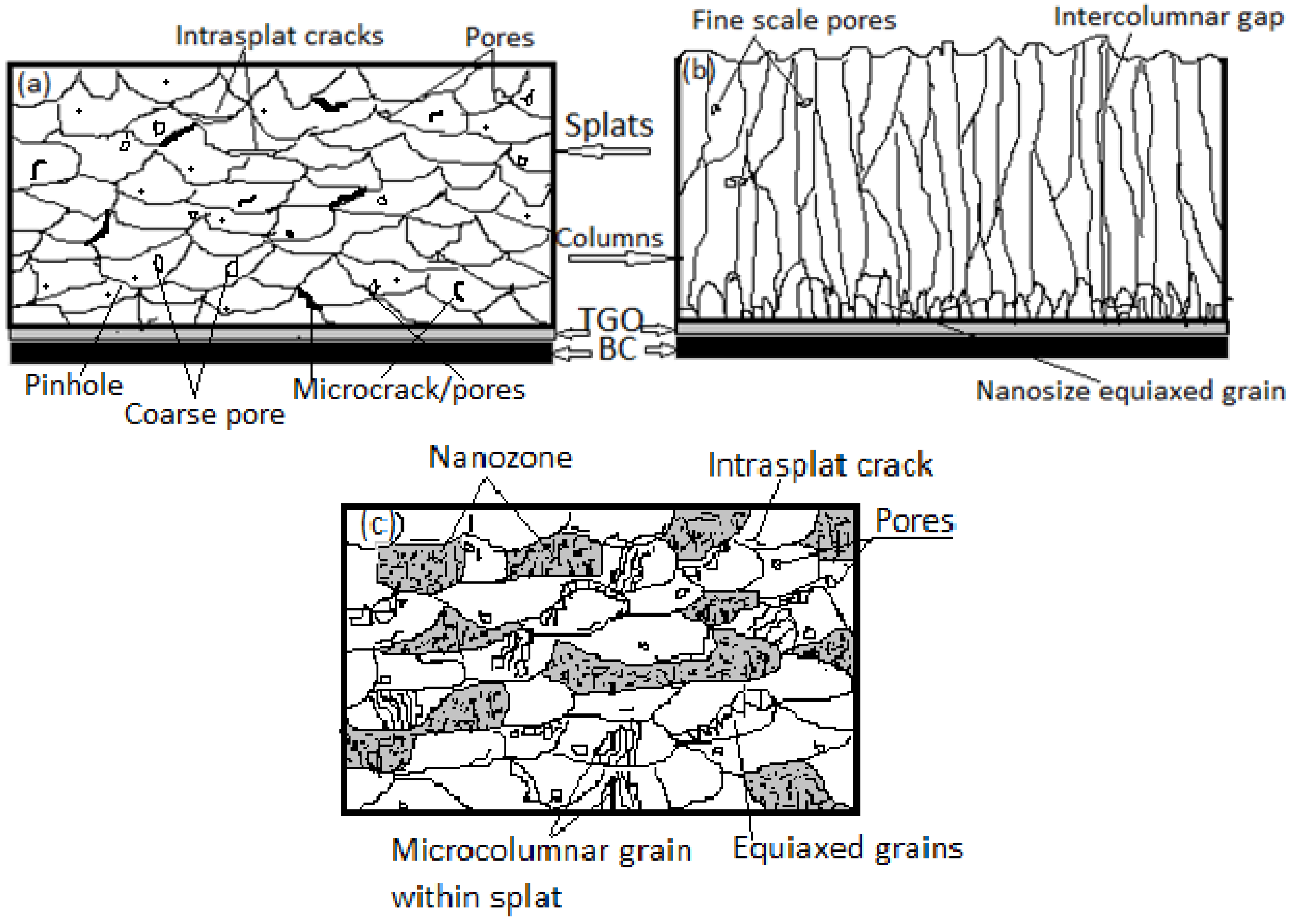
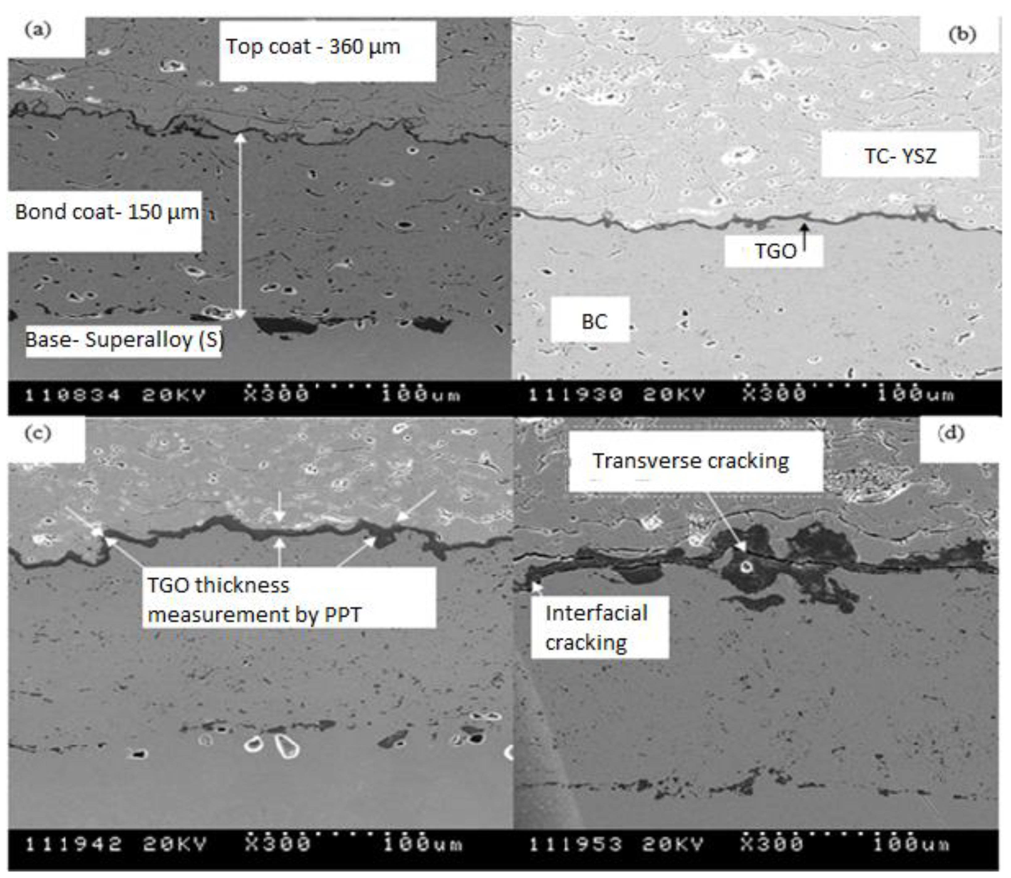
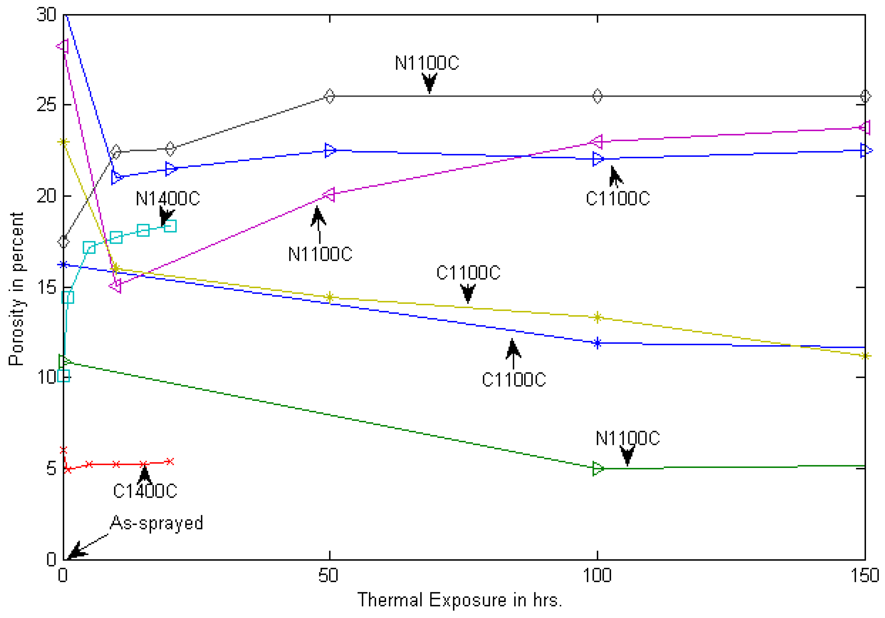
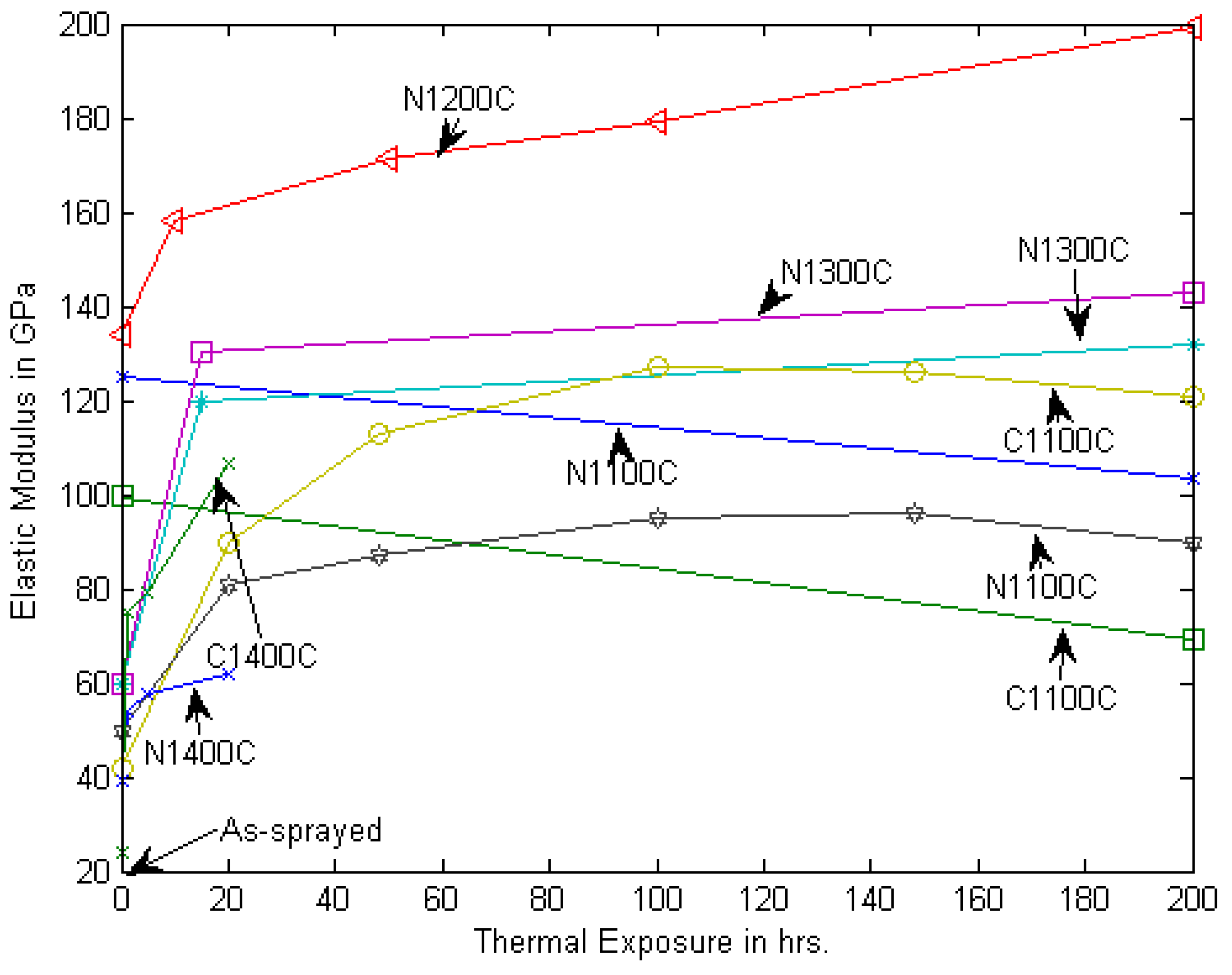
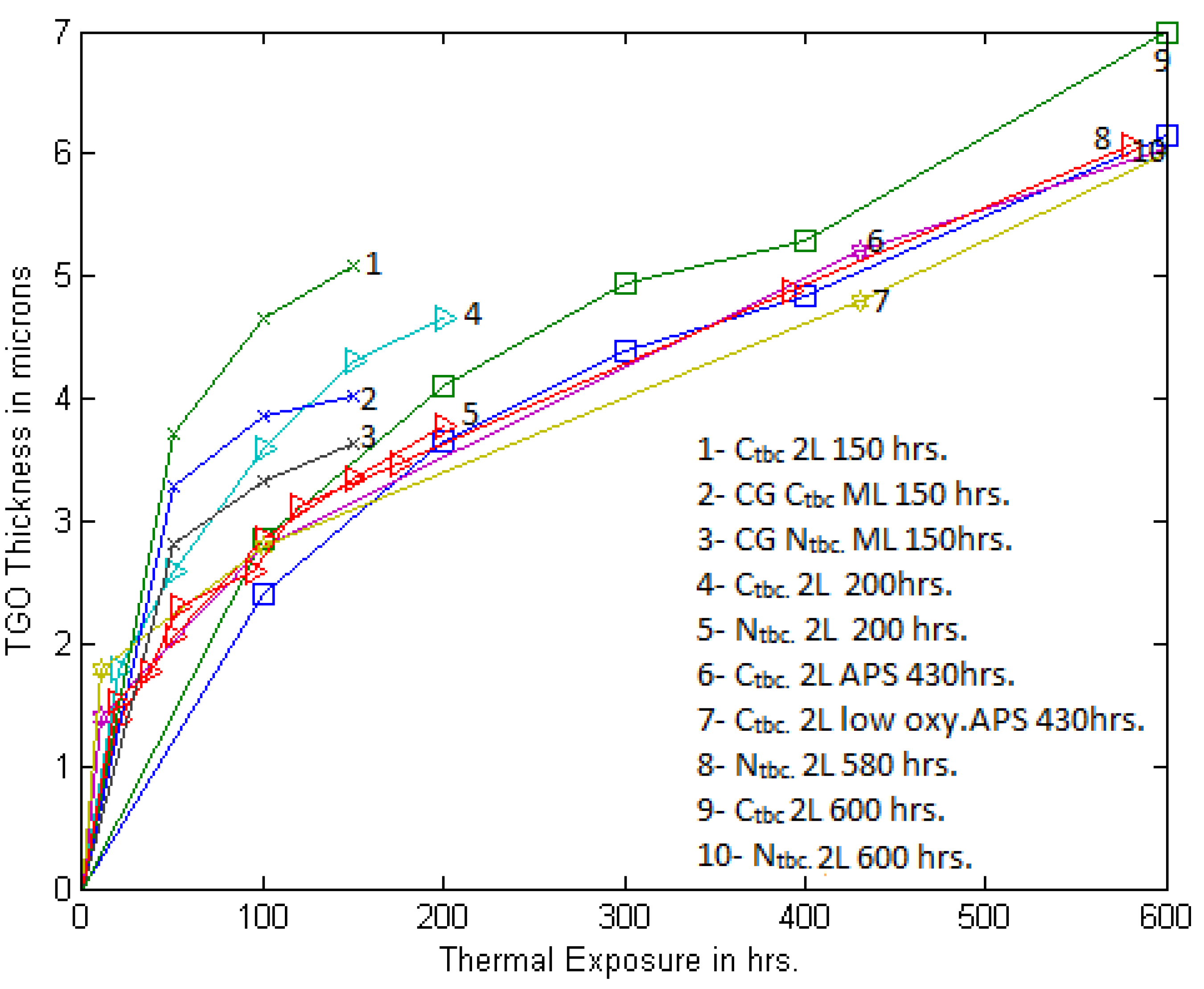
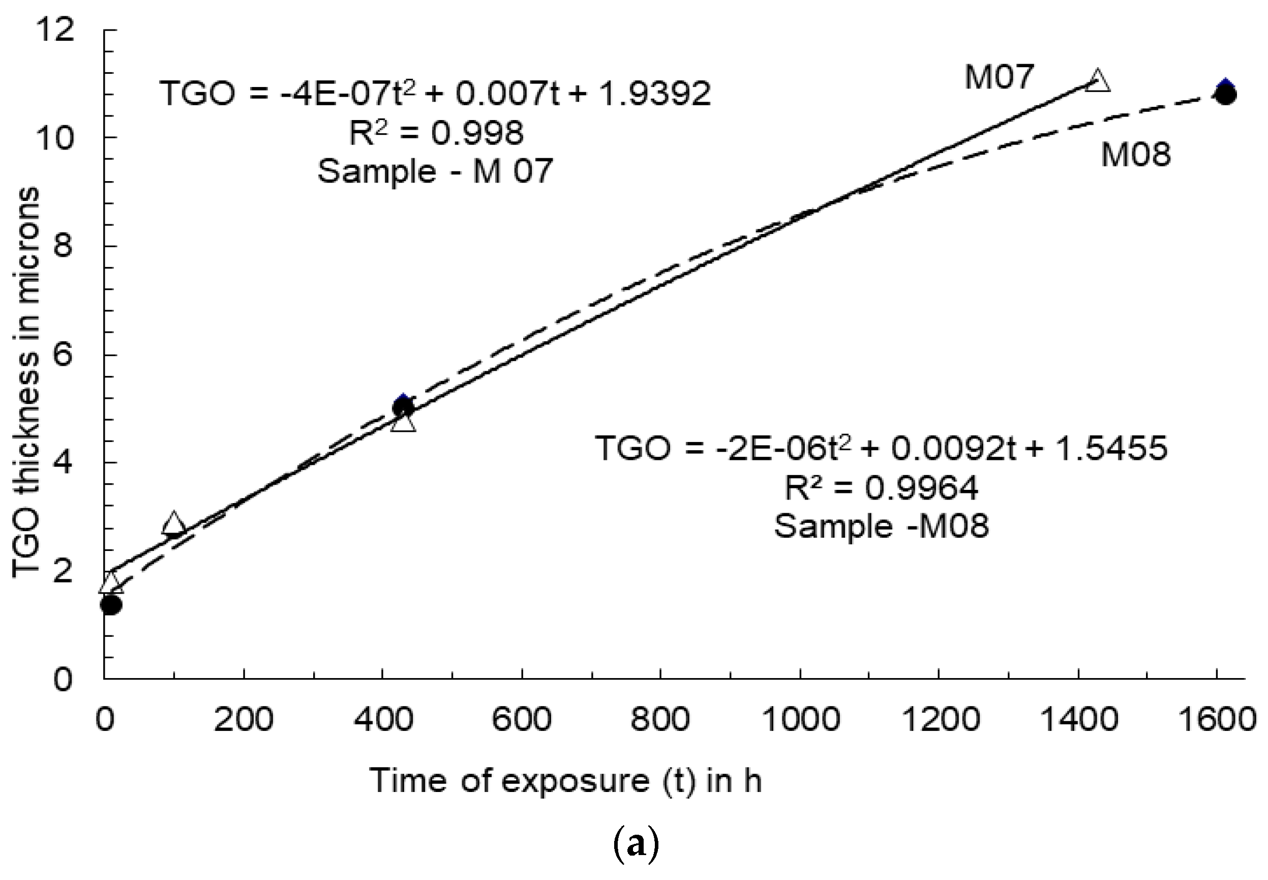
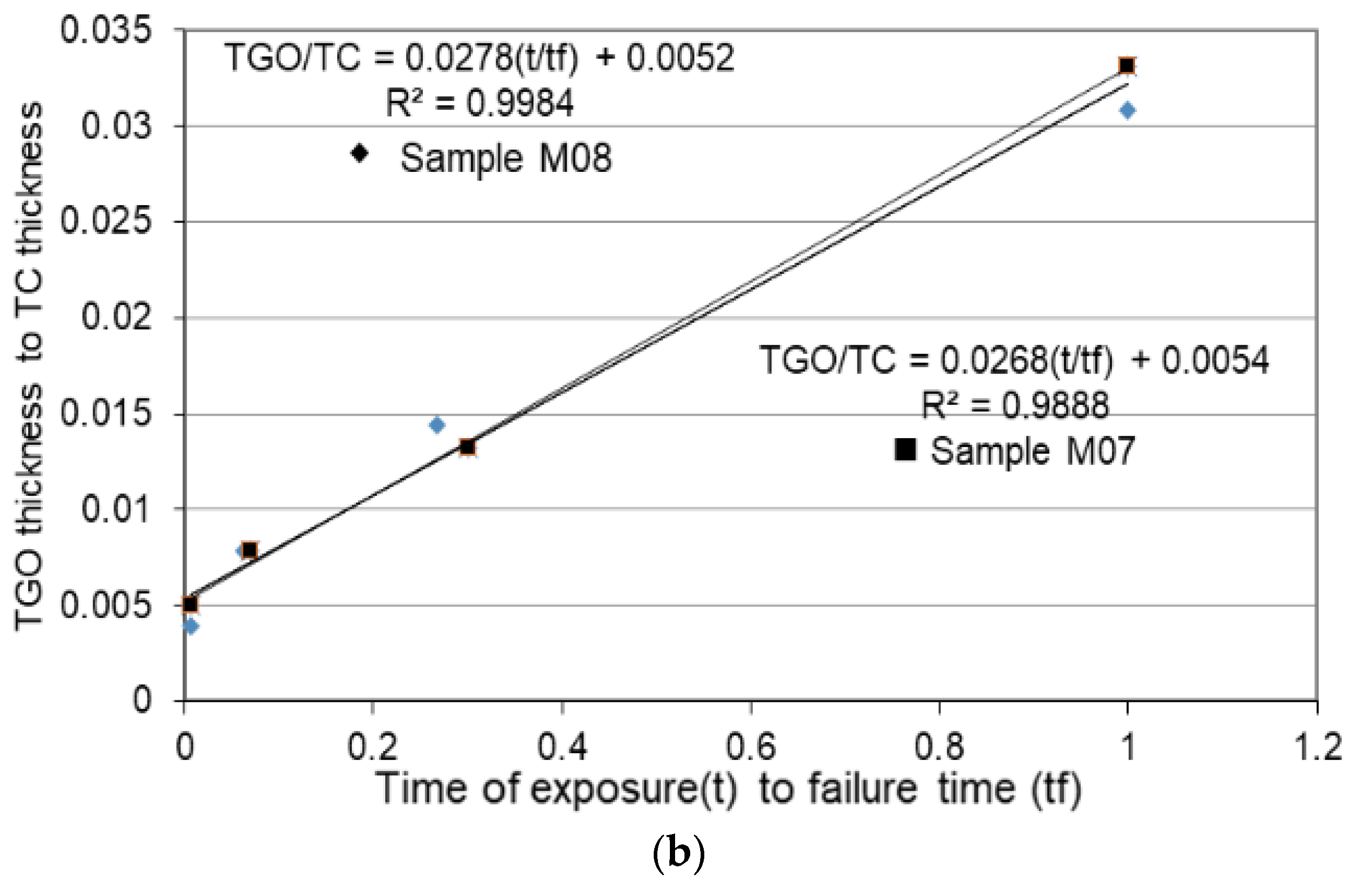


Publisher’s Note: MDPI stays neutral with regard to jurisdictional claims in published maps and institutional affiliations. |
© 2021 by the authors. Licensee MDPI, Basel, Switzerland. This article is an open access article distributed under the terms and conditions of the Creative Commons Attribution (CC BY) license (https://creativecommons.org/licenses/by/4.0/).