Abstract
Many prints are coated to increase their resistance or to enhance their appearance. Applying a smooth transparent layer on a print darkens and saturates its color, an easily observable effect which can be predicted in order to obtain better color management of coated surfaces and ink saving. A model was thus developed which describes the reflectance of a single-ink line halftone in optical contact with a transparent smooth coating. It is based on the peculiar way light diffuses inside the coating layer, a phenomenon called the “halo effect”. The model was compared to two experiments conducted at different scales where line halftones were coated with different coating thicknesses. The experiments enabled us to identify and measure the darkening effect caused by a coating layer, and validated the model.
Keywords:
halftone; coating; reflectance; halo effect; point-spread function; transparent layer; print 1. Introduction
Many printed surfaces and documents are protected by a transparent layer of varnish or resin, by coating, printing, calendering or lamination processes [1,2,3,4]. It is in particular the case for secured documents and cards, where an overlay is laminated on top of the printed surface [5,6,7]. The coating materials are usually acrylic or photo-curable varnish [8,9], PET, PE or PP laminates [10]. On an optical point of view, the coating material has not much importance, except its refractive index, absorption coefficient and surface topology which can however have a strong impact on the print appearance, especially on the color gamut [11,12,13] and the glossiness [14,15,16,17]. These changes of appearance can first be explained by a change of surface topology of the material, since adding a coating layer can smoothen the surface of the material and reduce light scattering on it [18,19], or, on the contrary, increase the surface scattering [20]. The refractive index of the air–matter interface may also be modified by the presence of coating, and colored surface reflection due to bronzing of inks [21] can disappear, thus changing the overall color appearance. The color is also changed if the coating itself is colored: selective absorption of light occurs within the coating layer to a stronger extent as the thickness increases. Lastly, the coating induces a multiple reflections process between the diffusing support and the air-coating interface [22], process that the classical Williams–Clapper model considers when the coated support has a uniform reflectance and is wholly illuminated [23,24]. Actually, this multiple reflection process relies on a very specific ring-shaped point-spread function depending on the coating’s refractive index and thickness. This ring-shaped halo was first observed by Cornu on coated photographs [25] and is also observed through oceans in laser bathymetry [26]. An optical model has been recently developed for the phenomenon in the case where the support is homogenous [27], and preliminary observations performed by some authors of the present paper have shown that it may have strong consequences on reflectance, thereby on color, when the support has a non-uniform reflectance [28]. This halo effect is comparable to the dot gain effect which is caused by light diffusion inside the substrate [29], as both phenomena can be modeled by point-spread functions whose shapes are however very different. If the effect due to scattering within diffusing printing supports has generated a profuse literature [30,31,32,33,34,35,36,37,38], it seems that the halo effect due to a transparent coating has never been evocated as such in literature, neither theoretically or experimentally. Of course, the two optical dot gain effects can add mutually, and this is a possible reason why the halo effect has not been clearly identified (it has been noticed in [12,13] that a glossy coating introduces additional dot gain but no physical explanation is provided). There is therefore no available information indicating to what extent the phenomenon, independently of other phenomena, contributes to the global dot gain effect, and to which extent and in which conditions the coating, even perfectly clear, can modify the halftone colors. This is precisely what we would like to determine, by focusing specifically on the halo effect alone in absence of dot gain due to the diffusing support. We also want to estimate its impact on the spectral reflectance and the color of halftone prints as functions of the coating thickness, whether the coating is absorbing or not. The approach that we adopt in this paper is first to address the theoretical aspects: we briefly remind the classical Williams–Clapper reflectance model which applies with uniform diffusing supports coated with a transparent layer, and straightforward extensions to non-uniform supports when the colored patterns are either very large or very small compared to the coating thickness (Section 2); we also expose a novel model incorporating the multiple convolutive process happening within the coating layer when the printed patterns have an intermediate size (Section 3). We then propose two experimentations conceived in order to verify the accuracy of the model, based on periodical line halftone patterns, at two different scales: a centimetric scale (Section 4) and sub-millimetric scale (Section 5). Comparisons between predicted and measured spectral reflectances are discussed in each case, and general conclusions are given in Section 6.
2. Background: Reflectance of Diffusing Supports Coated with a Transparent Layer
The Williams–Clapper model is a deterministic optical model, which describes the reflectance of a Lambertian surface covered by a transparent layer (originally a gelatin layer for photographic prints). It introduces four parameters, rs, ri, Tin, and Tout, which represent the flux transfers at the interface with air, featured in Figure 1a. The reflectance rs represents the portion of incident light externally reflected by the interface and captured by the observer or the detector. The transmittance Tin represents the portion of light entering into the substrate. The reflectance ri represents the portion of (diffuse) light internally reflected by the interface, and the transmittance Tout represents the portion of light emerging from the substrate in direction of the observer or detector.
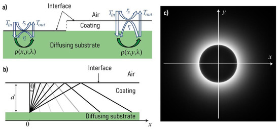
Figure 1.
(a) Light interactions at the interface between air and a diffusing substrate without and with transparent coating (coating and substrate have the same optical index); (b) internal reflections of rays emitted by one point on the substrate at the air–coating interface; the gray levels of the reflected rays depict the Fresnel angular reflectance for a refractive index of coating of 1.5 (light gray means low reflectance, black means total reflectance); (c) irradiance map due to the rays internally reflected at the air–coating interface, at the origin of the ring-like halo displayed in Figure 2, when the coating is non-absorbing. This map is a density plot of function h(x,y,1) defined in Equation (6).
They can be derived from Fresnel angular reflectance and transmittance of the interface, denoted by , respectively , when light incomes at angle from air (labeled 0, with a refractive index ), and , respectively , when light incomes at angle from the coating (labeled 1, with a refractive index ). For a di:8° measurement geometry, they are given by [29]:
where t denotes the intrinsic transmittance of the coating layer. It corresponds to the transmittance of the layer from one interface to the other, light traveling in the direction of the normal of the interfaces. In case of a non-coated area or a perfectly clear coating, t is 1. Otherwise, it depends on the coating thickness d and the absorption coefficient α at the wavelength , according to Beer’s Law:
In practice, reflectance measuring instruments do not deliver a reflectance but a reflectance factor where the radiance captured from the sample is divided by the one captured from a perfect white diffuser [39] which is equal to . Consequently, the term disappears in the expressions for and .
The reflectance factor R of a Lambertian substrate coated with a transparent layer, with respect to the perfect diffuser, is described by the Williams–Clapper model [23] or more exactly by its extension by Shore and Sponhower for the d:8° measuring geometry [24]:
where ρ(λ) is the spectral intrinsic reflectance of the substrate depending on wavelength λ. In the following, the dependence upon the wavelength will be omitted in the equations.
This model can be extended to halftones of intrinsic reflectance ρ0 for non-inked areas and ρ1 for inked areas with:
where, Ra is the reflectance of the halftone of surface coverage a.
Equation (3) is valid only if the inked and non-inked areas are large enough with respect to the thickness of the coating, so that they represent uniform areas with no light interaction at the optical scale. The halftone must also be viewed from a distance so that the global reflectance is the weighted average between the inked and non-inked area reflectances.
Equation (2) can also be extended to the opposite case where the inked and non-inked areas are so small with respect to the optical scale that they can be considered as a uniform area of intrinsic reflectance:
3. Extension to Halftone Prints: Multi-Convolutive Model
In an intermediate situation, i.e., if the inked and non-inked areas are in the size range of the thickness coating, a spatial phenomenon of halo-shaped light diffusion inside the coating cannot be ignored anymore. This convolutive halo phenomenon is thoroughly described in [27] for a uniform substrate. It takes place in a transparent layer, i.e., a non-diffusing but possibly absorbing material. One side of the layer is in contact with air. This interface is assumed to be flat and can be considered as a perfectly specular reflector. The other side of the layer is in contact with a very diffusing material behaving like a Lambertian reflector. The Lambertian reflector and the transparent layer are in optical contact, meaning there is no air or specular interface between them.
A light pencil illuminating a point of the Lambertian reflector is scattered inside the coating and reflected by the coating-air interface in a proportion depending on the Fresnel reflectance (it is rather weak at low incidence angle, and becomes 1 beyond the critical angle around 40°–50° according to the layer’s optical index). Light then propagates back toward the Lambertian reflector. The irradiance map on the Lambertian reflector draws a ring-like halo (see Figure 1b,c) whose diameter depends on the thickness of the coating.
Each point reilluminated on the Lambertian reflector again generates a comparable ring-like halo, and this occurs multiple times. The halo is therefore convoluted an infinite number of times with itself (see Equation (10)). This gives, at the end of the process, another ring-like halo illustrated by Figure 2 (left image).
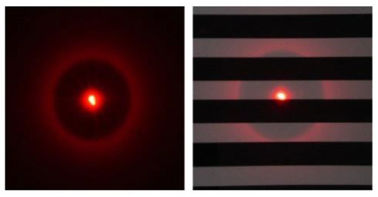
Figure 2.
Pictures of the point-spread function of a uniform substrate (image on the left) and a substrate with line-halftone black and white pattern (image on the right) both coated with a clear layer, as displayed when illuminated with a red laser beam.
When the sample is uniformly illuminated over a very large area, each point generates a halo but all halos overlap each other and they are not visible anymore. However, they have an effect on the sample’s color if the Lambertian reflector is not uniformly colored.
In the case of non-uniformly absorbing substrates, such as paper printed with a line halftone pattern as shown in Figure 2 (right image), the halo phenomenon increases the probability for light to be absorbed by the ink. This occurs to a higher extent as the material is more absorbing.
Thus, prints can appear darker when they are coated with a clear layer, and their color is also more saturated since the difference in reflectance values in the spectral domains where the ink is the most and the less absorbing is increased. As shown in [28], these effects depend on the size of the halo, thereby on the layer thickness, in respect to the size of the halftone patterns.
A new reflectance model has thus been recently developed considering this halo-shaped light diffusion. The equations are detailed in [28] in the case of a clear, non-absorbing coating. We extend them here to account for the transmittance of the varnish layer. To simplify the model, the considered halftone is composed of a periodic pattern of inked and non-inked lines of which the relative widths are proportional to the surface coverage of the halftone. It is displayed Figure 3a, with p the period of the halftone, a the surface coverage and the intrinsic reflectance ρ0 for non-inked areas and ρ1 for inked areas.
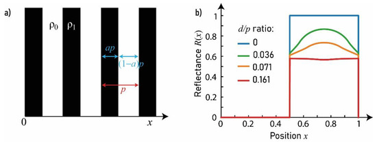
Figure 3.
(a) Line halftone pattern and parameters associated; (b) local reflectance profile as a function of position x for different d/p ratios.
The intrinsic reflectance ρ of the halftone varies only along the x-axis and can be described as:
Let us coat the print with a clear layer whose interface with air is smooth (it thus has a glossy aspect). The substrate-coating interface has no optical effect as the difference of optical indices between the coating and the support is small. The substrate is assumed to be a Lambertian surface without internal diffusion. The irradiance, h, of the substrate produced by the halo, assuming that the initial irradiance at the central point is unity, depends on the intrinsic transmittance of the coating layer, , according to the following expression:
where d is the thickness of the coating layer. This function is shown in Figure 1c when the coating is non-absorbing. The diameter of the ring in the halo, , defined by the maximum value of irradiance , is given by:
We can verify that the flux contained in the halo, divided by the flux emitted by the central point assumed to be unity, is independent of d and coincides with the internal reflectance of the interface:
The print is uniformly illuminated. The incident irradiance, E, assumed to be unity, crosses the interface (transmittance Tin), then strikes the substrate. Each point of the support receives the same irradiance and reemits an exitance according to the local intrinsic reflectance , which produces a halo that reilluminates the substrate with an irradiance defined in every point as:
where symbol denotes the 2D convolution operator. Each point reemits an exitance , which produces again a halo reilluminating the substrate, and so on. The successive exitances satisfy the recursive equation:
We can show that beyond k = 10, the exitance is close to zero and the total exitance which is the sum of all exitances , can be approximated by the corresponding truncated sum. Therefore, the radiance observed from a certain direction, after crossing the interface (factor Tout), is given by:
The reflectance factor of the coated print—as viewed from a large distance—is the external reflectance, rs, plus the internal contribution given by the average value of radiance over the whole surface area A, divided by the radiance 1/π scattered by a perfect white diffuser in same direction and under same unit irradiance E:
For line halftones, the intrinsic reflectance of the material varies only along the x-axis. During its implementation, the model can then be simplified to a unidimensional problem. The integral of the ring-shaped function h is calculated along the y axis and is used inside the convolution operation. This convolution is then performed only along the x axis. Predicted reflectance can then be retrieved as a function of the wavelength and the x-position, or, by integrating over the x axis, as the global reflectance of the area, .
In the end, the multi-convolutive model allows us to determine the reflectance of a coated line halftone, knowing the input parameters: the surface coverage a of the non-coated halftone; the ratio d/p between the thickness of the coating layer, d, and the period of the halftone, p; the intrinsic reflectance ρ0 of the bare substrate; the intrinsic reflectance ρ1 of the full-tone; the optical index n1 of the coating material; the transmittance t of the coating layer and the terms , , , and which are dependent of the measurement geometry. Once all parameters are set except the d/p ratio, it can be shown that the reflectance decreases as this ratio increases. This can be visualized in Figure 3b, where the reflectance profiles of the halftone pattern along the x axis, predicted by the model, are plotted for various d/p ratios. The profiles being periodical, only one period is shown. In this simulation, the substrate has ideal reflectances: and , the coating is perfectly clear: t = 1, the coating’s refractive index is 1.5, the terms , , , and correspond to a de:8° measurement geometry (specular component excluded), the surface coverage of the halftone pattern is a = 0.5.
In absence of coating, the reflectance profiles computed without coating have a reflectance of 0 in the inked area and 1 in the non-inked area. As d/p increases, the reflectance of the non-inked area decreases: the probability for light to meet a neighboring inked area, therefore to be absorbed, increases. The halftone thus appears darker, as we will show later through pictures taken in an experimental verification step (see Section 4.3.). The shape of the reflectance profile also varies with d/p as light is reflected back towards the halftone at different positions of the periodic pattern.
4. Experimental Verification: Large Scale Halftone Patterns
The objective is to verify the model (Equations (10) and (12)) by comparing it to an experiment where the halo effect is the only optical phenomenon having an impact on the measurements.
4.1. Materials and Characterization
In order to avoid any confusion between this effect and dot gain due to light diffusion within the substrate, we chose a configuration where the halftone patterns are very large in comparison to the significant size of the substrate’s point-spread function. The line halftone pattern has a period of 33.3 mm, composed of large black and white lines. A liquid was gradually poured on the halftone to generate multiple thicknesses of clear coating layers. For each coating thickness, the halftone was captured through a camera. Each thickness was derived from the size of the halo generated by a laser beam and captured with a handheld camera. The experimental setup is displayed in Figure 4.
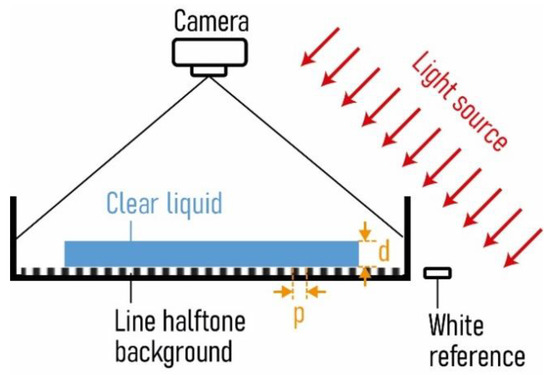
Figure 4.
Experimental setup.
The halftone had to be waterproof and of significant scale. It was thus conceived by sticking alternatively black and white parallel tape bands over a white Teflon plate. The Teflon plate was 0.46 m long and 0.33 m wide. The tapes were electrical insulation tapes. The black tape was from BizLine and had an original width of 19 mm. The white tape was from McKenzie and had an original width of 15 mm. The halftone was placed at the bottom of a transparent basin. It was set horizontally on the ground with a bubble level. A white Lambertian diffuser, a spectralon, was placed next to it to be used as a white reference. The clear liquid which was poured over the halftone was a blend of water and sugar at saturation. The liquid is considered to have an optical index of 1.5.
The halftone and its surroundings were illuminated by a punctual light source set at 1.35 m from the middle of the halftone in the horizontal direction, and 1.5 m high. It thus formed an angle of 42° from the normal of the centre of the halftone. The light source was composed of two optical fibres without collimator linked to the same generator (from Micro-contrôle 154, division Nachet). A red filter inside the generator provided a light of bandpass higher than 650 nm, measured by a goniospectrophotometer (Eta Optik CG100 Goniometric Color Measurement System).
The halftone was captured with a camera Sony α6000 which was set at 0.3 m from the middle of the halftone in the horizontal direction, and at 1 m in the vertical direction. It thus formed an angle of 16.7° with the normal at the middle of the halftone. The camera was set, in the azimuth plan, perpendicularly to the direction of the light from the source to avoid capturing diffuse reflection on the halftone. The parameters of the camera were: ISO 400, completely open diaphragm, 8 s exposure time, focus around 1.7 m, zoom at 35, RAW picture format. The sensor had a 14-bit encoding. The linearity of the sensor with exposure time was verified. The values given by the sensor of the camera in the complete darkness were captured through 11 pictures, their mean values were calculated to get the black frame picture. As the illuminating light is red, only the red channel of the Bayer matrix of the camera was considered. Its sensitivity was considered to be low above 720 nm, thus the wavelength bandpass of the system was considered to be between 660 and 720 nm. For each measurement on the halftone, two pictures were taken and the mean of them was used in the data treatment. An illumination map was also captured by imaging with the camera the same area as for the halftone but with a uniform paper substrate.
For each coating thickness, a data treatment was made to retrieve, from the pixel values of the camera, the reflectance factor of the halftone. First, all the pictures from the camera were cropped to put the focus on two zones of the pictures: the halftone and the white reference. The halftone zone was delimitated to have a zone with an integer number of periods, completely covered by coating (except in the first picture without coating), and where the illumination is regular (in the middle of the halftone and with a small number of periods). The white reference zone was as large as what was allowed by the captured circular spectralon. The illumination map and the black frame were also cropped according to these two zones. The cropped pictures from the illumination map were blurred to remove the noise induced by the grain of the paper used as uniform substrate. The blur was made through a convolution with a Gaussian function. The pixel values of the halftone and of the white reference were calibrated with considerations of the black frame and the illumination map with:
where denotes the calibrated pixel values in the halftone area, the pixel values of the halftone, the pixel values of the black frame in the halftone area, the pixel values of the blurred illumination map in the halftone zone. The same operation was performed for the white reference zone, with the calibrated pixel values of the white reference area, the pixel values of the white reference, the black frame pixel values in the white reference area and the pixel values of the blurred illumination map in the white reference area.
From these calibrated values, we can deduce the reflectance factor of the halftone for each pixel position with:
where R is the reflectance factor of the halftone at each pixel position, the calibrated pixel values in the halftone zone, the average calibrated pixel value over the white reference zone and the average reflectance of the white reference over the range of wavelengths (660–720 nm). This reflectance was measured with the spectrophotometer CM-2600d from Konica Minolta (geometry: de:8°, 8 mm aperture, without UV cut-off filter).
4.2. Computational Method
The model was calibrated as follows. The surface coverage of the halftone was first determined. It was measured on pictures of the halftone with ImageJ software by measuring the width of the black tape, in number of pixels, and dividing it with the width of the period. Eleven measurements were made and the results is a = 0.551 ± 0.011. This surface coverage matches the one determined by thresholding the reflectance picture of the halftone zone without coating. The period of the halftone was measured over nine periods, and we determined that p = 33.3 ± 0.2 mm. The thickness of the clear layer was determined by measuring the diameter of the dark disk in the halo in images: for each thickness, a picture was taken of the halo generated by a thin laser beam. The scale of each picture was determined in the ImageJ software using the averaged size of one period (in pixel) over five measurements. The area of the dark circle A of the halo was measured on the scaled image with ImageJ software. From this area, and considering the optical index of the clear layer to be n1 = 1.5, we determined the thickness d thanks to the following formula issued from Equation (7):
This was repeated twice and the considered result was the average of the two values obtained for d.
The intrinsic reflectances of the white tape, , and the black tape, , were determined from the measured reflectance of, respectively, the white and the black tapes without coating by using the following equation [40]:
The reflectance measurements were made with the spectrophotometer CM-2600d from Konica Minolta (geometry: di:8°, 8 mm aperture, without UV cut-off filter).
The coating layer is considered to be perfectly transparent (t = 1) and with an optical index of 1.5.
Parameters , , , and were calculated for the specific geometry of the experiment: directive illumination with an angle of 42°, and measurement with an angle of 16.7°.
The mean reflectances given for each thickness by the model were calculated over the spectral range 660–720 nm.
4.3. Result and Discussion
We compared the reflectance factors measured for each coating thickness with the ones predicted by the model for the same thicknesses. Some of the experimental spatial reflectance factors are displayed Figure 5a. It can be seen that as d/p increases (d thickness of the coating layer, p period of the halftone which is constant), the reflectance of the white bands decreases. Pictures also look blurrier when a coating layer is applied. The decrease in reflectance of the samples due to the coating layer can be seen in the diagram of Figure 5b showing the average reflectance factor over the picture as a function of the d/p ratio. The vertical error bars represent the mean standard deviation of each spatial reflectances calculated for each column over all the lines, for each measurement. The predictions given by the model are also plotted (except for d/p = 0). The experimental and theoretical reflectances values match rather well and show the darkening effect due to the diffusion of light inside the coating layer. Even though we took care in the experiment to verify the assumptions on which the model relies, real materials hardly meet the ideal properties that the model considers: the substrate was probably not a perfectly Lambertian reflector, and the optical index was close to 1.5 but maybe not precisely this value.
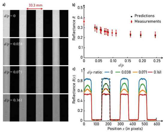
Figure 5.
(a) Pictures of the halftone pattern when uncovered and covered by a layer of clear liquid (optical index of 1.5) with increasing thickness, yielding four different d/p ratios; (b) comparison between measured and predicted reflectances of the coated support for different d/p values; (c) reflectance profiles extracted from the images displayed in (a) for the different d/p values (colored solid lines) and profiles predicted by the model for the same d/p values and the same reflectance values on the uncoated support (black dashed lines).
The large-scale experiment allows us to detect the effects of a coating layer on the reflectance spatial distribution of the halftones. Experimental and theoretical reflectance profiles of the halftone are thus plotted in Figure 5c. The experimental profiles are the average profile over 100 horizontal lines in the images, which reduced the noise. It can be seen that the experimental and theoretical profiles match fairly well despite the differences which might exist between the ideal materials considered in the model and the real ones used in the experiment. In the picture corresponding to a ratio d/p = 0.038, the edges between the white and black area look blurred. This blurring effect is a rather logical consequence of the multi-convolutive phenomenon that we analyze, and it can be easily observed with any coated print (examples are shown in [28]); surprisingly, this blurring effect that affects every laminated print, such as ID cards, is not reported anywhere in the literature.
5. Experiment Verification with Small Halftone Patterns
A second experiment was carried out to verify the multi-convolutive model in conditions which are closer to the printing domain, and compare it with other classical optical models.
5.1. Materials and Characterization
Halftone line patterns were printed with magenta ink on a coated paper. Seven patches were considered: one patch of bare substrate, one patch of solid magenta-inked substrate, and five patches of nominal coverage 0.5 with different line periods: 1.69, 1.35, 1.02, 0.85 and 0.68 mm. The halftones were printed with a Xerox printer of resolution: 1200 dpi (dot diameter of 21 µm), the printing resolution was 600 dpi.
The samples were first pasted onto a rigid substrate to prevent bending during the coating process. They were then coated with one to three layer(s) of varnish. The varnish was a UV curing varnish (Vernis Séricol sérigraphie, Omniplus UL, UL360, Application varnish, e 5 kg 54 BN777642, UN 3082, Fujifilm, Broadstairs, United Kingdom). It was applied with a thread bar (Mayer bar n°4, black handle, made for 40 µm deposit) from K control coater. The Mayer bar was at maximal speed and the coater was calibrated for twice the thickness of the samples, to ensure that the varnish layers were of significant thicknesses and had a flat surface. Each coating layer was polymerised with a conveyor from Distrilampe illuminating the sample with UV light. Before coating and after each varnish layer deposition, the thickness of each patch was measured, including the rigid substrate, and the reflectance of each patch was measured twice. The reflectance measurements were made with the spectrophotometer CM-2600d from Konica Minolta, based on the di:8° measurement geometry, delivering spectral reflectance from 400 to 730 nm in steps of 10 nm. There was a UV cut-off filter to prevent any fluorescence effect. The thickness measurements, performed with a micrometer from Adamel Lhomargy, allowed estimating the local thickness of the coating layer over each patch. The varnish thickness of each layer averaged over all the patch was, respectively: 61, 107 and 191 µm.
5.2. Computational Method
The measured reflectances were compared with classical reflectance models, the spectral Neugebauer model and Yule–Nielsen modified spectral Neugebauer model [40], as well as the multi-convolutive model (Equations (10) and (12)) introduced in the previous sections.
For single-ink halftones, the spectral Neugebauer equation is written [41,42]:
where a denotes the surface coverage of the ink, and , and denote, respectively, the reflectance of the bare paper, the reflectance of the inked paper and the reflectance of the halftone print. The Yule–Nielsen modified spectral Neugebauer model relies on the following equation [32,43]:
where a, , and have the same meaning as in the Neugebauer equation, and is a scalar parameter to be determined for each kind of sample (support, ink, printing system and halftone pattern or frequency).
We wanted to evaluate the performances of the different halftone reflectance models when the halftone is coated. To calibrate the models, the effective scalar surface coverage of each halftone, a, is needed. As the period of the halftones are large, the optical dot gain should not impact the determination of the surface coverages. They can thus be estimated by minimizing the deviation between the halftone reflectance measured, , and the one predicted by the spectral Neugebauer model, using the following equation:
These surface coverages are the input surface coverages of the three tested models (spectral Neugebauer, Yule–Nielsen modified spectral Neugebauer, and multi-convolutive model). The Neugebauer and the Yule–Nielsen models are based, for each layer, on the reflectance measurements of the bare substrate and solid ink covered with varnish coating. The parameter of the Yule–Nielsen model is fitted for each halftone reflectance measurement.
To calibrate the multi-convolutive model, d/p is determined by measuring the coating thickness and the halftone period in each sample. The intrinsic reflectances of the bare substrate, , and the solid magenta, , were determined from the measured reflectance of these patches without coating by using Equation (15). , , , and were calculated for the di:8° measurements geometry of the spectrophotometer. The coating layer is considered to have an optical index of 1.5. The varnish was transparent but it had a yellowish color. Its intrinsic transmittance was thus evaluated with the Williams–Clapper model from the reflectance measurements of the bare substrate for each coating layer. For each wavelength, the intrinsic transmittance is estimated through a linear interpolation from a 2D-lookup table of the Williams–Clapper model. This lookup table has two entries: the intrinsic reflectance of the substrate and the intrinsic transmittance of the varnish, each from 0 to 1 with a 0.001 sampling step. Its output is the reflectance of the coated bare substrate calculated with the Williams–Clapper model for the di:8° geometry. Knowing the experimental reflectance of the coated bare substrate and the experimental intrinsic reflectance of the substrate, the intrinsic transmittance of each coating layer can be deduced. It is then calculated for the local thickness of the layer over each halftone according to Beer’s law Equation (1).
5.3. Results
The spectral reflectance predicted by the Neugebauer, Yule–Nielsen and multi-convolutive models, as well as the measured ones, are plotted in Figure 6.
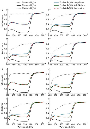
Figure 6.
Measured and predicted reflectances of magenta line halftones of period (a) 1.69 mm; (b) 0.68 mm, with different varnish thicknesses: without varnish (top left); one layer (top right); two layers (bottom left) and three layers (bottom right).
For the uncoated samples where the halftone patterns have the largest period, Figure 6a (top left), the reflectance predicted by the spectral Neugebauer model matches well to the measured reflectance. Optical dot gain has therefore little impact on the print reflectance and this justifies that the Neugebauer model was used to determine the surface coverage of the print. For the coated samples, the predicted spectral reflectances given by the Neugebauer model do not coincide with the measured one: the print is darkened due to the coating layer. The Yule–Nielsen modified spectral Neugebauer model is able to render this darkening thanks to the fitted parameter, which are displayed in Table 1 (and plotted in Section 5.4.). The darkening can thus be viewed as an optical dot gain caused by the coating layer. The multi-convolutive model also renders the darkening effect and approaches fairly well the measured spectral reflectances without any fitted parameter. The root mean square errors between predictions and measurement, given in Table 2, show that it is almost as accurate as the Yule–Nielsen model, known to be one of the most accurate reflectance prediction models for halftone prints [40]. The small spectral differences that can still be seen between the predicted and measured spectra in wavelength domain 500–600 nm are probably due to the fact that the solid magenta patch absorbs almost all the light in this spectral domain and the measured reflectance reaches a floor value. They can also be due to an effect of fluorescence by the paper.

Table 1.
Fitted parameter of the Yule–Nielsen model.
Table 2.
Root mean square error between the models and the measurements.
On a colorimetric point of view, the darkening effect due to the coating can be observed in Figure 7 in the CIE 1976 L*a*b* color space, where the coordinates associated with the different measured spectral reflectances are represented. These color coordinates were obtained by converting each spectral reflectance as well as the spectral reflectance of the bare paper into CIE 1931 XYZ tristimulus values by considering 2° observer and an illuminant E of uniform spectral power distribution over the visible spectrum. These tristimulus values were then converted into L*a*b* color coordinates with the bare paper as white reference for the chromatic adaptation. The color of each patch is represented with one point in the a*b* plane and in the L*C* plane, with a* denoting the green to red tones, b* denoting the blue to yellow tones, L* being the lightness and C* being the chroma, [44].
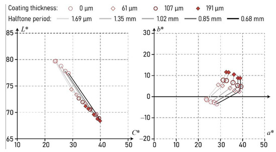
Figure 7.
CIE1976 L*a*b* colorspace.
It can be observed in the L*C* plane that, as the coating thickness increases, the halftone color becomes darker and more saturated, which is linked with the higher probability for light to meet a neighboring ink pattern. The a*b* plane shows that the color of the halftones also becomes more yellowish as the varnish thickness increases, which is due to the absorptance of the varnish.
5.4. Discussion
The darkening effect due to the presence of a transparent coating on top of halftone printed diffusing support is confirmed both theoretically and experimentally, and we have shown through the example of line halftones that it is predictable. The further question that arises is the error that we can do with classical models that ignore this effect in their calibration, i.e., in the estimation of the surface coverage of the ink patterns from reflectance measurements. In Figure 8a are plotted the apparent surface coverage of the coated halftones for various d/p ratios. The apparent surface coverages are estimated through the Murray–Davies equation and their average is calculated over the absorption wavelength range of the ink: between 400 and 620 nm. It can be seen that the coating layer induces an overestimation of the surface coverage, which is due to the fact that the Murray–Davies equation does not take into account light propagation inside the coating layer.
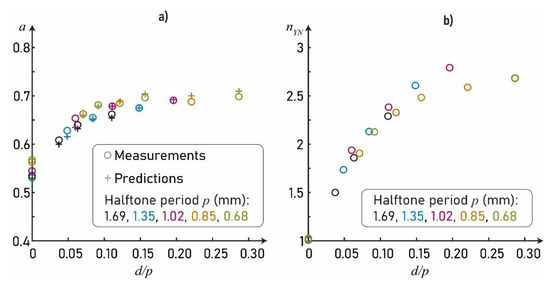
Figure 8.
(a) Apparent surface coverage estimated with the Murray–Davies equation; (b) fitted parameter of the Yule–Nielsen model.
We can also verify that the darkening effect can be considered as an optical dot gain effect. The parameter of the Yule–Nielsen model which is a marker of optical dot gain [31,40], is displayed Figure 8b as a function of the d/p ratio of each coated patch. We observe as expected that increases as d/p increases, which corroborates the trends evocated above.
6. Conclusions
Coating a non-uniform diffusing surface such as a halftone-printed support with a smooth transparent coating may have significant impact on its appearance: its color becomes darker [13] and more saturated. In color printing, this tends to increase the color gamut, as noticed in [11,12] without physical explanation. We show in this paper that these color changes are due to a lateral propagation of light within the coating during the multiple reflections process that occurs between the inked diffusing substrate and the coating–air interface. The consequences on the spectral reflectance and color of halftone prints are similar to the well-known optical dot gain effect due to scattering within the diffusing substrate, even though the point-spread function associated with this the lateral propagation of light is a ring-like halo, modeled recently in the case of uniformly colored supports [27], not a Gaussian or Lorentzian-like point-spread function as usually observed in diffusing supports [45,46]. We developed an optical model taking into account the multiple convolutions between the ring-like halo and the halftone screen pattern, and could verify its predictive accuracy thanks to an experiment based on large-line halftone patterns in order to isolate the dot gain due to the coating from the dot gain due to the diffusing substrate, the latter being negligible in this case. A second experiment based on single-ink-line halftone prints on paper could also shows the good accuracy of the model. The classical spectral Yule–Nielsen model can also provide good predictions of the spectral reflectance of the coated print, provided the coating is not absorbing too much, by means of fitting the empirical Yule–Nielsen often considered as a marker of lateral propagation of light within the print [30,31,32,33,34,35,36,37,38]. The value of this latter increases as the coating thickness increases, which confirms the idea that the phenomenon can be considered as a dot gain effect. For thick coatings (thickness greater than halftone period [28]), the model converges towards a limit similar to the Clapper–Yule model, where light travels such long distances in the coating that the spatial dimension of the halftone can be neglected [40,47]. A broader study could enable to find a fitting curve for which would enable us to use the Yule–Nielsen model to predict the coated halftone reflectances in an easier manner than with the multi-convolutive model. In a near future the objectives would be to extend this study to multiple-inked halftones, with different patterns, and take into account light diffusion inside the substrate to predict the reflectance of small-scaled coated halftones. The developed optical model could then be used for any application involving coated halftones, such as packaging or security printing.
Author Contributions
Methodology, M.H.; investigation, F.D.; writing—original draft preparation, F.D.; writing—review and editing, M.H., A.B., L.C. and T.F.; supervision, M.H., A.B., L.C. and T.F. All authors have read and agreed to the published version of the manuscript.
Funding
This work has been supported by a public grant from the French National Research Agency (ANR) under the Investments for the Future Program (PIA), which has the reference EUR MANUTECH SLEIGHT - ANR-17-EURE-0026.
Institutional Review Board Statement
Not applicable.
Informed Consent Statement
Not applicable.
Data Availability Statement
Data is contained within the article.
Conflicts of Interest
The funders had no role in the design of the study; in the collection, analyses, or interpretation of data; in the writing of the manuscript or in the decision to publish the results.
References
- Kipphan, H. Handbook of Print Media; Springer: Berlin/Heidelberg, Germany, 2001. [Google Scholar]
- Cigula, T.; Hudika, T.; Donevski, D. Color Reproduction on Varnished Cardboard Packaging by Using Lower Ink Coverages Due to the Gray Component Replacement Image Processing. Color Res. Appl. 2021. [Google Scholar] [CrossRef]
- Marques, J.; Pahl, B.; Kallmayer, C. Thermoplastic Packaging and Embedding Technology for ID-Cards. In Proceedings of the 2013 Eurpoean Microelectronics Packaging Conference (EMPC), Grenoble, France, 9–12 September 2013; pp. 1–5. [Google Scholar]
- Kucharska, J.K. Technical and Technological Analysis of Modern Methods of Printing Lamination; Instytut Mechaniki i Poligrafii: Warsaw, Poland, 2021. [Google Scholar]
- Dobrowolski, J.A.; Baird, K.M.; Carman, P.D.; Waldorf, A. Optical interference coatings for inhibiting of counterfeiting. Opt. Acta Int. J. Opt. 1973, 20, 925–937. [Google Scholar] [CrossRef]
- Posch, R. Protecting Devices by Active Coating. J. Univers. Comput. Sci. 1998, 4, 17. [Google Scholar]
- Schott, J.H. Optical Security Features for Plastic Card Documents. In Proceedings of the Optical Security and Counterfeit Deterrence Techniques II, San Jose, CA, USA, 1 April 1998; Volume 3314, pp. 294–298. [Google Scholar]
- Roffey, C.G. Photogeneration of Reactive Species for UV Curing; Wiley: Hoboken, NJ, USA, 1997; ISBN 0-471-94177-8. [Google Scholar]
- Wicks, Z.W.; Jones, F.N.; Pappas, S.P. Organic Coatings, Science and Technology; Wiley: Hoboken, NJ, USA, 1992; Volume 1, Film formation, components and appearance; ISBN 0-471-61406-8. [Google Scholar]
- Lindner, M.; Rodler, N.; Jesdinszki, M.; Schmid, M.; Sängerlaub, S. Surface energy of corona treated PP, PE and PET films, Its alteration as function of storage time and the effect of various corona dosages on their bond strength after lamination. J. Appl. Polym. Sci. 2018, 135, 45842. [Google Scholar] [CrossRef]
- Sakovic, B. Effect of different types of lamination on colour gamut and tone value increase of digital prints. Print. Future Days 2007, 2007, 199–203. [Google Scholar]
- Hoffstadt, J. Simulating color changes due to coating of offset prints. Conf. Colour Graph. Imaging Vis. 2004, 2004, 489–493. [Google Scholar]
- Galić, E.; Ljevak, I.; Zjakić, I. The influence of UV narnish on colorimetric properties of spot colors. Procedia Eng. 2015, 100, 1532–1538. [Google Scholar] [CrossRef]
- Hudika, T.; Majnarić, I.; Cigula, T. Influence of the varnishing “surface” coverage on optical print characteristics. Teh. Glas. 2020, 14, 428–433. [Google Scholar] [CrossRef]
- Childers, A.; Etheredge, A.; Flannery, S.; Freeman, J. Effects of Varnish on Printed Material; FlexoGlobal, Salmon Creek Publishing: Williamson, NY, USA, 2008. [Google Scholar]
- Czimbalmos, K.; Borbély, Á. Color Changes during the Production of Laminated Flexographic Prints. In Scientific, Technical and Art Releases—2020; Media Technology and Light Industry Institute of Rejtő Sándor Faculty of Light Industry and Environmental Engineering Óbuda University: Budapest, Hungary, 2020; pp. 11–15. ISBN 978-963-449-228-3. [Google Scholar]
- Aida, T. Glossiness of colored papers and its application to specular glossiness measuring instruments. Syst. Comput. Jpn. 1997, 28, 95–112. [Google Scholar] [CrossRef]
- Jiang, B.; Huang, Y.D.; Bai, Y.P. Noncontact and rapid analysis of the quality of the recording coating on ink jet printing by near-infrared spectroscopy. Analyst 2011, 136, 5157–5161. [Google Scholar] [CrossRef]
- Zhao, D.P.; Wei, X.F.; Huang, P.Q. Influence of promoter on the glossiness of water-soluble varnish. Adv. Mater. Res. 2011, 174, 441–444. [Google Scholar] [CrossRef]
- Hastreiter, J.J.; Simpson, W.H. Matte Finish on Thermal Prints. NIP Digit. Fabr. Conf. 2004, 2004, 976–979. [Google Scholar]
- Hébert, M.; Mallet, M.; Deboos, A.; Chavel, P.; Kuang, D.; Hugonin, J.-P.; Besbes, M.; Cazier, A. Exploring the Bronzing Effect at the Surface of Ink Layers; Proceedings of SPIE; The International Society for Optical Engineering: San Francisco, CA, USA, 2015; Volume 9398. [Google Scholar]
- Berns, R.S.; de la Rie, E.R. The Relative Importance of Surface Roughness and Refractive Index in the Effects of Varnishes on the Appearance of Paintings. In Proceedings of the 13thTriennal Meeting of ICOM Commitee for Conser-vation, Rio de Janeiro, Brazil, 22–27 September 2002; pp. 211–2016. [Google Scholar]
- Williams, F.C.; Clapper, F.R. Multiple internal reflections in photographic color prints. J. Opt. Soc. Am. 1953, 43, 595–599. [Google Scholar] [CrossRef]
- Shore, J.D.; Spoonhower, J.P. Reflection density in photographic color prints: Generalizations of the Williams-clapper transform. J. Imaging Sci. Technol. 2001, 45, 484–488. [Google Scholar]
- Cornu, A. Sur Le Halo Des Lames Épaisses, Ou halo photographique, et Les moyens de Le faire disparaitre. J. Phys. Theor. Appl. 1890, 9, 270–277. [Google Scholar] [CrossRef]
- Dolin, L.S. Laser Bathymetry Based on the Halo Effect. Appl. Opt. 2019, 58, 1555–1561. [Google Scholar] [CrossRef] [PubMed]
- Simonot, L.; Hébert, M.; Gerardin, M.; Monpeurt, C.; Fournel, T. Halo and subsurface scattering in the transparent coating on top of a diffusing material. J. Opt. Soc. Am. A 2018, 35, 1192–1203. [Google Scholar] [CrossRef] [PubMed]
- Hébert, M.; Dailliez, F.; Simonot, L. Why a Clear Coating Modifies Halftone Color Prints. In Proceedings of the IS&T Electronic Imaging Symposium, Material Appearance Conference, Online, 18 January 2021. [Google Scholar]
- Kriss, M. Handbook of Digital Imaging; John Wiley & Sons: Hoboken, NJ, USA, 2015; ISBN 978-0-470-51059-9. [Google Scholar]
- Rogers, G.L. Effect of light scatter on halftone color. J. Opt. Soc. Am. A 1998, 15, 1813–1821. [Google Scholar] [CrossRef]
- Rogers, G. Analysis of the yule-nielsen effect with the multiple-path point spread function in a frequency-modulated halftone. J. Opt. Soc. Am. A 2018, 35, 916–922. [Google Scholar] [CrossRef]
- Yule, J.A.C.; Nielsen, W.J. The penetration of light into paper and its effect on halftone reproduction. Proc. TAGA 1951, 3, 65–76. [Google Scholar]
- Ruckdeschel, F.R.; Hauser, O.G. Yule-nielsen effect in printing: A physical analysis. Appl. Opt. 1978, 17, 3376–3383. [Google Scholar] [CrossRef] [PubMed]
- Rogers, G.L. Optical dot gain: Lateral scattering probabilities. J. Imaging Sci. Technol. 1998, 42, 341–345. [Google Scholar]
- Arney, J.S. A Probability description of the yule-nielsen effect. J. Imaging Sci. Technol. 1997, 41, 633–636. [Google Scholar]
- Yang, L.; Lenz, R.; Kruse, B. Light scattering and ink penetration effects on tone reproduction. J. Opt. Soc. Am. A 2001, 18, 360–366. [Google Scholar] [CrossRef] [PubMed][Green Version]
- Yang, L.; Kruse, B. Ink Penetration and Its Effects on Printing. In Proceedings of the Color Imaging: Device-Independent Color, Color Hardcopy, and Graphic Arts V, San Jose, CA, USA, 21 December 1999; Volume 3963, pp. 365–375. [Google Scholar]
- Gustavson, S. Dot Gain in Colour Halftones. Image Processing Laboratory, Department of Electrical Engineering, Linköping University: Linköping, Sweden, 1997. [Google Scholar]
- Nicodemus, F.E.; Richmond, J.C.; Hsia, J.J.; Ginsberg, I.W.; Limperis, T. Geometrical Considerations and Nomenclature for Reflectance. National Bureau of Standards: Gaithersburg, MD, USA, 1977; p. 52. [Google Scholar]
- Hébert, M.; Hersch, R.D. Review of spectral reflectance prediction models for halftone prints: Calibration, prediction and performance. Color Res. Appl. 2014, 40, 383–397. [Google Scholar] [CrossRef]
- Neugebauer, H.E.J. Die Theoretischen Grundlagen Des Mehrfarbenbuchdrucks. Z. fur Wiss. Photographie. Photophys. Photochem. 1937, 36, 73–89. [Google Scholar]
- Neugebauer, H.E.J.; Wyble, D.; Kraushaar, A. The theoretical basis of multicolor letterpress printing. Color Res. Appl. 2005, 30, 322–331. [Google Scholar] [CrossRef]
- Viggiano, J.S. Modeling the color of multi-colored halftones. TAGA Proc. 1990, 42, 44–62. [Google Scholar]
- Fairchild, M.D. Color Appearance Models; John Wiley & Sons, Ltd.: Hoboken, NJ, USA, 2005; ISBN 0-470-01216-1. [Google Scholar]
- Rogers, G.L. Measurement of the modulation transfer function of paper. Appl. Opt. 1998, 37, 7235–7240. [Google Scholar] [CrossRef]
- Rogers, G.; Corblet, O.; Fournel, T.; Hebert, M. Measurement of the diffusion of light within paper. J. Opt. Soc. Am. A 2019, 36, 636. [Google Scholar] [CrossRef]
- Clapper, F.R.; Yule, J.A.C. The Effect of multiple internal reflections on the densities of half-tone prints on paper. J. Opt. Soc. Am. 1953, 43, 600–603. [Google Scholar] [CrossRef]
Publisher’s Note: MDPI stays neutral with regard to jurisdictional claims in published maps and institutional affiliations. |
© 2021 by the authors. Licensee MDPI, Basel, Switzerland. This article is an open access article distributed under the terms and conditions of the Creative Commons Attribution (CC BY) license (https://creativecommons.org/licenses/by/4.0/).