Article

Defect Formation Mechanism and Performance Study of Laser Cladding Ni/Mo Composite Coating

School of Transportation Science and Engineering, Civil Aviation University of China, Tianjin 300300, China
*
Author to whom correspondence should be addressed.
Coatings 2021, 11(12), 1460; https://doi.org/10.3390/coatings11121460
Submission received: 24 October 2021 / Revised: 18 November 2021 / Accepted: 26 November 2021 / Published: 28 November 2021
(This article belongs to the Special Issue Anti-wear Coatings for High Temperature Applications)

Abstract

:
In order to improve the wear resistance of Cu, a Ni/Mo composite coating was applied on the surface of Cu alloy by means of laser cladding. The laser power was 6000 W, the scanning speed was 5 mm/s and the feed rate was 10 g/min. The transition layer of the Ni layer had three layers, and the surface layer of the Mo layer had two layers. The results showed that the surface of the cladding layer was pure Mo. Due to the fluidity and non-equilibrium solidification of Mo in the molten state, pores and cracks along the grain boundary were observed in the Mo layer. The results showed that the cross-section of cladding layer was divided into a pure Mo layer, Mo-Ni-Cu mixed layer and an Ni-Cu mixed layer. The surface hardness of the Mo layer was 200~460 HV. Ni3Mo was formed at the interface of Mo and Ni. The hardness was improved by Ni3Mo; the maximum hardness was 750 HV. Under the same load and wear time, the wear rate of Cu was three times that of the surface layer.

1. Introduction

The electromagnetic gun is a typical electromagnetic launching device that uses magnetic force to accelerate projectiles to 2–3 km/s [1]. The wear resistance of the track has become the main problem faced by projects in this field. At present, the main form of failure of rails is scratching. Scratching refers to the shearing movement between rails at high speeds. When the yield strength of the rails cannot withstand huge impacts, the rails will cause shearing; groove slots are another form of failure of the rails. The grooves generally occur at the initial position of the launch and extend forward along the rails, leading to the failure of the rails [2]. Cu is the most commonly used material for electromagnetic gun rails. However, due to the low hardness of Cu, abrasion often occur on the surface. Wear leads to high operating costs and low efficiency of electromagnetic guns. Therefore, applying appropriate coatings on the Cu rails to improve the wear of the rails and ensure good thermal conductivity has become a research hotspot. Electroplating is a surface treatment method that uses the principle of electrolysis to deposit a coating on the surface of a substrate. The coating has the characteristics of small crystal grains, high hardness, and low friction coefficient. However, it produces a lot of industrial wastewater [3]. Cold spraying is another thermal spraying technology, which is based on the principle of aerodynamics. During the spraying process, particles collide with the substrate at a speed of 300–1200 m/s, and the coating is deposited by forming a strong plastic deformation. Therefore, it was found that the hardness was improved, the wear rate was decreased by 80% [2]. However, the effective deposition of particles and the preparation of stable high-quality coatings largely depend on the characteristics of the particles and the substrate material. Laser cladding [4,5,6] involves adding cladding material onto the surface of the substrate and using a high-density laser beam to clad the cladding layer to form a metallurgical coating. It has the characteristics of high power density, a small heat-affected zone, and rapid melting and cooling between the coating and the substrate. Therefore, it is widely used in the surface modification of metal materials. Because of the high reflectivity of Cu to lasers, it is difficult to perform laser cladding on the Cu surface. Many scholars have launched studies on this problem.
Some scholars have carried out related research on the conductive wear-resisting coating of laser cladding. Liu [7] carried out a study on H62 brass as a guide rail, which proved that the Cu guide rail had excellent thermal and electrical conductivity. However, it would cause serious wear, this failure of the Cu guide rail meant that it could not meet the requirements of the electromagnetic performance. In order to overcome the non-wear characteristics of the Cu alloy surface. Dong [8] prepared a cobalt-based coating on the Cu alloy surface to increase the surface hardness to 600 HV, which was six times the hardness of the Cu substrate. However, carbides were formed on the surface of the coating, and thus, a pure Co layer could not be guaranteed. In order to overcome the characteristics of oxidization at high temperature and low abrasion resistance, a high-temperature-resistant cermet coating was cladded on the Cu surface. Gu [9] chose the ceramic Pb3O4-B2O-BaO-SiO2 system to study the performance of the coating by changing the amount of Ni powder added. The results showed that the coating with the addition ratio of Ni powder to glass frit of 1.2:11.0 had the best overall performance. Besides, it could effectively protect the base alloy from oxidation. However, the hardness of the Cu surface was not significantly increased. Yang et al. [10] added Cr, Al, Sn, Ni and other elements to the Cu alloy. Yang added Cu particles and pure metal particles into the melting furnace, vacuumed and slowly flushed the contents with argon gas, and performed cold deformation treatment and a hardness test. The surface hardness of laser cladding was about two times that of Cu substrate. However, the thermal conductivity was reduced. Dehm [11] et al. first coated Cu powder with Ni-based powder and deposited a Ni-B-Si plasma spraying layer on the Cu substrate. Although the surface hardness was improved, a large number of borides fractured due to high stress in the cooling process. Due to the characteristics of rapid laser cooling, cracks were prone to occur on the surface of the cladding layer. Patrick W. Leech [12] performed laser cladding on the surface of composite high-alloy steel and found that pores and cracks extended from the surface to the bottom of the collective. The cracks could be reduced by controlling the laser power and scanning speed. Florian Wirth et al. [13] established a laser cladding simulation model to predict the height and width of the cladding, so as to achieve the purpose of process optimization. V.G. Smelov et al. [14] designed a laser sintering experimental device. By establishing a fine-powder laser sintering process algorithm, defect-free samples could be obtained, thereby obtaining a sintering zone without pores and cracks. However, the technology needed to produce a fine powder requires the use of expensive equipment.
At present, the main problem relates to how to improve the wear resistance and maintain the high conductivity of Cu rails. Mo has the characteristics of excellent high-temperature strength, high hardness, and high density. However, the low mutual solubility of Mo and Cu would result in poor metallurgical bonding. Ni was introduced to overcome this incompatibility. In this paper, by means of the laser cladding of Mo with wear resistance on the surface of Cu alloy, and ensuring that the Mo layer was not excessively diluted, a pure Mo surface of the cladding layer was achieved. The microstructure and wear resistance were studied to provide support for the next process optimization.

2. Experimental

2.1. Materials and Specimen Preparation

Cu, with dimensions of 50 mm × 20 mm × 10 mm, was selected as a matrix material. Because of the large difference in melting points (the melting points of Cu and Mo are 1083 °C and 2620 °C, respectively) and the coefficients of linear expansion (16.5 × 10⁻⁶ K−1 for Cu and 4.9 × 10⁻⁶ K−1 for Mo), the laser cladding of Mo on Cu was not successful in preliminary trials. Ni-based has good wettability and fluidity, which can effectively restrain the growth of surface cracks on the substrate and cladding layer. At the same time, the Ni structure contains ductile phases, which can not only improve the toughness of the coating but also alleviate the cracking caused by excessive tensile stress [15]. By refferring to the binary phase diagrams [16], it was observed that Cu and Ni, on the one hand, formed solid solutions in all proportions and, on the other, Ni could dissolve a maximum of 28 at.% of Mo. Based on these considerations, Ni was introduced to overcome this incompatibility. The melting point of Ni is 1453 °C and the expansion coefficient between Cu and Mo is 13.3 × 10⁻⁶ K−1. The powers were Ni and Mo. The particle size of the Ni and Mo powder used for coating was between 200 and 300 mesh.

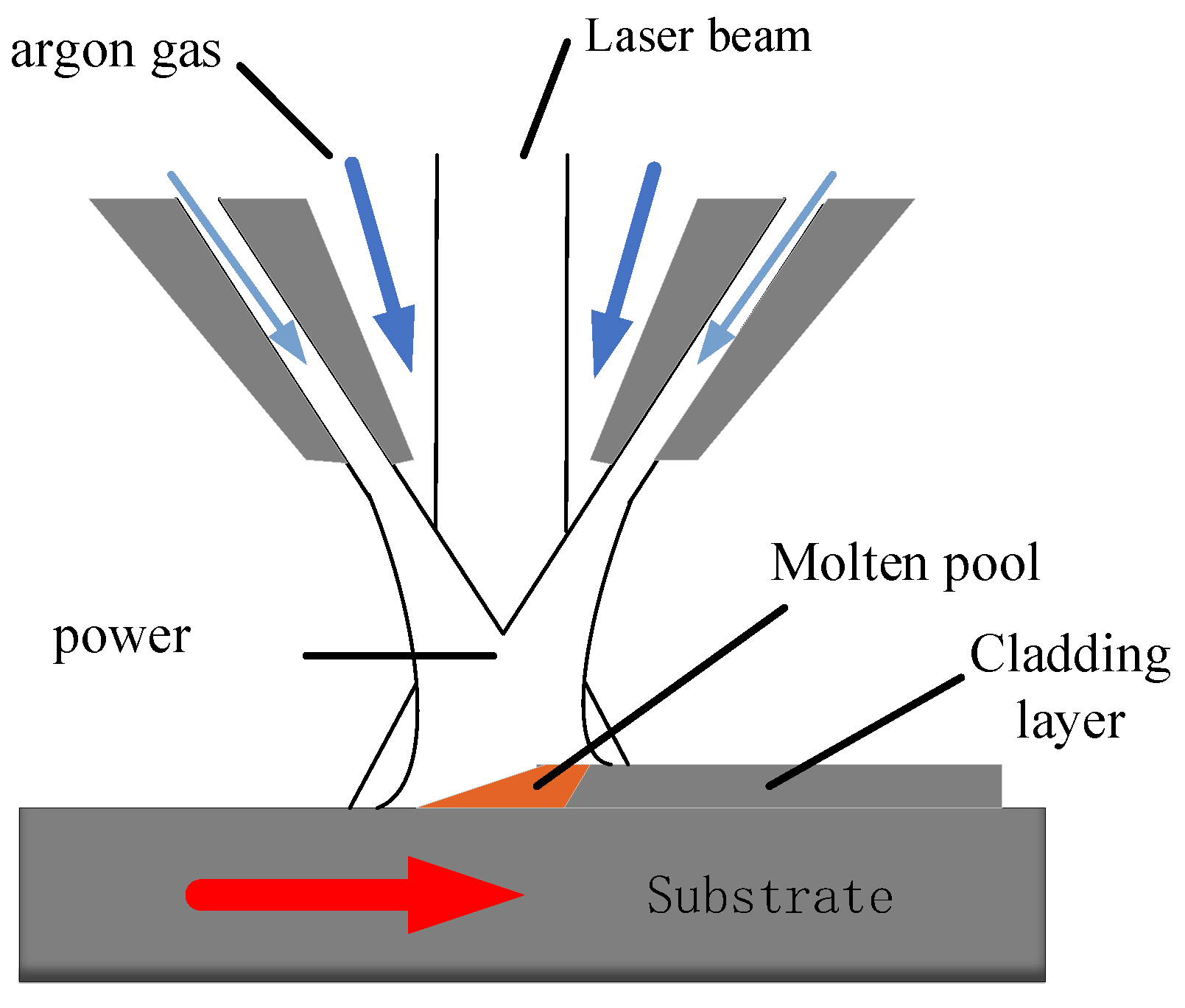
2.2. Experiment of Laser Cladding

Before the experiments, the surfaces of the Cu were polished using 300 grit silicon carbide (SiC) sandpaper to remove the oxide layers and contaminations. Next, the sample surfaces were cleaned with acetone and ethanol. An LDF-4000-40 semiconductor laser (Laserline, Koblenz, Germany) was selected in the experiment, as shown in Figure 1. Because the melting point of Mo is relatively high, in order to achieve full melting of Mo in the laser cladding process, combined with the previous parameter adjustment experiment, it was found that a 6000 W laser could melt the Mo. At the same time, Cu has a high thermal conductivity. When the laser power was too low or the speed was too fast, Mo could not be melted. When the speed was slow, the huge melting point difference between Mo and Cu would cause the Cu matrix to collapse. This, the laser cladding parameters were selected as follows: the laser power was 6000 W, the diameter of the laser beam spot was 2 mm, the laser scanning speed was 5 mm/s, and the powder feed rate was 10 g/min. Ni was introduced as the transition layer. When the number of transition layers was too small, the high temperature formed by the high melting point Mo on the transition layer would cause the Cu to collapse. When the transition layer was too thick, the hardness of the surface Mo layer would be reduced. Based on the compresive factors, three layers of the Ni layer and two layers of the Mo layer were prepared by laser.

2.3. Coating Characterization

The specimens were cut using a wire-cutting machine (ZhongXin, Taizhou, China) in a vertical position to the scanning direction. They were ground using #60 to #2000 metallographic SiC sandpapers and polished using a polish-grinding machine. The Ni-Cu layer and Mo-Ni-Cu mixed layer were etched with aqua regia for 10 s. The Mo layer was etched with etchants (HNO3: HCL: HF = 1:2:2). The time of corrosion was 5 s.
The microstructure evolution of the single trace coatings was characterized by optical microscopy (6XC, DiChengLianShuo, Tianjin, China) and scanning electron microscopy (Phenom g5 pure, Eindhoven, the Netherlands), as well as energy dispersive spectroscopy (EDS), with a working distance of 52.7μm, an accelerating voltage of 15 kV and a pressure of 0.1 Pa.
The composition of the cladding layer was identified by X-ray diffractometry (Rigaku D/max-2500/PC, Tokyo, Japan). XRD patterns were collected in the range of 10° ≤ 2θ ≤ 100° at a scanning velocity of 8°/min.
The room-temperature dry slide friction and wear experiments were performed in the M−2000 frictional wear tester (HengXu, Jinan, China), with the following conditions: the rotating speed was 300 r/min, the grinding time was 30 min, the glide distance was 84.78 m, the average load was 60 N. The diameter of the grinding ball was 3 mm, the material was 316 stainless steel, and the hardness was 290 HV. The dimension of the test specimens was 15 mm × 10 mm × 10 mm. Tests were completed three times per sample to measure the friction coefficient and wear rate.
The microhardness of the cross-sectional of the coatings was measured with an HVS-1000 Z microhardness analyzer (LiDun, Shanghai, China) at an applied load of 0.5 N and with a dwell time of 10 s. The hardness of the crosssection of the sample was tested three times from the coating surface to the substrate. The hardness test was carried out along the vertical direction at 250μm intervals, and a hardness test was carried out along the horizontal direction at 200μm intervals. The path of the hardness point is shown in Figure 2.

3. Results and Analysis

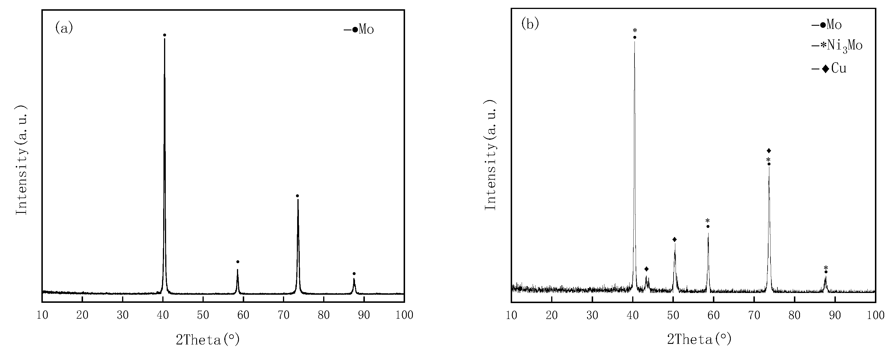
3.1. Analysis of Phase Compositions in Coatings

The XRD patterns of the coatings depicted in Figure 3a,b show the XRD of the cross-section of the cladding layer surface, the Mo-Ni-Cu mixed layer and the Mo layer, respectively, which are also described in Table 1. It can be observed from Figure 3a,b that the surface of the cladding layer was pure Mo and the cross-sections of the cladding layer were Mo, Ni3Mo and Cu, respectively [17]. The grain size was generally decreased by half of the value of the breadth of the diffraction peaks. Therefore, the average grain size of the coating was calculated with the Scherrer equation [18]. The average crystalline grain sizes of the Mo, Ni3Mo and Cu were 41.1, 28.8 and 17.3 nm, respectively. The lattice parameters of the Mo, Ni3Mo and Cu were 3.1469 Å, 2.3574 Å and 3.6262 Å, respectively. The Ni/Mo composite coating was prepared on the surface of the Cu alloy by laser. Firstly, Ni was cladded on the Cu matrix and then pure Mo was cladded by laser. Although the melting points of Mo and Ni are different, the XRD test on the surface showed that the surface of the coating could retain the characteristics of pure Mo if the parameters and the number of layers were properly controlled. According to the principle of heat transfer, the temperature is transferred from high to low. When the Mo layer was multi-layered and the surface was Mo, the melted Mo further melted the surface of the next layer through heat conduction. Because the laser cladding process is a comprehensive effect of laser energy absorption, heat is exchanged with the outside world and the energy loss occurs through heat conduction of the cladding layer to the substrate. When the laser energy was not enough, it only affected the surface layer of the previous layer, while the Mo and Ni mixed layer did not affect the composition of the surface layer. Ni3Mo was observed in the cross-section of the cladding layer. This was because that the Ni layer was first prepared, and then the Mo layer was prepared on the surface of the Ni layer in the process of laser preparation of the composite coating. The melting point difference between Ni and Mo was relatively large. In the Mo-Ni-Cu mixed layer, the combined action of molten high-temperature Mo liquid caused the uppermost Ni surface layer to melt, forming a eutectic area of Ni and Mo. Because of the good eutectic properties, the Ni and Mo formed hexagonal Ni3Mo, which can be inferred from point A in Table 1.

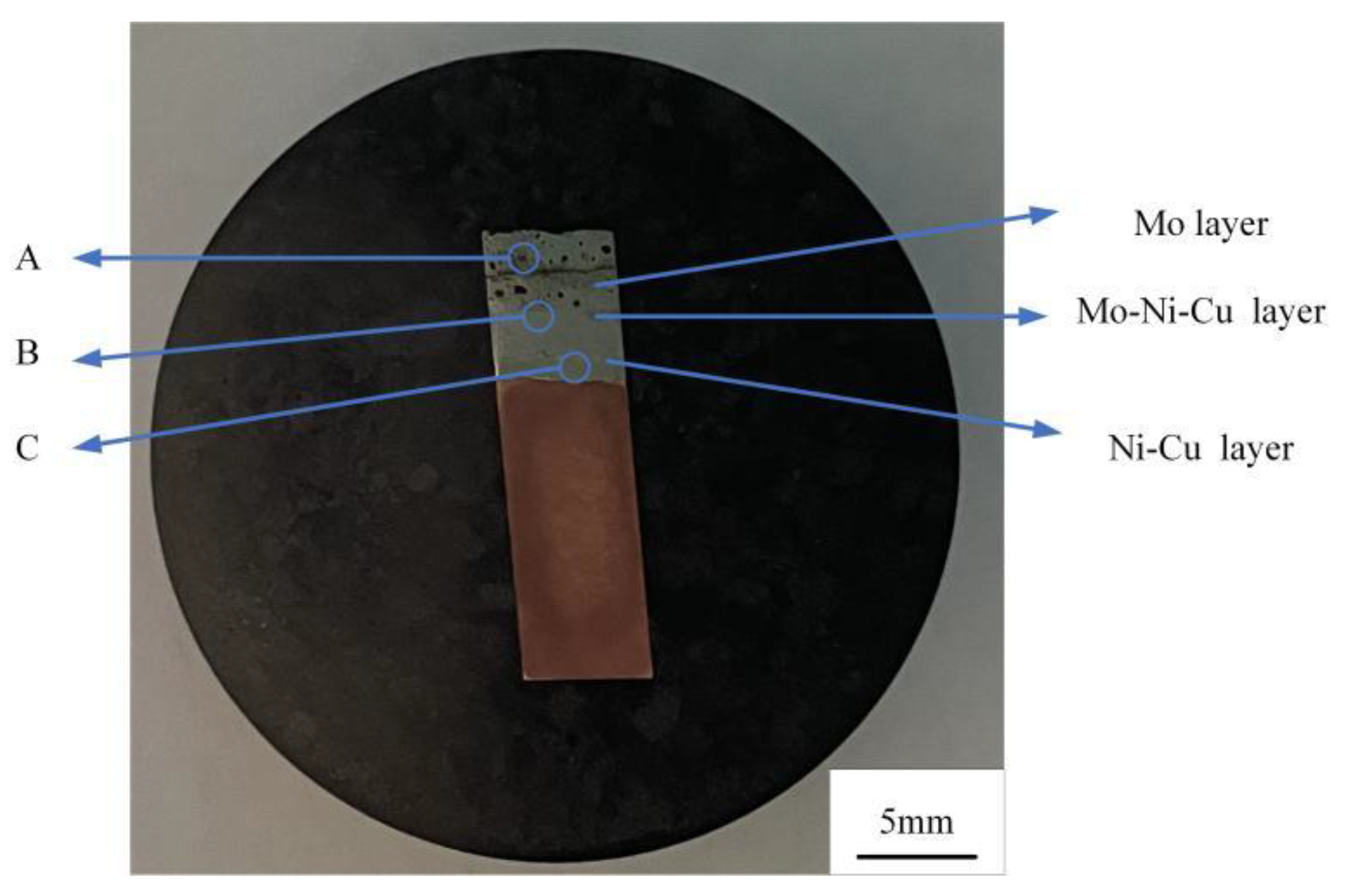
3.2. Macro Morphology of Composite Coating

It can be concluded from Figure 4 that the cross-section morphology of the cladding layer was a typical sandwich layer morphology containing the microstructure of Mo, the microstructure of the Mo-Ni-Cu mixed layer and the microstructure of the Ni-Cu mixed layer. This is supported by the information given in Table 1. However, dispersed pores and cracks were observed in the surface layer of the cladding layer. There were obvious unmelted regions in the interface of Mo and Mo. In the case of Ni powder on the Cu substrate, the resulting surface layer was a Ni-Cu solid solution because of the infinite mutual solubility and the small difference in melting points of Ni and Cu [17]. Because of the high thermal conductivity of Cu, the intermelting area of Cu and Ni was relatively small at the interface of Ni and Cu. Because the melting point of Mo was much higher than that of Ni, the high-temperature Mo molten pool could melt Ni through heat conduction, forming the eutectic region of Ni and Mo. A layer of Mo was cladded onto the Mo. Under the condition of insufficient energy of the laser, Mo that had melted at a high temperature could not melt the Mo surface through heat conduction due to comprehensive factors such as energy loss, and thus, unmelted regions were formed at the interface of Mo, and Mo was observed in the surface of the cladding layer. In the cross-section of the cladding layer, due to different elements in different regions, the sizes of the dendrites were different, and there were also differences in other comprehensive factors. As a result, the cross-section of the cladding layer had a sandwich-like appearance.
The pores were mainly concentrated in the Mo layer and Mo-Ni-Cu mixed layer. This was because Ni had good fluidity. Mo had a high adhesion coefficient at high temperatures, which reduced the fluidity of the molten pool. The escape velocity of the stomata was affected by the fluidity of the molten pool. Based on these comprehensive factors, pores were observed in Mo layer and the Mo-Ni-Cu mixed layer.

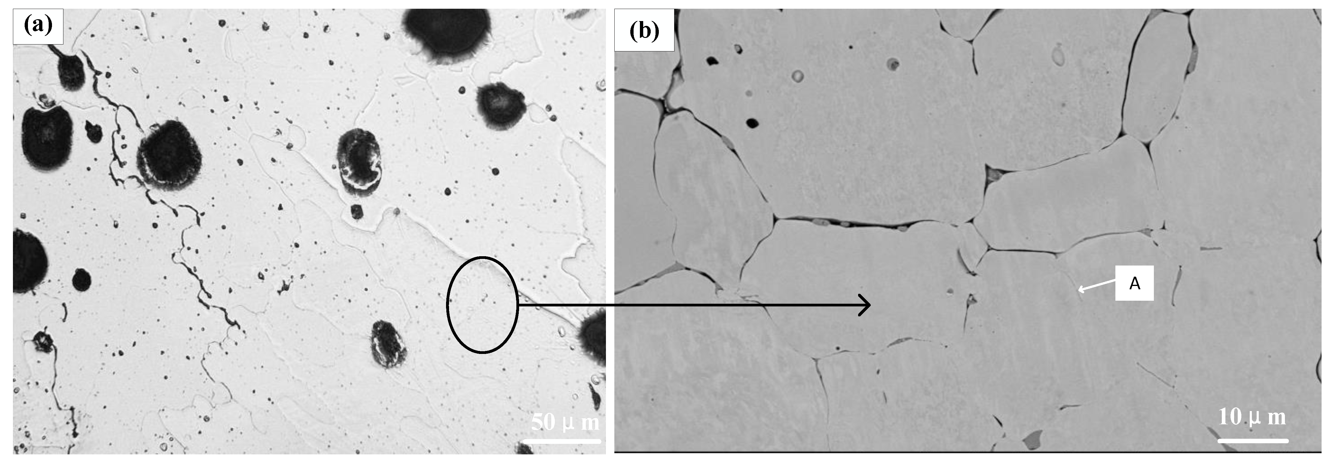
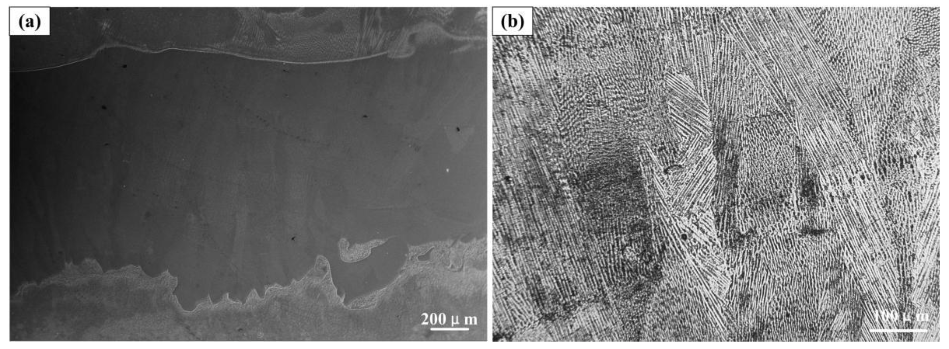
3.3. Microstructure of Laser Cladding Coating

It can be observed from Figure 5 that there were changes in the microstructure from the surface of the Mo layer to the Ni-Cu layer. It is illustrated in Figure 5a that there were pores and cracks in the Mo layer, and the cracks mainly propagated along the grain boundary. Cracks were formed at the grain boundary. This was because the laser cladding was of a non-equilibrium solidification type. The high melting point solidified first in the crystal nucleus, and finally solidified at the grain boundary. Due to the rapid heating and cooling of the laser, large thermal stress and residual stress occurred in the cladding layer. When the crystal nuclei were solidified, the liquid area on the grain boundary cracked under the action of stress, forming a crack [19]. Figure 5a is an enlargement of point A in Figure 4. Figure 5b is a larger version of Figure 5a, in which it can be observed that the microstructure of Mo in the surface layer was coarser than that in the lower layer. As clearly shown in Figure 5c, compared with the upper layer, the dendrites of the cladding layer tended to be refined near the Ni layer. Figure 5c is an enlargement of point B in Figure 2. The local enlargement of Figure 5c can be found in Figure 5d: the coarse microstructure of Mo layer was due to the formation of multi-layer scanning. The experiment of the next Mo layer was started without the previous Mo layer being completely cooled. The high-temperature region of the previous Mo layer, which was not completely cooled to room temperature, acted as an additional heat source, reducing the cooling rate of the next Mo layer and increasing the temperature of the molten pool.
It also can be concluded that from EDS results the Point A is mixture of Cu, Ni and Mo. Point B is Mo. The atomic ratio of Cu to Ni is approximately 1:5. This is due to the fast thermal conductivity of Cu and the melting point of Cu being far lower than that of Mo and Ni. When laser cladding the Ni and Mo layers, secondary remelting was caused to form a new molten pool. Cu entered the mixing layer and solidified to form the phenomenon of a Mo-Ni-Cu mixed layer; the closer this layer to the Cu matrix, the greater the Cu content. The crystal nuclei in the transition layer were composed of Mo, which was closely arranged. Additionally, the closer it was to the matrix, the smaller the dendrite was. The atomic ratio of Mo to Ni is approximately 1:3. XRD confirmed that Ni3Mo is formed by Ni and Mo. This is the case because Ni is a face-centered cubic structure and Mo is a body-centered cubic structure [20]. In the process of laser cladding, the temperature of the molten pool exceeded the melting point of Ni and Mo, which led to the unstable chemical properties of Mo and Ni, the breaking of the chemical bond, and the two recombining to form Ni3Mo. Ni was not found in the XRD observation. One possible reason is that during laser cladding, Ni entered the cladding layer due to dilution, but this Ni was formed Ni3Mo.
Figure 5e is an enlargement of point C in Figure 4. It shows the interface between the Mo-Ni-Cu mixed layer and Ni from Figure 5e. The surface area near Ni was dendritic. It was attributed to the area close to the Cu area, which had a high heat transfer. The organization is further enlarged in Figure 5e: it can be observed from Figure 5f that part of the dendritic structure appeared to be deflected. The dendrite growth transition was mainly caused by the deviation between the direction of dendrite growth and the direction of the local heat flux. The direction of dendrite growth is preferred along the opposite direction of heat flux [21]. With the laser scanning, the temperature of the molten pool increased gradually, and the dendrite grew along the opposite direction of heat transfer. During cooling, the dendrite deflected in a parallel direction to the heat flow and formed side branches. The solutes discharged from the side branches form secondary side branches in the cooling process, which prevented the normal growth of dendrites [22]. Finally, the structural morphology was formed, as shown in Figure 5f.
The interface structure of the Ni-Cu layer can be seen in Figure 6a. Because of the uneven heat transfer, the laser energy was close to the Gaussian distribution, and the interface between the Ni layer and the Cu matrix was characterized by irregular gears. A small amount of Cu floated up and was coated in the cladding layer. This was attributed to the fact that Cu is relatively light and the melting point of Cu is lower than that of Ni. When laser cladding Ni, Cu floated up and entered the molten pool. Thus, Cu was observed in the Ni layer after cooling.
It also can be concluded that the microstructure of the Ni layer was a fine dendritic structure and grew perpendicular to the interface. This was because the closer the microstructure was to the Ni layer, the closer it was to the Cu matrix. Due to the high thermal conductivity of Cu, according to the heat transfer, heat dissipation rate and thermal resistance, the closer the microstructure to the Cu area, the smaller the thermal resistance, and thus, the smaller the dendrite.

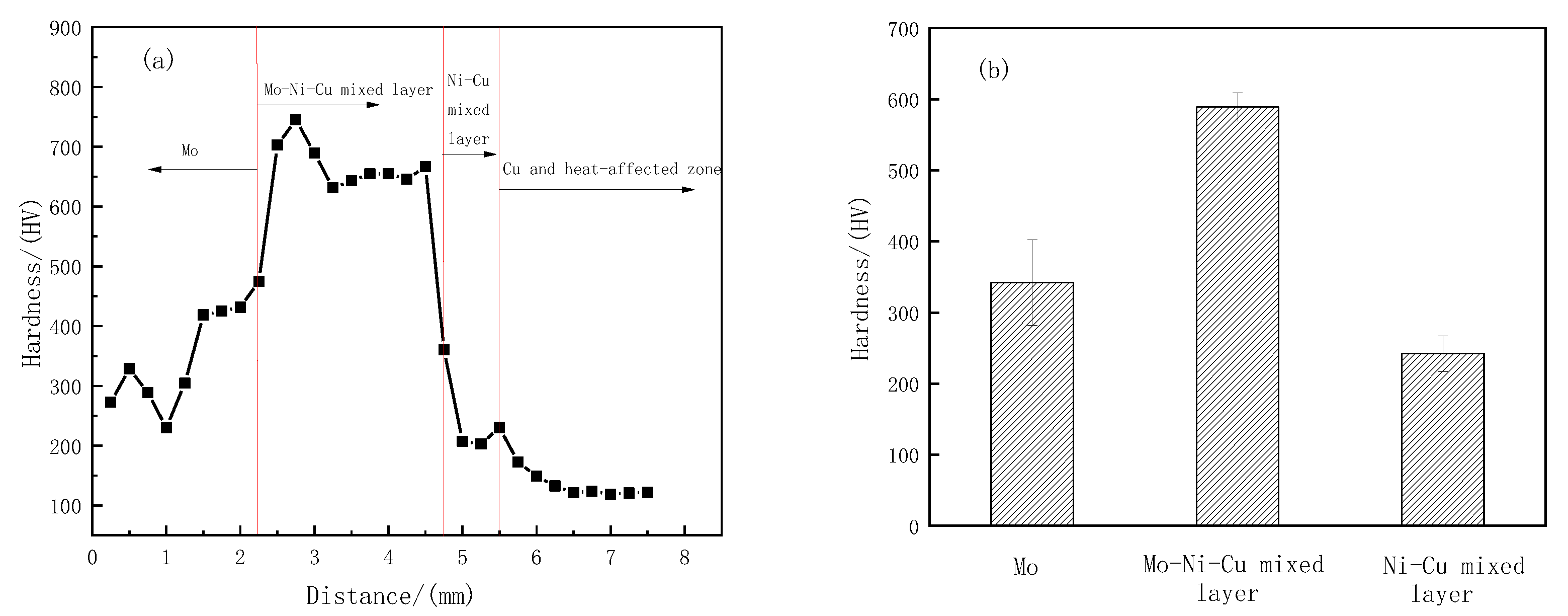
3.4. Microhardness of Laser Cladding Coatings

Figure 7 shows the hardness distribution from coating to substrate. It can be observed that the surface hardness of Mo layer was 200~460 HV. The average hardness of the Mo layer was 340 HV. The highest hardness was between 600 and 750 HV, which occurred in the clad layer of the Mo-Ni-Cu layer, which had an average hardness of 589 HV. The hardness in the Ni-Cu layer was 200~250 HV, and it had an average hardness of 242 HV. The average wear rate of the Mo layer was reduced by about three times in comparison with untreated Cu. The Mo layer grains could be refined under the action of laser cladding. A fine dendritic structure was formed, and thus, the hardness of the surface layer was improved. It can be observed from Figure 7 that the hardness of the Mo-Ni-Cu mixed layer was higher than that of the Mo layer, which was attributed to the fact that there was hard phase Ni3Mo and fine grain strengthening. The hardness decreased continuously as the depth increased. It can be seen from Figure 6b that in the Ni zone, the hardness of the pure Ni zone was lower than that of the mixed zone of Mo and Ni. This was because it was mostly composed of Ni and it had no hard strengthening phase. The hardness of the Cu matrix near the Ni layer was increased. This may be attributed to the recrystallization of the dendrite in the heat-affected zone caused by heat cycling and the grains becoming smaller. As we all know, small grains are beneficial in terms of improving the mechanical properties of materials according to the fine-grain strengthening effect [23]. Thus, the hardness in the heat-affected zone was higher than that of the Cu matrix.

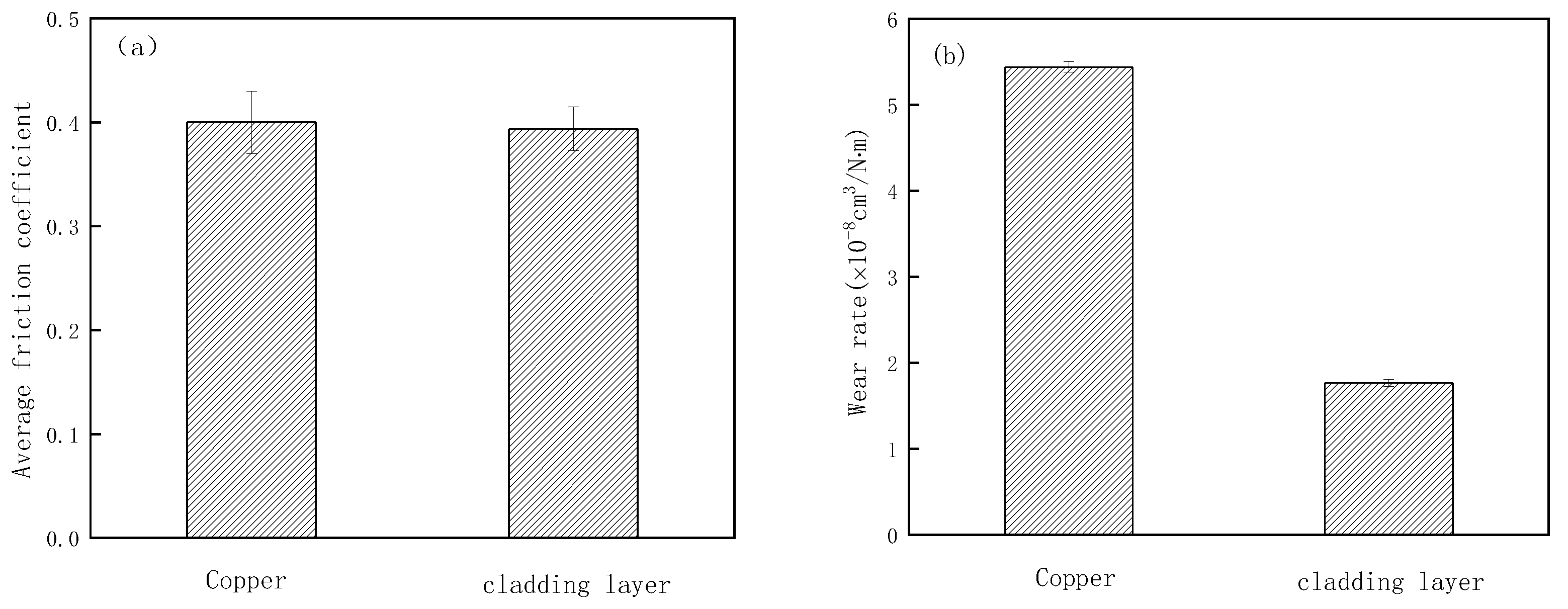
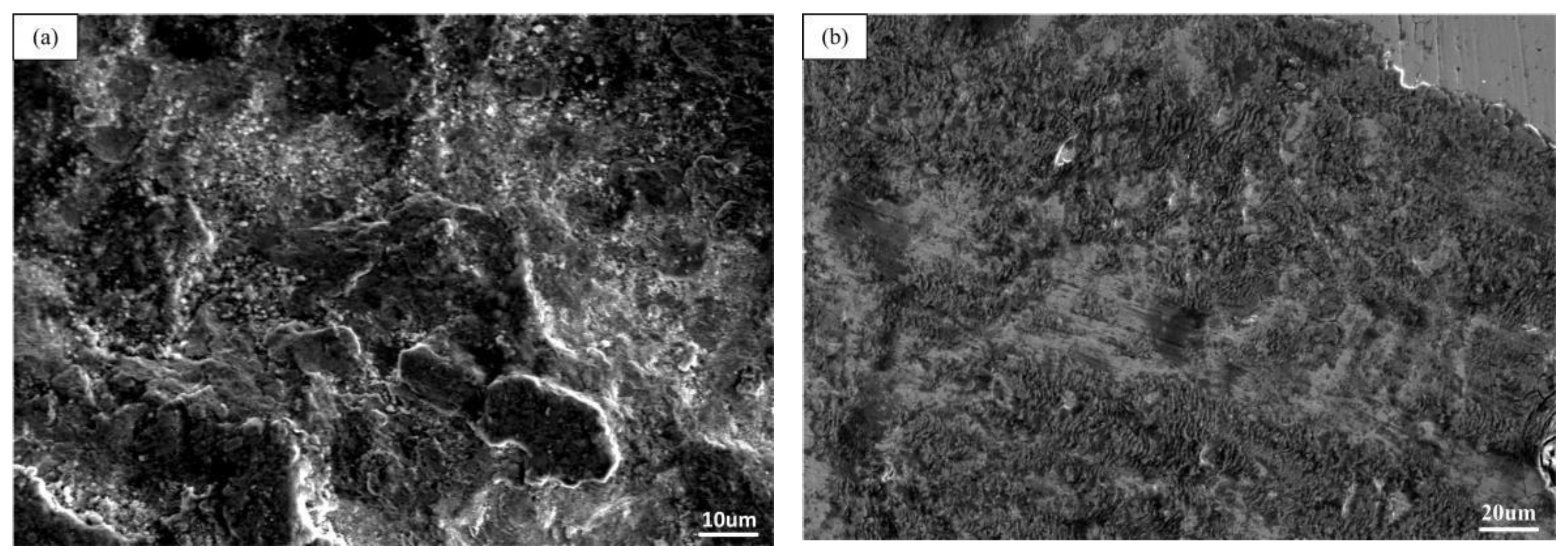
3.5. Wear Resistance of Laser Cladding Coating

Friction and sliding wear tests were carried out on the substrate and cladding layer using the wear testing machine. The wear rate of the matrix and cladding layer was calculated by using formula [24].
δ = Δ V F × S
Herein, δ was the wear rate (cm3/N·m), V was the wear volume (cm3), N was the normal load (N), and L represented the sliding distance (m).
Figure 8 shows the average friction coefficient and wear rates of the matrix and coating after the friction and wear experiment. Figure 8a shows that the friction coefficients (COF) at the stable stage were 0.37574 and 0.41262, respectively. It can be observed in Figure 8b that the wear rate of the matrix was three times that of the cladding layer. The matrix had higher wear rates and COF. However, the coatings had low wear rates. This indicated that the average friction coefficient and wear rates were reduced and that the cladding layer exhibited a lower wear rate. The low abrasion rate of Mo coating may be attributed to the high hardness. Under the condition of the same load, the wear resistance loss of the substrate was three times that of the surface layer. Figure 7 shows that the hardness of surface layer was three times that of the Cu substrate. Thus, the wear resistance of the structural coating was greatly enhanced.
Figure 9a shows the wear morphology of Cu, a large area of adhesion where pits appeared on the Cu surface, which was mainly adhesive wear [25]. In the relative motion of the steel ball, as Cu is a soft material, the “cold welding” effect caused the material on the Cu surface to be transferred. Subsequently, adhesion, shear and transfer occurred in the friction process [26], which damaged the Cu surface and produced wear debris. It can be observed from Figure 9a that the material was seriously damaged and a large area of plastic deformation occurred at the wear location, resulting in plastic damage and a large scratch area.
Figure 9b shows the wear morphology of the cladding layer. Furrows, pits and flaky wear debris appeared on the ground surface. The main wear mechanism of the Mo was abrasive wear, as the Mo particles yield abrasive wear when they were pulled out from the coating, so it was difficult to produce a plastic deformation during dry sliding wear [27,28]. When the sample and the friction pair were in relative motion, furrow-like scratches would be generated and a certain wear track would be formed. During the friction between Mo and the steel ball, the heat was generated, which led to the oxidation and volatilization of the Mo surface. At the same time, under the action of various forces, the deformation of the worn surface was aggravated, and the flake was formed, which caused abrasive wear to appear on the surface.

3.6. Improvements

The residual stress generated after the cladding layer was caused by the physical properties of the substrate and the cladding layer. Therefore, the thermal stress could be reduced by reducing the difference in the thermal expansion coefficient between the cladding layer and the substrate. The toughness of the cladding layer could be increased so that it does not easily to crack under the action of stress. Because rare earth elements have the capacity to reduce defects and increase the hardness of the cladding layer. Metal oxides could stir the molten pool under convective impact, which would be beneficial in terms of gas discharge and improve the fluidity of the molten pool. At the same time, the addition of metal oxides is equivalent to the addition of many non-spontaneous crystal nuclei in the molten pool, which would increase the nucleation rate and the crystal grain size [29]. The rare earth oxide CeO2 could increase the absorption rate of laser radiation energy [30] so that more Mo will be melted into the molten pool. In this way, it will be possible to reduce the thermal expansion difference between the Mo and the Ni layer and reduce the cracking tendency of the Mo layer.

4. Results and Discussion

Laser cladding of Mo/Ni on Cu substrate was attempted with the aim of enhancing wear resistance. The following concluding remarks are drawn.
(1)
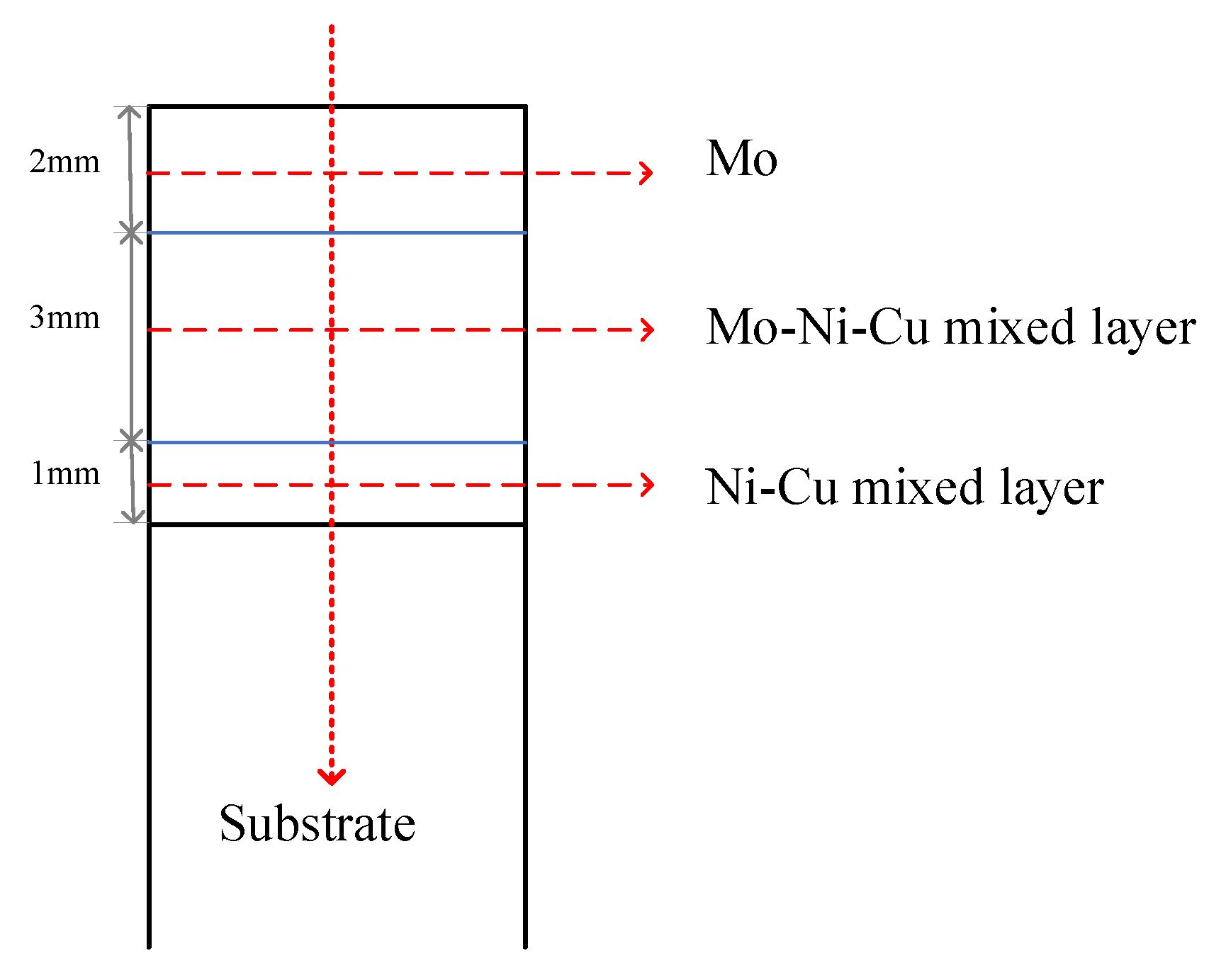
By using a laser power of 6000 W, a scanning speed of 5 mm/s and a feed rate of 10 g/min, three Ni layers and two Mo layers were cladded. By these means, cladding layers with pure Mo on the surface could be prepared.
(2)
Due to the comprehensive factors such as poor fluidity of the molten pool of Mo and non-equilibrium solidification of the laser, pores and cracks were easily formed in the pure Mo layer.
(3)
In order to prepare wear-resistant and high-thermal-conductivity coating on the Cu, Ni was introduced to overcome the incompatibility of Cu and Mo. It was found that the surface hardness of the cladding layer could be increased by three times relative to that of the substrate. The volumetric wear rate of Cu was three times that of the cladding layer. The main wear mechanism of the Mo was abrasive wear, and that of the Cu was adhesive wear.

Author Contributions

Conceptualization and Methodology, M.P.; Investigation and Validation, M.S. All authors have read and agreed to the published version of the manuscript.

Funding

This work was financially supported by the National Natural Science Foundation of China (Grant No. 52075559).

Institutional Review Board Statement

Not applicable.

Informed Consent Statement

Not applicable.

Data Availability Statement

Not applicable.

Conflicts of Interest

The authors declare no conflict of interest.

References

  1. Ma, W.-Z.; Lu, J.-Y. Thinking and study of electromagnetic launch technology. J. IEEE Trans. Plasma Sci. 2017, 45, 1071e7. [Google Scholar] [CrossRef]
  2. Xie, H.-B.; Yang, H.-Y.; Yu, J.; Gao, M.-Y.; Shou, J.-D.; Fang, Y.-T.; Liu, J.-B.; Wang, H.-T. Research progress on advanced rail materials for electromagnetic railgun technology. J. Def. Technol. 2021, 17, 429–439. [Google Scholar] [CrossRef]
  3. Ren, F.-Z.; Yin, L.-T.; Wang, S.-S.; Volinsky, A.A.; Tian, B.-H. Cyanide-free silver electroplating process in thiosulfate bath and microstructure analysis of Ag coatings. J. Trans. Nonferrous Met. Soc. China 2013, 23, 3822e8. [Google Scholar] [CrossRef]
  4. Zhou, Z.-Y.; Liu, X.-B.; Zhuang, S.-G. Preparation and high temperature tribological properties of laser in-situ synthesized self-lubricating composite coatings containing metal sulfides on Ti6Al4V alloy. J. Appl. Surf. Sci. 2019, 481, 209–218. [Google Scholar] [CrossRef]
  5. Liu, X.-B.; Meng, X.-J.; Liu, H.-Q. Development and characterization of laser clad high temperature self-lubricating wear resistant composite coatings on Ti-6Al-4V alloy. J. Mater. Des. 2014, 55, 404–409. [Google Scholar] [CrossRef]
  6. Yang, M.-S.; Liu, X.-B.; Fan, J.-W. Microstructure and wear behaviors of laser clad Ni/Cr3C2-WS2 high temperature self-lubricant wear-resistant composite coating. J. Appl. Surf. Sci. 2012, 258, 3757–3762. [Google Scholar] [CrossRef]
  7. Liu, G.-M.; Li, J.; Zhang, Q.-X.; Li, B. Failure mechanism of railways for H62 brass electromagnetic gun. J. Acad. Armored Force Eng. 2013, 27, 90–94. [Google Scholar]
  8. Dong, J.; Liu, F.; Chen, S.-Y. Preparation of Co-Ni-Cu gradient coatings by CO2 laser cladding on Cu plate. J. Northeast. Univ. 2008, 29, 1581–1584. [Google Scholar]
  9. Gu, Y.; Zhao, P.-X. Performance of novel metal/ceramic coating on the surface of Cu alloy. J. Mater. Prot. 2017, 50, 22–26. [Google Scholar] [CrossRef]
  10. Yang, Q.-Q.; Xu, Y.; Zhao, M.-L.; Wang, B.; Shao, X.-H.; Li, Y.-F. Effect of adding trace Cr Al Sn and Ni on the properties of Cu alloy. J. Spec. Cast. Non-Ferr. Alloy. 2020, 40, 690–693. [Google Scholar] [CrossRef]
  11. Dehm, G.; Medres, B.; Shepeleva, L.; Bamberger, M.; Mordike, B.L.; Mordike, S.; Ryk, G.; Halperin, G.; Etsion, I. Microstructure and tribological properties of Ni-based claddings on Cu substrates. J. Wear 1999, 225–229, 18–26. [Google Scholar] [CrossRef]
  12. Leech, P.W. Laser surface melting of a complex high alloy steel. J. Mater. Des. 2014, 54, 539–543. [Google Scholar] [CrossRef]
  13. Wirth, F.; Wegener, K. A physical modeling and predictive simulation of the laser cladding process. J. Addit. Manuf. 2018, 22, 307–319. [Google Scholar] [CrossRef]
  14. Smelov, V.G.; Sotov, A.V.; Murzin, S.P. Particularly Selective Sintering of Metal Powders by Pulsed Laser Radiation. In Key Engineering Materials; Trans Tech Publications Ltd.: Freienbach, Switzerland, 2016; Volume 685, pp. 403–407. [Google Scholar] [CrossRef]
  15. Xue, K.-N.; Lu, H.-F.; Luo, K.-Y.; Cui, C.-Y.; Yao, J.-H.; Xing, F.; Lu, J.-Z. Effects of Ni25 transitional layer on microstructural evolution and wear property of laser clad composite coating on H13 tool steel. J. Surf. Coat. Technol. 2020, 402, 126488. [Google Scholar] [CrossRef]
  16. Okamoto, H.; Massalski, T.B. Binary alloy phase diagrams requiring further studies. J. Phase Equilibria 1994, 15, 500–521. [Google Scholar] [CrossRef]
  17. Ng, K.W.; Man, H.C.; Cheng, F.T.; Yue, T.M. Laser cladding of Cu with Mo for wear resistance enhancement in electrical contacts. J. Appl. Surf. Sci. 2007, 253, 6236–6341. [Google Scholar] [CrossRef]
  18. Chun, S.-Y. Changes of Crystal Structure and Microstructure of MoN Coatings in Accordance with Inductively Coupled Plasma Power. J. Coat. 2021, 11, 1351. [Google Scholar] [CrossRef]
  19. Zimmermann, G.; Pickmann, C.; Schaberger-Zimmermann, E.; Galindo, V.; Eckert, K.; Eckert, S. Do rotating magnetic fields unconditionally lead to grain refinement? A case study for directionally solidified Al-10wt%Cu alloys. J. Mater. 2018, 3, 326–337. [Google Scholar] [CrossRef]
  20. Li, X.-Z. Ni-Cr-Mo and Ni-Mo Preparation and Properties of Cladding Layer. Master’s Thesis, North China Electric Power University, Beijing, China, 2014. [Google Scholar]
  21. Zhang, Q. Study on Dendrite Turning Growth Behavior and Element Segregation Inhibition of IN718 Alloy by Laser Cladding. Master’s Thesis, Zhejiang University of Technology, HangZhou, China, 2020. [Google Scholar] [CrossRef]
  22. Huang, S.-Y.; Shangguan, X.-F.; Chen, J.; Zhang, Y.-Q.; Liu, Y.-Y. Dendrite splitting and orientation Deflection during directionally solidified Mo0.2FeCoCrNi high entropy alloy. J. Xi Univ. Technol. 2019, 39, 65–71. [Google Scholar] [CrossRef]
  23. Feng, Y.; Du, Z.; Hu, Z. Effect of Ni Addition on the Corrosion Resistance of NiTi Alloy Coatings on AISI 316L Substrate Prepared by Laser Cladding. J. Coat. 2021, 11, 1139. [Google Scholar] [CrossRef]
  24. Zhang, H.; Zhang, C.-H.; Wang, Q.; Wu, C.-L.; Zhang, S.; Chen, J.A.O. Abdullah. Effect of Ni content on stainless steel fabricated by laser melting deposition. J. Opt. Laser Technol. 2018, 101, 363–371. [Google Scholar] [CrossRef]
  25. Cai, B.; Tan, Y.-F.; Tu, Y.-Q. Tribological properties of Ni-base alloy composite coating modified by both graphite and TiC particles. J. Trans. Nonferr. Met. Soc. China 2011, 21, 2426–2432. [Google Scholar] [CrossRef]
  26. Yan, H. Study on Laser Composite Wear Resistant Layer and Interface Characteristics of Cu Alloy. Ph.D. Thesis, Huazhong University of Science and Technology, Wuhan, China, 2010. [Google Scholar]
  27. Xiang, Z.-F.; Liu, X.-B.; Ren, J. Investigation of laser cladding high temperature anti-wear composite coatings on Ti6Al4V alloy with the addition of self-lubricant CaF2. J. Appl. Surf. Sci. 2014, 313, 243–250. [Google Scholar] [CrossRef]
  28. Yan, Z.; Jiang, D.; Gao, X. Friction and wear behavior of tin films against ceramic and steel balls. J. Tribol. Int. 2018, 124, 61–69. [Google Scholar] [CrossRef]
  29. Wang, C.-L.; Gao, Y.; Wang, R.; Wei, D.-Q.; Cai, X.; Fu, Y.-K. Microstructure of laser-clad Ni60 cladding layers added with different amounts of rare-earth oxides on 6063 Al alloys. J. Alloys Compd. 2018, 740, 1099–1107. [Google Scholar] [CrossRef]
  30. Liu, Y.-N.; Sun, R.-L.; Niu, W.; Zhang, T.-G.; Lei, Y.-W. Effects of CeO2 on microstructure and properties of TiC/Ti 2 Ni reinforced Ti-based laser cladding composite coatings. J. Opt. Lasers Eng. 2019, 120, 84–94. [Google Scholar] [CrossRef]
Figure 1. Schematic diagram of synchronous powder feed.
Coatings 11 01460 g001
Figure 2. Schematic diagram of hardness measurement path.
Coatings 11 01460 g002
Figure 3. X-ray diffraction pattern of laser: (a) X-ray diffraction pattern of surface laser; (b) X-ray diffraction pattern of the cross-section laser.
Coatings 11 01460 g003
Figure 4. Macro Morphology.
Coatings 11 01460 g004
Figure 5. Microstructure from Mo to Ni-Cu layer: (a) microstructure of the Mo layer; (b) enlarged view of the microstructure of the Mo layer; (c) microstructure of the middle part of the Mo-Ni-Cu mixed layer; (d) enlarged view of the microstructure of the middle part of the Mo-Ni-Cu mixed layer; (e) microstructure of the bottom of the Mo-Ni-Cu mixed layer; (f) enlarged view of the microstructure of the bottom of the Mo-Ni-Cu mixed layer.
Coatings 11 01460 g005aCoatings 11 01460 g005b
Figure 6. Microstructure diagram from Ni layer to Cu matrix: (a) microstructure of Ni-Cu layer; (b) enlarged view of Microstructure of Ni-Cu layer.
Coatings 11 01460 g006
Figure 7. The hardness of the cladding layer: (a) the hardness distribution from the surface of the laser cladding to the substrate; (b) the average hardness of each layer.
Coatings 11 01460 g007
Figure 8. The average friction coefficient (a) and the average wear rates (b) of the coatings and the matrix.
Coatings 11 01460 g008
Figure 9. Wear morphology of Cu substrate and laser cladding: (a) wear morphology of the Cu substrate; (b) wear morphology of the cladding layer.
Coatings 11 01460 g009
Table 1. Point energy spectrum analysis results for different areas of the cladding layer (at.%).
Test AreaCuNiMo
A--100.00
B-3.8696.14
C10.0154.3918.66
D--100.00
Publisher’s Note: MDPI stays neutral with regard to jurisdictional claims in published maps and institutional affiliations.

