Article

Fracture Properties of α– and ĸ–Al2O3 Hard Coatings Deposited by Chemical Vapor Deposition

1
Christian Doppler Laboratory for Advanced Coated Cutting Tools, Department of Materials Science, Montanuniversität Leoben, 8700 Leoben, Austria
2
Department of Materials Science, Montanuniversität Leoben, 8700 Leoben, Austria
3
Ceratizit Austria GmbH, 6600 Reutte, Austria
*
Author to whom correspondence should be addressed.
Coatings 2021, 11(11), 1359; https://doi.org/10.3390/coatings11111359
Submission received: 15 September 2021 / Revised: 28 October 2021 / Accepted: 1 November 2021 / Published: 4 November 2021
(This article belongs to the Special Issue Chemical Vapor Deposition (CVD) Coatings)

Abstract

:
Although α– and κ–Al2O3 hard coatings deposited by chemical vapor deposition are well established in the metal-cutting industry for their ability to increase the performance and lifetime of cutting tools, the literature on their fracture properties is scarce. Thus, within this study, the microstructure and mechanical properties of α– and κ–Al2O3 coatings were investigated and compared to each other. X-ray diffraction and scanning electron microscopy combined with electron backscatter diffraction showed that both coatings exhibited a fiber texture, where the α–Al2O3 coating displayed a (0001) texture and the κ–Al2O3 coating a (001) texture with a certain (013) contribution. Higher hardness and Young’s modulus values of 31.0 ± 0.9 GPa and 474.6 ± 12.5 GPa, respectively, were obtained for the α–Al2O3 coating, compared to 24.2 ± 0.8 GPa and 356.8 ± 7.9 GPa for κ–Al2O3. While the α–Al2O3 coating exhibited a higher fracture stress of 8.1 ± 0.3 GPa (compared to 6.4 ± 0.6 GPa for κ–Al2O3), the κ–Al2O3 coating showed a higher fracture toughness of 4.4 ± 0.3 MPa*m1/2 (compared to 3.2 ± 0.3 MPa*m1/2 for alpha).

1. Introduction

Wear-resistant coatings deposited by chemical or physical vapor deposition (CVD, PVD) are commonly used in the metal-cutting industry to increase the performance and lifetime of cemented carbide cutting inserts [1]. Due to the unique combination of chemical inertness and high hot hardness, Al2O3 deposited by thermally activated CVD is predestined for the turning of steel and cast iron, where high temperatures emerge at the cutting edge [2,3,4]. Al2O3 has many different crystallographic polymorphs such as α, γ, δ, η, θ, κ and χ, where only α–, κ– and γ–Al2O3 can be deposited by CVD in a controlled way [5,6,7,8]. The thermodynamically stable α-Al2O3 and the metastable κ–Al2O3 are used as wear-resistant coatings in order to increase the performance of cutting tools [9,10]. A trigonal (space group R-3c) structure characterizes the α–Al2O3, whereas the κ–Al2O3 exhibits an orthorhombic (space group Pna2I) structure. The former has an ABAB and the latter an ABAC stacking of almost close-packed oxygen ion planes [6]. The unit cell of α–Al2O3 consists of six layers of oxygen anions and six layers of aluminum cations. α–Al2O3 is described by the hexagonal cell, where the oxygen anions are packed in a hexagonal close-packed (hcp) arrangement with aluminum cations in two thirds of the octahedral sites. The unit cell of κ–Al2O3 is composed of four layers of oxygen anions with aluminum cations occupying one third of both the tetrahedral and octahedral positions [6].
Compared to the thermodynamically stable α–Al2O3, the metastable κ–Al2O3 has a significantly lower thermal conductivity; thus, κ–Al2O3 coatings are more effective thermal barriers than α–Al2O3 coatings [6]. However, the main disadvantage of the metastable κ–Al2O3 is the phase transformation to the thermodynamically stable α–Al2O3 at elevated temperatures (≥1000 °C). This κ→α phase transformation can be induced during metal cutting due to high temperatures arising during application. The phase transformation is accompanied by a volume contraction of approximately 7%. Thus, secondary cracks evolve in addition to the primary thermal crack network typically observed in CVD hard coatings due to the different thermal expansion coefficients of the coating and substrate material and therefore deteriorate the coating performance [6,11,12,13]. Consequently, in applications where temperatures of ≥1000 °C are reached, α–Al2O3 is used [14]. Recent findings regarding nucleation behavior and advances in deposition technology allow us to control the growth of textured α–Al2O3 coatings through optimizing the underlying bonding layer [14]. Ruppi et al. have shown that α–Al2O3 coatings with a (0001) texture have the most beneficial properties for the turning of steel compared to other textures and α–Al2O3 obtained through the κ→α phase transformation [15]. The superior performance of (0001) textured α–Al2O3 can be explained by the activation of the basal slip system, which has a three-fold symmetry, ensuring a more uniform plastic deformation compared to other textures; thus, the tool surface is protected more efficiently [15].
While microstructure, hardness, Young´s modulus and coating performance of both CVD α– and κ–Al2O3 have been investigated in detail, no literature is available concerning a fundamental comparison regarding the micromechanical properties such as fracture stress and fracture toughness. Thus, within this study, α–Al2O3 and κ–Al2O3 coatings were synthesized on cemented carbide substrates using thermally activated CVD. The microstructure of the coatings was studied by scanning electron microscopy (SEM). X-ray diffraction (XRD) was used for qualitative phase analysis. Information on the texture of the coatings was obtained using electron back-scatter diffraction (EBSD). Furthermore, nanoindentation was applied to determine differences in hardness and Young’s modulus between the coatings. Finally, the main focus of the investigation was laid on micro-cantilever bending tests, which provided information about the fracture properties of the coatings.

2. Materials and Methods

The α– and κ–Al2O3 coatings investigated in this study were deposited by thermal CVD using a SuCoTec SCT6000TH (Sucotec, Langenthal, Switzerland) deposition system. The Al2O3 coatings were synthesized as top layers on a TiCN intermediate layer and a TiN diffusion barrier on cemented carbide substrates. The elemental composition of the cemented carbide substrates was 88 wt.% WC, 6 wt.% Co and 6 wt.% mixed carbides for the α– and 77 wt.% WC, 11 wt.% Co and 12 wt.% mixed carbides for the κ–Al2O3 coating system. The α– and κ–Al2O3 top layers, with a thickness of ~9 µm and ~11 µm, respectively, were deposited using AlCl3-CO2-H2-H2S precursors at a temperature of 1000 °C and a pressure of 75 mbar [9,16].
In order to investigate the microstructure of the coatings, a Bruker D8 Advance X-ray diffractometer (Bruker AXS, Karlsruhe, Germany) in locked–coupled mode and parallel-beam configuration was applied. To obtain additional information about the texture of the coatings, a FEI Versa 3D DualBeam workstation (Thermo Fisher Scientific, Waltham, MA, USA) equipped with an EDAX Hikari XP EBSD camera (EDAX Inc., Mahwah, NJ, USA) in combination with the TSL OIM analysis 8.5 software package from EDAX Inc. was used. Prior to the measurements, the coatings were mechanically polished by using a 3 µm and a 1 µm diamond paste. After the measurements, the EBSD pattern was post-processed using neighbor pattern averaging and re-indexing (NPAR) provided by the above-mentioned software package. The evaluation of the acquired inverse pole figure (IPF) EBSD surface maps allowed the identification of the grain size distribution and the qualitative description of the grain shape. Furthermore, EBSD pole figures determined from the orientation information of the EBSD scans were used also to study the texture on a macroscopic scale.
To investigate the hardness and Young’s modulus of the coatings, nanoindentation measurements on mirror-polished surfaces of the samples were performed using a G200 nanoindenter (KLA, Milpitas, CA, USA), equipped with a diamond Berkovich tip (Synton-MDP, Nidau, Switzerland). On both coatings, 16 indents in a load-controlled mode with a maximum load of 15 mN, resulting in penetration depths less than 10% of the coating thickness, were applied. The evaluation of the load–displacement curves was carried out according to the method of Oliver and Pharr [17] using a Poisson ratio of 0.24 for both polymorphs. The Poisson ratio of both polymorphs was calculated from single crystal elastic constants using the software package DECcalc [18,19,20]. Unnotched and notched micro-cantilevers were fabricated using the above-mentioned FIB/SEM workstation to target dimensions of ~19 µm in length and a square cross-section of ~3 × 3 µm2. The micro-cantilevers were milled with a Ga+ ion beam (30 keV, 10 nA), followed by fine milling (30 keV, 1 nA). Micro-cantilevers used for fracture toughness evaluation were notched, using an even lower milling current (30 keV, 10 pa), at a distance ~1 μm away from the microcantilevers support. Additionally, information about the crystallographic orientation of the micro-cantilevers was verified using the above-described EBSD equipment. The micro-cantilevers were tested using a Hysitron TI 950 TriboIndenter (Bruker, Billerica, MA, USA), equipped with a conospherical diamond tip (Synton-MDP, Nidau, Switzerland). The micro-cantilevers were loaded ~1 µm from the free end of the beam with a displacement rate of 50 nm/s until fracture occurred. In order to gain reliable fracture stress and fracture toughness values for both coating systems, a minimum of three notched and unnotched beams were tested and evaluated. Fracture stress σF was determined using following formula:
σ F = 6 F l B w 2     ,
where F is the maximum load at which fracture occurs and l is the bending length from the micro-cantilever support to the position of the indenter tip. B is the micro-cantilever width and w indicates the micro-cantilever thickness. According to Matoy et al. [21], the fracture toughness KIC was calculated from notched micro-cantilevers as described in the formula below:
K I C = σ F π a   f ( a w )     ,
where f ( a w )   is the dimensionless shape factor and can be calculated by using the following formula [21]:
f ( a w ) = 1.46 + 24.36 ( a w ) 47.21 ( a w ) 2 + 75.18 ( a w ) 3 ,  
where a is the notch-depth and w denotes the thickness of the micro-cantilever.
After the micro-cantilever bending tests, the fracture surfaces and the depths of the notches were examined by the same FIB/SEM as mentioned above. In addition, the Young´s moduli were determined from the load-displacement curves of the unnotched micro-cantilevers by using the Euler-Bernoulli beam theory [22] and then were compared with the Young’s moduli determined by nanoindentation.

3. Results and Discussion
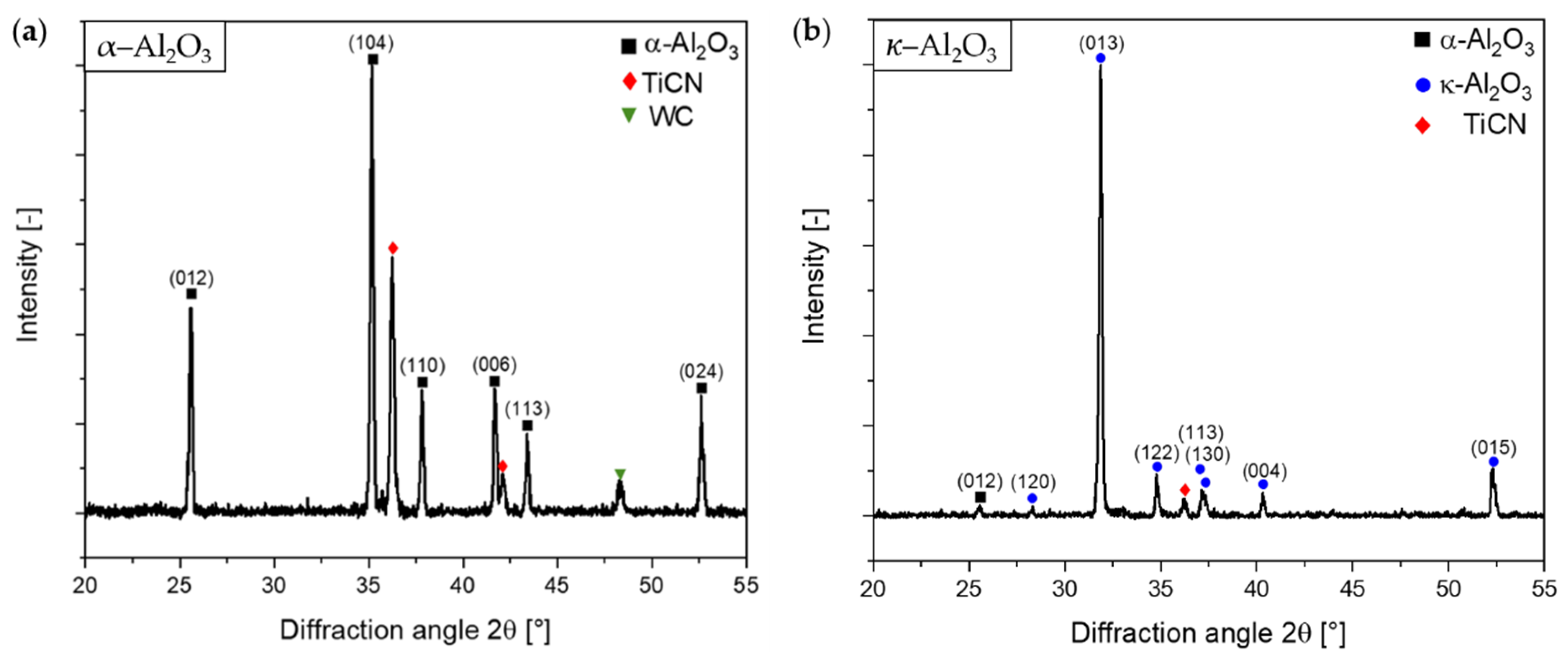
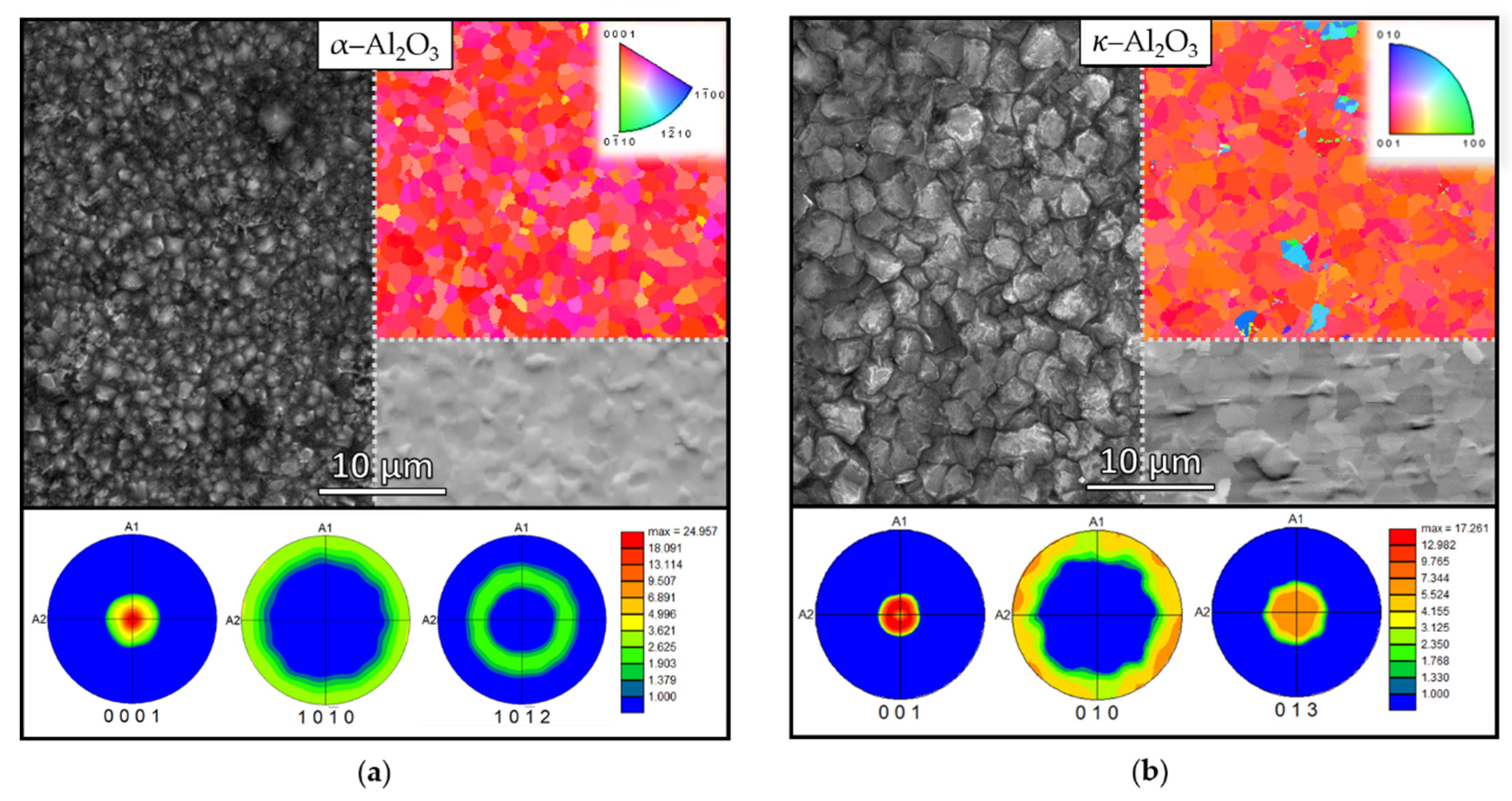
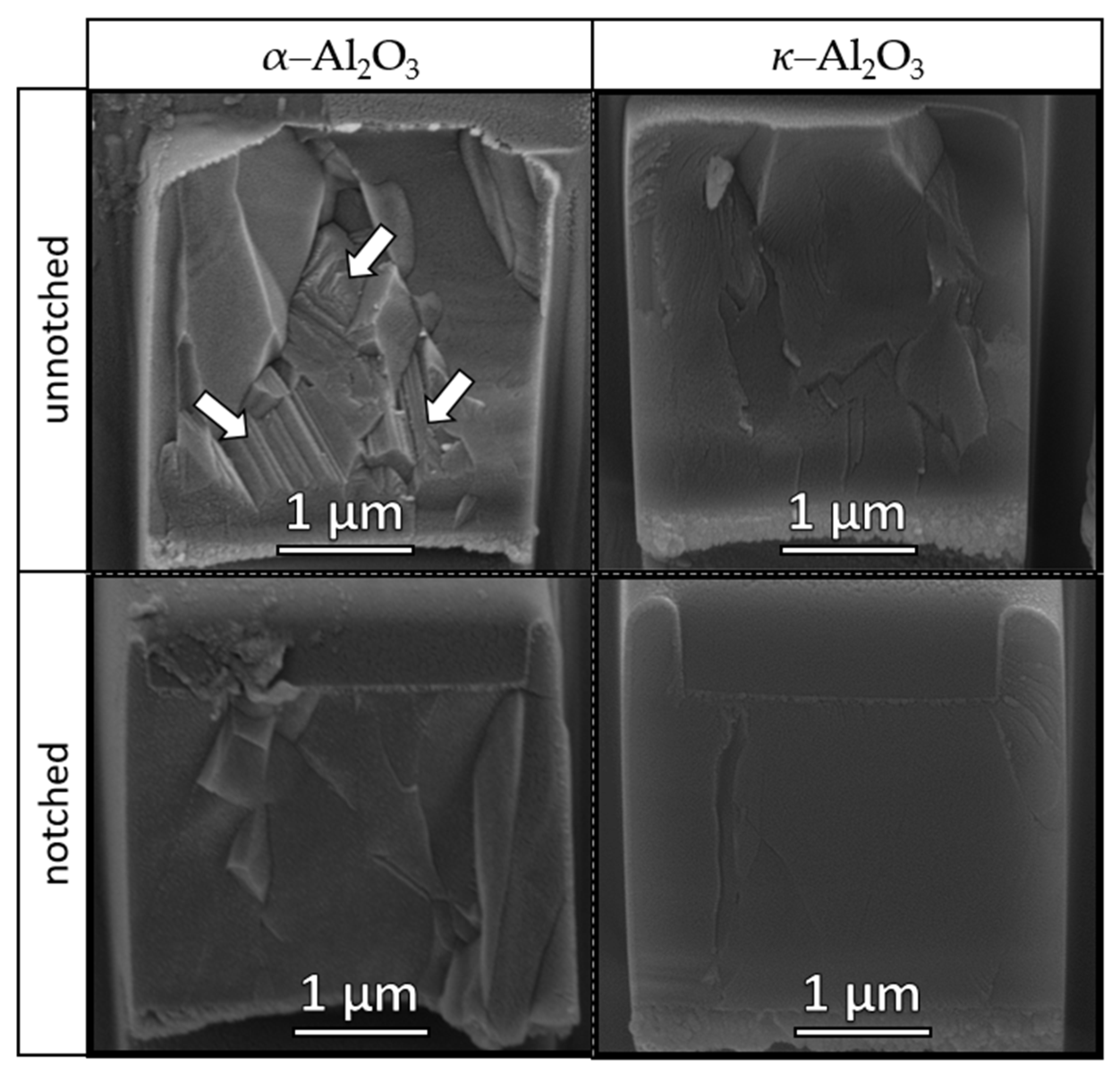
3.1. Microstructure

X-ray diffractograms of α– and κ–Al2O3 are shown in Figure 1a,b, respectively. Peak positions according to diffraction standards of α–Al2O3 (00-042-1468 [23]), κ–Al2O3 (00-052-0803 [23]), TiCN (01-071-6059 [23]) and WC (00-051-0939 [23]) are added to mark the occurring peaks. The peaks in Figure 1a can be attributed to the (012), (104), (110), (006), (113) and (024) reflections of hexagonal α–Al2O3. As shown by Stylianou et al., the visible (006) peak indicates a (0001) texture, where the basal planes are aligned parallel to the surface of the coating [24]. Additionally, reflections stemming from the TiCN base layer and the WC substrate are evident. No other Al2O3 polymorphs, besides the α–Al2O3, contribute to the diffractogram. In Figure 1b, diffraction peaks corresponding to the (120), (013), (122), (113), (130), (004) and (015) planes of the orthorhombic κ–Al2O3 phase are observed. Furthermore, a small (012) α–Al2O3 peak is present at ~25° indicating an α–Al2O3 phase fraction in the coating. In agreement with several studies reporting preferred growth of CVD κ–Al2O3 primarily on (001) and (013) planes [4,7,9,12], significantly higher relative intensities of (013) and the (004) peaks are detected compared to the intensities of the standard used [23].
Additional information about the microstructure of both coatings were studied using SEM images combined with EBSD analysis. Figure 2a,b displays the surface topography, the IPF EBSD surface maps combined with the SEM images of the polished surfaces and the corresponding calculated pole figures of the α– and κ–Al2O3 coating, respectively. While the surface of the α–Al2O3 coating is terminated by pyramidal grains, the κ–Al2O3 is composed of slightly larger grains that appear less sharp edged. An average grain diameter of 1.4 ± 0.5 µm and 1.7 ± 0.6 µm was calculated using the grain diameter determination method of the EBSD analysis software for the α– and κ–Al2O3, respectively. As is evident from the IPF EBSD surface maps and pole figures, both coatings display a preferential growth texture. The pole figures of the α–Al2O3 coating exhibit a distinct (0001) fiber texture in the out-of-plane direction. This is indicated by an intensity maximum in the center of the (0001) pole figure and intensity rings in the (10-10) and the (10-12) pole figures at 90° and 58°, respectively. Similar to the α–Al2O3, the κ–Al2O3 exhibits a (001) fiber texture with a certain (013) contribution, where the intensity maximum deviates slightly from the [001] zone axis. Furthermore, grains with a [111] growth direction, indicated by a bright blue color, can also be observed in the IPF EBSD map of κ–Al2O3. In contrast to the XRD results of the κ-Al2O3 coating, the analysis of the EBSD Kikuchi patterns does not confirm the presence of any α-Al2O3 phase fraction. Considering the low intensity of the (012) α-Al2O3 peak and the fact that the EBSD measurements did not show any α-Al2O3 phase in the κ-Al2O3 coating, it is assumed that the α-Al2O3 phase fraction is negligible for the mechanical properties of the κ-Al2O3 coating.

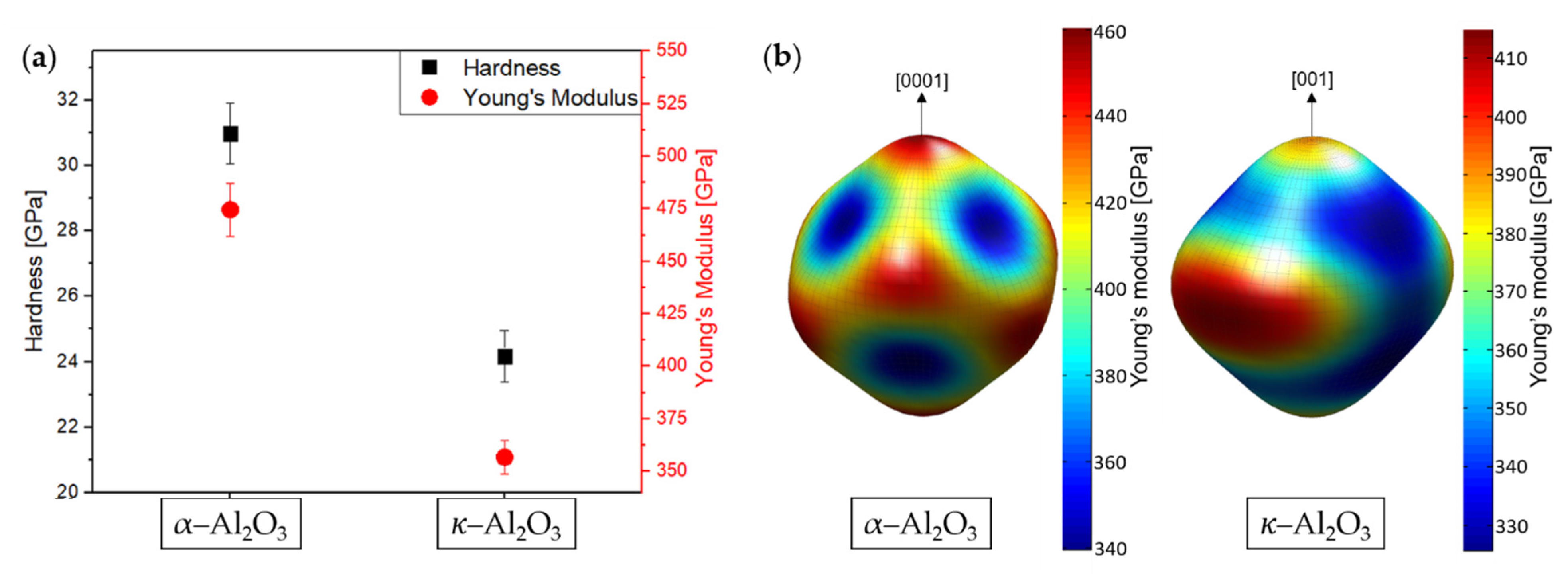
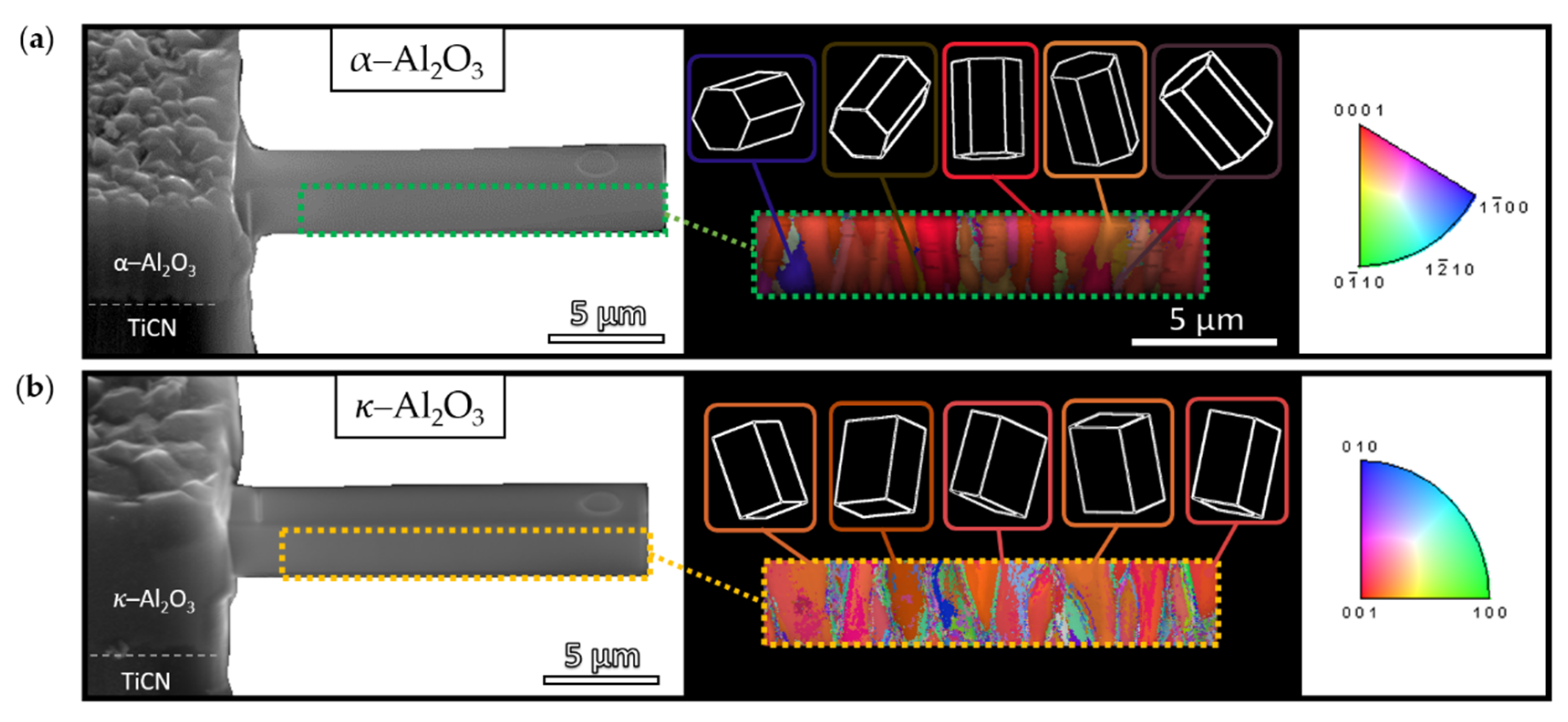
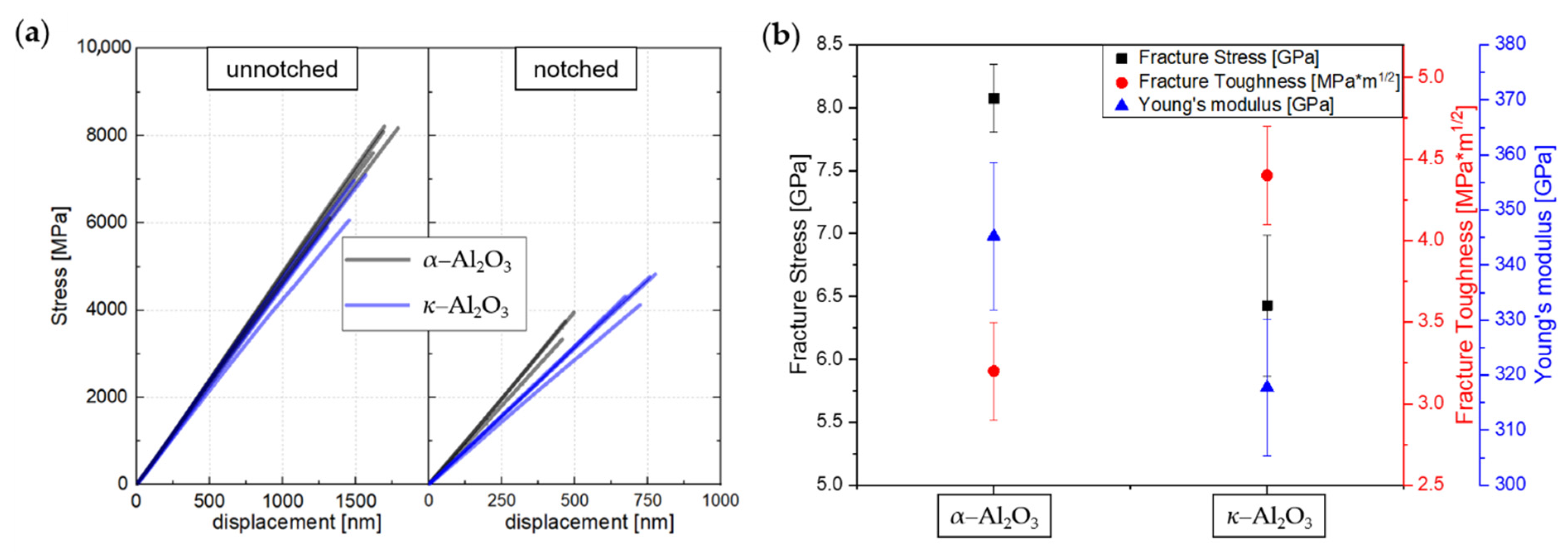
3.2. Mechanical Properties

To investigate the hardness and Young’s modulus of the coatings, nanoindentation was applied; the results are shown in Figure 3a. Both hardness and Young’s modulus are significantly higher for the α–Al2O3 compared to the κ–Al2O3 coating. The α–Al2O3 exhibits a hardness and Young´s modulus of 31.0 ± 0.9 GPa and 474.6 ± 12.5 GPa, respectively, which are in the upper region of past literature [4,25]. A hardness of 24.2 ± 0.8 GPa and a Young’s modulus of 356.8 ± 7.9 GPa were determined for the κ–Al2O3, which corresponded with the values reported in a study conducted by Ruppi et al [4]. To support the experimental data, the direction-dependent Young’s modulus of the trigonal and the orthorhombic unit cell of α– and κ–Al2O3, respectively, were calculated from single crystal elastic constants using the software package DECcalc [18,19,20], and are shown in Figure 3b, clearly highlighting the anisotropic behavior. The maximum of the calculated Young’s modulus of 460 GPa of the α–Al2O3 occurs along the [0001] direction and thus matches with the value obtained by nanoindentation. In the case of κ–Al2O3, the calculated Young’s modulus along the [001] direction amounts to 393 GPa and is thus higher compared to the experimentally determined value. However, as shown in the EBSD map of κ–Al2O3 (Figure 2b), a (001) fiber texture with a certain (013) contribution can be observed. Grains oriented in the [013] direction deviate approximately 20° from the [001] direction, resulting in a calculated Young’s modulus of 368 GPa, and this explains the lower Young’s modulus value determined by nanoindentation. A theoretical investigation using ab initio calculations by Holm et al. also corroborated that the α–Al2O3 exhibited a higher Young’s modulus than the κ–Al2O3 [20].
In order to gain information on the fracture properties, micro-cantilever bending tests were performed on both coatings. Figure 4a,b displays representative SEM images of the investigated micro-cantilevers and the corresponding IPF-Y (out-of-plane) EBSD maps of the α– and κ–Al2O3 coatings, respectively. As can be seen in the IPF-Y EBSD maps, both coatings exhibit columnar grain growth in the [001] direction. However, as indicated by the differently tilted hexagonal cells of α–Al2O3 in Figure 4a, grains with orientations other than the (0001) also exist in the lower area of the micro-cantilevers, i.e., closer to the TiCN/α–Al2O3 interface, suggesting competitive growth, which is commonly observed for CVD α–Al2O3 coatings [1,26]. It should be mentioned that the micro-cantilever was prepared approximately 1 µm above the TiCN/α–Al2O3 interface; thus, the nucleation zone of the α–Al2O3 is not visible in the EBSD scan. As indicated by the orthorhombic cell of the κ–Al2O3 coating in Figure 4b, grains of the κ–Al2O3 coating deviate slightly from the [001] direction, which confirms the results of the XRD measurements and the EBSD pole figures (Figure 2b).
Figure 5a displays the recorded stress–deflection curves of the unnotched and notched micro-cantilevers of α–and κ–Al2O3, which shows perfect linear elastic behavior until brittle fracture occurs. It is evident that the stress–deflection curves of both the notched and unnotched micro-cantilevers of α–Al2O3 are steeper compared to κ–Al2O3. Thus, the micro-mechanical bending tests indicate a higher Young´s modulus of α–Al2O3, which correlates well with the trend of the Young’s moduli determined by nanoindentation. However, as shown in Figure 5b, the absolute values for the Young´s modulus as determined from the unnotched micro-cantilevers of α– (345.2 ± 13.4 GPa) and κ–Al2O3 (317.8 ± 12.4 GPa) are significantly lower compared to the values obtained from the nanoindentation experiments and past literature values [4,25]. Several authors have reported a possible underestimation when evaluating the Young´s modulus from micro-cantilever bending tests. Matoy et al. [21] highlighted possible reasons for the underestimation: (i) additional deflection resulting from shear stresses in thick and short micro-cantilevers and (ii) deformation of the micro-cantilever support, which may lead to minor rotation of the whole micro-cantilever. For these reasons, micro-cantilevers should be prepared with an aspect ratio of (bending length/width) ≥ 6 to accurately assess the Young’s modulus, as shown by Armstrong et al. However, since the micro-cantilevers investigated in this study had an aspect ratio of approximately six, it can be assumed that there were further reasons than those mentioned above for underestimating the Young’s modulus. As reported in literature and confirmed by our calculations in Figure 3b, α– and κ–Al2O3 exhibit highly anisotropic mechanical properties. Thus, different stress fields caused by nanoindentation and micro-cantilever bending tests may explain the deviation of the Young´s modulus values [22,26,27]. The resulting fracture stress and fracture toughness from the micro-cantilever bending tests are illustrated in Figure 5b. α–Al2O3 exhibits a fracture stress of 8.1 ± 0.3 GPa and a fracture toughness of 3.2 ± 0.3 MPa*m1/2, which corresponds with the values given in previous literature [28]. κ–Al2O3, compared to α–Al2O3, shows a lower fracture stress of 6.4 ± 0.6 GPa and a higher fracture toughness of 4.4 ± 0.3 MPa*m1/2. It should be emphasized that fracture stress and fracture toughness of CVD κ–Al2O3 coatings have not been reported before. However, it is well known that a higher hardness leads to higher fracture stress values in brittle materials [29]. This is consistent with the fact that hardness of α–Al2O3 is significantly higher than κ–Al2O3 (Figure 3). Additionally, the lower value of fracture toughness of α–Al2O3 compared to κ–Al2O3 is in agreement with literature, as a material strength enhancement is accompanied with a toughness decrease [30,31].
Figure 6 displays representative fracture cross-sections of both unnotched and notched micro-cantilevers. An investigation of the fracture cross-sections shows that the notched micro-cantilevers fractured exactly at the FIB-fabricated notch, while the unnotched micro-cantilevers failed in the immediate vicinity of their origin. For the unnotched micro-cantilevers, a clear difference in the fracture cross-sections can be observed between α– and κ–Al2O3. While the fracture cross-section of α–Al2O3 exhibits grains with both smooth and heavily facetted fracture surfaces, κ–Al2O3 displays an entirely smooth fracture cross-section. According to prior literature, step-like fracture surfaces of α–Al2O3 grains, as are visible in the lower part of the micro-cantilever in Figure 6 (marked by arrows), can be found when grains are aligned for fracture on the basal plane [28,32]. Furthermore, (0001) oriented single crystalline α–Al2O3, where fracture occurs on the prism planes, is reported to exhibit smooth fracture surfaces [28,32]. This corresponds with the observation from the IPF-Y EBSD maps of the micro-cantilevers in Figure 4a, which shows randomly oriented grains in the lower part of the micro-cantilevers and highly (0001) oriented grains at the top of the micro-cantilevers. In summary, fracture surfaces of the unnotched and notched micro-cantilevers of α– and κ–Al2O3 display regions with both trans-crystalline fracture, where cleavage occurs on crystallographic planes, and intergranular fracture, where failure occurs along grain boundaries.

4. Conclusions

Within this study, α–and κ–Al2O3 coatings were deposited by thermal CVD. These coatings were evaluated and compared to each other in terms of their microstructure and their mechanical properties. The α–Al2O3 coating was composed of pyramidal grains with an average grain size diameter of 1.3 ± 0.5 µm, while the κ–Al2O3 coating consisted of larger and less sharp-edged grains with an average grain size diameter of 1.6 ± 0.6 µm. In both coatings, columnar grain growth and fiber textures were observed. While the α–Al2O3 coating exhibited a distinct (0001) fiber texture, the κ–Al2O3 coating showed a (001) fiber texture with a certain (013) contribution. Hardness and Young’s modulus values of 31.0 ± 0.9 GPa and 474.6 ± 12.5 GPa, respectively, were observed for the α–Al2O3 coating. In comparison, significantly lower hardness and Young’s modulus values of 24.2 ± 0.8 GPa and 356.8 ± 7.9 GPa, respectively, were determined for the κ–Al2O3 coating. The higher determined Young’s modulus of the α–Al2O3 compared to κ–Al2O3 coating was consistent with the direction-dependent Young’s modulus calculated from single crystal elastic constants. A fracture stress of 8.1 ± 0.3 GPa was observed for the α–Al2O3 coating, while the κ–Al2O3 coating exhibited a lower value of 6.4 ± 0.6 GPa. The opposite behavior was observed for the fracture toughness, where α–Al2O3 exhibited a fracture toughness of 3.2 ± 0.3 MPa*m1/2 and κ–Al2O3 a fracture toughness of 4.4 ± 0.3 MPa*m1/2. In conclusion, the present work provides a fundamental comparison of the micromechanical properties of CVD α–and κ–Al2O3 coatings.

Author Contributions

Conceptualization, F.K.; methodology, F.K. and M.T.; validation, F.K. and M.T.; formal analysis, F.K.; investigation, F.K. and M.T.; resources, C.C.; writing—original draft preparation, F.K.; writing—review and editing, M.T., C.C., and N.S.; visualization, F.K.; supervision, M.T. and N.S.; project administration, N.S.; funding acquisition, C.C. and N.S. All authors have read and agreed to the published version of the manuscript.

Funding

The authors gratefully acknowledge the financial support under the scope of the COMET program within the K2 Center “Integrated Computational Material, Process and Product Engineering (IC-MPPE)” (Project No 859480). This program is supported by the Austrian Federal Ministries for Climate Action, Environment, Energy, Mobility, Innovation and Technology (BMK) and for Digital and Economic Affairs (BMDW), represented by the Austrian research funding association (FFG), and the federal states of Styria, Upper Austria and Tyrol.

Institutional Review Board Statement

Not applicable.

Informed Consent Statement

Not applicable.

Data Availability Statement

Data are contained within the article. Raw data are available on request.

Conflicts of Interest

The authors declare no conflict of interest.

References

  1. Mitterer, C. PVD and CVD Hard Coatings; Elsevier Ltd.: Cham, Switzerland, 2014. [Google Scholar] [CrossRef]
  2. Schleinkofer, U.; Czettl, C.; Michotte, C. Coating Applications for Cutting Tools; Elsevier Ltd.: Cham, Switzerland, 2014. [Google Scholar] [CrossRef]
  3. Garcia, J.; Pitonak, R.; Weißenbacher, R.; Köpf, A.; Soldera, F.; Suarez, S.; Miguel, F.; Pinto, H.; Kostka, A.; Mücklich, F. Design and characterization of novel wear resistant multilayer CVD coatings with improved adhesion between Al2O3 and Ti(C,N). Adv. Eng. Mater. 2010, 12, 929–934. [Google Scholar] [CrossRef]
  4. Ruppi, S.; Larsson, A.; Flink, A. Nanoindentation hardness, texture and microstructure of α-Al2O3 and κ-Al2O3 coatings. Thin Solid Films 2008, 516, 5959–5966. [Google Scholar] [CrossRef]
  5. Levin, I.; Brandon, D. Metastable alumina polymorphs: Crystal structures and transition sequences. J. Am. Ceram. Soc. 2005, 81, 1995–2012. [Google Scholar] [CrossRef]
  6. Ruppi, S. Advances in chemically deposited wear resistant coatings. J. Phys. IV 2001, 11, 847–859. [Google Scholar] [CrossRef]
  7. Ruppi, S.; Larsson, A. Chemical vapour deposition of κ-Al2O3. Thin Solid Films 2001, 388, 50–61. [Google Scholar] [CrossRef]
  8. Larsson, A.; Ruppi, S. Microstructure and properties of CVD γ-Al2O3 coatings. Int. J. Refract. Met. Hard Mater. 2001, 19, 515–522. [Google Scholar] [CrossRef]
  9. Hochauer, D.; Mitterer, C.; Penoy, M.; Michotte, C.; Martinz, H.; Kathrein, M. Thermal stability of doped CVD κ-Al2O3 coatings. Surf. Coat. Technol. 2010, 204, 3713–3722. [Google Scholar] [CrossRef]
  10. Skogsmo, J.; Halvarsson, M.; Vuorinen, S. Microstructural study of the κ-Al2O3 → α-Al2O3 transformation in CVD κ-Al2O3. Surf. Coat. Technol. 1992, 54–55, 186–192. [Google Scholar] [CrossRef]
  11. Moreno, M.; El Azhari, I.; Apel, D.; Meixner, M.; Wan, W.; Pinto, H.; Soldera, F.; Müklich, F.; Garcia, J. Design of comb crack resistant milling inserts: A comparison of stresses, crack propagation, and deformation behavior between Ti(C,N)/α-Al2O3 and Zr(C,N)/α-Al2O3 CVD coatings. Crystals 2021, 11, 493. [Google Scholar] [CrossRef]
  12. Hansson, P.; Halvarsson, M.; Vuorinen, S. Characterisation of the κ-Al2O3→α-Al2O3 transformation in different single layer coatings of CVD κ-Al2O3. Surf. Coat. Technol. 1995, 76–77, 256–264. [Google Scholar] [CrossRef]
  13. Osada, A.; Nakamura, E.; Homma, H.; Hayahi, T.; Oshika, T. Wear mechanism of thermally transformed CVD Al2O3 layer. Int. J. Refract. Met. Hard Mater. 2006, 24, 387–391. [Google Scholar] [CrossRef]
  14. Ruppi, S. Deposition, microstructure and properties of texture-controlled CVD α-Al2O3 coatings. Int. J. Refract. Met. Hard Mater. 2005, 23, 306–316. [Google Scholar] [CrossRef]
  15. Ruppi, S. Enhanced performance of α-Al2O3 coatings by control of crystal orientation. Surf. Coat. Technol. 2008, 202, 4257–4269. [Google Scholar] [CrossRef]
  16. Hochauer, D.; Mitterer, C.; Penoy, M.; Michotte, C.; Martinz, H.; Kathrein, M. Titanium doped CVD alumina coatings. Surf. Coat. Technol. 2008, 203, 350–356. [Google Scholar] [CrossRef]
  17. Oliver, W.C.; Pharr, G.M. An improved technique for determining hardness and elastic modulus using load and displacement sensing indentation experiments. J. Mater. Res. 1992, 7, 1564–1583. [Google Scholar] [CrossRef]
  18. Manns, T.; Scholtes, B. DECcalc—A program for the calculation of diffraction elastic constants from single crystal coefficients. Mater. Sci. Forum 2011, 681, 417–419. [Google Scholar] [CrossRef]
  19. Gladden, J.R.; So, J.H.; Maynard, J.D.; Saxe, P.; Le Page, Y. Reconciliation of ab initio theory and experimental elastic properties of Al2O3. Appl. Phys. Lett. 2004, 85, 392. [Google Scholar] [CrossRef] [Green Version]
  20. Holm, B.; Ahuja, R.; Yourdshahyan, Y.; Johansson, B.; Lundqvist, B.I. Elastic and optical properties ofα- andκ−Al2O3. Phys. Rev. B 1999, 59, 12777–12787. [Google Scholar] [CrossRef]
  21. Matoy, K.; Schönherr, H.; Detzel, T.; Schöberl, T.; Pippan, R.; Motz, C.; Dehm, G. A comparative micro-cantilever study of the mechanical behavior of silicon based passivation films. Thin Solid Films 2009, 518, 247–256. [Google Scholar] [CrossRef]
  22. Gere, J.M.; Timoshenko, S.P. Mechanics of Materials, 3rd ed.; Springer-Science-Business Media, B.V.: Berlin/Heidelberg, Germany, 1991. [Google Scholar] [CrossRef]
  23. Gates-Rector, S.; Blanton, T. The powder diffraction file: A quality materials characterization database. Powder Diff. 2019, 34, 352–360. [Google Scholar] [CrossRef] [Green Version]
  24. Stylianou, R.; Tkadletz, M.; Schalk, N.; Penoy, M.; Czettl, C.; Mitterer, C. Effects of reference materials on texture coefficients determined for a CVD α-Al2O3 coating. Surf. Coat. Technol. 2019, 359, 314–322. [Google Scholar] [CrossRef]
  25. Chien, H.; Gao, M.C.; Miller, H.M.; Rohrer, G.S.; Ban, Z.; Prichard, P.; Liu, Y. Microtexture and hardness of CVD deposited α-Al2O3 and TiCxN1−x coatings. Int. J. Refract. Met. Hard Mater. 2009, 27, 458–464. [Google Scholar] [CrossRef]
  26. Shoja, S.; Mortazavi, N.; Lindahl, E.; Norgren, S.; Bäcke, O.; Halvarsson, M. Microstructure investigation of textured CVD alumina coatings. Int. J. Refract. Met. Hard Mater. 2020, 87, 105125. [Google Scholar] [CrossRef]
  27. Fischer-Cripps, A.C. Introduction to Contact Mechanics, 2nd ed.; Springer: New South Wales, Australia, 2007. [Google Scholar]
  28. Norton, A.; Falco, S.; Young, N.; Severs, J.; Todd, R. Microcantilever investigation of fracture toughness and subcritical crack growth on the scale of the microstructure in Al2O3. J. Eur. Ceram. Soc. 2015, 35, 4521–4533. [Google Scholar] [CrossRef]
  29. Zhang, P.; Li, S.; Zhang, Z. General relationship between strength and hardness. Mater. Sci. Eng. A 2011, 529, 62–73. [Google Scholar] [CrossRef]
  30. Ritchie, R. The conflicts between strength and toughness. Nat. Mater. 2011, 10, 817–822. [Google Scholar] [CrossRef]
  31. Daniel, R.; Meindlhumer, M.; Zalesak, J.; Baumegger, W.; Todt, J.; Ziegelwanger, T.; Keckes, J.F.; Mitterer, C.; Keckes, J. Multi-scale interface design of strong and damage resistant hierarchical nanostructured materials. Mater. Des. 2020, 196, 109169. [Google Scholar] [CrossRef]
  32. Konstantiniuk, F.; Tkadletz, M.; Kainz, C.; Czettl, C.; Schalk, N. Mechanical properties of single and polycrystalline α-Al2O3 coatings grown by chemical vapor deposition. Surf. Coat. Technol. 2021, 410, 126959. [Google Scholar] [CrossRef]
Figure 1. X-ray diffractograms of CVD (a) α–Al2O3 and (b) κ–Al2O3 coatings deposited on cemented carbide substrates with a TiN base layer and a TiCN intermediate layer.
Coatings 11 01359 g001
Figure 2. SEM images of the as-deposited coatings and IPF EBSD maps combined with the SEM images of the polished surfaces as well as the corresponding calculated EBSD pole figures of (a) α–Al2O3 and (b) κ–Al2O3 coatings.
Coatings 11 01359 g002
Figure 3. (a) Hardness and Young’s modulus of the α– and κ–Al2O3 coating evaluated by nanoindentation and (b) direction dependent Young’s modulus of α– and κ–Al2O3 calculated from single crystal constants. Please note the different scale bars for α– and κ–Al2O3.
Coatings 11 01359 g003
Figure 4. SEM images and IPF-Y EBSD maps of an exemplary (a) α– and (b) κ–Al2O3 micro-cantilever, including the unit cells of selected grains.
Coatings 11 01359 g004
Figure 5. (a) Stress–displacement curves of the unnotched and notched micro-cantilevers. (b) Fracture stress, fracture toughness and Young’s modulus determined from the micro-cantilever bending tests.
Coatings 11 01359 g005
Figure 6. Post-mortem fracture cross-sections of the unnotched and notched micro-cantilevers. The arrows in the cross-section of the unnotched α–Al2O3 mark step-like fracture grains.
Coatings 11 01359 g006
Publisher’s Note: MDPI stays neutral with regard to jurisdictional claims in published maps and institutional affiliations.

