1. Introduction
The need for functional materials always increases—many systems and their parts or sections must be durable and resistant to chemical or thermal effects and corrosion. Inevitably, surface treatment is necessary for performance, longevity, and quality purposes. One of the most effective ways to prolong the lifetime of certain parts or systems is protective coatings. Ceramic coatings deposited employing plasma spray technology become a viable alternative to organic and polymer-based coatings for surface protection applications. The most frequently used metal oxide ceramics are alumina, zirconia, titania, yttria, and their composites materials. Thermal and plasma spraying methods appear as the most common ways to form a protective ceramic coating on the material surface [
1].
Thermal spray technology has several advantages which make it attractive for the large-scale applications. These include the low cost, flexibility, simplicity of operation, fast deposition rates, possibility to coat on large areas and various shapes of substrates, and a variety of materials can be used as a substrate for the coating. Thermal plasma jets are characterized by high velocities (100–2500 m/s) and high temperatures (2000–14,000 K). Thus, it gives the ability to spray a wide variety of materials from metals to ceramics [
1,
2,
3,
4,
5,
6,
7,
8,
9,
10]. Moreover, almost any ceramics or their composites with high melting points can be melted and deposited due to the high temperature of the plasma flame [
2,
3,
10]. In addition, the plasma jet temperature is easily managed by adjusting the torch power, gas flow rate, or type of gas and at the same time controlling the properties of the deposited coatings [
1,
2,
3,
4,
5,
6,
7,
8,
9,
10].
Plasma sprayed ceramic coatings have many excellent properties, such as wear and corrosion resistance and high-temperature resistance. They are widely used in various industrial equipments [
4] and are mainly applicable where deterioration and wear resistance are simultaneously required [
5]. Alumina coatings today are widely used as high-performance ceramic coatings in a range of industrial applications. Such wide applications are related to high hardness, chemical inertness, and low cost compared to other ceramic materials. To improve the coating quality, such as brittleness and friction reduction, and to increase the fracture toughness and corrosion resistance, the particular amount of titanium oxide (TiO
2) to alumina powder is usually doped [
7,
8,
9,
11,
12]. The addition of TiO
2 reduces the microhardness of alumina coatings [
13,
14,
15,
16]. However, TiO
2 improves the corrosion resistance, reduces the wear rate, and enhances the elastic modulus [
17]. V.C. Misra et al. [
17] demonstrated that the tribological properties of Al
2O
3 coatings, prepared using argon-hydrogen plasma, strongly depend on the process parameters and could be used in an atmosphere of dry air and dry nitrogen.
M. Wang et al. [
18] found that Al
2O
3-13 wt.% TiO
2 coatings sprayed using argon-helium plasma remained stable after thermal shock testing under temperatures below 800 °C. Al
2O
3/YSZ composite coatings demonstrated a higher oxidation resistance at high temperatures (~1050 °C) compared to Al
2O
3 coatings [
19]. S. Jia et al. [
9] observed that an increase of TiO
2 content in alumina coatings enhanced the corrosion resistance and reduced the γ-Al
2O
3 phase content, porosity, and thermal insulation properties. M.A. Zavareh et al. [
5] indicated that alumina-titania coatings are suitable for the protection of carbon steel surfaces from the corrosion. S. Matthews et al. [
20] demonstrated that the relative intensity of γ-Al
2O
3 peaks to α-Al
2O3 peaks decreased at 700 °C heating temperature for alumina coatings. V. Sharma et al. [
21] observed that alumina coatings protected an AISI 1020 steel surface from oxidation at 900 °C. However, delamination and formation of cracks in Al
2O
3 coatings were found after 50 heating cycles. X. Wang et al. [
22] demonstrated that the microstructure of Al
2O
3-Y
2O
3 and Al
2O
3-Y
2O
3-TiO
2 coatings remained unchanged after heat treatment at 800 °C for 2 h. Meanwhile, crystallization and structural changes at higher temperatures were obtained.
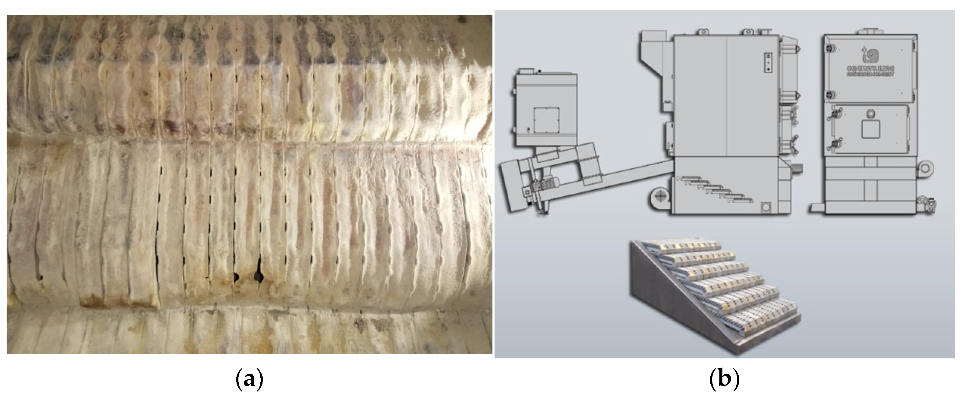
Based on the scientific literature review performed, alumina and alumina-based ceramic coatings could be suitable for improving the surface properties of the fire grate of a straw pellet furnace, made from cast steel and highly vulnerable to corrosion. It would allow avoiding regular grate replacement yearly or every two years depending on the workload (
Figure 1).
High-quality cast iron fire grates, typically used in straw pellet furnaces, are more expensive than steel grates because of various alloying elements, such as iron, chromium, nickel, etc. The level of anticorrosion protection of straw pellet furnaces could be increased, and exploitation costs could be reduced, proposing cheaper steel with a protective ceramic coating instead of cast iron. This technology has not been implemented in the industry so far, and not much research has been conducted in this field. Various researchers have investigated the thermal and chemical resistance of plasma sprayed ceramic coatings deposited using argon or argon-hydrogen plasma [
1,
4,
5,
6,
9,
20]. However, research concerning the formation of ceramic coatings using air-hydrogen plasma via atmospheric pressure plasma spraying is hard to find in the scientific literature. Thus, it is essential to estimate the influence of various parameters on the structure of ceramic surfaces.
It should be noted that the temperature inside a furnace is about 500–600 °C. Meanwhile, the phase (structural) changes of Al
2O
3 coatings in the range of 500–700 °C are almost insignificant [
9,
17]. During straw combustion, potassium, sodium, and chlorine compounds form in the combustion products, and reactions with furnace surfaces occur, which cause intense corrosion damage. Chlorine is released in HCl and Cl
2, reacting with the fire grate heating surface, causing the most severe active oxidation corrosion. As a result, the lifetime of metallic grates is drastically reduced. Thus, the deposition of ceramic coatings on metal surfaces could significantly improve the lifetime of the fire grate of a biomass furnace. In most cases, the surface properties can be improved with the addition of selected additives that alter the surface properties of the coating. For this purpose, alongside alumina feedstock powder, the addition of titania was selected and used.
The main aims were to deposit Al2O3 and Al2O3-13 wt.% TiO2 coatings using air-hydrogen plasma via plasma spraying and to investigate the effect of the cycling heat treatment on the microstructure, phase composition, and thermal resistance properties of sprayed coatings for application in biomass firing plants.
The part of the research results were obtained in the collaboration with the Enerstena Group.
2. Materials and Methods
Al
2O
3 and Al
2O
3-13 wt.% TiO
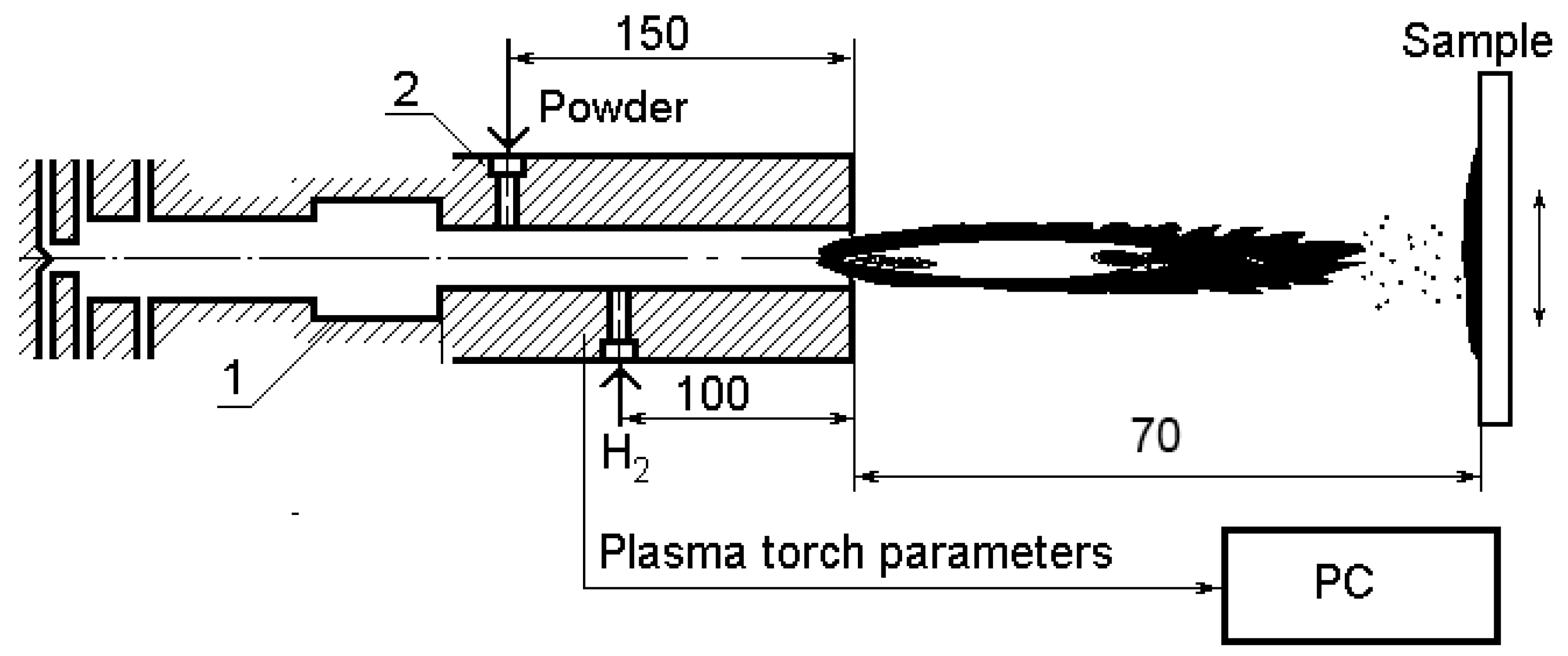
2 coatings were deposited on steel (P265GH) substrate at atmospheric pressure using a direct current (DC) plasma torch developed at Lithuanian Energy Institute (Kaunas, Lithuania) [
23,
24]. A DC plasma torch has a stable electric arc and more efficient operating characteristics than alternating current (AC) arc discharge systems. The electric discharge is generated between a hot button-type hafnium cathode and an anode made of high purity copper. The primary plasma forming gas-air passes through the electric arc, where dissociation and ionization processes occur until plasma forms. DC plasma spraying is the most versatile of all thermal spray processes concerning high-speed jets and extremely high plasma temperatures. A DC plasma generator is water-cooled intensively to prevent melting and to minimize erosion of electrodes. The DC power supply system and supplying equipment to ensure stable plasma torch operating conditions are described elsewhere [
23,
24]. A schematic view of the experimental setup is shown in
Figure 2.
The reactor is composed of a water-cooled stainless-steel tube 150 mm in length and 7 mm in internal diameter. At a distance of 100 mm from the outlet nozzle, a channel was arranged for hydrogen injection. The hydrogen flow rate increased thermal energy in the plasma jet and the melting state of the spraying powders.
The steel substrate samples of 40 mm × 10 mm × 6 mm in dimension were prepared, then blasted using metal balls to increase the surface area and chemically cleaned from impurities. Air was used as a primary plasma forming and powder carrier gas. Additionally, hydrogen was used as a secondary gas to increase the temperature of the plasma jet. The operating parameters for the deposition of coatings are presented in
Table 1. The additional bonding layer from nickel-chromium powders (MOGUL M3, Ni/Cr ratio of 80/20, MOGUL METALLIZING GmbH, Kottingbrunn, Austria) was deposited to improve the adhesion of the primary coating.
When the parameters of the plasma flow were achieved as stable and desirable, hard spherical powders were injected into the flow. The coating deposition process was performed with the powders of two different compositions under the same plasma spraying conditions. Conventional 11–84 µm size Al
2O
3 (MOGUL PC15, purity 99.8%, MOGUL METALLIZING GmbH, Kottingbrunn, Austria) and the same size Al
2O
3-13 wt.% TiO
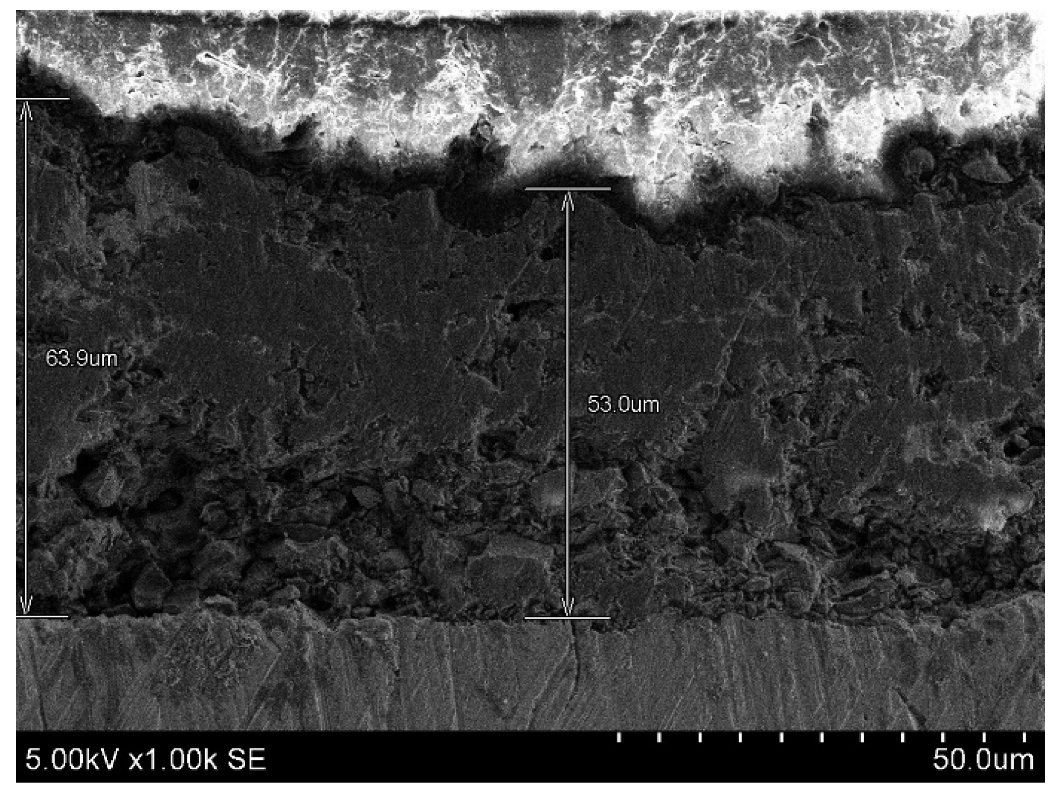
2 (MOGUL PC12, MOGUL METALLIZING GmbH, Kottingbrunn, Austria) powders were used as a feedstock material injected into the plasma torch nozzle. Before the deposition of the coatings, all powders were dried to prevent moisture from being absorbed during storage. A cross-section image of the as-sprayed alumina coating is displayed in
Figure 3. The coating thickness ranges from 50 to 65 µm, with a Ni/Cr bonding layer of approximately 15–20 µm.
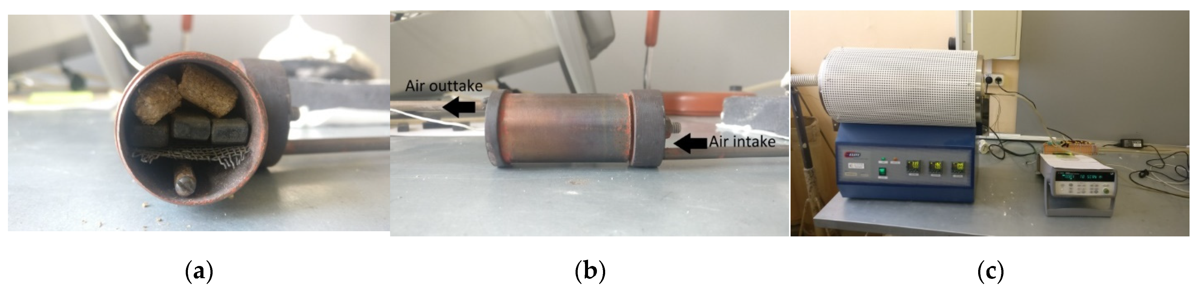
To imitate working conditions as in the biomass furnace, all produced samples (control sample of uncoated steel (P265GH)) and samples with plasma sprayed (Al
2O
3 and Al
2O
3 mixed with 13 wt.% TiO
2 coatings) were placed into a metal cylinder (90 mm long and 45 mm in diameter) filled with straw pellets (as shown in
Figure 4). The airflow was supplied into the cylinder through holes (
Figure 4b) at a constant rate of 4.7 g/s. The cylinder was inserted into the electric furnace (model TMH12/38/500-2416, Elite Thermal Systems Ltd., Market Harborough, UK) and heated up to 500 °C. During this experiment, the furnace slowly heated up, and straw pellets started to burn when the temperature reached ~400 °C. Each experimental procedure took 80 min to perform, and the variation of temperatures was measured using three thermocouples placed inside the metal cylinder.
The scheme of the experimental setup inside the metal tube is displayed in
Figure 5. The first thermocouple was placed under the samples, while the second and third were placed on the top of Al
2O
3 and Al
2O
3-13 wt.% TiO
2 coatings, respectively. After finishing the heating experiment, the specimens were left in the furnace to cool down for several hours. At this stage, one cycle of heat treatment of the samples was completed. After five heating cycles, the surface morphology, phase and elemental composition of all three samples were investigated.
All samples were cleaned using an ultrasonic cleaner after every five cycles of heating before the characterization. The surface morphology of coatings was characterized using scanning electron microscopy with a Hitachi S-3400N (SEM, Hitachi, Tokyo, Japan). The elemental composition and elemental mapping were done using energydispersive X-ray spectroscopy (Bruker Quad 5040 spectrometer, Bruker Nano GmbH, Hamburg, Germany). The measurements were performed from 1.05 mm2 surface area at four different points for each sample, and the mean values were calculated. The crystallographic structure of coatings was investigated via X-ray diffraction (XRD) with Bruker D8 (Bruker, Hamburg, Germany) equipment using CuKα (λ = 0.154059 nm) radiation with 2θ in the range from 20 to 70°. The five-cycle heating procedure was repeated several times to understand the long-term impact on the samples, and it was finished after 25 cycles of heat treatment.
3. Results and Discussion
Variation of the temperature inside the heated metal cylinder during the combustion of straw pellets is presented in
Figure 6. The combustion of straw pellets occurred on the top of the samples. The bottom surface temperature was lower than the top and related to the constant airflow from the bottom right side of the cylinder. A rapid temperature rise was observed at 17 min when the straw pellets started to burn. The peak temperature was observed after 25 min, and it was between 520–550 °C. The temperature on the upper surface of the samples was about 100 °C higher than at the bottom side during the burning of the straw pellets. After the burning process, the temperature on the top and the bottom of the samples decreased to 450 °C and 400 °C, respectively.
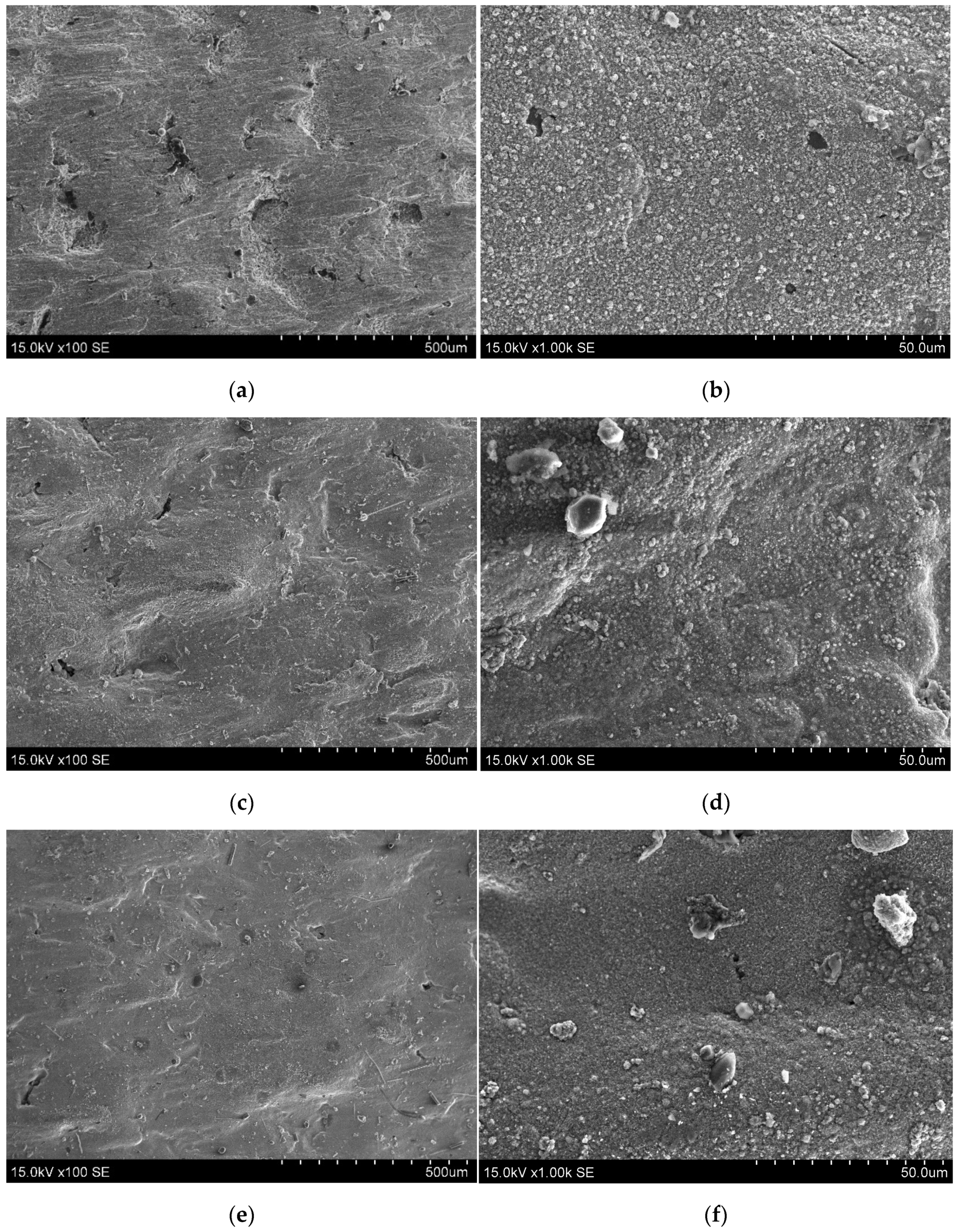
Before the heating experiments (
Figure 7a,b), the steel surface is relatively smooth and clean. After just 5 heat treatment cycles (
Figure 7c,d), a change of material morphology is already visible. Many slag particles were detected, which were not detached from the surface even after ultrasonic cleaning. SEM images indicated that hot combustion products caused structural damage to the steel surface. The continuous heat treatment did even more damage to the surface of the uncoated steel sample. More various size (from 1 to 10 µm) particles can be seen on the surface and several cracks formed after 15 (
Figure 7e,f) and 25 (
Figure 7g,h) heating cycles.
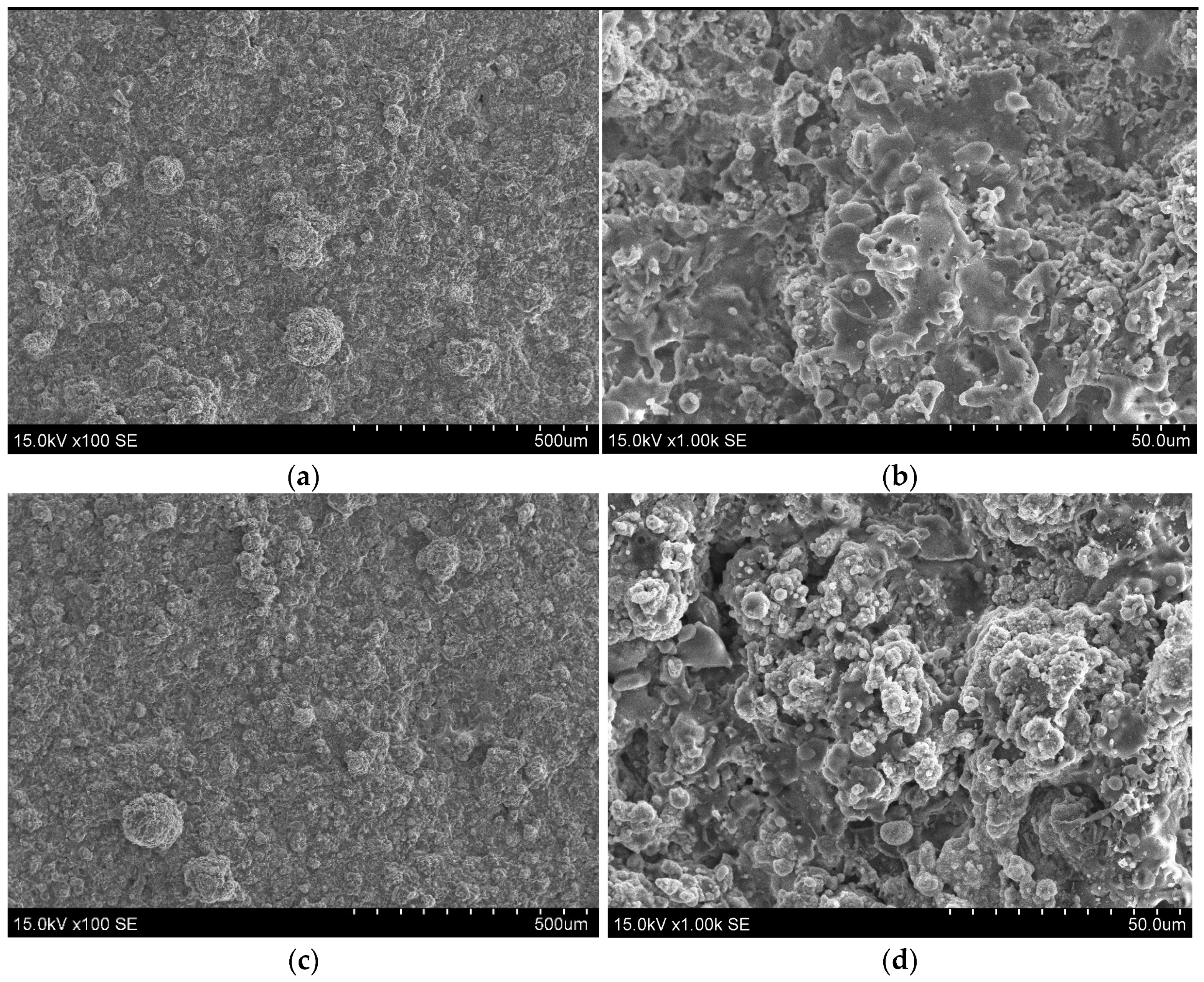
Before heat treatment of the Al
2O
3 coating (
Figure 8a,b), its surface consists of splats and semi-molten particles. No apparent defects, such as cracks or delamination, were observed in the surface structure. After 5 heating cycles (
Figure 8c,d), the surface view is somewhat similar to the surface of the untreated alumina coating. However, the quantity of small particles is higher. Much like in the steel sample case, many of those tiny particles are leftover products of burned straw pellets that were not cleaned thoroughly, but overall, the coated surface remained intact. After 15 (
Figure 8e,f) heating cycles, no additional changes in surface morphology were observed. However, after 25 heating cycles, a visibly larger melted area appears (
Figure 8h), but the overall structure and morphology of the coatings seem to be similar, but with some defects starting to take shape.
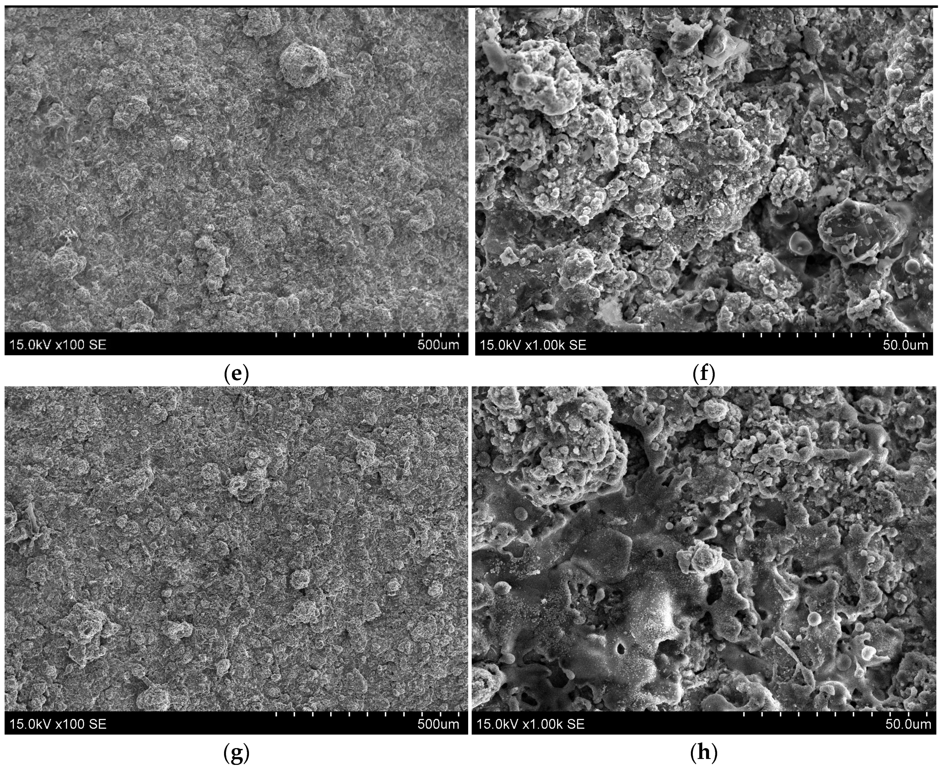
The surface morphology of Al
2O
3-13 wt.% TiO
2 coating is presented in
Figure 9. The micrographs show splats and semi-molten particles on the untreated surface: cracks or delamination zones are not visible (
Figure 9a,b). After 5 heating cycles (
Figure 9c,d), no visible changes can be observed using 100- and 1000-times magnification. After 15 cycles (
Figure 9e,f), no cracks are observed; however, some height differences can be seen, since there are some brighter and darker areas. Lastly, after 25 heating cycles (
Figure 9g,h), not much difference can be observed; there are some darker and brighter areas on the coating, but no significant damage on the surface was found. The results confirm that Al
2O
3 and Al
2O
3-13 wt.% TiO
2 coatings significantly improved resistance to chemical reactions occurring during the combustion processes of straw pellets compared to uncoated steel substrates.
The elemental composition on the surface of sprayed coatings was analyzed using energy-dispersive X-ray spectroscopy. Surfaces of the steel and coatings were tested before the heat treatment and after 5, 15, and 25 cycles, respectively. Each sample was measured in four different spots, and mean values were calculated (deviation 1%). The uncoated steel surface consists mainly of iron (93 at.%) and a small amount of oxygen (4 at.%). A low concentration of manganese (~0.9 at.%) and aluminum (1.4 at.%) due to the chemical composition of the steel was observed. Just after 5 heating cycles (
Table 2) the amount of oxygen dramatically increased to 47 at.%, while the amount of iron decreased to ~50 at.%.
The further increase in the number of treatment cycles (up to 25) did not affect the amount of oxygen on the steel’s surface. Additionally, negligible traces of silicon, potassium, calcium and sulfur were found on the surface of steel, which are products left over after the combustion reactions and were not completely removed with ultrasonic cleaning.
The elemental composition of the Al
2O
3 coating before the heat treatment was: aluminum (32 at.%), oxygen (59 at.%), nickel (6 at.%) and chromium (2 at.%) (
Table 3). Besides, small amounts of other elements also were found (carbon, iron, silicon, etc.). Chromium and nickel originated from NiCr bonding layer deposited on the substrate’s surface to increase the coating’s adhesion. After 5 heating cycles, the amount of aluminum decreased by 3% (to 29 at.%) and oxygen by 1% (to 60 at.%), the amount of nickel and chromium remained the same. Further increase in heating cycles induced only a slight variation in the elemental composition of the alumina coating. The oxygen concentration was 58 at.% and 60 at.%, after 15 and 25 treatment cycles, respectively. The amount of aluminum was slightly reduced (by 1.5–2.5 at.%) after 15 and 25 cycles compared to the amount of Al in as-sprayed Al
2O
3 coating. The highest increase of nickel to nearly 8 at.% was observed after 15 treatment cycles. However, the concentration of Ni decreased to 6 at.% after 25 treatment cycles. The amount of chromium remained unchanged throughout all heating cycles.
As-deposited Al
2O
3-13 wt.% TiO
2 coating consisted of aluminum (22 at.%), oxygen (59 at.%), titanium (4 at.%), nickel (9 at.%), and chromium (3 at.%) before the treatment (
Table 4). As in the case with the Al
2O
3 sample nickel and chromium are related to the NiCr bonding layer and small amounts of carbon, iron and silicon were found. After 5 cycles of heat treatment, there were almost no changes in elemental composition. The amount of aluminum increased by 1% (to 23 at.%) and nickel decreased by 1% (to 8 at.%). Meanwhile, the concentrations of oxygen titanium and chromium remained the same. Further increase of heating cycles (up to 25) had almost no effect on the elemental composition of the Al
2O
3-13 wt.% TiO
2 coating. It should be noted that only a minor increase of the oxygen concentration was observed after long-term heat treatment. The observed data indicate that the addition of titanium increased the stability of the elemental composition.
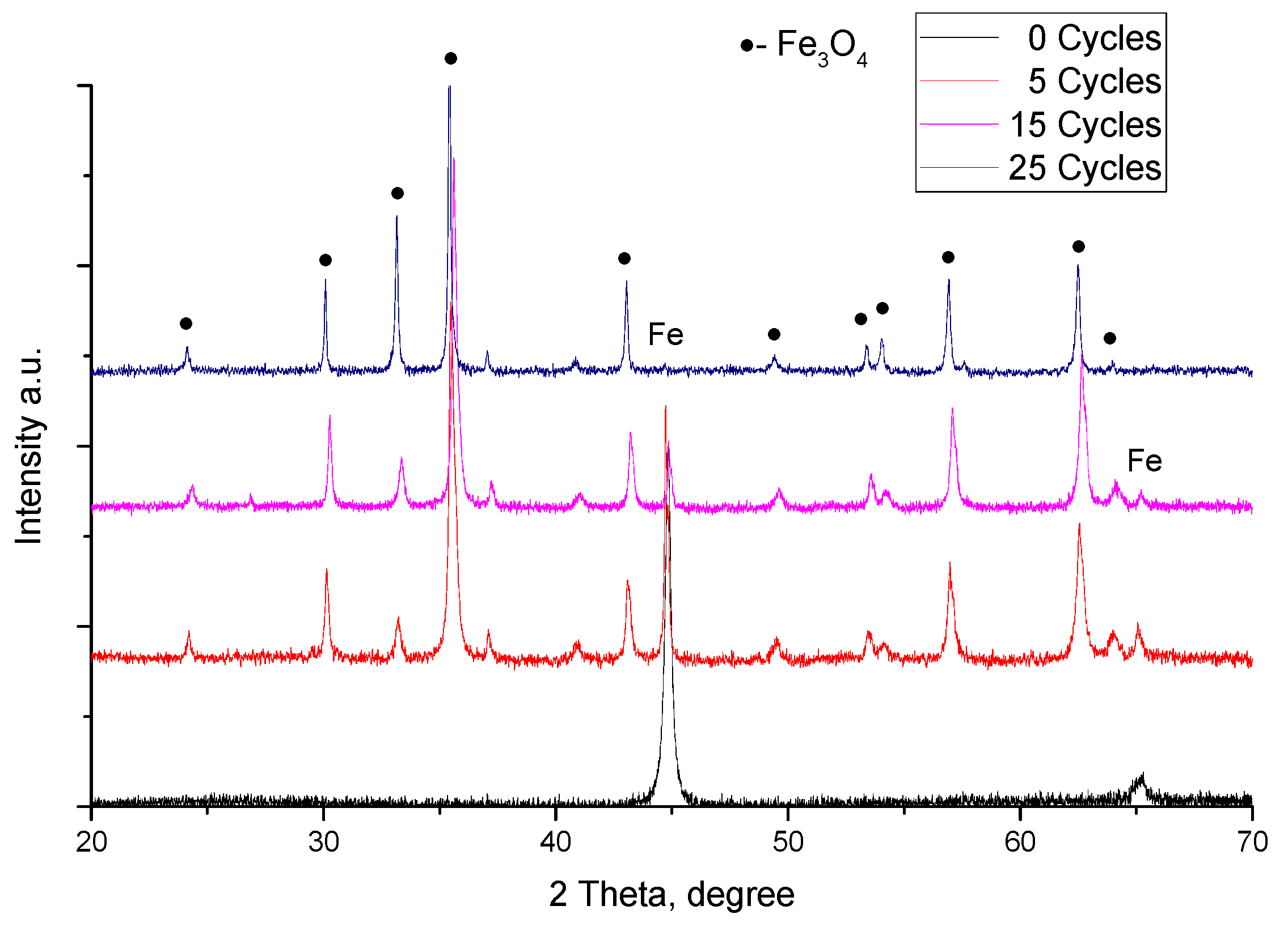
The phase composition of the uncoated P265GH steel is shown in
Figure 10. Before the heat treatment experiment, only 2 peaks of Fe at 2θ = 44.7° and 65.1° were observed. Meanwhile, after 5 heating cycles the peaks at 2θ = 24.1° 30.1° 33.2° 35.4° 43.0° 49.4° 53.4° 54.0° 56.9° 62.5° attributed to Fe
3O
4 phase were observed. It was indicated that above 570 °C, normally, a layer of Fe
2O
3 is formed on the steel surface due to oxidation and beneath this layer, Fe
3O
4 and FeO phases are formed [
21]. Whereas at temperatures below 570 °C and atmospheric pressure, only two phases are stable, magnetite (Fe
3O
4) and hematite (Fe
2O
3) [
25]. However, as was reported by R. Y. Chen, at temperatures below 700 °C, oxidation results are inconsistent and significantly affected by sample preparation methods. Therefore, the only detected phase in this sample was magnetite [
26]. Further increase of heating cycles has continually increased the intensity of Fe
3O
4 peaks. The results confirm that the steel sample was heavily damaged by corrosion during the heat treatment cycles and protection is necessary under these working conditions. It was demonstrated that the thickness of the formed iron oxide layer in steels depends on the oxidation duration type of used steel (activation energy of the steel) and temperature value (oxidation rate constant). Thus, the thickness of the Fe
3O
4 layer increased with the increase of the number of heating cycles. The intensity of the iron peak at ~44.7° decreases after 15 cycles of heating and the disappearance of this peak after 25 heating cycles indicates the formation of a thicker Fe
3O
4 layer. In addition, it was found that the degree of difficulty of iron oxides formation is in the following order: Fe
2O
3 > Fe
3O
4 > FeO. Meanwhile, the main reason for the oxidation of iron is the outward diffusion of Fe ions and the secondary reason is the inward diffusion of oxygen ions. FeO is formed on the outer surface layer at the initial stage of oxidation under the condition that the supply of Fe ions is sufficient (usually at 1000 °C or higher temperatures) [
27]. The heating temperature was relatively low in our cases, only up to 550 °C for ~10 min. Thus, the diffusion of iron ions is limited. In the case of insufficient Fe ions diffusion and sufficient oxygen ions, the formation of a Fe
3O
4 layer starts.
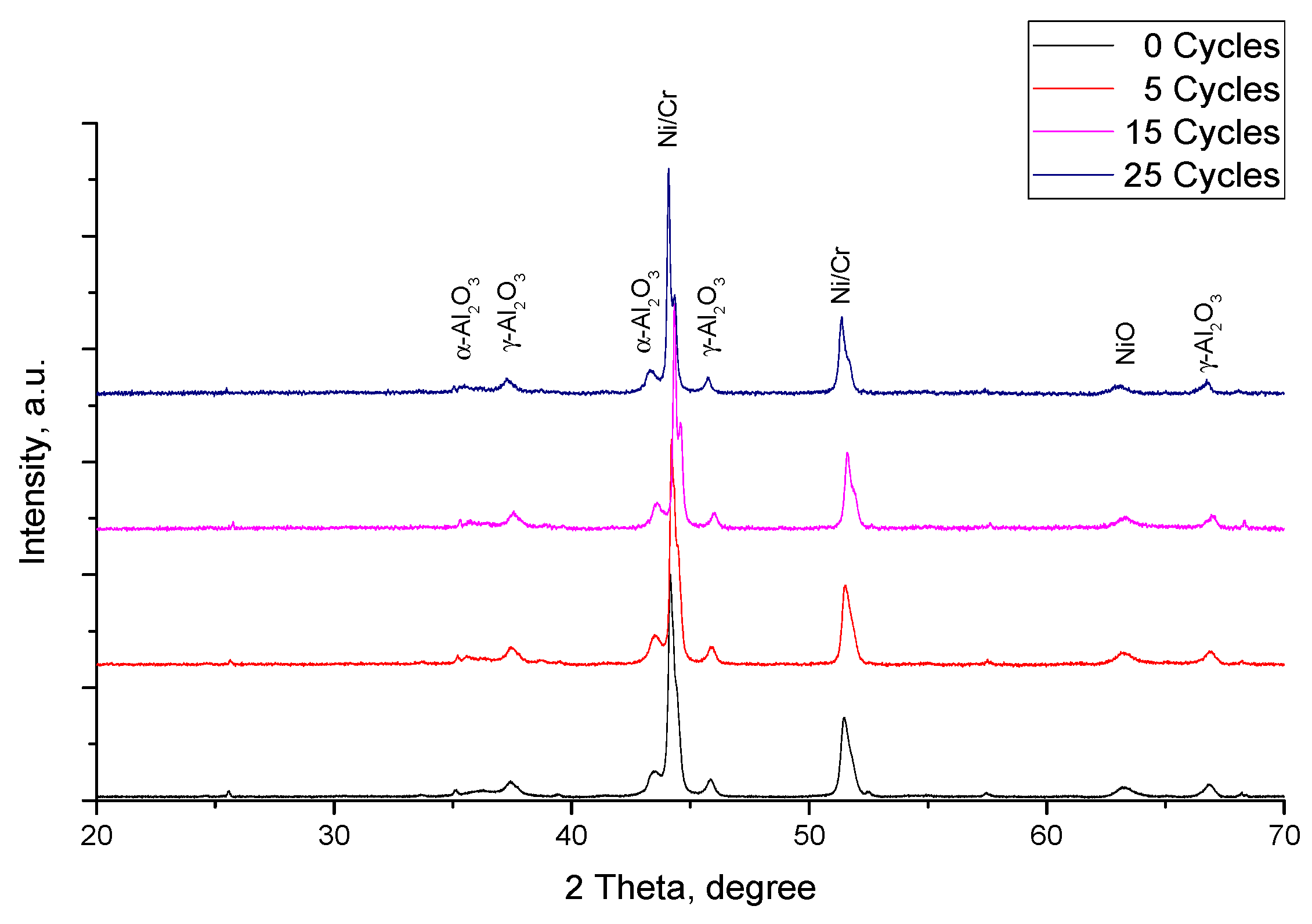
The XRD patterns of the as-sprayed Al
2O
3 coating and after cycling heat treatment are given in
Figure 11. As can be seen, there are noticeably fewer changes in the phase composition of the Al
2O
3 coating after heating (
Figure 11). The as-sprayed coating demonstrated the diffraction peaks at 2θ = 25.6° 35.7° 43.5° 57.7° and 63.1°, which were attributed to the rhombohedral α-Al
2O
3 phase [
9,
25,
28]. The γ-Al
2O
3 phase was also determined at 2θ = 37.4° 38.9° 45.9° and 67.1° [
22,
25,
28] The ratio of the highest intensity of α-Al
2O
3 (at 43.5°) and γ-Al
2O
3 (at 45.9°) peaks was 1.16 before heat treatment. The initial phase in alumina feedstock powder was only α-Al
2O
3. Thus, partial phase transformation from alpha to gamma-alumina occurred [
9,
11,
29]. It is well known that the γ phase amount in Al
2O
3 coatings is increased with the increase of the melting degree of the particle and/or the solidification rate of the alumina splats on the substrate [
11,
29]. During the rapid cooling and solidification process, the liquid droplets could nucleate and grow up forming crystalline phases as well as staying in an amorphous phase [
22]. The intensity of the alpha phase peak at 43.5° slightly increased and the peak became sharper after 5 heating cycles. As a result, the α-Al
2O
3/γ-Al
2O
3 ratio increased up to 1.49 after the first 5 heating cycles. The further increase of heating cycles enhances the intensities of α-Al
2O
3 peaks. The α-Al
2O
3/γ-Al
2O
3 ratio increased up to 1.81 after 15 cycles and the highest α-Al
2O
3/γ-Al
2O
3 ratio of 1.84 was observed after 25 cycles. It was found that the α-Al
2O
3 peak intensity increased while the γ-Al
2O
3 peak intensity remained similar. This happens because the temperature is not high enough for phase transition reactions from α-Al
2O
3 to γ-Al
2O
3 phase to occur (950–1050 °C). The temperature is high enough only to initiate amorphous Al
2O
3 to the α-Al
2O
3 phase transition. Dhakar et al. [
25] described similar results where Al
2O
3 coatings were heat-treated at 900 °C. X.Y. Wang et al. [
22] demonstrated that significant structural changes in alumina-based coatings occurred after treatment at 1000 °C for 2 h. Meanwhile, only a slight reduction of the amorphous phase was observed after treatment at 800 °C. V. Sharma et al. [
21] found that some amount of γ-Al
2O
3 was converted to θ-Al
2O
3 and α-Al
2O
3 phase after oxidation at 900 °C. Besides alumina (
Figure 11), two very intense peaks in XRD patterns were obtained. It was established that the peaks at 2θ = 44.3° and 51.6° are attributed to the NiCr bonding layer, the intensities of which remained the same before and after 25 heat treatment cycles. The absence of iron oxide and/or NiCrO
4 phases in the XRD pattern of heated Al
2O
3 coating indicates that no diffusion of the NiCr bonding layer or steel substrate takes place during treatment tests [
21].
The addition of titania improved the stability of the phase composition of alumina coating; therefore, chemical changes after heat treatment experiments were insignificant (
Figure 12). The main peaks of α-Al
2O
3 phase at 2θ = 35.7° 43.5° and 63.1° and peaks of γ-Al
2O
3 phase at 2θ = 37.4° 45.8° and 67.1° were identified. The ratio of the most intense peaks of α-Al
2O
3 and γ-Al
2O
3 of Al
2O
3-13 wt.% TiO
2 coating before heat treatment was 1.46. After 5 heating cycles the ratio of α-Al
2O
3/γ-Al
2O
3 increased up to 1.67; then, after 15 cycles the ratio dropped to 1.6 and remained roughly the same even after 25 cycles. Similar to Al
2O
3 samples, the Al
2O
3-13 wt.% TiO
2 coating has two peaks of NiCr at 2θ = 44.3° and 51.6° attributed to the bonding layer of NiCr. These results are in good agreement with those of other authors [
18,
20,
25] where no significant phase changes were observed for γ-Al
2O
3 during annealing of up to 700 °C of plasma-sprayed Al
2O
3-13 wt.% TiO
2 coatings. Only minor changes of alpha-alumina phase peaks’ intensities were observed. The results indicate that the addition of titania led to improvement in the stability of phase composition by a noticeable margin although the elemental composition of the sample remained nearly the same. It should be noted that the amount of γ-Al
2O
3 phase in deposited Al
2O
3 coating was higher compared to Al
2O
3-13 wt.% TiO
2 coating. S. Jia et al. [
9] found that the addition of TiO
2 content in Al
2O
3 feedstock powder reduced the γ-Al
2O
3 phase content in alumina-titania coatings. This indicates that TiO
2 inhibits the transformation from α-Al
2O
3 to γ-Al
2O
3 phase. Thus, with the addition of TiO
2, transformation of metastable alumina phase to the stable α-Al
2O
3 phase was promoted. The improved quality of the Al
2O
3-TiO
2 coating is due to the lower melting temperature of titania. The liquid TiO
2 was dispersed and filled the holes in the semi-molten alumina matrix. As a result, the as-sprayed coating demonstrated lower stress values and reduced number of cracks and pores and was denser.
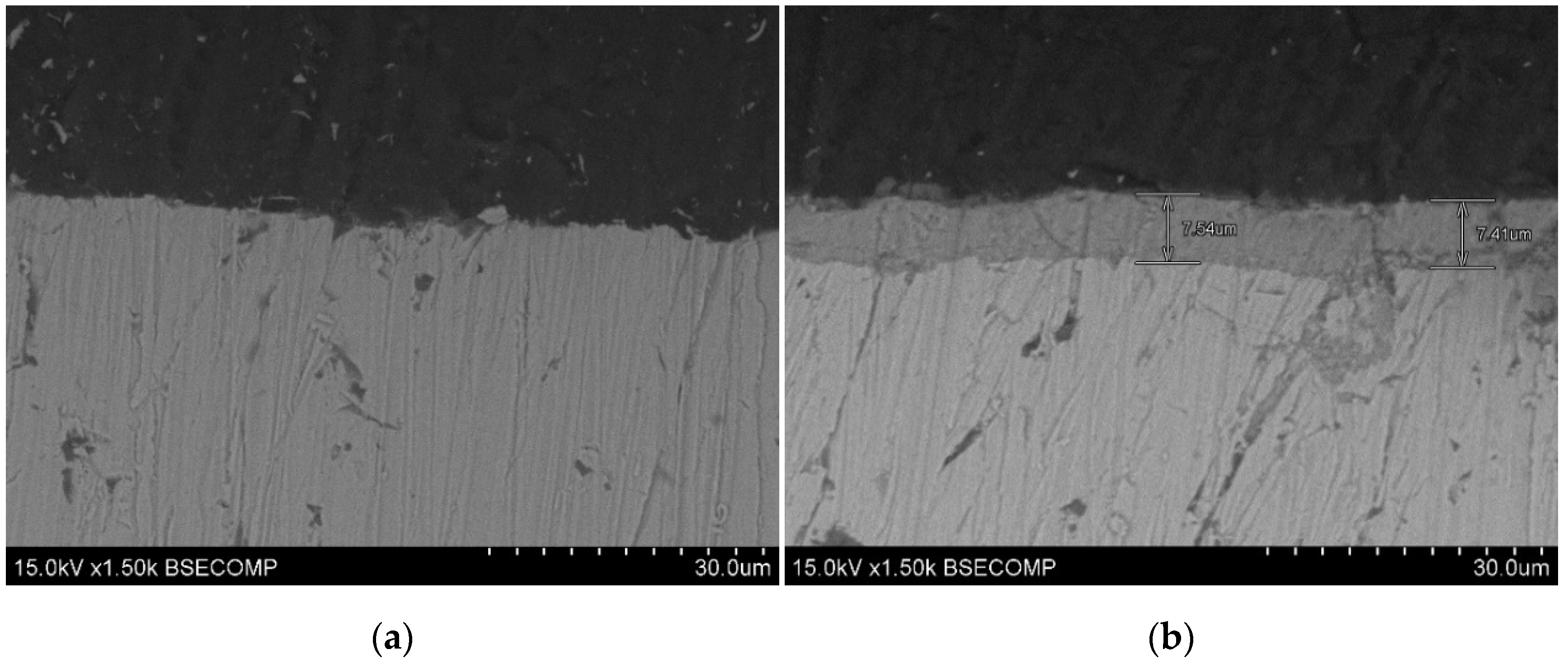
Figure 13 shows the cross-section images of uncoated steel before and after heat treatment cycles. Damage to the steel surface is apparent after 25 cycles and a layer of ~7.5 µm of Fe
3O
4 is present. It should be noted that the diffusion of oxygen could even be to higher depths from the surface [
27]. The Fe
3O
4 layer grows gradually with each heat treatment cycle. This can be clearly seen from the XRD data (
Figure 10). The XRD patterns of steel demonstrated only two peaks of iron at 44.7° and 65.1°. After 5 cycles of treatment, the formation of iron oxides was obtained. The ratio of highest intensity Fe (at 44.7°) and Fe
3O
4 (at 35.4°) peaks is 0.71. The peaks intensity ratio was reduced to 0.22 after 15 cycles, and finally, after 25 cycles, the iron peak disappears completely.
For the coated samples, the highest intensity peak was attributed to the bonding layer of NiCr at 2θ = 44.3°. By comparing it with the α-Al2O3 and γ-Al2O3 phase peaks at 2θ = 43.5° and 45.9°, respectively, it can be stated that the coating thickness remained similar. However, some changes were observed in the Al2O3 coating. It was estimated that the γ-Al2O3/NiCr peaks ratio slightly increased from 0.18 to 0.19 after 25 heat treatment cycles. Meanwhile, the α-Al2O3/NiCr peaks ratio increased from 0.21 to 0.35 after 25 cycles.
Meanwhile, in the Al2O3-13 wt.% TiO2 coating, the γ-Al2O3/NiCr ratio decreased from 0.08 to 0.07 after 25 cycles and the α-Al2O3/NiCr ratio decreased from 0.12 to 0.11. Based on these results, it can be stated that effectively forming protective Al2O3 coatings to prevent surface corrosion of steel in biomass firing plants and adding TiO2 chemical resistance can be further improved.
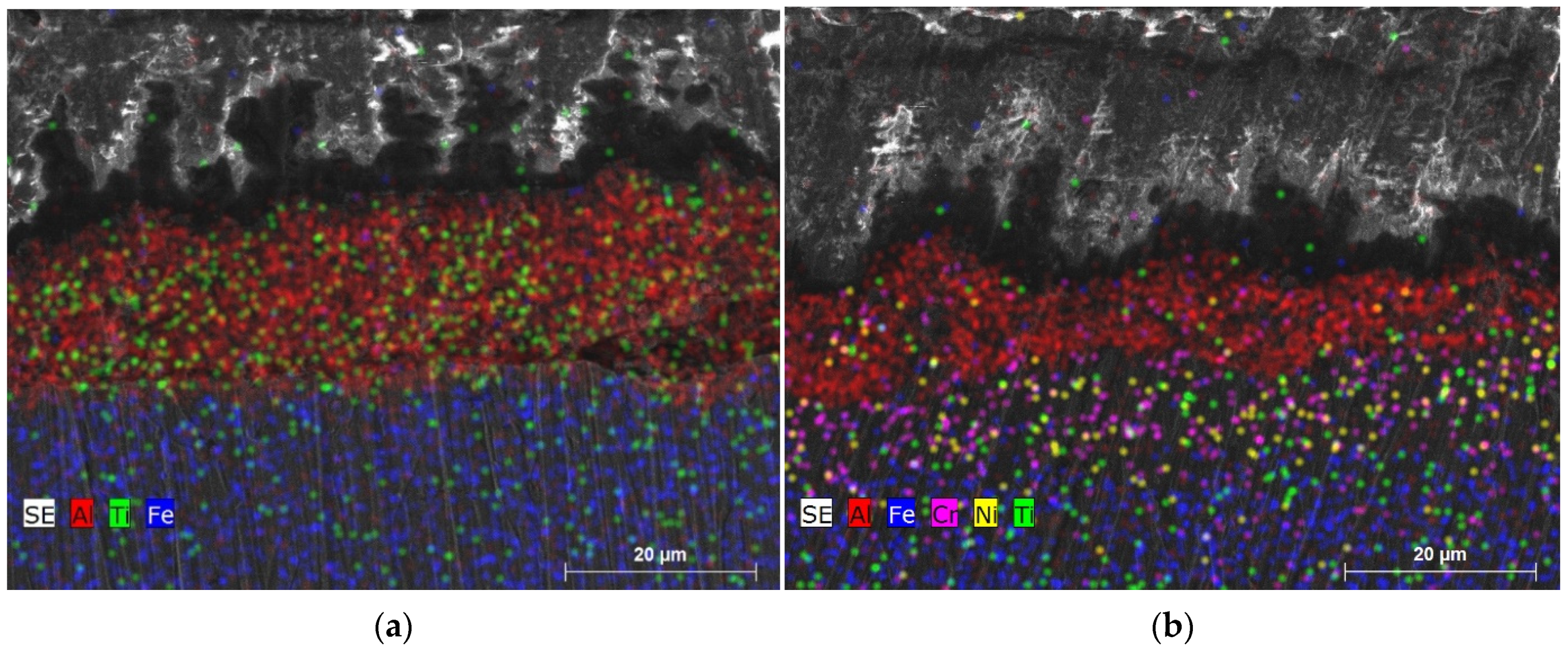
Figure 14 shows the cross-section mapping images of Al
2O
3-13 wt.% TiO
2 coating before and after 25 heat treatment cycles. The coating thickness remains similar before and after the treatment. However, a change of elemental distribution was observed. As-sprayed Al
2O
3-13 wt.% TiO
2 coating consists of aluminum and titanium distributed throughout the coating evenly, but after 25 cycles, aluminum concentrated on the surface of the coating titanium was widely distributed throughout the coating and bonding layer volume. Moreover, after the 25 heat treatment cycles, the clear boundary between the bonding layer (nickel and chromium) and deposited coating can be observed. After the treatment, the cross-section image of the coating (
Figure 14b) demonstrated that the Ni and Cr atoms do not diffuse into the coating or steel. It should be noted that no iron was found in the NiCr bonding layer after 25 cycles of treatment. T


 ,
, 


