Article

Efficiency of Application of (Mo, Al)N-Based Coatings with Inclusion of Ti, Zr or Cr during the Turning of Steel of Nickel-Based Alloy

1
Institute of Design and Technological Informatics of the Russian Academy of Sciences (IDTI RAS), 127055 Moscow, Russia
2
Materials Science and Metallurgy Shared Use Research and Development Center, National University of Science and Technology MISiS, 119049 Moscow, Russia
3
State Scientific Centre Keldysh Research Center, 125438 Moscow, Russia
*
Author to whom correspondence should be addressed.
Coatings 2021, 11(11), 1271; https://doi.org/10.3390/coatings11111271
Submission received: 27 September 2021 / Revised: 14 October 2021 / Accepted: 15 October 2021 / Published: 20 October 2021

Abstract

:
The article compares the properties of multilayer composite wear-resistant coatings of Zr–ZrN–(Zr, Mo, Al)N, Ti–TiN–(Ti, Mo, Al)N, and Cr–CrN–(Cr, Mo, Al)N. The investigation was focused on hardness, resistance to fracture during scratch tests, elemental composition, and structure of the coatings. Experiments were carried out to study the wear resistance of coated carbide tools during the turning of 1045 steel and of NiCr20TiAl heat-resistant nickel alloy. With the elemental compositions identical in the content of molybdenum (Mo) and aluminium (Al), identical thicknesses and nanolayer periods of λ, the coatings being studied demonstrated a noticeable difference in wear resistance. Both during the turning of steel and nickel-based alloy, the highest wear resistance was detected for tools with the Zr–ZrN–(Zr, Mo, Al)N coating (the tool life was 3–5 times higher than for uncoated tools). The good wear resistance of the Zr–ZrN–(Zr, Mo, Al)N coating may be related to the optimal combination of hardness and plasticity and the active formation of molybdenum oxide (MoO3) on the coating surface during the cutting, with good tribological and protective properties.

1. Introduction

The application of wear-resistant coatings made it possible to considerably increase the efficiency of the cutting process and prolong the tool life. However, the development of technologies for mechanical processing and the creation of high-performance equipment of a new generation requires an enhancement of the operational characteristics of metal-cutting tools. One of the ways to ensure such enhancement is to develop wear-resistance coatings with improved properties. In turn, such improvement of properties is possible due to the use of coatings with the optimal composition and architecture, as well as the development of progressive equipment and coating techniques. The important challenge during the development of new-generation coatings is a trend to an increase in the cutting speed, which leads to considerable growth of operating temperature [1,2,3]. An increase in temperatures up to 700 °C and above activates the diffusion and oxidation processes, and the material properties undergo a considerable change, including due to phase transformations [4,5,6]. Thus, in addition to the requirement to provide effective resistance to abrasive and adhesive-fatigue wear, traditional in the creation of coatings, there is a need to ensure high heat resistance and resistance to diffusion and oxidation wear [7,8,9]. The above requirements influence the selection of the coating composition, which should not only provide the maximum hardness and wear resistance but also retain those properties at high temperatures, with good barrier properties as for interdiffusion with the material being machined. In turn, the effective resistance to the oxidation process may be ensured both due to an increase in the temperature level at which the active formation of oxides begins and due to a formation of stable and continuous oxide films.
The coatings based on the (Mo, Al)N system meet well the above requirements, so their application in recent years has become more and more widespread [10,11,12,13]. With its high hardness (up to 38.4 GPa [12]), low value of compressive stresses [11], good resistance to temperature oxidation [11,13] and ability to form tribologically active films based on the Mo oxide of MoO3 and the Al oxide of Al2O3 [13], the (Mo, Al)N-based coating has good prospects for its use as a wear-resistant coating for cutting tools. At the same time, the conducted studies find that the performance properties of the (Mo, Al)N coating can be further improved through the introduction in its composition of elements, such as titanium (Ti), zirconium (Zr), or chromium (Cr) [14,15,16,17,18]. In particular, the (Ti, Al, Mo)N coating not only has a hardness of up to 40 GPa [19,20,21,22,23], but it is also characterised by perfect tribological properties and high wear resistance [14]. Another useful property of the (Ti, Al, Mo)N coating is its high resistance to cracking [21]. The above properties, in combination with the ability to form a protective tribological film of MoO3, allow the coating to provide a considerable increase in wear resistance at high temperatures as compared to the commercial coating of (Ti, Al)N [23]. The introduction of chromium in the composition of the (Mo, Al)N coating also increases its wear resistance [16]. The study of the (Cr, Al, Mo)N coating reveals the presence of two cubic phases of CrN and Mo2N [17,24,25,26,27]. The hardness of the (Cr, Al, Mo)N coating can reach 41.2 GPa [28]. With an increase in temperature, an oxide film of MoO3 is formed on the surface of the coating, which considerably decreases the coefficient of friction (COF) and leads to an improvement of wear resistance [26]. An increase in the performance properties of the (Mo, Al)N coating is also observed when zirconium is introduced in its composition [18]. Two cubic phases—ZrN and Mo2N—are formed in the coating. When the temperature grows above 500 °C, the COF of the coating begins to decrease, which can be related to the formation of oxide phases on its surface [18].
The studies carried out by Qi Yang [29] have found that the introduction of Mo in the compositions of the coatings of TiN, AlTiN, CrN, and ZrN can considerably improve their tribological properties and wear resistance. The studies reveal good performance properties during the turning of Mo-containing multilayer coatings, such as Cr, Mo–(Cr, Mo, Zr, Nb)N–(Cr, Mo, Zr, Nb, Al)N [30,31], and Cr, Mo–(Cr, Mo)N–(Cr, Mo, Al)N [31,32]. These coatings are characterised by high plasticity combined with perfect wear resistance [30], as well as good resistance to oxidation and interdiffusion [30,31,32]. The earlier studied coatings of (Cr, Al)N [33,34], (Ti, Al)N [33], and (Zr, Al)N [34] are characterised by good performance properties, allowing to achieve a considerably long tool life of a cutting tool during the turning. In particular, the (Zr, Al)N coating has a good combination of wear resistance and resistance to brittle fracture [34]. It can be predicted that the introduction of Mo into the composition of those coatings will provide an additional improvement of their properties.
Thus, the task of the investigation was to compare the performance properties of the coatings as follows: Zr–ZrN–(Zr, Mo, Al)N (hereinafter referred to as Coating M1), Ti–TiN–(Ti, Mo, Al)N (Coating M2), and Cr–CrN–(Cr, Mo, Al)N (Coating M3). The coatings being studied have a three-layer composition [35] with identical structural parameters. An adhesion layer with the thickness of 20–50 nm is located directly between the carbide substrate and the functional layers of the coating, followed by a transition layer of two-component nitrides (about 1 µm thick) and an outer wear-resistant layer (about 3 µm thick) based on four-component nitrides. The outer wear-resistant layer has a nanolayer architecture. The analysis of the available research results [11,12,13,14,16,18,20,22,25,26,28,29] reveals that the coatings with the content of about 40 at.% Mo and about 10 at.% Al can have the best properties. The content of Ti, Zr, or Cr should contain about 50 at.%, respectively. Such a percentage will provide the optimal combination of hardness and plasticity with high heat resistance, accompanied by the formation of a considerable amount of tribologically active oxides of MoO3 [13,19,26,30].
From a scientific and practical perspective, the task of the investigation was to find ways to increase the efficiency of machining materials, such as structural steels and nickel-based heat-resistant alloys. One of the possible ways to meet the challenge is to apply modifying coatings with nanolayer structure based on the (Me, Mo, Al)N system, where Me is Ti, Zr, or Cr.

2. Materials and Methods

The coatings were deposited using the filtered cathodic vacuum arc deposition (FCVAD) [35,36,37,38,39], with the experimental VIT-2 unit (VIT–IDTI RAS, Moscow, Russia) [40,41,42]. To deposit the coatings, the cathodes of Mo (99.98 at.%), Zr 99.97 at.% (for Coating M1), Ti 99.98 at.% (for Coating M2), or Cr 99.97 at.% (for Coating M3) were used. The cathodes were installed on arc evaporators with the pulsed magnetic field [43]. Due to the increased formation of macroparticles by Al, the cathode of Al 99.95 at.% was installed on a special evaporator with separation of up to 98% of the macroparticles [35,44]. The preparation of samples for the coating deposition included washing in a special solution with ultrasonic simulation, drying, and placing on a special toolset. To ensure the process was identical to actual manufacturing conditions, no additional treatment of the deposition surface (for example, polishing) was carried out. The toolset with samples was placed on a special turntable providing for planetary rotation during the deposition process. The turntable rotation rate was n = 0.7 rpm. The planetary rotation with the pre-set rate provided the formation of the nanolayer structure with optimal parameters [35,44]. Layers with the dominant content of Al, Mo, or Ti/Zr/Cr are being formed while the toolset with the samples passes through the corresponding plasma flow [6,35,44]. After the samples had been placed in the chamber and vacuum-processed, they were subjected to ion cleaning in gas (argon) plasma. After the cleaning of the samples, the coating deposition process was directly launched under the parameters as follows: arc current 160 A for the Al cathode, 75 A for the Ti and Zr cathodes, 125 A for the Mo cathode, and 73 A for the Cr cathode. During the coating deposition process, the pressure of the reaction gas (nitrogen) in the chamber was 0.42 Pa. The substrate bias voltage was −50 DC. During the process of coating deposition, sources of infrared radiation were used to heat the surfaces of the samples to a temperature of 600–650 °C. The deposition of an adhesion layer lasted 3 min, a transition layer—15 min, and a wear-resistant layer—45 min. The total thickness of all the considered coatings was 4 µm.
Carbide (WC + 15% TiC + 6% Co) cutting inserts of SNUN ISO 1832:2012 [45] were used as a substrate. To measure the hardness of the samples, the micro-indentometer hardness tester (CSM Instruments, Needham, MA, USA) was used, with the Oliver-Pharr method [46], the load was 10 mN. The scratch-test resistance was determined in accordance with ASTMC1624-05 [47] on a Nanovea M1 scratch-test tester (Micro Scratch, Nanovea, Irvine, CA, USA). The critical load LC2 was determined by the acoustic emission method. This value characterises the beginning of complete destruction of the coating.
A scanning electron microscope (SEM) FEI Quanta 600 FEG (Materials & Structural Analysis Division, Hillsboro, OR, USA) was involved in conducting the microstructural studies of the samples of carbide substrates with coatings. A high-resolution transmission electron microscope (TEM) JEM 2100, manufactured by JEOL Company, Tokyo, Japan, was used to carry out the nanostructure studies. The coatings’ elemental compositions were analysed using a TEM with the EDX system INCA Energy (OXFORD Instruments, Abingdon, Oxfordshire, UK) and the scanning transmission electron microscopy (STEM) technique. The TEM samples (lamellas) were prepared with the use of a Strata focused ion beam (FIB) 205 (FEI, Hillsboro, OR, USA).
The influence of the studied coatings on wear resistance of cutting tools during the turning of 1045 steel (P machinability group under ISO 513:2012 [48]) and heat-resistant NiCr20TiAl nickel-based alloy (S machinability group under ISO 513:2012 [48]) was studied. The chemical compositions of 1045 steel and NiCr20TiAl nickel-based alloy are shown in Table 1 and Table 2, respectively.
To test the cutting properties of the tools with the coatings being studied, a CU 500 MRD (ZMM-BULGARIA HOLDING, Sofia, Bulgaria) lathe was used. During the testing, 1045 steel (HB 200) and heat-resistant nickel-based alloy of WNr NiCr20TiAl (EN 10090:1998, HRC 32) were subjected to the longitudinal turning. Cutting tools were represented by cutters with cemented carbide SNUN ISO 1832:2012 inserts [45]. The cutting geometry was as follows: γ = −7°, α = 7°, K = 45°, λ = 0°, and R = 0.8 mm. During the turning of 1045 steel, the following cutting modes were used: f = 0.2 mm/rev; ap = 1.0 mm; and vc = 400 m/min; during the turning of WNrNiCr20TiAl nickel-based alloy, the cutting modes were as follows: f = 0.11 mm/rev; ap = 0.5 mm; and vc = 90 m/min. The ultimate flank wear VBmax = 0.35 mm was assumed as a wear criterion for all cutting conditions. Each experiment was repeated three times, and the curve depicts the average value and the margin of error. The wear criterion VBmax is considered reached if the value of VBmax was exceeded in at least one experiment.

3. Results and Discussion

3.1. Study of Mechanical Properties, Structure, and Composition of Coatings

Table 3 presents the data on the study of the elemental composition, hardness, and critical load fracture LC2. The content of nitrogen in the coating composition was 47–49 at.% (data obtained during previous studies of coatings of a similar composition by the X-ray photoelectron spectroscopy (XPS) method). For a convenient comparison, Table 1 exhibits the data on the elemental composition of the coating, excluding nitrogen.
The measured content of Mo was 34–43 at.%, and the content of Al–8–15 at.%. The content of Zr/Ti/Cr was 46–55 at.%. The difference in the content of elements in the three studied coatings is associated with their nanolayer structure, in which the content of elements varies noticeably along with the thickness of each nanolayer [30,31,32]. The values exhibited in Table 1 are the average values within the thickness of the wear-resistant layer. The coatings have fairly close values of hardness, from 26.60 ± 1.30 GPa for Coating M3 to 30.70 ± 1.20 for Coating M2. The values of the critical fracture load LC2 are also considerably close and range from 36 to over 40 N. Such values of LC2 indicate sufficient adhesion to the substrate, especially taking into account the fact that the substrate is a commercially available carbide insert not subjected to additional treatment (for example, polishing).
The studies of the nanolayer structure of the coatings find (Figure 1) that they have very close values of the nanolayer period λ: 40, 43, and 48 nm for Coatings M1, M2, and M3, respectively.
Thus, the coatings being studied have the compositions identical in terms of the content of Mo and Al, similar mechanical properties, measured at room temperature, and similar nanolayer structure. It should be noted that the real cutting conditions have a decisive influence on the properties of the tool material in general and the coating in particular. During the cutting, especially at high cutting speeds, the temperature can grow to 1000 °C and above, which results in the change in the tool material properties and active action of the diffusion and oxidation processes.

3.2. Cutting Properties and Wear Patterns on Coated Tools during the Turning of 1045 Steel

After 18 min of turning, a tool with Coating M1 reached the wear criterion VBmax = 0.35 mm (Figure 2). The tool life for an uncoated tool is 6 min, for a tool with Coating M3, it is 10 min, and for a tool with Coating M2, it is 14 min. Despite the considerably close structure and mechanical properties, the tools with Coatings M1–M3 demonstrated significant differences in the wear dynamics. All three coatings being studied provide an increase in the tool life compared to uncoated tools (from 70 to 300%). The best result is provided by Coating M1.
We compare the wear patterns on the tools with Coatings M1–M3 (Figure 3). It should be noted that the coatings being studied demonstrate even more difference in the rake wear, in particular, the depth of wear crater, than in the flank wear. After 18 min of cutting, only an insignificant wear crater with the depth of KT = 9 µm and the width of KB = 472 µm (Figure 3a) was formed on the sample with Coating M1, whereas for the sample with Coating M2, KT = 34 µm and KB = 565 µm, and for the sample with Coating M3, KT = 57 µm and KB = 765 µm. Thus, the rake wear rate for the sample with Coating M1 is considerably lower than that for the samples with Coatings M2 and M3.
Notch wear is another significant wear factor affecting the overall wear resistance of metal-cutting tools. Notch wear is formed as a result of the strong adhesive interaction between the chip flow and the rake face of the tool [49]. The notch wear rate is significantly influenced by factors such as transverse stress, temperature in the cutting zone, and temperature-related oxidation processes [50,51,52,53]. Notch wear significantly affects the roughness of the machined surface, and some researchers suggest that this influence is even more significant than the effect of the rake or flank wear [54]. In turn, there are data that the notch wear rate, such as the flank wear rate, is primarily affected by the hardness of the coating [55]. There are two areas of notch wear that are also present on the inserts being studied on the minor (Figure 4a–c) and major (Figure 4d–f) flank faces. The insert with Coating M1 has the least intense notch wear on both considered areas (Figure 4a,d). The most intense wear on the minor flank face is observed on the sample with Coating M2 (Figure 4b), whereas on the sample with Coating M3, the wear in the considered area is less intense (Figure 4c). For the samples with Coatings M2 and M3 (Figure 4c,f), the notch wear rate on the major flank face is almost the same. Thus, the tool with Coating M1 has the highest wear resistance of the considered samples, not only in terms of the flank wear and intensity of crater formation on the rake face but also in terms of the notch wear rate.
We consider the distribution of elements on the rake faces of the considered samples after 18 min of cutting. Figure 5 depicts the localisation of the areas of distribution maps.
The analysis of the research results with regard to the distribution of the key elements on the rake faces of the worn inserts with the coatings being studied (Figure 6) distinguishes the following features. Although in all the coatings being studied the content of Mo is identical (about 40 at.%), only Coating M1 demonstrates an increased concentration of Mo in the considered area of M1-A. In combination with the high oxygen content in the considered area (see Figure 7), this may mean the presence of a noticeable amount of Mo oxide (MoO3) in the area being studied. No similar concentration of Mo is observed in other coated samples being studied, but the sample with Coating M2 has an increased concentration of Ti in the considered area. In combination with the increased concentration of oxygen in a similar area on the sample with Coating M2 (see Figure 7), it can be concluded that the formation of Ti oxide takes place. The sample with Coating M3 does not exhibit any area with a high concentration of Cr or any region with high oxygen content, from which it can be concluded that the oxide formation for the sample with Coating M3 is weak. While it is possible to assume the formation of noticeable amounts of oxides for both Coatings M1 and M2, the oxides differ significantly in their properties and their influence on the cutting process. The Ti oxide is a considerably soft and porous substance that does not exhibit noticeable tribological properties [56,57], and Mo oxide of MoO3, on the contrary, is a fairly solid and dense substance with excellent tribological properties [58,59]. Based on the oxygen content in Area A for Coatings M1 and M2, it can be assumed that the MoO3 film formed on Coating M1 is characterised by good integrity and can have a noticeable effect on the cutting conditions. The Ti oxide formed on the surface of Coating M2 is present in the form of isolated islands and is unlikely to significantly affect the cutting process. Although the Mo content in the coatings being studied is identical, the active formation of Mo oxide of MoO3 can be assumed only in Coating M1. The described phenomenon may be associated with the influence of the total elemental composition of the coating at the temperature, which triggers the active oxide formation, as noted in several sources [60,61].
For a better understanding of the wear mechanisms for the considered samples, we consider the pattern of cracking in the nanolayer structure of the coatings (Figure 8, Figure 9 and Figure 10). Figure 8 depicts a cross-section view of a carbide insert with Coating M1, passing through the centre of the wear crater. The structure of Coating M1 demonstrates the formation of longitudinal cracks and delamination between the nanolayers. In this case, the mechanism of considerably plastic cracking takes place, with the formation of bond bridges between the nanolayers (see Area A in Figure 8). The described cracking mechanism is typical for ZrN-based coatings [6,42,49], and it is considered favourable in terms of the working efficiency of the coated tools.
Figure 9 exhibits the pattern of cracking in Coating M2 on a cross-section, passing through the centre of the wear crater (Figure 9). In this case, the prevailing cracking mechanism is delamination between the coating nanolayers. The described cracking mechanism may be associated both with the relatively low strength of cohesive bonds between nanolayers and with the presence of a high level of compressive stresses in the coating structure [6,42,49].
Coating M3 demonstrates intense cracking, with both longitudinal and transverse cracks, cutting through the coating structure (Figure 10). The cracking mechanism detected for Coating M3 is the least favourable one in terms of the tool life, as due to active cracking, the brittle fracture of the coating can significantly decrease the total wear resistance of the coating and the tool life.

3.3. Cutting Properties and Wear Patterns on Coated Tools during the Turning of Heat-Resistant WNr NiCr20TiAl Nickel-Based Alloy

The heat-resistant nickel-based alloy of WNr NiCr20TiAl is used for the manufacture of hot-rolled bars, cold-rolled strips, discs, rings, turbine blades, and other parts operated at temperatures up to +750 °C, spring wire for the production of cylindrical compression and tension springs with operating temperatures from −253 °C to +500 °C in various environments (air, seawater vapour up to +200 °C, vacuum) and used in turbine seals, shutoff valves, heaters, and reactor control devices. The nickel-based alloy of WNr NiCr20TiAl is characterised by good technological properties and is considerably difficult to cut [62,63,64,65]. Figure 11 depicts the relationship between the flank wear VB and the cutting time during the turning of the WNr NiCr20TiAl nickel-based alloy. An uncoated tool has a low service life under the given machining conditions. Out of the five considered inserts, three demonstrated catastrophic wear and complete failure after 10 min of cutting, whereas the ultimate value of the flank wear VBmax = 0.35 mm was reached after 5 min of cutting. The wear rates for tools with Coatings M1–M3 differ to a lesser extent than during the turning of 1045 steel. Under the given conditions, the highest wear rate was detected for the tool with Coating M2 (VBmax was reached after 10 min of cutting), the tool with Coating M3 reached VBmax after 12 min of cutting, and the tool with Coating M1 remained operational during 15 min of cutting (which is three times higher compared to the uncoated tool). Thus, under the given conditions, the highest wear resistance was demonstrated by the tool with Coating M1.
Figure 12 depicts the pattern of wear on the rake faces of the tools with Coatings M1–M3 after 15 min of turning of WNr NiCr20TiAl nickel-based alloy. In contrast to the turning conditions for 1045 steel, no wear crater is formed under the given conditions of cutting, but a considerably flat area of wear is formed. In terms of the rake wear, the highest wear resistance was detected for the tool with Coating M1 (KB = 670 mm). The tools with Coatings M2 and M3 demonstrated fairly similar wear rates (KB = 800 and 850 mm, respectively). The greatest distortion of the shape of the cutting edge was detected for the tool with Coating M2, which also had the lowest resistance to the rake wear under the given conditions of cutting.
The analysis of the distribution of elements on the wear area on the rake faces of the tools with the coatings being studied (Figure 13) reveals the presence of an adherent of the material being machined with high Ni content, the regions of the uncoated carbide substrate with high tungsten content and the regions with the retained coating with high Mo content. The analysis of the oxygen distribution in the area under consideration does not detect the oxygen formation zone in the coatings (Figure 13d–f). The regions with high oxygen content are only related to the adherent of the material being machined. Thus, under the given conditions of cutting, we detect no noticeable signs of the influence of the oxidation processes on the wear of cutting tools.

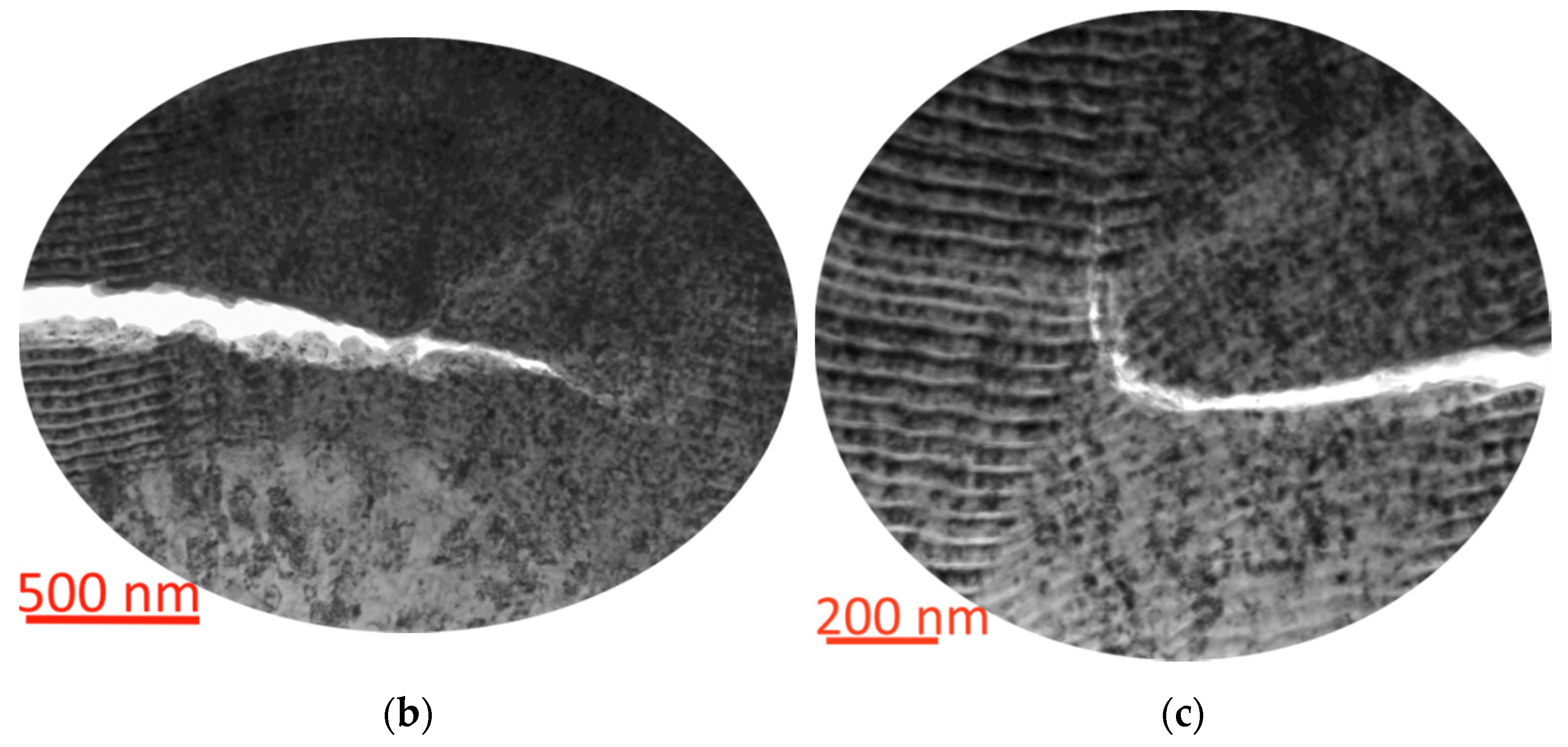
3.4. Analysis of Structural Changes in Worn Coatings

We analyse the changes in the nanostructure of the considered coatings taking place during operation. Earlier, it was found [32,66,67] that plastic deformation occurs in the coating nanolayers under the influence of the cutting conditions (including the action of cutting force and temperature). During the turning of 1045 steel, the plastic deformation zones, characterised by displacement of the nanolayers, arise in the structure of Coating M1 (Figure 14a). The typical wear processes take place in the area of close plastic contact between the worm surface of the coating and the moving layer of the material being cut. In particular, the worn surface of the coating forms steps (protrusions) at the points where the nanolayers emerge (Figure 14b). The above steps (protrusions) can influence the contact between the coating and the layer of the material being cut.
The structure of Coating M2 also contains the plastic deformation zones formed under the influence of the cutting conditions (Figure 15c). The considerably active cracking process takes place in the coating, which can also be seen in the SEM image (Figure 9). Cracks can grow both along the boundary of the nanolayers (Figure 15b) and through cutting the nanolayers (Figure 15c). Coating M2 demonstrates no formation of plastic bond bridges between the nanolayers typical for Coating M1 (see Figure 8). That fact may indicate lower plasticity of Coating M2, which is, in principle, typical for the (Ti, Al)N–based coating [49]. The outer surface of the coating, along which the flow of the cut material moves, contains some irregularities (protrusions and depressions) that can affect the movement of the material flow and its interaction with the coating (Figure 15a).
The pattern of plastic deformations in the structure of Coating M3 has noticeable differences from Coatings M1 and M2. While at a small bending angle, the nanolayer structure retains its plasticity, and no fracture occurs (Figure 16a), then at large bending angles, the coating nanolayers begin to fracture (Figure 16b). In the area of such fracture, the probability of crack formation and rapid brittle fracture of the coating increases sharply.
Thus, Coatings M1 and M2 demonstrate generally similar cracking mechanisms, but Coating M1 has more pronounced plastic properties, which are manifested, in particular, in the ability to form bond bridges between nanolayers. Coating M3 is much less plastic and is highly prone to cracking and brittle fracture during the cutting process.

4. Discussion

Thus, all the considered coating provided an increase in the tool life compared to uncoated tools (from 70 to 300%) during the tuning of 1045 steel at vc = 400 m/min. The coating of Zr–ZrN–(Zr, Mo, Al)N (Coating M1) provides a threefold increase in wear resistance. During the turning of NiCr20TiAl nickel-based alloy at vc = 90 m/min, it hardly makes sense to use an uncoated tool because of the high wear rate and possible failures. The tools with the considered coatings demonstrate the tool life of 10–15 min with the wear rate lower compared to the wear rate detected under similar conditions for carbide tools with the experimental and commercial coatings of Al2O3/TiN [62,63,64,65], TiN, Ti/TiN/(Ti,Cr,Al)N [68], and TiN/TiCN/Al2O3/ZrCN [69,70]. The nickel-based alloy was machined under the modes close to critical [62,63]. Thus, the application of the considered coatings, especially the coating of Zr–ZrN–(Zr, Mo, Al)N (Coating M1), not only increases the tool life up to three times but also ensures the efficient machining of workpieces made of NiCr20TiAl nickel-based alloy in the cutting conditions, in which the use of uncoated tools is not possible. The high-performance properties of Coating M1 may be associated with a combination of properties, such as considerably high hardness (and, accordingly, resistance to abrasive wear), sufficient ductility to inhibit cracking, and ability to form tribologically active oxides of MoO3, which have a positive effect on the cutting conditions. Due to the combination of the above properties, Coating M1 can be efficiently applied during the turning of structural steel (P machinability group) and also during the turning of nickel-based alloy (S machinability group), which is considerably harder to cut.

5. Conclusions

The investigation was focused on the properties of three coatings as follows: Zr–ZrN–(Zr, Mo, Al)N (Coating M1), Ti–TiN–(Ti, Mo, Al)N (Coating M2), and Cr–CrN–(Cr, Mo, Al)N (Coating M3).
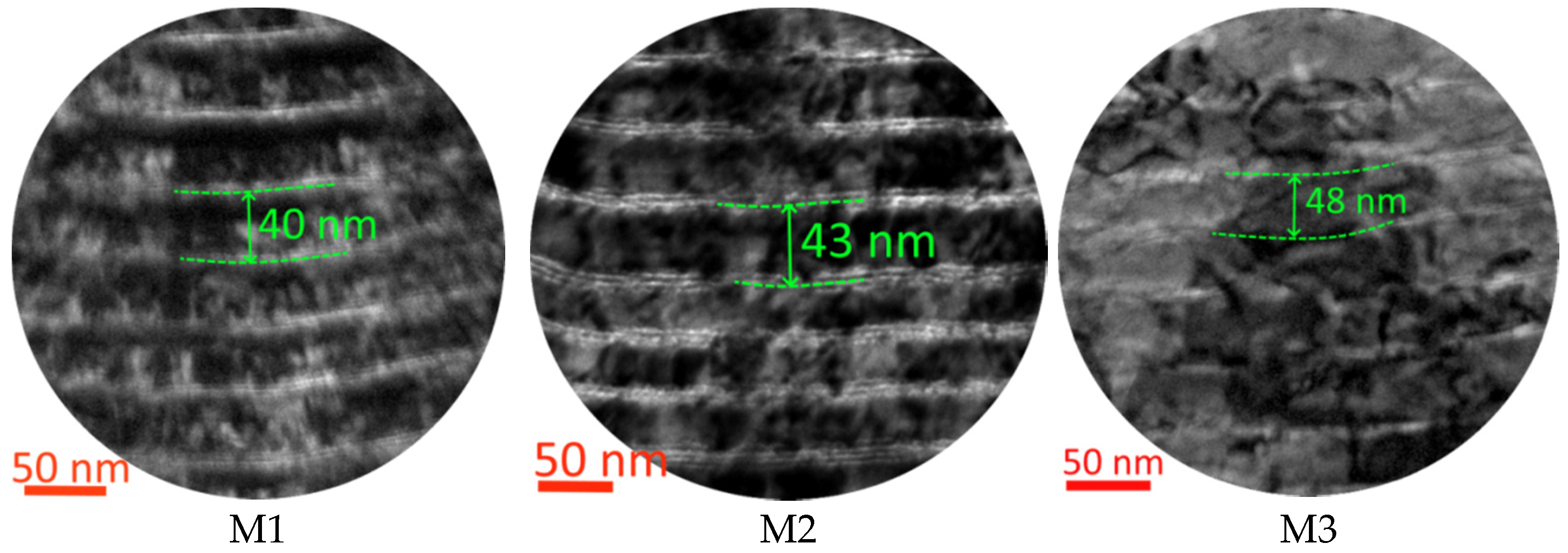
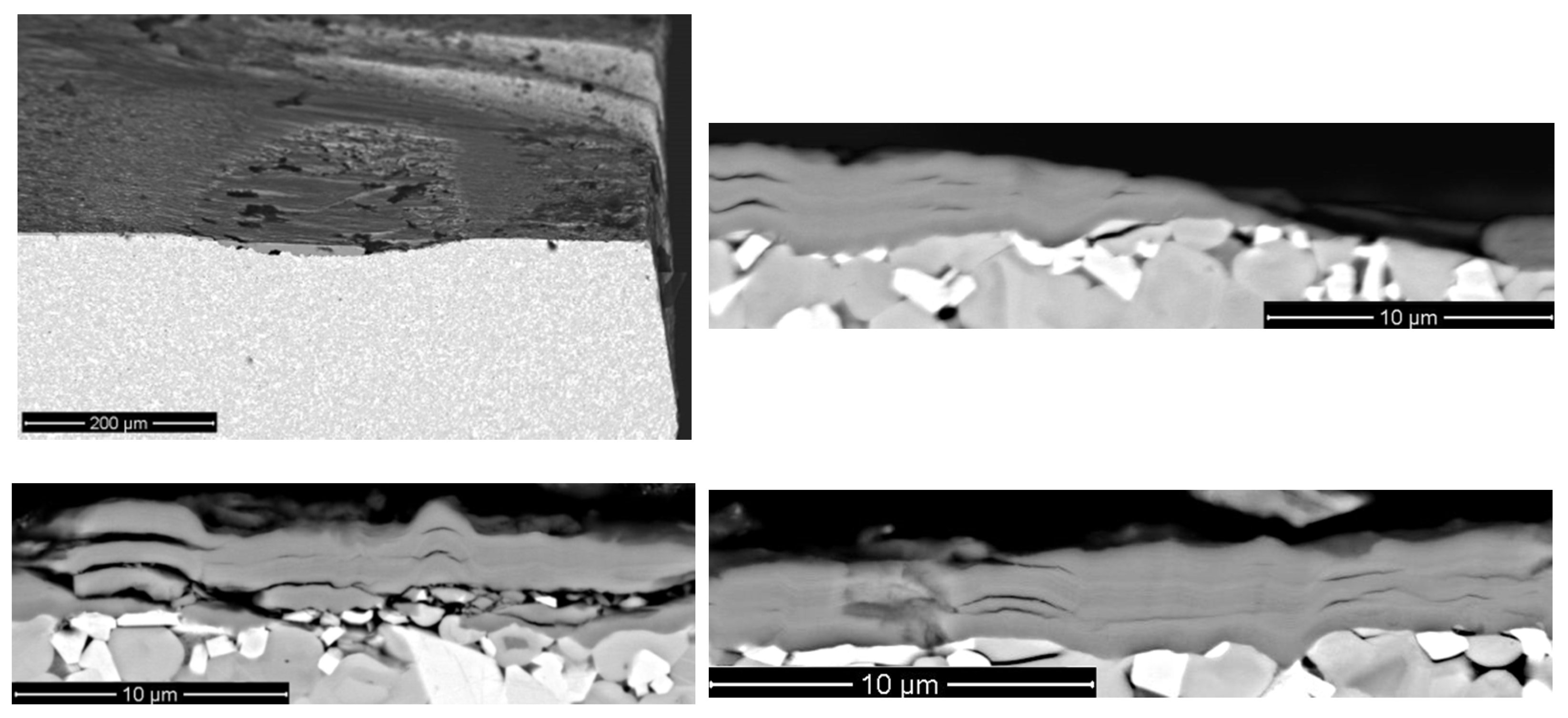
  • The coatings studied are very close in terms of their compositions, structures, and basic mechanical properties. The studies of the elemental compositions found that the considered coatings are identical with regard to the content of Mo, Al, and Zr/Ti/Cr. With the equal total thickness of about 4 µm and the thickness of a wear-resistant layer of about 3 µm, the coatings are also characterised by almost equal values of the nanolayer period. The experiments found considerably close values of hardness and critical load fracture LC2 for the considered coatings. At the same time, the coatings studied demonstrated a significant difference in wear resistance during the turning.
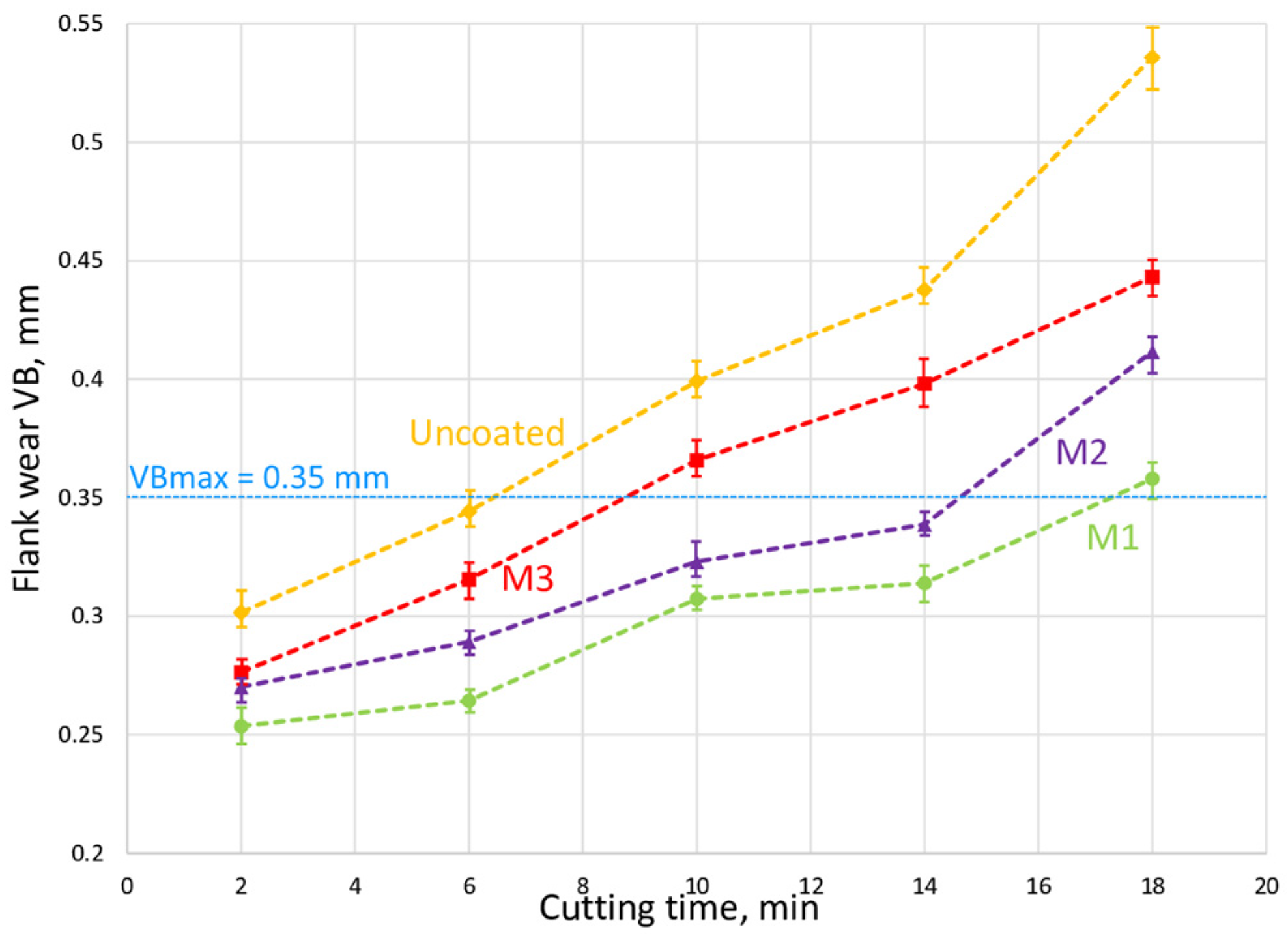
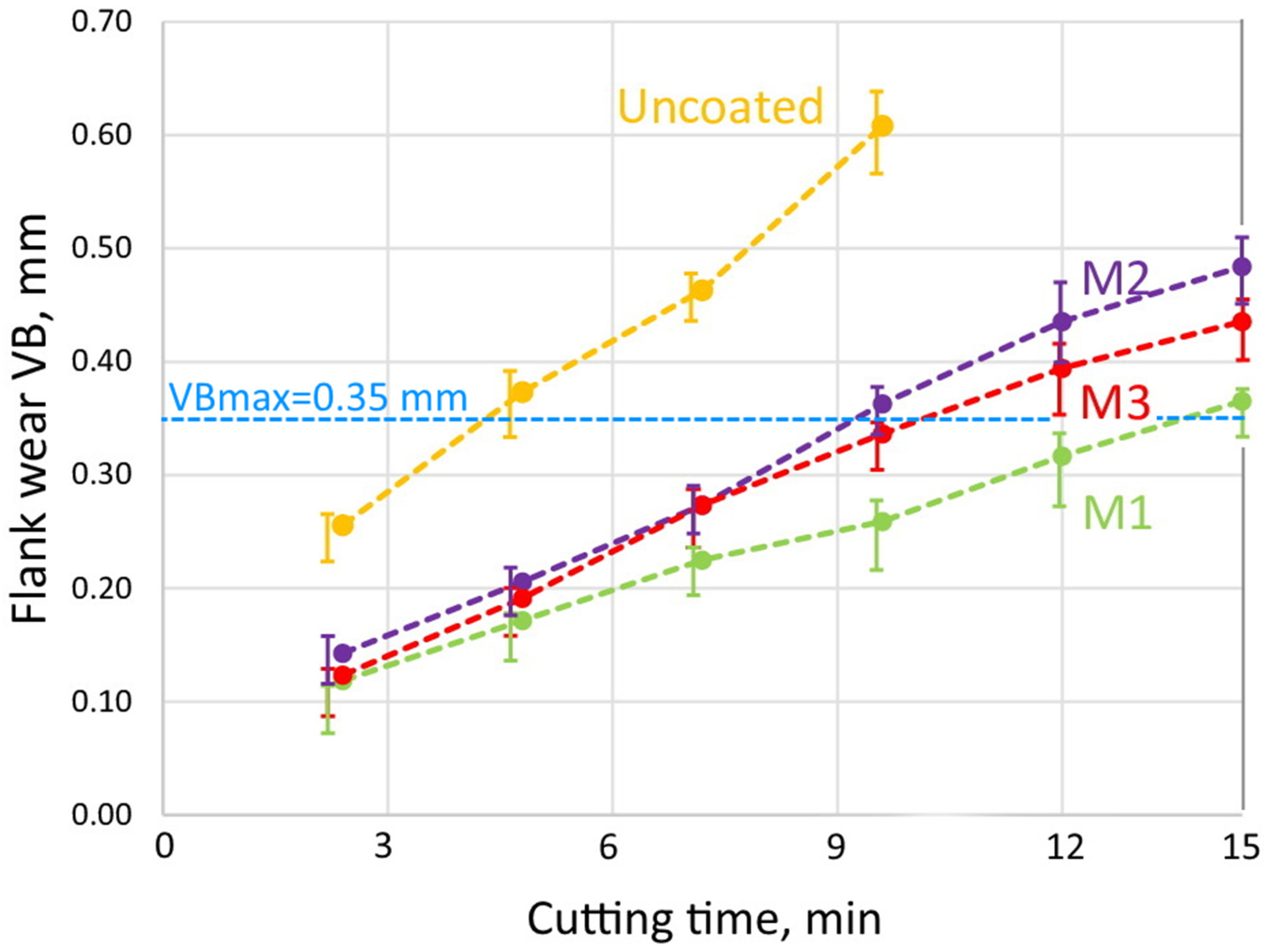
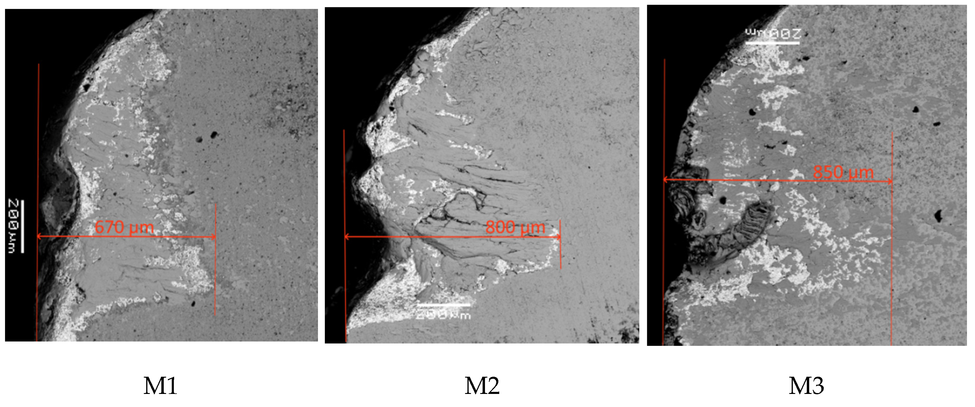
  • Taking into account that the tool life of the uncoated tool during the turning of 1045 steel is 6 min, the tool with Coating M3 demonstrated the tool life of 10 min, the tool with Coating M2 demonstrated 14 min, and the tool with Coating M3 demonstrated 18 min. During the turning of the WNr NiCr20TiAl heat-resistant nickel-based alloy, the highest wear rate was detected for the tool with Coating M2, while the tool with Coating M3 reached VBmax after 12 min of cutting, and the tool with Coating M1 remained operational during 15 min of cutting (three times longer compared to uncoated tools). Thus, the tool with Coating M1 demonstrated the highest wear resistance both during the turning of steel and during the turning of heat-resistant nickel-based alloy.
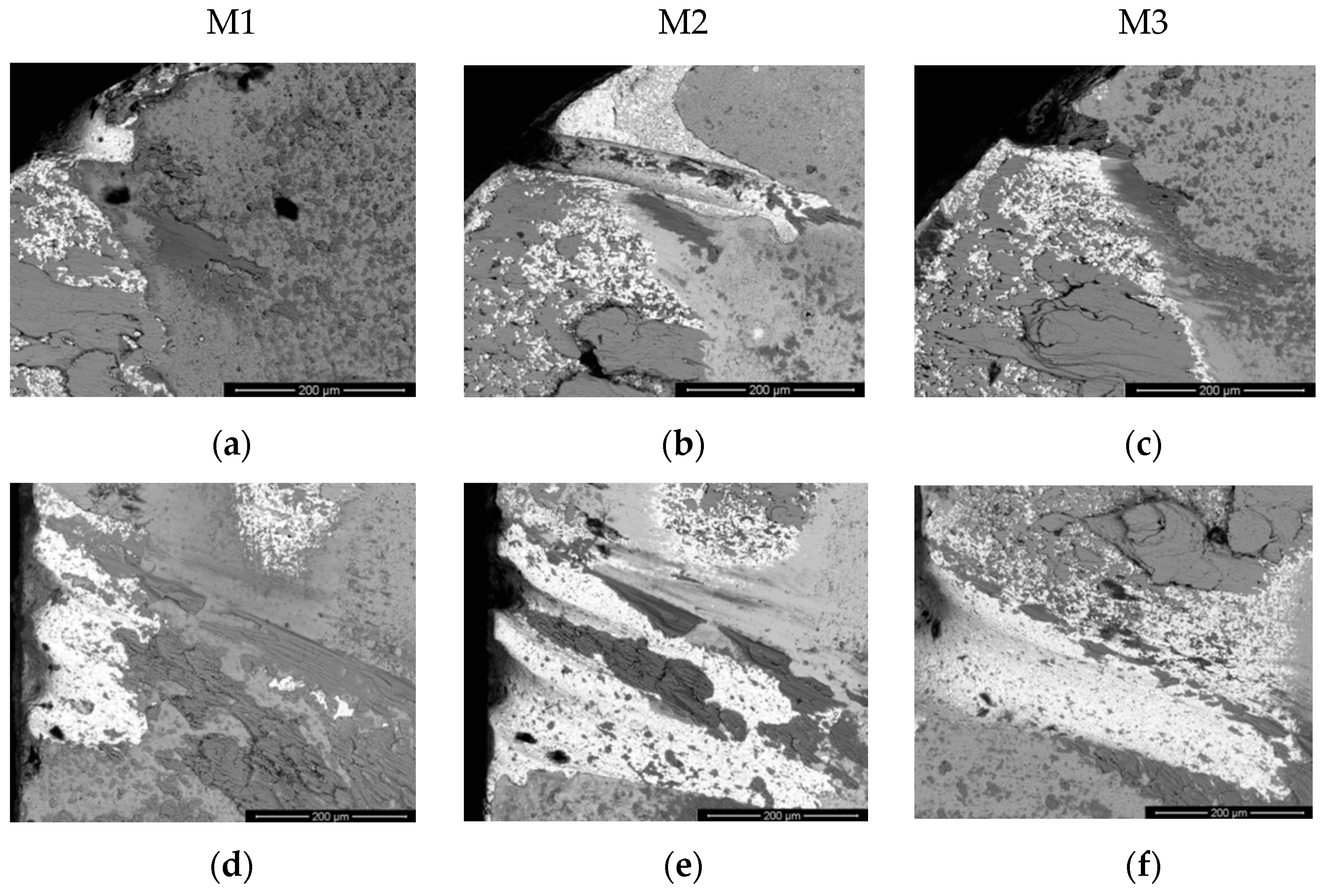
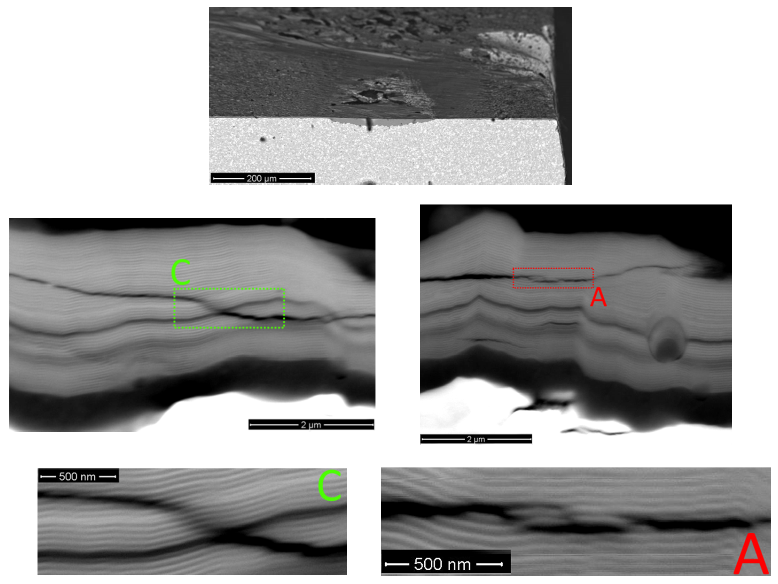
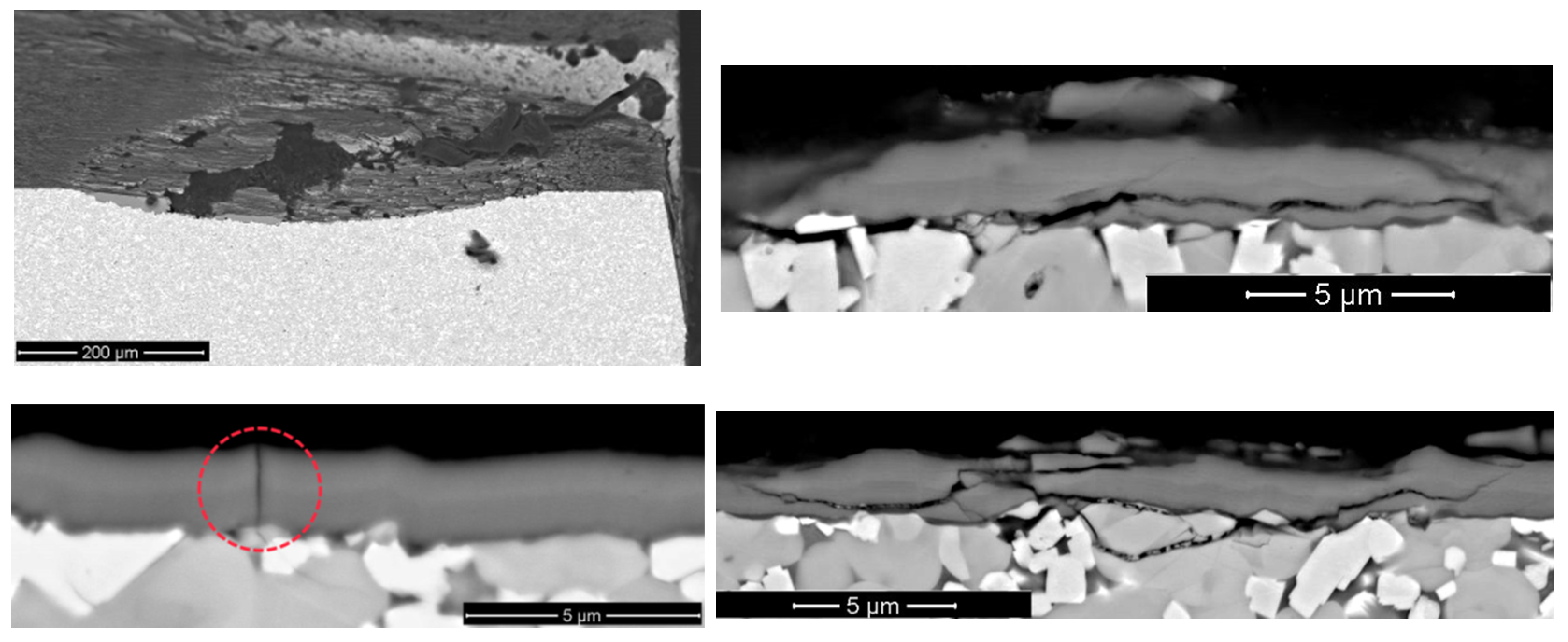
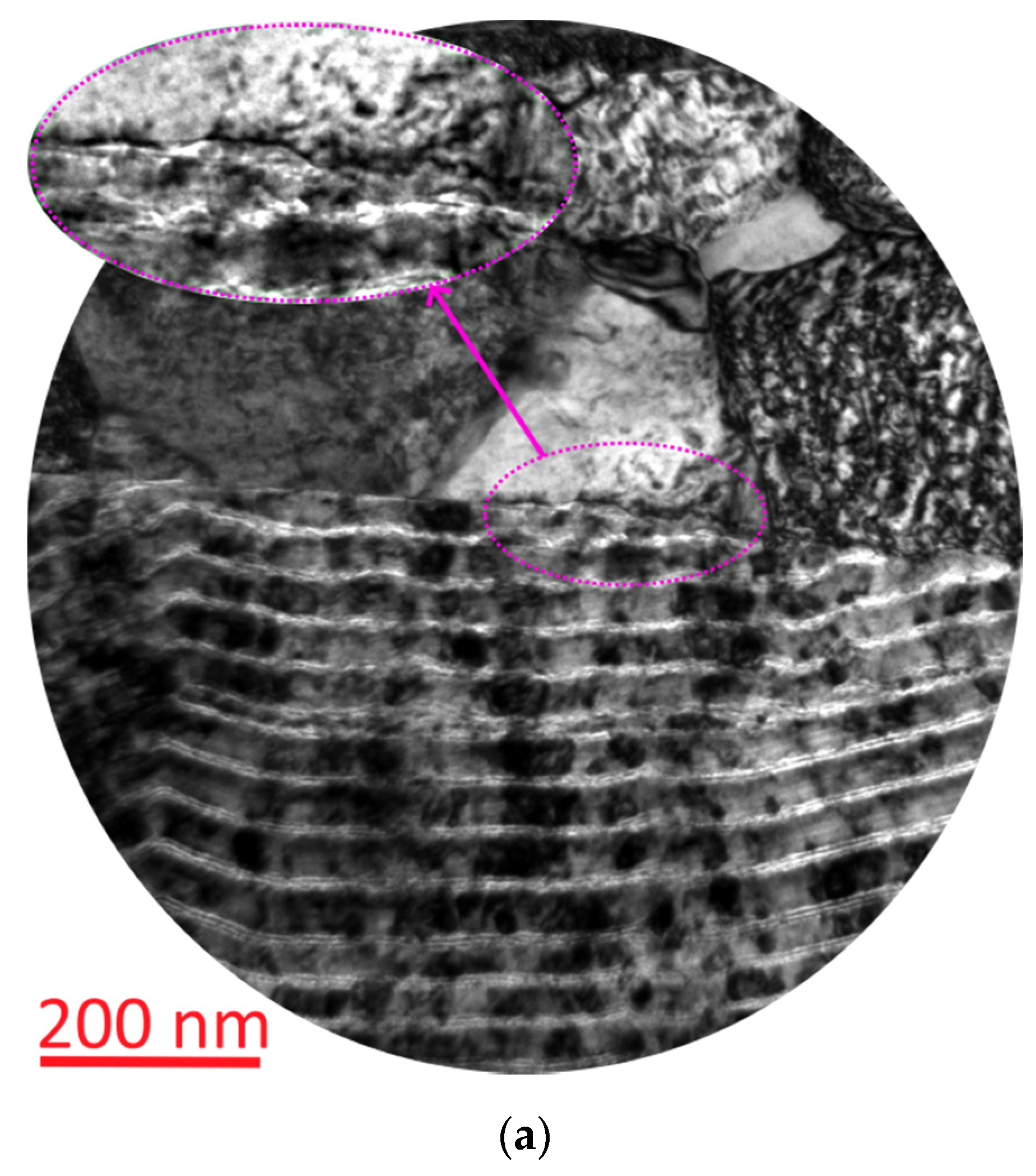
  • The investigation of the cracking mechanism found the highest crack resistance of Coating M1 and the greatest tendency to brittle fracture of Coating M3.
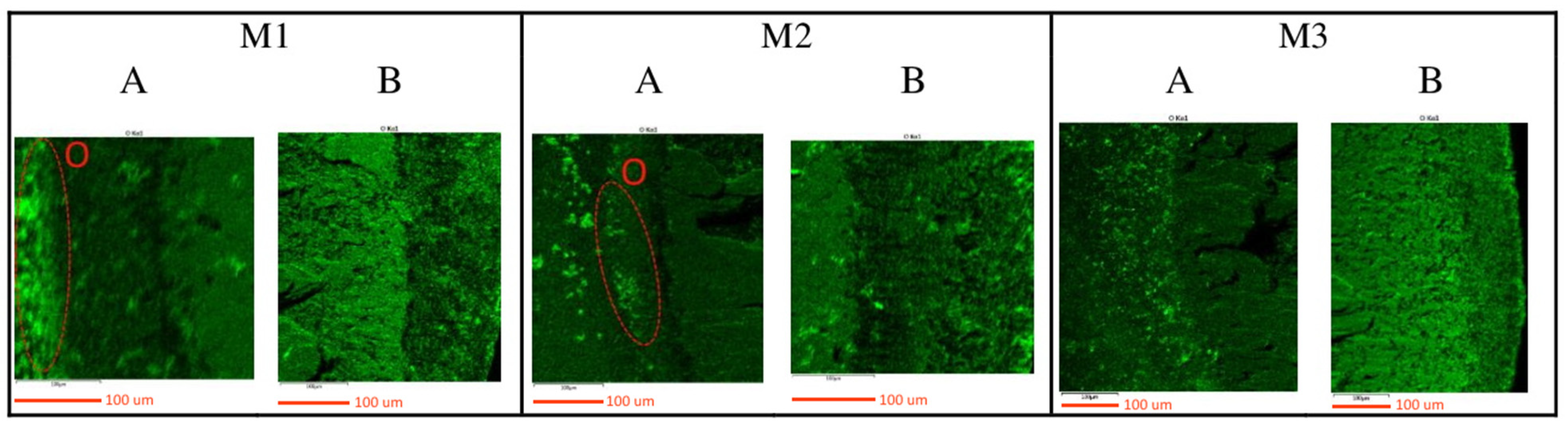
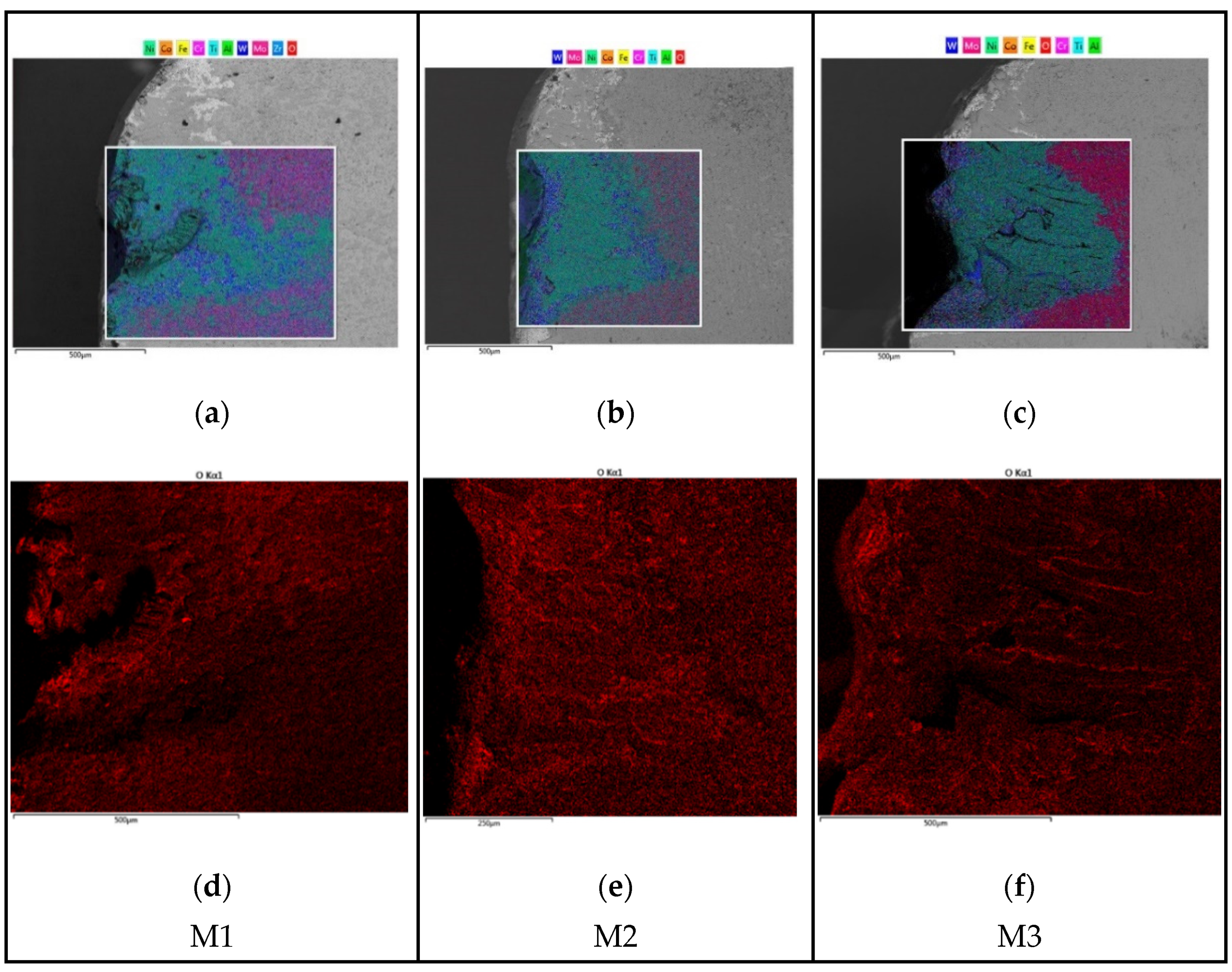
  • Given that the coatings studied are characterised by the identical content of Mo, the active formation of tribologically active Mo oxide of MoO3 during the cutting can be assumed only in Coating M1. The formation of Ti oxide, which does not possess protective and tribological properties, is possible in Coating M2.
Thus, Coating Zr–ZrN–(Zr, Mo, Al)N (M1) has the highest wear resistance among the coatings in the study, which can be explained by the combination of sufficient hardness, good resistance to cracking and brittle fracture, and the ability to actively form Mo oxide of MoO3. The coating has good prospective applications not only during the turning of structural steels but also during the machining of nickel-based heat-resistant alloys, including at high cutting speeds.

Author Contributions

Conceptualisation, A.V.; methodology, A.V. and F.M.; validation, A.M., M.M. and A.T.; investigation, F.M., N.A. and N.S.; resources, I.A.; data curation, N.S.; writing—original draft preparation, A.V.; project administration, I.A.; funding acquisition, I.A. All authors have read and agreed to the published version of the manuscript.

Funding

Results of this work were obtained as part of the work under the Agreement on the provision of subsidies dated 14 December 2020 No. 075-11-2020-032 (state contract identifier—000000S207520RNU0002) with the Ministry of Science and Higher Education of the Russian Federation.

Institutional Review Board Statement

Not applicable.

Informed Consent Statement

Not applicable.

Data Availability Statement

Data available on request due to restrictions privacy or ethical.

Conflicts of Interest

The authors declare no conflict of interest.

References

  1. Salomon, C.J. Process for Machining Metals of Similar Acting Materials When Being Worked by Cutting Tools. German Patent Nr. 523594, 27 April 1931. [Google Scholar]
  2. Boothroyd, G.; Knight, W.A. Fundamentals of Machining and Machine Tools; CRC Press: Boca Raton, FL, USA, 2006. [Google Scholar]
  3. Kuzin, V.V.; Grigoriev, S.N.; Volosova, M.A. The role of the thermal factor in the wear mechanism of ceramic tools: Part 1. Macrolevel. J. Frict. Wear 2014, 35, 505–510. [Google Scholar] [CrossRef]
  4. Loladze, T.N. Of the theory of diffusion wear. CIRP Ann.-Manuf. Technol. 1981, 30, 71–76. [Google Scholar] [CrossRef]
  5. Loladze, T.N. Nature of brittle failure of cutting tool. CIRP Ann.-Manuf. Technol. 1975, 24, 13–16. [Google Scholar]
  6. Vereschaka, A.; Tabakov, V.; Grigoriev, S.; Sitnikov, N.; Andreev, N.; Milovich, F. Investigation of wear and diffusion processes on rake faces of carbide inserts with Ti-TiN-(Ti,Al,Si)N composite nanostructured coating. Wear 2018, 416–417, 72–80. [Google Scholar] [CrossRef]
  7. Bouzakis, K.D.; Michailidis, N.; Skordaris, G.; Bouzakis, E.; Biermann, D.; M’Saoubi, R. Cutting with coated tools: Coating technologies, characterization methods and performance optimization. CIRP Ann.-Manuf. Technol. 2012, 61, 703–723. [Google Scholar] [CrossRef]
  8. Tkadletz, M.; Schalk, N.; Daniel, R.; Keckes, J.; Czettl, C.; Mitterer, C. Advanced characterization methods for wear resistant hard coatings: A review on recent progress. Surf. Coat. Technol. 2016, 285, 31–46. [Google Scholar] [CrossRef]
  9. Grigoriev, S.; Peretyagin, P.; Smirnov, A.; Solis, W.; Diaz, L.A.; Fernandez, A.; Torrecillas, R. Effect of graphene addition on the mechanical and electrical properties of Al2O3–SiCw ceramics. J. Eur. Ceram. Soc. 2017, 37, 2473–2479. [Google Scholar] [CrossRef]
  10. Suna, J.; Musil, J.; Dohnal, P. Control of macrostress s in reactively sputtered Mo−Al−N films by total gas pressure. Vacuum 2006, 80, 588–592. [Google Scholar] [CrossRef]
  11. Xu, J.; Ju, H.; Yu, L. Microstructure, oxidation resistance, mechanical and tribological properties of Mo–Al–N films by reactive magnetron sputtering. Vacuum 2014, 103, 21–27. [Google Scholar] [CrossRef]
  12. Klimashin, F.F.; Euchner, H.; Mayrhofer, P.H. Computational and experimental studies on structure and mechanical properties of Mo-Al-N. Acta Mater. 2016, 107, 273–278. [Google Scholar] [CrossRef] [Green Version]
  13. Yang, J.F.; Yuan, Z.G.; Liu, Q.; Wang, X.P.; Fang, Q.F. Characterization of Mo–Al–N nanocrystalline films synthesized by reactive magnetron sputtering. Mater. Res. Bull. 2009, 44, 86–90. [Google Scholar] [CrossRef]
  14. Tomaszewski, L.; Gulbinski, W.; Urbanowicz, A.; Suszko, T.; Lewandowski, A.; Gulbinski, W. TiAlN based wear resistant coatings modified by molybdenum addition. Vacuum 2015, 121, 223–229. [Google Scholar] [CrossRef]
  15. Yousaf, M.I.; Pelenovicha, V.O.; Yangc, B.; Liua, C.S.; Fu, D.J. Effect of bilayer period on structural and mechanical properties of nanocomposite TiAlN/MoN multilayer films synthesized by cathodic arc ion-plating. Surf. Coat. Technol. 2015, 282, 94–102. [Google Scholar] [CrossRef]
  16. Bobzin, K.; Brögelmann, T.; Kalscheuer, C.; Stahl, K.; Lohner, T.; Yilmaz, M. (Cr,Al)N and (Cr,Al,Mo)N hard coatings for tribological applications under minimum quantity lubrication. Tribol. Int. 2019, 140, 105817. [Google Scholar] [CrossRef]
  17. Gilewicz, A.; Warcholinski, B. Deposition and characterisation of Mo2N/CrN multilayer coatings prepared by cathodic arc evaporation. Surf. Coat. Technol. 2015, 279, 126–133. [Google Scholar] [CrossRef]
  18. Ju, H.; Yu, D.; Xu, J.; Yu, L.; Zuo, B.; Geng, Y.; Huang, T.; Shao, L.; Ren, L.; Du, C.; et al. Crystal structure and tribological properties of Zr-Al-Mo-N composite films deposited by magnetron sputtering. Mater. Chem. Phys. 2019, 230, 347–354. [Google Scholar] [CrossRef]
  19. Sergevnin, V.S.; Blinkov, I.V.; Volkhonskii, A.O.; Belov, D.S.; Kuznetsov, D.V.; Gorshenkov, M.V.; Skryleva, E.A. Wear behaviour of wear-resistant adaptive nano-multilayered Ti–Al–Mo–N coatings. Appl. Surf. Sci. 2016, 388, 13–23. [Google Scholar] [CrossRef]
  20. Glatz, S.A.; Koller, C.M.; Bolvardi, H.; Kolozsvári, S.; Riedl, H.; Mayrhofer, P.H. Influence of Mo on the structure and the tribomechanical properties of arc evaporated Ti–Al–N. Surf. Coat. Technol. 2017, 311, 330–336. [Google Scholar] [CrossRef]
  21. Metel, A.S.; Grigoriev, S.N.; Melnik, Y.A.; Prudnikov, V.V. Glow discharge with electrostatic confinement of electrons in a chamber bombarded by fast electrons. Plasma Phys. Rep. 2011, 37, 628–637. [Google Scholar] [CrossRef]
  22. Yang, K.; Xian, G.; Zhao, H.; Fan, H.; Wang, J.; Wang, H.; Du, H. Effect of Mo content on the structure and mechanical properties of TiAlMoN films deposited on WC–Co cemented carbide substrate by magnetron sputtering. Int. J. Refract. Met. Hard Mater. 2015, 52, 29–35. [Google Scholar] [CrossRef]
  23. Glatz, S.A.; Moraes, V.; Koller, C.M.; Riedl, H.; Bolvardi, H.; Kolozsvári, S.; Mayrhofer, P.H. Effect of Mo on the thermal stability, oxidation resistance, and tribo-mechanical properties of arc evaporated Ti–Al–N coatings. J. Vac. Sci. Technol. A Vac. Surf. Film. 2017, 35, 061515. [Google Scholar] [CrossRef]
  24. Gu, B.; Tu, J.P.; Zheng, X.H.; Yang, Y.Z.; Peng, S.M. Comparison in mechanical and tribological properties of Cr–W–N and Cr–Mo–N multilayer films deposited by DC reactive magnetron sputtering. Surf. Coat. Technol. 2008, 202, 2189–2193. [Google Scholar] [CrossRef]
  25. Bobzin, K.; Brögelmann, T.; Kalscheuer, C. Arc PVD (Cr,Al,Mo)N and (Cr,Al,Cu)N coatings for mobility applications. Surf. Coat. Technol. 2020, 384, 125046. [Google Scholar] [CrossRef]
  26. Grigoriev, S.N.; Melnik, Y.A.; Metel, A.S.; Panin, V.V.; Prudnikov, V.V. Broad beam source of fast atoms produced as a result of charge exchange collisions of ions accelerated between two plasmas. Instrum. Exp. Tech. 2009, 52, 602–608. [Google Scholar] [CrossRef]
  27. Iram, S.; Wang, J.; Cai, F.; Zhang, J.; Ahmad, F.; Liang, J.; Zhang, S. Effect of bilayer number on mechanical and wear behaviours of the AlCrN/AlCrMoN coatings by AIP method. Surf. Eng. 2021, 37, 536–544. [Google Scholar] [CrossRef]
  28. Klimashin, F.F.; Mayrhofer, P.H. Ab initio-guided development of super-hard Mo–Al–Cr–N coatings. Scr. Mater. 2017, 140, 27–30. [Google Scholar] [CrossRef]
  29. Metel, A.; Bolbukov, V.; Volosova, M.; Grigoriev, S.; Melnik, Y. Source of metal atoms and fast gas molecules for coating deposition on complex shaped dielectric products. Surf. Coat. Technol. 2013, 225, 34–39. [Google Scholar] [CrossRef]
  30. Grigoriev, S.; Vereschaka, A.; Milovich, F.; Sitnikov, N.; Andreev, N.; Bublikov, J.; Kutina, N. Investigation of the properties of the Cr,Mo–(Cr,Mo,Zr,Nb)N–(Cr,Mo,Zr,Nb,Al)N multilayer composite multicomponent coating with nanostructured wear-resistant layer. Wear 2021, 468–469, 203597. [Google Scholar] [CrossRef]
  31. Grigoriev, S.; Vereschaka, A.; Milovich, F.; Tabakov, V.; Sitnikov, N.; Andreev, N.; Sviridova, T.; Bublikov, J. Investigation of multicomponent nanolayer coatings based on nitrides of Cr, Mo, Zr, Nb, and Al. Surf. Coat. Technol. 2020, 401, 126258. [Google Scholar] [CrossRef]
  32. Vereschaka, A.; Grigoriev, S.; Milovich, F.; Sitnikov, N.; Migranov, M.; Andreev, N.; Bublikov, J.; Sotova, C. Investigation of tribological and functional properties of Cr,Mo-(Cr,Mo)N-(Cr,Mo,Al)N multilayer composite coating. Tribol. Int. 2021, 155, 106804. [Google Scholar] [CrossRef]
  33. Vereschaka, A.A.; Grigoriev, S.N.; Volosova, M.A.; Batako, A.; Vereschaka, A.S.; Sitnikov, N.N.; Seleznev, A.E. Nano-scale multi-layered coatings for improved efficiency of ceramic cutting tools. Int. J. Adv. Manuf. Technol. 2017, 90, 27–43. [Google Scholar] [CrossRef]
  34. Grigoriev, S.N.; Vereschaka, A.A.; Fyodorov, S.V.; Sitnikov, N.N.; Batako, A.D. Comparative analysis of cutting properties and nature of wear of carbide cutting tools with multi-layered nano-structured and gradient coatings produced by using of various deposition methods. Int. J. Adv. Manuf. Technol. 2017, 90, 3421–3435. [Google Scholar] [CrossRef]
  35. Vereshchaka, A.A.; Vereshchaka, A.S.; Mgaloblishvili, O.; Morgan, M.N.; Batako, A.D. Nano-scale multilayered-composite coatings for the cutting tools. Int. J. Adv. Manuf. Technol. 2014, 72, 303–317. [Google Scholar] [CrossRef]
  36. Metel, A.; Grigoriev, S.; Melnik, Y.; Panin, V.; Prudnikov, V. Cutting tools nitriding in plasma produced by a fast neutral molecule beam. Jpn. J. Appl. Phys. 2011, 50, 08JG04. [Google Scholar] [CrossRef]
  37. Grigoriev, S.; Metel, A. Plasma- and beam-assisted deposition methods. In Nanostructured Thin Films and Nanodispersion Strengthened Coatings; Springer: Dordrecht, The Netherlands, 2004; Volume 155, pp. 147–154. [Google Scholar]
  38. Sobol, O.V.; Andreev, A.A.; Grigoriev, S.N.; Gorban, V.F.; Volosova, M.A.; Aleshin, S.V.; Stolbovoi, V.A. Effect of high-voltage pulses on the structure and properties of titanium nitride vacuum-arc coatings. Met. Sci. Heat Treat. 2012, 54, 195–203. [Google Scholar] [CrossRef]
  39. Sobol, O.V.; Andreev, A.A.; Grigoriev, S.N.; Gorban, V.F.; Volosova, M.A.; Aleshin, S.V.; Stolbovoy, V.A. Physical characteristics, structure and stress state of vacuum-arc TiN coating, deposition on the substrate when applying high-voltage pulse during the deposition. Probl. Atom. Sci. Tech. 2011, 4, 174–177. [Google Scholar]
  40. Fominski, V.Y.; Grigoriev, S.N.; Gnedovets, A.G.; Romanov, R.I. Pulsed laser deposition of composite Mo–Se–Ni–C coatings using standard and shadow mask configuration. Surf. Coat. Technol. 2012, 206, 5046–5054. [Google Scholar] [CrossRef]
  41. Adaskin, A.M.; Vereshchaka, A.A.; Vereshchaka, A.S. Study of wear mechanism of hard-alloy tools during machining of refractory alloys. J. Frict. Wear 2013, 34, 208–213. [Google Scholar] [CrossRef]
  42. Vereschaka, A.; Tabakov, V.; Grigoriev, S.; Sitnikov, N.; Oganyan, G.; Andreev, N.; Milovich, F. Investigation of wear dynamics for cutting tools with multilayer composite nanostructured coatings in turning constructional steel. Wear 2019, 420–421, 17–37. [Google Scholar] [CrossRef]
  43. Vereschaka, A.S.; Vereschaka, A.A.; Sladkov, D.V.; Aksenenko, A.Y.; Sitnikov, N.N. Control of structure and properties of nanostructured multilayer composite coatings applied to cutting tools as a way to improve efficiency of technological cutting operations. J. Nano Res. 2016, 37, 51–57. [Google Scholar] [CrossRef]
  44. Alexey, V. Improvement of working efficiency of cutting tools by modifying its surface properties by application of wear-resistant complexes. Adv. Mater. Res. 2013, 712–715, 347–351. [Google Scholar]
  45. ISO 1832:2012. Indexable Inserts for Cutting Tools—Designation; International Organization for Standardization (ISO): Geneva, Switzerland, 2012; Available online: https://www.iso.org/standard/60123.html (accessed on 14 October 2021).
  46. ASTM C1624-05(2015). Standard Test Method for Adhesion Strength and Mechanical Failure Modes of Ceramic Coatings by Quantitative Single Point Scratch Testing; ASTM International: Montgomery, PA, USA, 2010. [Google Scholar] [CrossRef]
  47. Oliver, W.C.; Pharr, G.M.J. An improved technique for determining hardness and elastic modulus using load and displacement sensing indentation. J. Mater. Res. 1992, 7, 1564–1583. [Google Scholar] [CrossRef]
  48. ISO 513:2012. Classification and Application of Hard Cutting Materials for Metal Removal with Defined Cutting Edges—Designation of the Main Groups and Groups of Application; International Organization for Standardization: Geneva, Switzerland, 2012; Available online: https://www.iso.org/standard/59932.html (accessed on 14 October 2021).
  49. Vereschaka, A.A.; Grigoriev, S.N.; Sitnikov, N.N.; Batako, A.D. Delamination and longitudinal cracking in multi-layered composite nano-structured coatings and their influence on cutting tool life. Wear 2017, 390-391, 209–219. [Google Scholar] [CrossRef]
  50. Chandrasekaran, H.; Johansson, J.O. Chip flow and notch wear mechanisms during the machining of high austenitic stainless steels. CIRP Ann.-Manuf. Technol. 1994, 43, 101–105. [Google Scholar] [CrossRef]
  51. Kong, J.; Xia, Z.; Xu, D.; He, N. Investigation on notch wear mechanism in finish turning pure iron material with uncoated carbide tools under different cooling/lubrication conditions. Int. J. Adv. Manuf. Technol. 2016, 86, 97–105. [Google Scholar] [CrossRef]
  52. Cedergren, S.; Olovsjö, S.; Sjöberg, G.; Nyborg, L. The effects of grain size and feed rate on notch wear and burr formation in wrought Alloy 718. Int. J. Adv. Manuf. Technol. 2013, 67, 1501–1507. [Google Scholar] [CrossRef] [Green Version]
  53. Zhuang, K.; Zhu, D.; Zhang, X.; Ding, H. Notch wear prediction model in turning of Inconel 718 with ceramic tools considering the influence of work hardened layer. Wear 2014, 313, 63–74. [Google Scholar] [CrossRef]
  54. Lo Casto, S.; Lo Valvo, E.; Lucchini, E.; Maschio, S.; Piacentini, M.; Ruisi, V.F. Ceramic materials wear mechanisms when cutting nickel-based alloys. Wear 1999, 225, 227–233. [Google Scholar] [CrossRef]
  55. Shahabi, H.H.; Low, T.H.; Ratnam, M.M. Notch wear detection in cutting tools using gradient approach and polynomial fitting. Int. J. Adv. Manuf. Technol. 2009, 40, 1057–1066. [Google Scholar] [CrossRef]
  56. Park, K.-H.; Kwon, P.Y. Flank wear of multi-layer coated tool. Wear 2011, 270, 771–780. [Google Scholar] [CrossRef]
  57. Zerentürk, A.; Açıkgöz, M.; Kazan, S.; Yıldız, F.; Khaibullin, R.I.; Rameev, B.; Aktaş, B. Experimental and theoretical investigations on low temperature EPR of Cu2+ centers in TiO2 rutile single crystal. J. Alloys Compd. 2017, 710, 836–842. [Google Scholar] [CrossRef]
  58. Vereschaka, A.A.; Vereschaka, A.S.; Grigoriev, S.N.; Kirillov, A.K.; Khaustova, O.U. Development and research of environmentally friendly dry technological machining system with compensation of physical function of cutting fluids. Procedia CIRP 2013, 7, 311–316. [Google Scholar] [CrossRef] [Green Version]
  59. Vereschaka, A.A.; Grigoriev, S.N.; Vereschaka, A.S.; Popov, A.Y.; Batako, A.D. Nano-scale multilayered composite coatings for cutting tools operating under heavy cutting conditions. Procedia CIRP 2014, 14, 239–244. [Google Scholar] [CrossRef] [Green Version]
  60. Soares, V.F.D.; Fernandez, D.A.R.; Junior, A.S.F.; Carvalho, R.G.; Machado, R.; Mendes, F.M.T.; Tentardini, E.K. Structure and high temperature oxidation of Zr(1−x)Mo(x)N thin films deposited by reactive magnetron sputtering. Appl. Surf. Sci. 2019, 485, 490–495. [Google Scholar] [CrossRef]
  61. Nguyen, T.D.; Kim, Y.J.; Han, J.G.; Lee, D.B. Oxidation of TiZrAlN nanocomposite thin films in air at temperatures between 500 and 700 °C. Thin Solid Films 2009, 517, 5216–5218. [Google Scholar] [CrossRef]
  62. Abadias, G.; Saladukhin, I.A.; Uglov, V.V.; Zlotski, S.V.; Eyidi, D. Thermal stability and oxidation behavior of quaternary TiZ–rAlN magnetron sputtered thin films: Influence of the pristine microstructure. Surf. Coat. Technol. 2013, 237, 187–195. [Google Scholar] [CrossRef]
  63. Zou, B.; Chen, M.; Li, S. Study on finish-turning of NiCr20TiAl nickel-based alloy using Al2O3/TiN-coated carbide tools. Int. J. Adv. Manuf. Technol. 2011, 53, 81–92. [Google Scholar] [CrossRef] [Green Version]
  64. Zou, B.; Chen, M.; Huang, C.; An, Q. Study on surface damages caused by turning NiCr20TiAl nickel-based alloy. J. Mater. Process. Technol. 2009, 209, 5802–5809. [Google Scholar] [CrossRef]
  65. Yu, Q.; Shen, Z.; Zhang, M.; Jia, G.; Xie, X. Long-time thermal structural stability study on NiCr20TiAl alloy. Adv. Mater. Res. 2012, 399–401, 71–75. [Google Scholar] [CrossRef]
  66. Cagran, C.; Reschab, H.; Tanzer, R.; Schützenhöfer, W.; Graf, A.; Pottlacher, G. Normal spectral emissivity of the industrially used alloys NiCr20TiAl, inconel 718, X2CrNiMo18-14-3, and another austenitic steel at 684.5 nm. Int. J. Thermophys. 2009, 30, 1300–1309. [Google Scholar] [CrossRef]
  67. Vereschaka, A.A.; Bublikov, J.I.; Sitnikov, N.N.; Oganyan, G.V.; Sotova, C.S. Influence of nanolayer thickness on the performance properties of multilayer composite nano-structured modified coatings for metal-cutting tools. Int. J. Adv. Manuf. Technol. 2018, 95, 2625–2640. [Google Scholar] [CrossRef]
  68. Vereschaka, A.; Tabakov, V.; Grigoriev, S.; Sitnikov, N.; Milovich, F.; Andreev, N.; Sotova, C.; Kutina, N. Investigation of the influence of the thickness of nanolayers in wear-resistant layers of Ti-TiN-(Ti,Cr,Al)N coating on destruction in the cutting and wear of carbide cutting tools. Surf. Coat. Technol. 2020, 385, 125402. [Google Scholar] [CrossRef]
  69. Thakur, A.; Mohanty, A.; Gangopadhyay, S. Comparative study of surface integrity aspects of Incoloy 825 during machining with uncoated and CVD multilayer coated inserts. Appl. Surf. Sci. 2014, 320, 829–837. [Google Scholar] [CrossRef]
  70. Thakur, A.; Gangopadhyay, S. State-of-the-art in surface integrity in machining of nickel-based super alloys. Int. J. Mach. Tools Manuf. 2016, 100, 25–54. [Google Scholar] [CrossRef]
Figure 1. Nanolayer structure of the coatings being studied (TEM).
Coatings 11 01271 g001
Figure 2. Relationship between the flank wear VB and the cutting time during the tuning of 1045 steel.
Coatings 11 01271 g002
Figure 3. 3D structure of the worn areas on the coated carbide inserts and profilogram of the central part of the wear crater for the samples with Coatings (a) M1, (b) M2, and (c) M3.
Coatings 11 01271 g003
Figure 4. Notch wear on the considered coated samples after 18 min of turning on the minor (ac) and major (df) flank faces. Coatings (a,d) M1, (b,e) M2, and (c,f) M3 (SEM).
Coatings 11 01271 g004
Figure 5. Localisation of the areas of distribution maps for key elements on the rake faces of the tools with the coatings being studied after 18 min of cutting (SEM).
Coatings 11 01271 g005
Figure 6. Distribution of key elements on the rake faces of the samples with the coatings being studied.
Coatings 11 01271 g006
Figure 7. Distribution of oxygen in the considered areas on the rake faces of the coated samples being studied after 18 min of cutting.
Coatings 11 01271 g007
Figure 8. Pattern of cracking in the structure of Coating M1 after 18 min of turning (SEM). C—Crossing cracks, A—Formation of plastic bond bridges between nanolayers.
Coatings 11 01271 g008
Figure 9. Pattern of cracking in the structure of Coating M2 after 18 min of turning (SEM).
Coatings 11 01271 g009
Figure 10. Pattern of cracking in the structure of Coating M3 after 18 min of turning (SEM).
Coatings 11 01271 g010
Figure 11. Relationship between the flank wear VB and the cutting time during the turning of WNr NiCr20TiAl nickel-based alloy.
Coatings 11 01271 g011
Figure 12. Patterns of rake wear on the tools with Coatings M1–M3 after 15 min of the turning of WNr NiCr20TiAl nickel-based alloy (SEM).
Coatings 11 01271 g012
Figure 13. Distribution of elements on the wear area on the rake faces of the coated tools. (ac) General distribution of elements and (df) distribution of oxygen.
Coatings 11 01271 g013
Figure 14. Changes in the nanolayer structure of Coating M1 under the influence of the cutting conditions during the turning of 1045 steel. (a) Plastic deformation of the coating nanolayers and (b) fracture of the surface layers of the coating under the influence of the flow of the material being cut (TEM).
Coatings 11 01271 g014
Figure 15. Wear and fracture of Coating M2 under the influence of the cutting conditions. (a) Area of the contact between the coating and the moving layer of the cut material and (b,c) cracking in the nanolayer structure of the coating (TEM).
Coatings 11 01271 g015aCoatings 11 01271 g015b
Figure 16. Influence of plastic deformations on the nanolayer structure of Coating M3: (a) at a small bending angle and (b) at a bending angle close to 90° (TEM).
Coatings 11 01271 g016
Table 1. Chemical composition of 1045 steel.
CSiMnNiSPCrCuAs
0.42–0.500.17–0.370.5–0.8≤0.3≤0.04≤0.035≤0.25≤0.3≤0.08
Table 2. Chemical composition of NiCr20TiAl nickel-based alloy.
CSiMnNiFePCrTiAl
≤0.07≤0.6≤0.470.1–77.4≤1.0≤0.015≤19–222.4–2.80.6–1.0
Table 3. Elemental composition of the coatings being studied (at.%), their hardness (GPa), and critical fracture load LC2 (N).
SpecimenZrTiCrMoAlHardness, GPaLC2, N
M155--37828.30 ± 0.7038
M2-51-341530.70 ± 1.20>40
M3--46431126.60 ± 1.3036
Publisher’s Note: MDPI stays neutral with regard to jurisdictional claims in published maps and institutional affiliations.

