Review

DLC-Based Coatings Obtained by Low-Frequency Plasma-Enhanced Chemical Vapor Deposition (LFPECVD) in Cyclohexane, Principle and Examples

1
Laboratory of Mechanical and Material Engineering, University of Technology of Troyes, 52800 Nogent, France
2
Joint Laboratory LRC CEA-LASMIS, Nogent International Centre for CVD Innovation (NICCI), University of Technology of Troyes, 52800 Nogent, France
3
French Alternative Energies and Atomic Energy Commission, 91191 Gif-sur Yvette, France
4
Grenoble Alpes University, Alternative Energies and Atomic Energy Commission, 38000 Grenoble, France
5
FEMTO-ST Institute, University of Burgundy Franche-Comté, 25030 Besançon, France
*
Author to whom correspondence should be addressed.
Coatings 2021, 11(10), 1225; https://doi.org/10.3390/coatings11101225
Submission received: 9 September 2021 / Revised: 29 September 2021 / Accepted: 1 October 2021 / Published: 9 October 2021
(This article belongs to the Special Issue Tribological Studies on Diamond, DLC and Ta-C Coatings)

Abstract

:
The LFPECVD (Low-Frequency Plasma-Enhanced Chemical Vapor Deposition) technique is now used on an industrial scale for the deposition of carbon-based coatings for several applications. This short review recalled the main principles of LFPECVD and provided examples of DLC-based films. The main differences between low-frequency (LF) and radio-frequency (RF) discharges were also recalled here and examples of deposition and characterization of carbon-based films were proposed. The influence of the bias voltage or the temperature of the active electrode on the deposition rate and the structure of a-C: H films obtained in cyclohexane/hydrogen mixtures was first discussed. Next, the properties of carbon-based films doped with silicon were described and, finally, it was shown that multilayer architectures make it possible to reduce the stresses without altering their tribological properties.

1. Introduction

Carbon-based films are innovative materials that have been merged as an alternative solution of silicon due to their electrical and mechanical properties [1,2]. Up to now, various production processes including wet and dry methods have been conducted for fabricating carbon-based films. Rathanasamy et al. grouped the most used fabrication techniques [3]. Carbon-based films are composed of structures ranging from hybridized sp3 diamond to sp2 bonded graphite. Among the different carbon-based films, Diamond-Like Carbon (DLC) coatings are widely used in various industries such as automotive [4], electronics [5], biomedical [6], and aerospace [7]. The name DLC refers to a large field of carbon-based materials with original properties, some of which even appear relatively far from that of diamonds. Two main characteristics allowing for the classification these different coatings are: the ratio of Csp3/Csp2 carbon hybridizations and the hydrogen content in the layer. DLC deposited by Low-Frequency Plasma-Enhanced Chemical Vapor Deposition (LFPECVD) is classified in the category of films of hydrogenated amorphous carbon a-C:H.
The first study referring to DLC films dates back to 1953 [8]. The development of research and deposition of these films using different techniques increased in 1970s [9,10]. These coatings found their first application on magnetic recording media in the early 1980s [11]. The applications of DLC have been wide and varied since the 2000s. Among them, mechanical systems such as gears, ball bearings, protection of a large number of engine parts (diesel injection system, cam/pawls/tappet, pistons, ...) [12,13], as well as cutting tools [14,15] have been reported.
In some mechanical parts of car engines, these coatings were first developed in racing, where they still occupy a central place, but they also often appear in standard vehicle parts [16]. In 2008, more than half of the injection systems and diesel pumps in the world had DLC-coated parts. They are also found on some extrusion molds or on solar cells as light-absorption films [17]. Besides, DLCs play a non-negligible role in the biomedical field, to increase the service life of orthopedic pins or screws, for example [18].
DLC is a metastable form of amorphous carbon with sp2-bonded clusters interconnected by a random network of sp3-bonded atomic sites [19]. It has a combination of properties: chemical inertness, low friction coefficient, high hardness, and good wear resistance. These properties are directly related to the hybridization state of carbon bonds and the hydrogen content.
DLC coatings can be deposited by different methods: magnetron sputtering [20,21,22], High Power Impulse Magnetron Sputtering (HiPIMS) [23,24,25], Radio-Frequency Plasma Enhanced Chemical Vapor Deposition (RFPECVD) [26,27], and LFPECVD [28,29,30,31,32,33,34]. These two last technologies are widely used in industry because of their capacity to be implemented at any type of scale.
As DLC is produced by various processes, the present study emphasized the main characteristics of a low-frequency discharge, which is technologically compared with RF discharges. In addition to already published studies in the literature on DLC thin films, own results of the group that are not yet published were also reported. The work provided examples of DLC-based coatings deposited using this technology: a-C:H; Si doped a-C:H by LFPECVD co-deposition from two precursors and multilayer materials.

2. Low-Frequency Plasma Enhanced Chemical Vapor Deposition Principle

2.1. Low Frequency and Radio-Frequency (RF) Discharges

The temperature of the gas of "cold" plasmas, such as low-pressure (alternative) self-sustaining discharges, is close to room temperature while the electrons have enough kinetic energy to allow the breaking of interatomic bonds as well as the ionization of atoms and/or molecules during electron-molecule collisions.
A classification of plasmas is made according to the value of the frequency f of the electrical excitation. On the one hand, there is the continuous discharge (f is zero) and, on the other hand, the alternative discharges. If a plasma is subjected to a brief electrical disturbance, a momentary separation of charges appears, creating restoring forces which tend to bring it back to its equilibrium position. This phenomenon causes the oscillation of the charged species and in particular of the electrons which, being lighter, are the first to respond to the disturbance: in a plasma, the electrons and the ions oscillate respectively at characteristic frequencies called electronic (Fep) and ionic (Fip) plasma frequencies. Thus, the operation of the discharges in alternating mode depends on the value of the frequency f of the electrical excitation with respect to these two values of plasma frequencies Fep and Fip.
The low-frequency discharge (LF) corresponds to the case where f < Fip < Fep, Fip, and Fep are about 1 MHz and 1 GHz respectively. This defines a range of frequencies varying from a few hundred Hz to a few hundred kHz. In this type of discharge, ions and electrons instantly follow the variations of the electric field. The maintenance of the discharge is carried out by the emission of secondary electrons from the cathode.
The Radio-Frequency (RF) or high-frequencies (HF) discharge correspond to the case where Fip < f < Fep. This defines a range from about 1 MHz to around 100 MHz. The frequency commonly used in industry is 13.56 MHz, and it is set by international telecommunications regulations. At such frequencies, ions cannot follow the evolution of the applied electric field, unlike electrons which oscillate at the excitation frequency of the discharge. The ions are sensitive only to the time average value of the cladding field. However, it must be considered that Fip is inversely proportional to the mass of the ion. Thus, the "light" ions will be quite sensitive to the RF field while the "heavy" ions will be practically frozen. Such discharges require the use of an impedance adapter between the generator and the plasma. This adapter transmits maximum power to the discharge and protects the generator by reducing the impedance seen by it to 50 Ω, corresponding to the output impedance of an RF generator.

2.2. Electrical Parameters Values

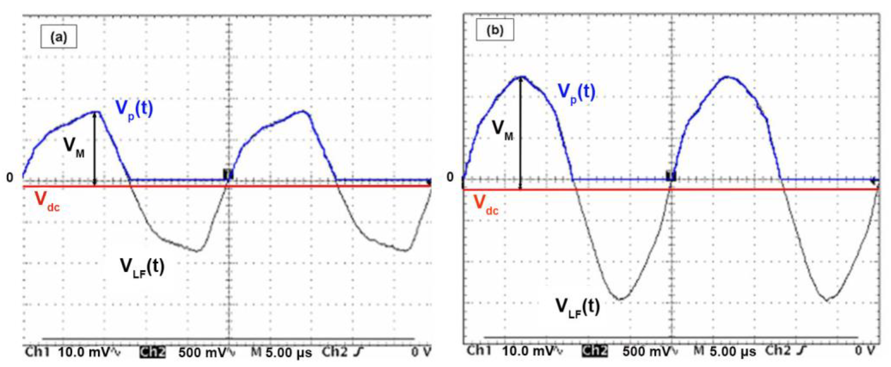
  • The plasma potential Vp: near a surface, the plasma interacts with it. Because of their mass, the speed of electrons is much greater than that of ions. Thus, at the initial instant, the flow of electrons on a wall is much greater than that of ions. The plasma then acquires a concentration of positive residual charges due to the excess of positive ions; this is the plasma potential, Vp. It is therefore positive with respect to the walls and is often used as a reference.
  • The floating potential Vf: it corresponds to the potential to which an isolated sample, immersed in a plasma, is fixed. It is due to the fact that this sample first charges negatively thanks to high mobility of electrons. The sample stabilizes at this potential Vf when the balance between electronic and ionic flux is achieved.
  • The self-bias voltage, Vdc, appears on the active electrode with the introduction of a blocking capacitor between the generator and the cathode. During the first positive half-period of a cycle, electrons are attracted to the cathode, causing negative charges to build up due to the existence of the blocking capacity. An identical phenomenon is obtained, but in the opposite direction for the ions during the next negative half-period. However, due to the difference in mobilities of ions and electrons, this variation in the potential of the electrode is greater during positive alternation. Thus, after a few periods, a balance will be reached between the electronic and ionic currents and the voltage at the level of the cathode stabilizes at the continuous value Vdc. The value of this voltage depends in particular on the area ratio between the grounded electrode (or the reactor) and the active electrode. It is given by Turban [35] as follows:
    V d c = [ 1 ( A a A c ) n ] × V ¯ p
    with, Aa: area of the anode; Ac: area of the cathode; V ¯ p : mean plasma potential; n: pressure-dependent factor. The influence of the ratio of the areas of the active electrode to that of the mass, on the shapes of the plasma potential V ¯ p , and of the excitation signal V(t) (Figure 1) for direct and capacitive coupling is discussed by [36].

2.3. Example of Deposition

Deposition was carried out in an industrial-size Low-Frequency PECVD reactor with a capacitively coupled electrode configuration. The lower electrode serving as substrate holder and having a diameter of 250 mm was powered via a 40-kHz LF transmitter. The samples were positioned directly on this substrate holder. A shower, with a diameter of 250 mm, ensured the gases inlet homogeneously into the chamber. The shower to substrate holder distance was kept constant at 200 mm. The pumping unit consisted of a primary pump and a roots and a turbomolecular pump. The based vacuum achieved was of the order of 2–4 × 10⁻⁶ mbar. The pressure was regulated using a rolling valve. The temperature of the substrates is floating and measured using a thermocouple. For the series of deposits carried out with higher substrate temperatures, an additional plate provided with heating resistors was added to the device.
The discharge power supply was an Advanced Energy PE2500 (Advanced energies, Metzingen, Germany), associated with an integrated tuning box.
A gas mixture of cyclohexane (C6H12) and hydrogen was used to synthesize the a-C:H based layers. The choice of the precursor is very important for this type of coating because it has a direct effect on the growth rate. Cyclohexane is advantageous over other precursors, as shown by J. Robertson [19], because it shows a good compromise between a low ionization potential (below 10 eV) and a relatively high deposition rate (2.5 μm/h) in their deposition conditions.
Electrical measurements of the plasma were performed using a Tektronix high-voltage probe (P6015A, Tektronicx, Les Ullis, France) directly connected to the polarized plate and connected to an oscilloscope. These measurements made it possible to see the electrical signal on the plate during the deposition process. Figure 1 shows two examples of signals obtained in the case of a cyclohexane/hydrogen gas mixture for two different plasma powers. These signals highlight the different electrical parameters defined in the previous paragraph, namely, the applied voltage VLF(t), its average value VM, the plasma voltage V ¯ p , and the self-bias voltage Vdc (Figure 1).
It thus appears that the geometric and electrical configurations of the reactor used in this study led to a relatively low self-bias voltage (even with a high power, as illustrated in Figure 1b), and always much lower at the average plasma potential. This result was also observed with other C6H12/H2 ratios and other working pressures.
In this study, the main parameter was, therefore, not this self-bias voltage since it is not directly representative of ionic energy here, unlike the case of an RF power supply in capacitive coupling. In the present case, the monitored parameter corresponded to the value of the voltage VM of the signal VLF(t), which represents the total bias voltage applied to the substrate holder. This voltage, in the present study, was defined by:
V ¯ p = ( V M + V d c ) 2   or   V M = 2 V ¯ p V d c
More precisely, the polarization voltage values given in this study was V M 2 (if we consider a perfect sinusoidal signal) because the value given by the power supply is a Root-Mean-Squared (RMS) value of the signal and not an average value.

3. Examples of DLC Based Films Obtained by LFPECVD

3.1. Characterization Methods

13C Nuclear Magnetic Resonance (NMR) spectra were recorded with a 4-mm Bruker CPMAS (Mannheim, Germany) probe head on a Bruker AVANCE 400 spectrometer operating at 100.62 MHz for 13C frequency. The experimental details are given in [33]. Raman spectra were recorded at room temperature with a Jobin-Yvon Dilor (HORIBA, Longjumeau, France) spectrophotometer. Two different wavelengths were used in this study: 514 nm and 633 nm. The power was kept below 2.5 mW to avoid "graphitization" phenomena. The silicon calibration was performed using the lines of silicon (521 cm−1) and mercury (1122 cm−1). The broadband spectra were performed in several spectral ranges, each range being performed in 2 × 120 s, i.e., 4 min per range. The peak characteristics were then obtained by fitting the spectra with Gaussian functions.
Residual stress was determined using a bending method. Curvature of stainless-steel foils was measured by optical profilometer (Altisurf 520, Altimet, Marin, France) and the stress level was deduced from the Stoney’s equation [37]. Hardness and Young’s modulus of coatings were evaluated by means of a Nano Hardness Tester (CSM Instruments, Anton Paar, Buchs, Switzerland) using a Berkovich diamond tip. Values were calculated using the Oliver and Pharr method [38]. A ball-on-disk tribometer (CSM Instruments) was used for friction coefficient measurements. Six-mm Al2O3 balls were used as the mating material and a 3 N load was applied to the system, corresponding to an initial Hertzian contact pressure of about 830 MPa. Sliding speed was kept at 0.2 m·s−1 for a fixed number of 50,000 cycles. All tests were performed in an ambient environment (20 °C and 40% RH).

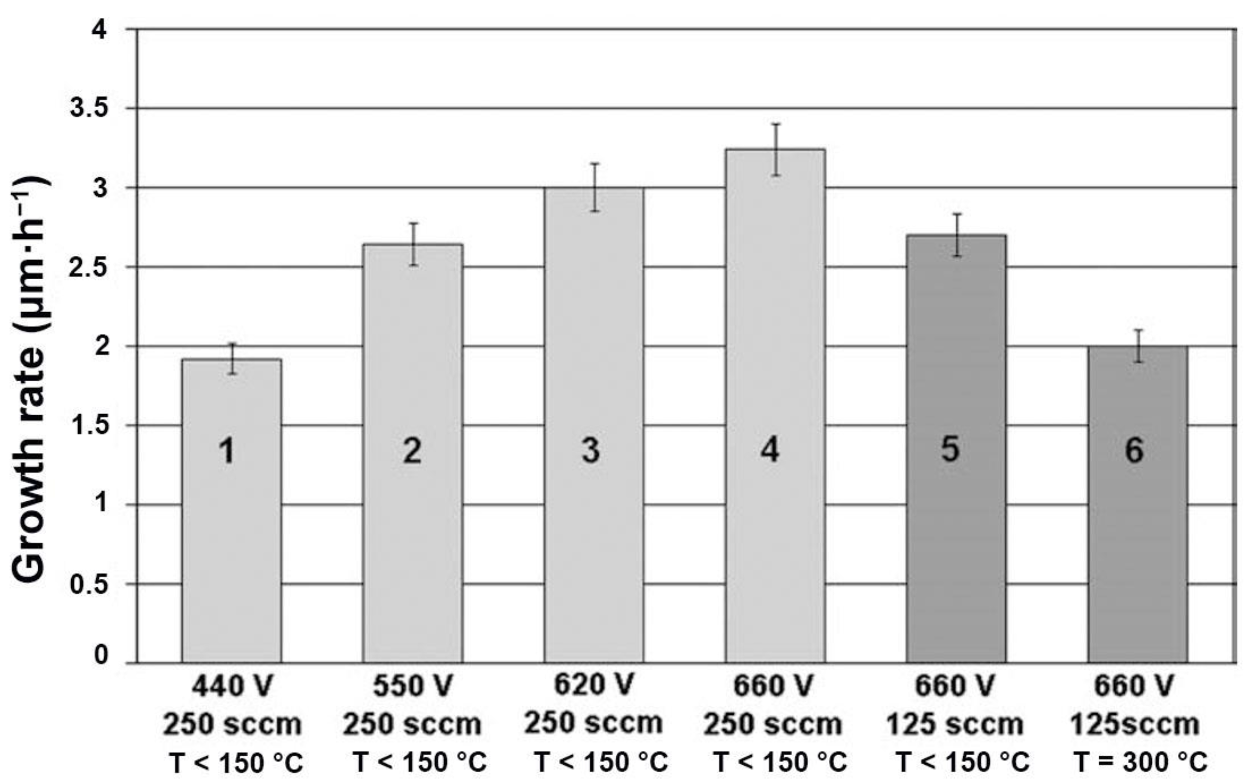
3.2. Deposition Rate

Deposition rate clearly decreases with the bias voltage, which can be explained by an improved precursor dissociation rate (samples 1 to 4, Table 1 and Figure 2) favored by higher plasma power. Moreover, it was shown that the deposition rate decreased slightly at 300 °C (sample 6, Table 1 and Figure 2) compared with that deposited below 150 °C. This can be due to an adsorption–desorption equilibrium, which is the rate limiting process in the investigated temperature range [39]. The deposited atoms and radicals would diffuse over the surface in a weakly bound, adsorbed layer before being incorporated into the film.

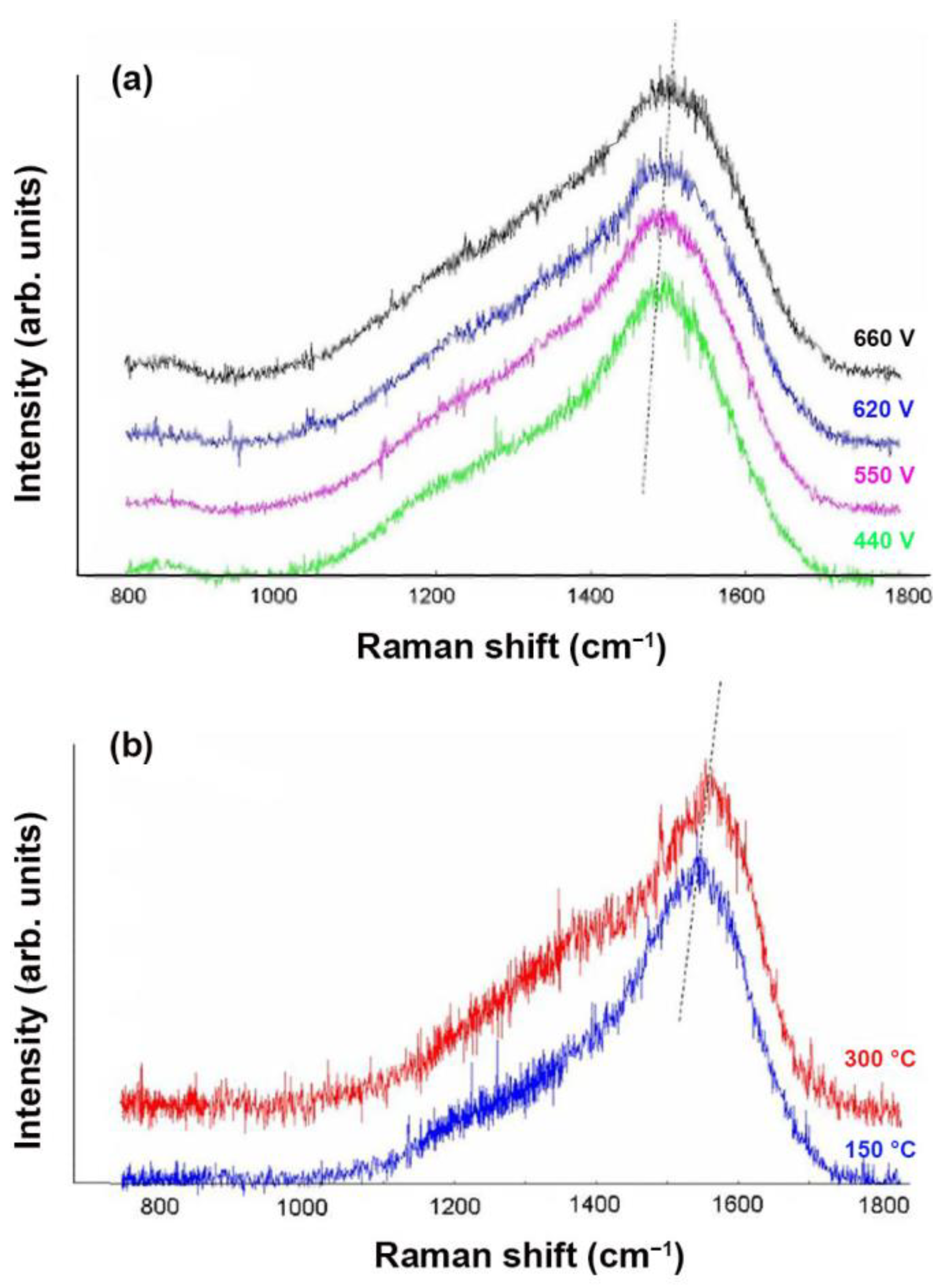
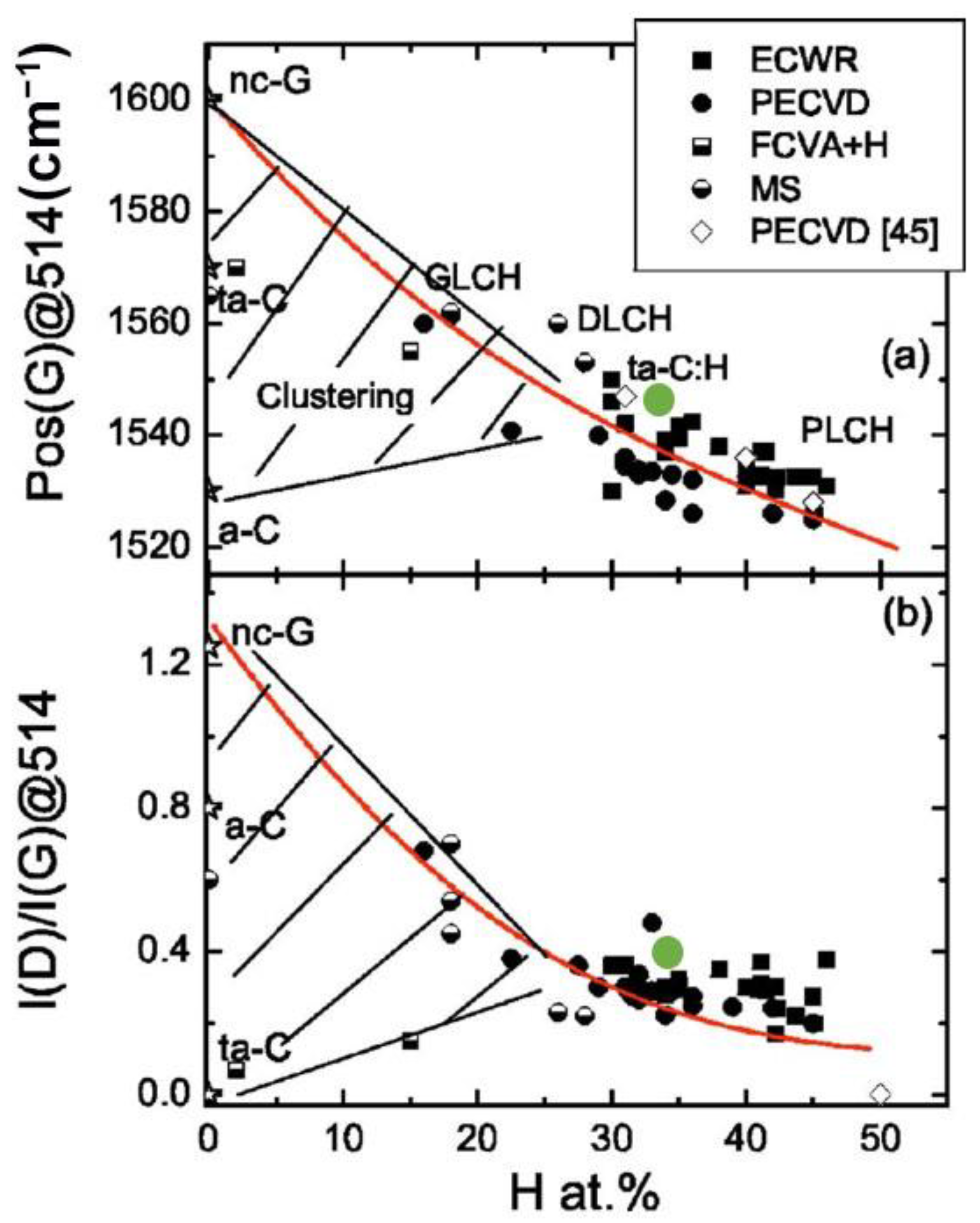
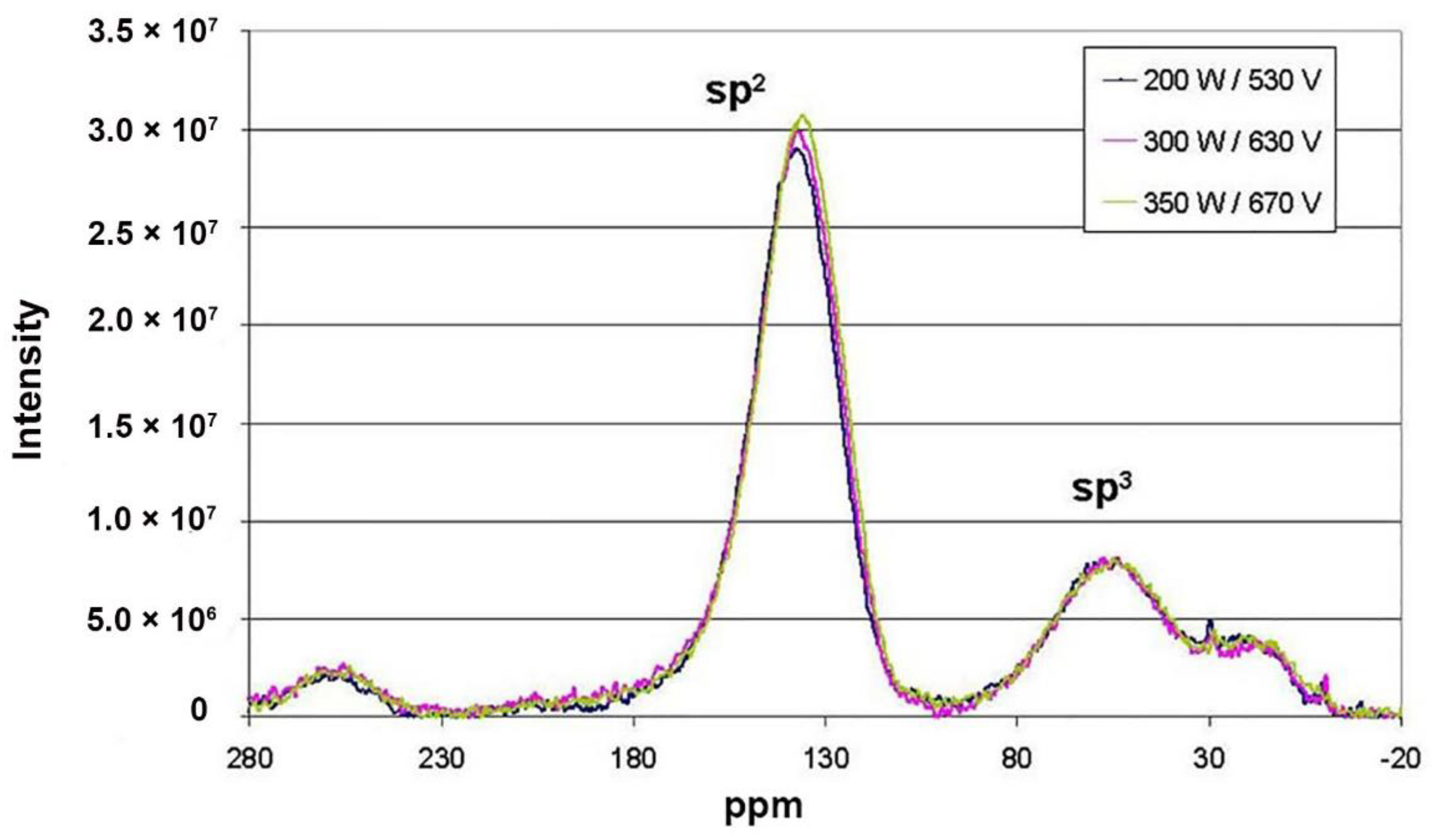
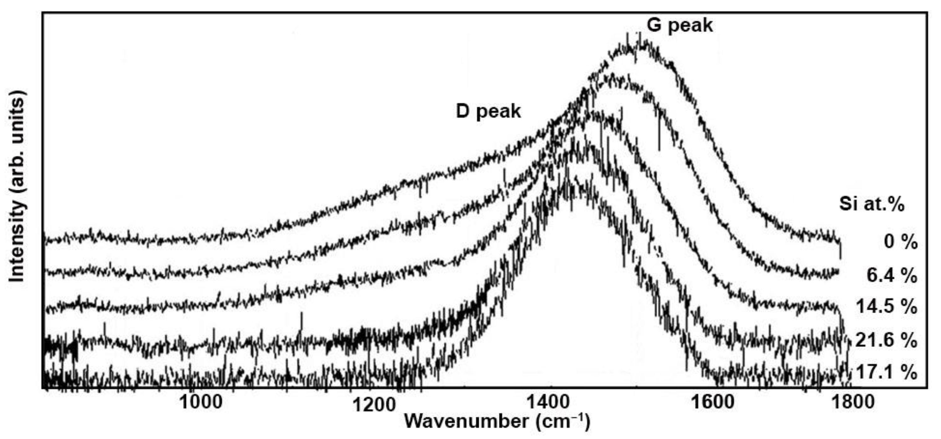
3.3. Structure of a-C:H Films

Various information can be obtained from Raman spectra. The two main parameters of interest are the position of the G band and the ID/IG ratio of two bands intensities.
It is well known that a displacement of the G band position towards the largest wave numbers is associated with an increase in the sp2 hybridization [40], while the increase in the ID/IG ratio is associated with an increase in the size of sp2-type aggregates in the carbon matrix [41]. Concerning the influence of the bias voltage, two exciting wavelengths (λ = 514 and λ = 633 nm) were tested while the influence of the substrate temperature was analyzed only with a single wavelength of 514 nm.
Figure 3 shows Raman spectra of the different characterized a-C:H films. The D band on each of these spectra confirmed the presence of sp2 carbon in aromatic form as well as a disordered character of the films, which is the case for an a-C:H coating [19].
The changes in the position of G band and ID/IG ratio, as a function of the deposition and analysis parameters, are reported in Table 2.
First, these values highlight the influence of the exciting wavelength on the spectra. It can be seen that even if the evolutions were similar, an increase in wavelength from 514 nm to 633 nm shifted the G band towards the lowest wavenumbers and increased the value of the ID/IG ratio. The shift in the position of peak G, called dispersion of peak G, actually reflects the degree of disorder in the material. The study of this dispersion over a wide range of wavelengths (from IR to UV) makes it possible to separate the materials into two classes depending on the nature of the sp2 bonds (aromatic chains or rings). The different positions of G peak obtained here for the wavelengths of 514 nm and 633 nm indicated that the film also contained aliphatic sp2 bonds [43]. Regarding the evolution of the spectra, whatever the wavelength used, the values indicated a displacement of the G band towards the highest wavenumbers when the bias voltage increased. The same phenomenon occurred when the substrate temperature increased from 150 °C to 300 °C.
Two hypotheses can explain this evolution.
The first comes from the model developed by Beeman [40] and corresponds to an increase of the sp2 hybridization. The second is based on the intrinsic stress evolution. Indeed, the modification of the stress level leads to an evolution of the inter-atomic strengths within the films and therefore an evolution of the atomic vibration frequencies, which are the origin of Raman peaks positions [44].
This hypothesis will be verified in the following paragraph by determining the internal stresses of the films and by estimating the Csp2/Csp3 ratios from the NMR analyses.
For ID/IG ratio, it can be observed that it remained quite constant when the bias voltage increased while a slight variation was observed when the substrate temperature changed. This variation may lead to an increase in the size of the sp2 carbon aggregates in the material.
These Raman analyses also allow the comparison of these films with other existing DLC coatings. Figure 4 shows the evolution of the position of G band and ID/IG ratio as a function of the percentage of hydrogen for different DLC coatings [45]. Green points correspond to the values obtained in this study; their positions appear clearly in the range of a-C:H cotings obtained by PECVD.

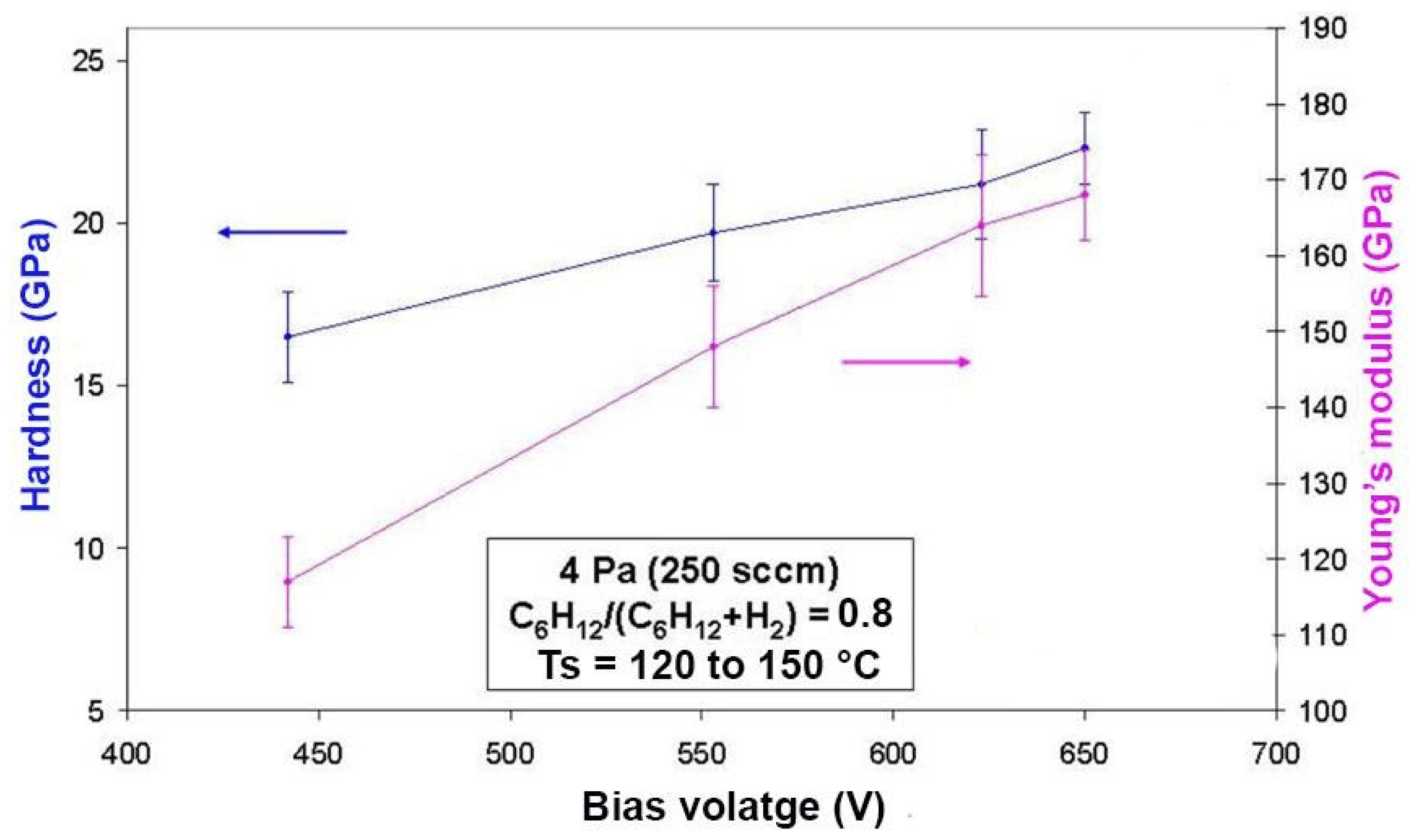
3.4. Mechanical Properties of a-C:H Films

Figure 5 shows the evolution of the residual stresses values as a function of the bias voltage (Figure 5a) and the substrate temperature (Figure 5b). All films had compressive stresses and the values were between −400 MPa and −2200 MPa depending on the deposition parameters. These results, which show an overall increase in residual stresses with bias voltage and with substrate temperature, allow us to confirm the second hypothesis mentioned previously about the evolution of Raman spectra. In other words, an increase of bias voltage or of substrate temperature causes a modification of the carbon network, more precisely a reorganization of the sp2 carbons in aromatic form. This could lead to G band displacement in Raman spectra (Table 2). The increase in C–C bonds thus is accompanied by an increase in the intrinsic stresses of the films. This phenomenon is particularly visible above 600 V, which is a threshold in these deposition conditions.
Nuclear Magnetic Resonance (NMR) appears to be the most reliable concerning the quantitative analysis of sp2/sp3 ratio of carbon hybridization states [19]. Figure 6 shows the NMR spectra (HPDEC: High Power Proton Decoupling) of 13C corresponding to three films deposited with different bias voltages (530 V, 630 V, and 670 V). These spectra are a combination of two main peaks located around 50 and 140 ppm and are associated respectively to sp3 and sp2-hybridized carbons. No significant change was observed, indicating that the proportions of Csp2 and Csp3 were similar for the three samples. This observation therefore allows us to validate the second hypothesis on G band displacement (Table 2), which would come from the variation of the internal stresses rather than from an increase of sp2 hybridization since this one was not observed in NMR. From NMR analyses, the sp2/sp3 atio is about three in these films, which seems quite consistent with that of the G band position observed on the corresponding Raman spectra.
Hardness and Young modulus increased with bias voltage (Figure 7) and substrate temperature (Table 3). Contrary to the results from other studies [46], no optimum of hardness and Young modulus was observed with plasma power. A complex precursor was used in the present case; during a-C:H growth, species as CmHn+ molecular ion hit the surface and broke up, sharing their kinetic energy between the individual carbon atoms. The key parameter, then, controlling the a-C:H film properties corresponds to the effective energy per C atom. The energy per C atom necessary to obtain an optimum on hardness and Young modulus values of a-C: H films will require an incident ion energy six times higher in case of cyclohexane compared with methane. This could explain the lack of optimum in this case [33]. In this investigation, plasma power and substrate temperature induce a structural and mechanical reinforcement of a-C:H films which is associated with a decrease in friction coefficient [33]. As far as the sp2/sp3 ratio remains constant (about 3), this reinforcement can probably be attributed to a carbon network rearrangement, which is associated with a shift of G band peak toward higher wavenumbers (Table 2).

3.5. Si Doped DLC

One of the different methods to reduce the stress of a-C:H films is based on the use of various film compositions, for instance, with silicon addition [33] by means of Low-Frequency enhanced chemical vapor deposition co-deposition. Recently, metal-containing hydrogenated diamond-like carbon coatings (Me-DLC) have attracted great interest since their initial appearance 3 decades ago [47,48,49]. The Me-C:H coating has high elasticity and a low friction coefficient, which can be beneficial for many engineering applications [50,51,52,53,54]. In addition, the hardness can be adapted to find a compromise between excellent behavior and low friction coefficient [27]. Many transition metals have been tested, for instance, Ti [55,56,57,58,59], Cr [60,61,62], W [63,64], Al [65,66,67], and Cu [68,69]. These metals are often introduced in DLC by coupling a magnetron sputtering discharge to the Low-Frequency enhanced chemical vapor deposition discharge [26].
TMS (tetramethylsilane, Si(CH3)4) can be added to the cyclohexane and hydrogen mixture as a second precursor for co-deposition of a-SiC:H (Si doped DLC) [33]. R is defined as TMS flow rate/(TMS + Cyclohexane) total flow rate. The deposition rate increased from 2.7 to 3.5 μm/h when R rose to 0.5 and stabilized when 0.5 < R < 1. This increase can be attributed to a lower ionization potential of TMS compared with other hydrocarbon precursors. The result is consistent with that of J.W. Yi et al. [70] and A. Bendavid et al. [71]. Table 4 gathers results on these a-SiC:H films: composition, hardness, Young modulus, and residual stress according to various R values.
Figure 8 shows Raman spectra in function of Si content in the films, which depend on TMS content in the gas mixture (R). When silicon is added in a-C:H films, there was a clear shift of G peak position toward lower wavenumbers and the D peak disappeared. These evolutions correspond to those already highlighted by Papakonstantinou et al. [72] for Si-doped DLC films obtained from TMS/C2H2 mixtures. G peak downshift can be attributed to Si–C bonds formation (3.10 eV) which has a lower energy than C–C bonds (3.70 eV). Moreover, compressive stress, which decreases with increasing Si content, can also explain this Raman result. The evolution of the D peak could be due to the opening of Csp2 rings when silicon is added in the structure.
Addition of Si is interesting because it promotes a significative reduction of the residual compressive stress of a-C:H films without degrading other properties (Table 4). A slight decrease of hardness and Young modulus occurred as Si content increased, essentially due to the change of bonds; for instance, Si–H and Si–C with lower energy than that of C–C. However, the friction coefficient decreased significantly when Si content increased. This result can be explained by SiO2 particles synthesis during the friction process. Anyway, friction coefficient of silicon-doped a-C:H films can be measured below 0.05 for R < 0.5 (Si content below 14.5 at.%).

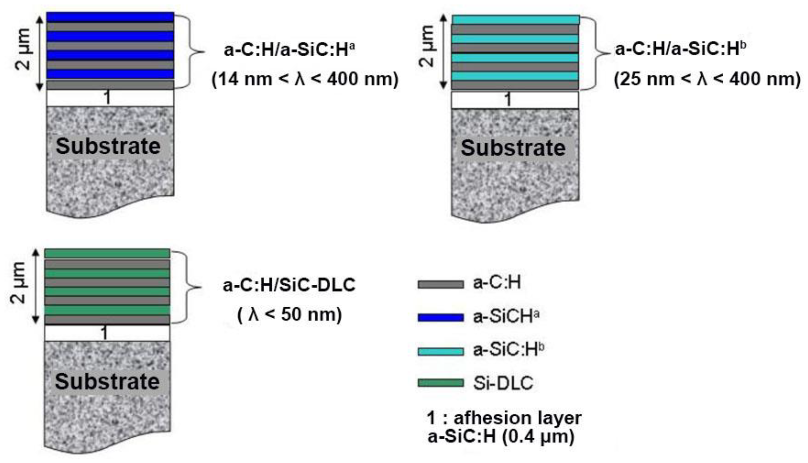
3.6. Multilayering Approach

The period (λ) of a multilayer system corresponds to the sum of the thicknesses of two consecutive layers forming the stack (one a-C:H layer and one a-SiC:H or Si-DLC layer). Different periods were studied here, but the total number of layers was always adjusted to maintain a final thickness of about 2 μm. The objective of this study was to highlight the influence of the nature and the thickness of the layers on the mechanical properties of the multilayer systems (residual stresses, hardness, and Young’s modulus, tribological properties). For that, four elementary layers (one a-C:H layer, two different a-SiC:H layers, and one Si-DLC layer) were selected.
Table 5 summarizes the main deposition parameters as well as the hardness, Young’s modulus, and residual stresses values of these four selected monolayers. The multilayer systems correspond to the association of a-C:H coating with one of the other three layers. These three configurations are interesting because they allow us to study different cases:
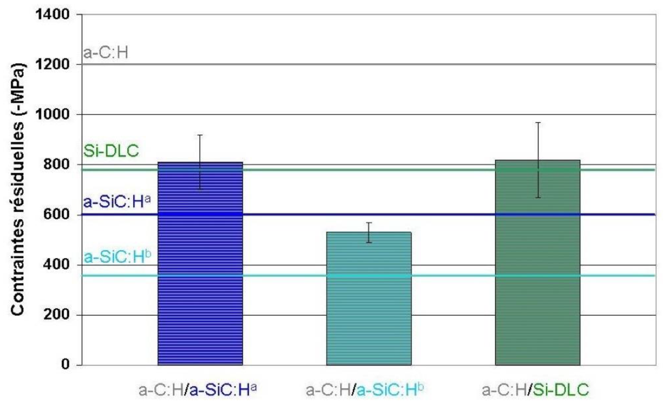
  • an a-C:H/a-SiC:Ha system for which the two elementary layers have similar hardness and Young’s modulus but different residual stress values,
  • an a-C:H/a-SiC:Hb system for which the two elementary layers have very different hardnesses, Young’s modulus and levels of residual stresses,
  • an a-C:H/Si-DLC system for which the configuration is identical to that of the first stack, namely hardness and Young’s modulus similar for the two layers but with lower residual stress values for the Si-DLC layer. The difference arises, in this case, from the tribological properties of the Si-DLC layer (with R = 0.2), which are clearly superior to those of the two a-SiC:H layers.
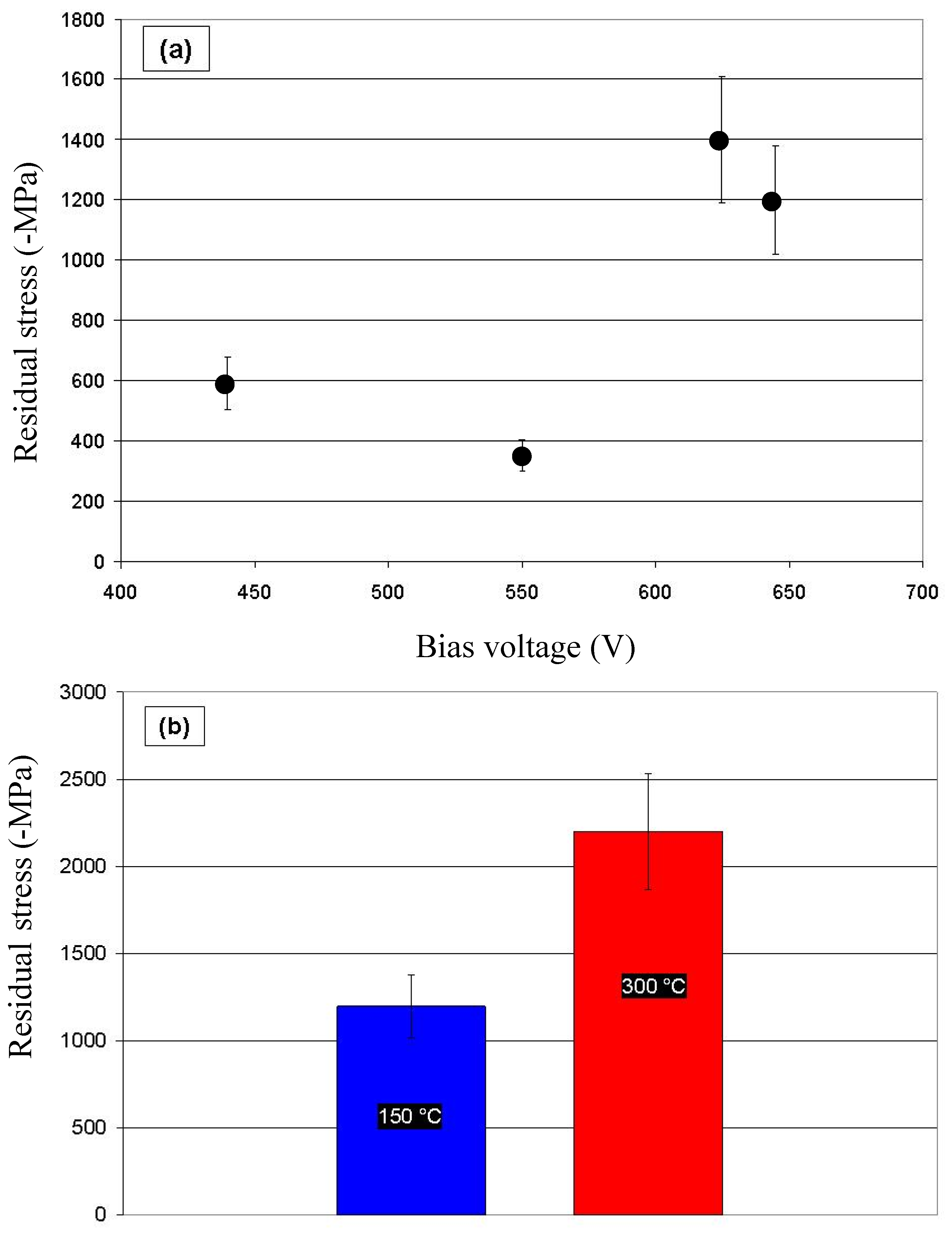
The tested periods were between 14 nm and 400 nm for a-C:H/a-SiC:Ha stacks, between 25 nm and 400 nm for a-C:H/a-SiC:Hb stacks, and only a only 50 nm was studied for a-C:H/Si-DLC stacking. In each case, the thickness of the multilayer was set at 2 μm, varying, then, the total number of layers between 286 for a period of 14 nm and 10 for a period of 400 nm. These systems are schematically shown in Figure 9.

3.6.1. Stress

Compressive residual stress was between −850 and −750 MPa for a-C:H/a-SiC:Ha films, whereas it was between −600 and −500 MPa for a-C:H/a-SiC:Hb coatings with different period thickness. For both a-C:H/a-SiC:Ha and a-C:H/a-SiC:Hb systems, whatever the thickness of the layers constituting the stacks, the values of the residual stresses of the multilayers ranged between those of two reference monolayers. It was the case for a period of 50 nm (Figure 10).
a-C:H/Si-DLC multilayer films were deposited with a period of 50 nm. Figure 10 shows their residual stress in comparison with those of a-C:H and Si-DLC monolayers (R = 0.2) as well as with the values obtained for previous multilayers a-C:H/a-SiC:Ha and a-C:H/a-SiC:Hb (with the same 50 nm). The results showed that this third system achieved, for a period of 50 nm, a level of residual stresses lower than the average of the stress values of the two monolayers.

3.6.2. Hardness and Young’s Modulus

The hardness and Young’s modulus of a-C:H/a-SiC:Ha and a-C:H/a-SiC:Hb multilayer systems (Table 6) were measured as a function of the stacking period. The total thickness of these monolayer and multilayer films remained unchanged, about 2 µm.
The results highlight two points:
  • Whatever the nature of stacking a-C:H/a-SiC:Ha or a-C:H/a-SiC:Hb, evolutions of hardness and Young’s modulus as a function of the period are not significant. In particular, no increase in hardness could be observed even for the smallest period of 14 nm thick;
  • For the two multilayer systems, hardness and Young’s modulus values were between those of the two monolayers constituting the stack and even appear very close to their average value. This appeared more clearly in the second case for which the properties of the two monolayers are very different. Each multilayer stack being composed of an identical proportion of a-C:H and a-SiC:H film, the obtained values therefore seem to respect the “law of mixtures”.
These mechanical behaviors, observed here for these stacks of amorphous layers, differ from those frequently encountered for crystalline multilayer systems. These systems are very often characterized by structural reinforcement for the thicknesses of weakest periods [73,74].
This result, however, does not agree with the work carried out by Logothedis et al. [75] on stacked layers of amorphous a-C carbon, one rich in Csp3 and the other rich in Csp2. Indeed, they observed, despite the amorphous nature of their layer, similar changes to those measured for crystalline systems, namely an increase in the hardness of the multilayer system when the thickness of the period changes from 45 nm to 14 nm. In the present case, this behavior could be explained by the fact that, unlike the case studied by Logothetidis et al., the structures of a-C:H and a-SiC:H layers are different and that the interactions, which can exist when two associated layers are of similar a-C nature, do not occur when the structures of the layers are different (Raman analyses).
Table 6 gathers the values of hardness and Young’s modulus obtained for a-C:H/Si-DLC stack using a period of 50 nm compared with those of other two multilayer systems (a-C:H/a-SiC:Ha and a-C:H/a-SiC:Hb). Values of four monolayers are also presented. The four-monolayer stack has a behavior similar to that of other two multilayer systems. In other words, it does not show any structural reinforcement, for the period of 50 nm, compared with two monolayers (a-C:H and Si-DLC). Due to the properties of these monolayers, its hardness and Young’s modulus are equivalent to those of a-C:H/a-SiC:Ha system.

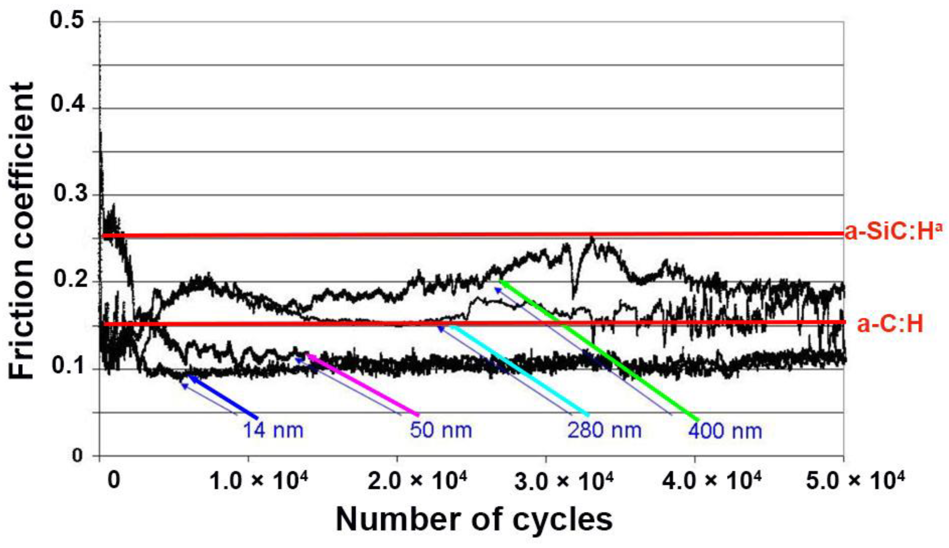
3.6.3. Friction Behavior-Influence of the Period in a-C:H/a-SiC:Ha Stack

In this section, only the tribological properties of a-C:H/a-SiC:Ha multilayer system, with the highest hardness and Young’s modulus values, were reported as a function of the stacking period.
Figure 11 shows evolution of the friction coefficients as a function of the number of cycles of four a-C:H/a-SiC:Ha stacks with periods of 14 nm, 50 nm, 280 nm, and 400 nm. The curves showed values between 0.09 and 0.25 for these four multilayer films. Under the same conditions, a-C:H single-layer coating has a friction coefficient of ~0.15 with strong instabilities while a-SiC:Ha coating has a coefficient friction of ~0.25 with a lower resistance to wear. Moreover, the stacks with the smallest periods (14 nm and 50 nm) exhibited lower and more stable friction coefficients than those with the largest periods (280 nm and 400 nm).
It is important to specify that the last layer of the stack was an a-SiC:Ha layer, which has, under these same test conditions, a higher friction coefficient and a greater wear rate than those of the a-C:H layer.
Thus, for the highest periods, the thicker a-SiC:Ha layers at the surface (140 nm for the 280 nm period and 200 nm for the 400 nm period) could explain the higher friction coefficients at the beginning of the test (Figure 11). The instabilities occuring then as a function of the number of cycles could come from the differences in behavior of the two layers of the stack.
For the first two stacks with periods of 14 nm and 50 nm, the smaller thicknesses of these a-SiC:Ha layers (respectively 7 nm and 25 nm) have less significant impact on the evolution of the friction coefficient. This latter also has lower values compared to those of a-C:H single-layer film as well as greater stability as a function of the number of cycles.

4. Conclusions

The low-frequency plasma-enhanced chemical vapor deposition in cyclohexane atmospheres is an easy-to-implement technology for carbon-based coatings deposition. LFPECVD (like RF PECVD), which has the capacity to be implemented in any scale, is widely used in industry.
This work aimed at gathering the main principles of LF discharges as well as giving examples of its versatility for depositing doped diamond-like carbon and multilayered coatings. In the case of a-C:H, increasing the bias voltage or the substrate temperature led to a reorganization of sp2 carbons in aromatic form, causing a shift of G band peak toward higher wavenumbers. This reorganization in aromatic form results of an increasing in C–C bonds, which is associated with a growth of the intrinsic stresses and a decrease of the friction coefficient of the films.
Si-doped DLC films were deposited by LFPECVD co-deposition from cyclohexane and tetramethylsilane mixtures. Increasing Si content, G peak position shifts toward lower wavenumbers, which is attributed to Si–C bonds, because of their lower energy compared with that of C–C bonds. The addition of silicon reduced the residual compressive stress of a-C:H films without significant change of the hardness and Young modulus, however the friction coefficient decreased significantly when Si content increased.
Regarding the multilayering approach, whatever the thickness of the layers forming the stacks, the values of their residual stresses were all between those of two reference monolayers. Hardness and Young’s modulus values were also between those of the two monolayers constituting the stack, and they even appear very close to their average value. The friction coefficient seems to depend essentially on the sliding property of the top layer.

Author Contributions

Conceptualization, F.S. (Frederic Schuster), F.S. (Frederic Sanchette) and A.B.; methodology, C.C. and C.D.; software, validation, F.S. (Frederic Sanchette) and A.B.; formal analysis, C.C. and C.D.; investigation, C.C.; resources, data curation, C.C., C.D. and F.S. (Frederic Sanchette); writing—original draft preparation, M.E.G., S.A. and F.S. (Frederic Sanchette); writing—review & editing, M.E.G.; visualization, M.E.G. and S.A.; supervision, F.S. (Frederic Sanchette); project administration, F.S. (Frederic Schuster), F.S. (Frederic Sanchette), and A.B.; funding acquisition, F.S. (Frederic Schuster). All authors have read and agreed to the published version of the manuscript.

Funding

This research received no external funding.

Institutional Review Board Statement

Data sharing is not applicable to this article.

Informed Consent Statement

Not applicable.

Data Availability Statement

Not applicable.

Conflicts of Interest

The authors declare no conflict of interest.

References

  1. Yee, M.J.; Mubarak, N.; Abdullah, E.; Khalid, M.; Walvekar, R.; Karri, R.R.; Nizamuddin, S.; Numan, A. Carbon nanomaterials źbased films for strain sensing application—A review. Nano-Struct. Nano-Objects 2019, 18, 100312. [Google Scholar] [CrossRef]
  2. Gopinath, K.P.; Vo, D.-V.N.; Prakash, D.G.; Joseph, A.A.; Viswanathan, S.; Arun, J. Environmental applications of carbon-based materials: A review. Environ. Chem. Lett. 2021, 19, 557–582. [Google Scholar] [CrossRef]
  3. Rathanasamy, R.; Sahoo, S.; Lee, J.H.; Das, A.K.; Somasundaram, M.; Palaniappan, S.K.; Sivaraj, S. Carbon-based Multi-layered Films for Electronic Application: A Review. J. Electron. Mater. 2021, 50, 1845–1892. [Google Scholar] [CrossRef]
  4. Sivakumar, E.; Senthilkumar, P.; Sreenivasan, M.; Krishna, R. Experimental investigation of H-DLC coated exhaust valve characteristics of a diesel engine. Mater. Today-Proc. 2020, 33, 675–681. [Google Scholar] [CrossRef]
  5. Ferhati, H.; Djeffal, F.; Boubiche, N.; le Normand, F. An efficient ITO-free transparent electrode based on diamond-like carbon with an engineered intermediate metallic thin-film. Sol. Energy 2020, 196, 327–335. [Google Scholar] [CrossRef]
  6. Rao, X.; Yang, J.; Chen, Z.; Yuan, Y.; Chen, Q.; Feng, X.; Qin, L.; Zhang, Y. Tuning C–C sp2/sp3 ratio of DLC films in FCVA system for biomedical application. Bioact. Mater. 2020, 5, 192–200. [Google Scholar] [CrossRef] [PubMed]
  7. Brown, S.; Lengaigne, J.; Sharifi, N.; Pugh, M.; Moreau, C.; Dolatabadi, A.; Martinu, L.; Klemberg-Sapieha, J.E. Durability of superhydrophobic duplex coating systems for aerospace applications. Surf. Coat. Technol. 2020, 401, 126249. [Google Scholar] [CrossRef]
  8. Schmellenmeier, H. Experimentelle Technik der Physik 1; Deutscher Verlag der Wissenschaften: Berlin, Germany, 1953; p. 49. [Google Scholar]
  9. Aisenberg, S.; Chabot, R. Ion-beam deposition of thin films of diamondlike carbon. J. Appl. Phys. 1971, 42, 2953–2958. [Google Scholar] [CrossRef]
  10. Holland, L.; Ojha, S. Deposition of hard and insulating carbonaceous films on an rf target in a butane plasma. Thin Solid Film. 1976, 38, L17–L19. [Google Scholar] [CrossRef]
  11. King, F. Datapoint thin film media. IEEE Trans. Magn. 1981, 17, 1376–1379. [Google Scholar] [CrossRef]
  12. Kano, M. DLC coating technology applied to sliding parts of automotive engine. New Diam. Front. Carbon Technol. 2006, 16, 201–210. [Google Scholar]
  13. Maurin-perrier, P.; Heau, C.; Riand, R.; Engelric, B. Nouvelles voies tribologiques pour l’industrie mécanique. Traitement Therm. 2005, 364, 41–44. [Google Scholar]
  14. Badiger, P.V.; Desai, V.; Ramesh, M. Performance of DLC coated tool during machining of MDN431 alloyed steel. Mater. Today-Proc. 2018, 5, 17360–17370. [Google Scholar] [CrossRef]
  15. Huang, L.; Yuan, J.; Li, C.; Hong, D. Microstructure, tribological and cutting performance of Ti-DLC/α-C: H multilayer film on cemented carbide. Surf. Coat. Technol. 2018, 353, 163–170. [Google Scholar] [CrossRef]
  16. Koszela, W.; Pawlus, P.; Reizer, R.; Liskiewicz, T. The combined effect of surface texturing and DLC coating on the functional properties of internal combustion engines. Tribol. Int. 2018, 127, 470–477. [Google Scholar] [CrossRef]
  17. Tinchev, S.; Nikolova, P.; Dyulgerska, J.; Danev, G.; Babeva, T. aC: H absorber layer for solar cells matched to solar spectrum. Ol. Energy Mater. Sol. Cells 2005, 86, 421–426. [Google Scholar] [CrossRef]
  18. Grill, A. Diamond-like carbon coatings as biocompatible materials—An overview. Diam. Relat. Mater. 2003, 12, 166–170. [Google Scholar] [CrossRef]
  19. Robertson, J. Diamond-like amorphous carbon. Mater. Sci. Eng. R Rep. 2002, 37, 129–281. [Google Scholar] [CrossRef] [Green Version]
  20. Guo, C.-Q.; Lin, S.-S.; Gao, D.; Shi, Q.; Wei, C.-B.; Dai, M.-J.; Su, Y.-F.; Xu, W.; Tang, P.; Li, H. Modulation of Si on microstructure and tribo-mechanical properties of hydrogen-free DLC films prepared by magnetron sputtering. Appl. Surf. Sci. 2020, 509, 145381. [Google Scholar] [CrossRef]
  21. Liu, J.; Li, L.; Wei, B.; Wen, F.; Cao, H.; Pei, Y.T. Effect of sputtering pressure on the surface topography, structure, wettability and tribological performance of DLC films coated on rubber by magnetron sputtering. Surf. Coat. Technol. 2019, 365, 33–40. [Google Scholar] [CrossRef]
  22. Ye, Y.; Wang, Y.; Ma, X.; Zhang, D.; Wang, L.; Li, X. Tribocorrosion behaviors of multilayer PVD DLC coated 304L stainless steel in seawater. Diam. Relat. Mater. 2017, 79, 70–78. [Google Scholar] [CrossRef]
  23. Santiago, J.; Fernández-Martínez, I.; Kozák, T.; Capek, J.A.; Wennberg, J.; Molina-Aldareguia, V.; Bellido-González, R.; González-Arrabal, M.; Monclús, M.A. The influence of positive pulses on HiPIMS deposition of hard DLC coatings. Surf. Coat. Technol. 2019, 358, 43–49. [Google Scholar] [CrossRef]
  24. Santiago, J.A.; Fernández-Martínez, I.; Sánchez-López, J.C.; Rojas, T.C.; Wennberg, A.; Bellido-González, V.; Molina-Aldareguia, J.M.; Monclús, M.A.; González-Arrabal, R. Tribomechanical properties of hard Cr-doped DLC coatings deposited by low-frequency HiPIMS. Surf. Coat. Technol. 2020, 382, 124899. [Google Scholar] [CrossRef]
  25. Wang, H.; Wang, L.; Wang, X. Structure characterization and antibacterial properties of Ag-DLC films fabricated by dual-targets HiPIMS. Surf. Coat. Technol. 2021, 410, 126967. [Google Scholar] [CrossRef]
  26. Bouabibsa, I.; Lamri, S.; Alhussein, A.; Minea, T.; Sanchette, F. Plasma investigations and deposition of Me-DLC (Me= Al, Ti or Nb) obtained by a magnetron sputtering-RFPECVD hybrid process. Surf. Coat. Technol. 2018, 354, 351–359. [Google Scholar] [CrossRef]
  27. Bouabibsa, I.; Lamri, S.; Sanchette, F. Structure, mechanical and tribological properties of Me-doped diamond-like carbon (DLC)(Me= Al, Ti, or Nb) hydrogenated amorphous carbon coatings. Coatings 2018, 8, 370. [Google Scholar] [CrossRef] [Green Version]
  28. Capote, G.; Mastrapa, G.; Trava-Airoldi, V. Influence of acetylene precursor diluted with argon on the microstructure and the mechanical and tribological properties of aC: H films deposited via the modified pulsed-DC PECVD method. Surf. Coat. Technol. 2015, 284, 145–152. [Google Scholar] [CrossRef]
  29. Capote, G.; Ramírez, M.; da Silva, P.; Lugo, D.; Trava-Airoldi, V. Improvement of the properties and the adherence of DLC coatings deposited using a modified pulsed-DC PECVD technique and an additional cathode. Surf. Coat. Technol. 2016, 308, 70–79. [Google Scholar] [CrossRef]
  30. Chang, S.-H.; Tang, T.-C.; Huang, K.-T.; Liu, C.-M. Investigation of the characteristics of DLC films on oxynitriding-treated ASP23 high speed steel by DC-pulsed PECVD process. Surf. Coat. Technol. 2015, 261, 331–336. [Google Scholar] [CrossRef]
  31. Chouquet, C.; Gavillet, J.; Ducros, C.; Sanchette, F. Effect of DLC surface texturing on friction and wear during lubricated sliding. Mater. Chem. Phys. 2010, 123, 367–371. [Google Scholar] [CrossRef]
  32. Chouquet, C.; Ducros, C.; Barrat, S.; Billard, A.; Sanchette, F. Mechanical properties of aC: H/Si-containing aC: H multilayered coatings grown by LF-PECVD. Surf. Coat. Technol. 2008, 203, 745–749. [Google Scholar] [CrossRef]
  33. Chouquet, C.; Gerbaud, G.; Bardet, M.; Barrat, S.; Billard, A.; Sanchette, F.; Ducros, C. Structural and mechanical properties of aC: H and Si doped aC: H thin films grown by LF-PECVD. Surf. Coat. Technol. 2010, 204, 1339–1346. [Google Scholar] [CrossRef]
  34. Lugo, D.; Silva, P.; Ramirez, M.; Pillaca, E.; Rodrigues, C.; Fukumasu, N.; Corat, E.; Tabacniks, M.; Trava-Airoldi, V. Characterization and tribologic study in high vacuum of hydrogenated DLC films deposited using pulsed DC PECVD system for space applications. Surf. Coat. Technol. 2017, 332, 135–141. [Google Scholar] [CrossRef]
  35. Turban, G. Les décharges luminescentes du type diode excites en radiofréquence. Modèles élémentaires et énergie d’impact des ions positifs, Interactions plasmas froids matériaux, Studies day Oléron 87. Unpublished work.
  36. Köhler, K.; Horne, D.; Coburn, J. Frequency dependence of ion bombardment of grounded surfaces in rf argon glow discharges in a planar system. J. Appl. Phys. 1985, 58, 3350–3355. [Google Scholar] [CrossRef]
  37. Stoney, G.G. The tension of metallic films deposited by electrolysis. Proc. R. Soc. Lond. A 1909, 82, 172–175. [Google Scholar]
  38. Oliver, W.C.; Pharr, G.M. An improved technique for determining hardness and elastic modulus using load and displacement sensing indentation experiments. Mater. Res. 1992, 7, 1564–1583. [Google Scholar] [CrossRef]
  39. Kersten, H.; Kroesen, G. On the temperature dependence of the deposition rate of amorphous, hydrogenated carbon films. J. Vac. Sci. Technol. A Vac. Surf. Film. 1990, 8, 38–42. [Google Scholar] [CrossRef] [Green Version]
  40. Beeman, D.; Silverman, J.; Lynds, R.; Anderson, M.J.P.R.B. Modeling studies of amorphous carbon. J. Phys. Rev. B 1984, 30, 870. [Google Scholar] [CrossRef]
  41. Ferrari, A.C.; Robertson, J. Interpretation of Raman spectra of disordered and amorphous carbon. J. Phys. Rev. B 2000, 61, 14095. [Google Scholar] [CrossRef] [Green Version]
  42. Sanchette, F.; El Garah, M.; Achache, S.; Schuster, F.; Chouquet, C.; Ducros, C.; Billard, A. University of Technology of Troyes, Troyes, France. Unpuplished work. 2021. [Google Scholar]
  43. Ferrari, A.C. Non-destructive characterisation of carbon films. In Tribology of Diamond-Like Carbon Films; Donnet, C., Erdemir, A., Eds.; Springer: Boston, MA, USA, 2008; pp. 25–82. [Google Scholar]
  44. Lejeune, M.; Benlahsen, M.; Bouzerar, R. Stress and structural relaxation in amorphous hydrogenated carbon films. Appl. Phys. Let. 2004, 84, 344–346. [Google Scholar] [CrossRef]
  45. Casiraghi, C.; Ferrari, A.; Robertson, J. Raman spectroscopy of hydrogenated amorphous carbons. J. Phys. Rev. B 2005, 72, 085401. [Google Scholar] [CrossRef] [Green Version]
  46. Tomasella, E.; Thomas, L.; Meunier, C.; Nadal, M.; Mikhailov, S. Coupled effects of bombarding ions energy on the microstructure and stress level of RFPECVD aC: H films: Correlation with Raman spectroscopy. Surf. Coat. Technol. 2003, 174, 360–364. [Google Scholar] [CrossRef]
  47. Butt, M.; Khaleeq-ur-Rahman, M.; Ali, D.; Akmal, A.; Naseem, S. Deposition and characterization of multilayer DLC: Mo thin films grown on silicon substrate by off-axis pulsed laser deposition technique. Appl. Surf. Sci. 2015, 331, 407–414. [Google Scholar] [CrossRef]
  48. Cooper, C.V.; Wang, R.; Yoon, H.K.; Taher, M.A. The microstructure and wear behavior of Cr-and W-DLC coatings sputter-deposited onto AISI 52100 substrates as elucidated using focused-ion-beam SEM. MRS Online Proc. Libr. 2021, 697, 36. [Google Scholar] [CrossRef]
  49. Mutafov, P.; Lanigan, J.; Neville, A.; Cavaleiro, A.; Polcar, T. DLC-W coatings tested in combustion engine—Frictional and wear analysis. Surf. Coat. Technol. 2014, 260, 284–289. [Google Scholar] [CrossRef]
  50. Dimigen, H.; Hübsch, H.; Memming, R. Tribological and electrical properties of metal-containing hydrogenated carbon films. Appl. Phys. Let. 1987, 50, 1056–1058. [Google Scholar] [CrossRef]
  51. Donnet, C. Recent progress on the tribology of doped diamond-like and carbon alloy coatings: A review. Surf. Coat. Technol. 1998, 100, 180–186. [Google Scholar] [CrossRef]
  52. Lee, K.-R.; Eun, K.Y.; Kim, K.-M.; Choi, K.-C. Application of diamond-like carbon films for anti-abrasion and low friction properties of VCR head drums. Surf. Coat. Technol. 1995, 76, 786–790. [Google Scholar] [CrossRef]
  53. Roth, D.; Rau, B.; Roth, S.; Mai, J.; Dittrich, K.-H. Large area and three-dimensional deposition of diamond-like carbon films for industrial applications. Surf. Coat. Technol. 1995, 74, 637–641. [Google Scholar] [CrossRef]
  54. Voevodin, A.; Prasad, S.; Zabinski, J. Nanocrystalline carbide/amorphous carbon composites. J. Appl. Phys. 1997, 82, 855–858. [Google Scholar] [CrossRef]
  55. Cui, J.; Qiang, L.; Zhang, B.; Ling, X.; Yang, T.; Zhang, J. Mechanical and tribological properties of Ti-DLC films with different Ti content by magnetron sputtering technique. Appl. Surf. Sci. 2012, 258, 5025–5030. [Google Scholar] [CrossRef]
  56. Jo, Y.J.; Zhang, T.F.; Son, M.J.; Kim, K.H. Synthesis and electrochemical properties of Ti-doped DLC films by a hybrid PVD/PECVD process. Appl. Surf. Sci. 2018, 433, 1184–1191. [Google Scholar] [CrossRef]
  57. Ma, G.; Gong, S.; Lin, G.; Zhang, L.; Sun, G. A study of structure and properties of Ti-doped DLC film by reactive magnetron sputtering with ion implantation. Appl. Surf. Sci. 2012, 258, 3045–3050. [Google Scholar] [CrossRef]
  58. Qiang, L.; Gao, K.; Zhang, L.; Wang, J.; Zhang, B.; Zhang, J. Further improving the mechanical and tribological properties of low content Ti-doped DLC film by W incorporating. Appl. Surf. Sci. 2015, 353, 522–529. [Google Scholar] [CrossRef]
  59. Yang, W.J.; Sekino, T.; Shim, K.B.; Niihara, K.; Auh, K.H. Deposition and microstructure of Ti-containing diamond-like carbon nanocomposite films. Thin Solid Films. 2005, 473, 252–258. [Google Scholar] [CrossRef]
  60. Amanov, A.; Watabe, T.; Tsuboi, R.; Sasaki, S. Fretting wear and fracture behaviors of Cr-doped and non-doped DLC films deposited on Ti–6al–4V alloy by unbalanced magnetron sputtering. Tribol. Int. 2013, 62, 49–57. [Google Scholar] [CrossRef]
  61. Dai, W.; Ke, P.; Wang, A. Microstructure and property evolution of Cr-DLC films with different Cr content deposited by a hybrid beam technique. Vacuum 2011, 85, 792–797. [Google Scholar] [CrossRef]
  62. Dai, W.; Zheng, H.; Wu, G.; Wang, A. Effect of bias voltage on growth property of Cr-DLC film prepared by linear ion beam deposition technique. CVacuum 2010, 85, 231–235. [Google Scholar] [CrossRef]
  63. Baba, K.; Hatada, R.; Tanaka, Y. Preparation and properties of W-containing diamond-like carbon films by magnetron plasma source ion implantation. Surf. Coat. Technol. 2007, 201, 8362–8365. [Google Scholar] [CrossRef]
  64. Mercer, C.; Evans, A.; Yao, N.; Allameh, S.; Cooper, C. Material removal on lubricated steel gears with W-DLC-coated surfaces. Surf. Coat. Technol. 2003, 173, 122–129. [Google Scholar] [CrossRef]
  65. Dai, W.; Ke, P.; Wang, A. Influence of bias voltage on microstructure and properties of Al-containing diamond-like carbon films deposited by a hybrid ion beam system. Surf. Coat. Technol. 2013, 229, 217–221. [Google Scholar] [CrossRef]
  66. Dai, W.; Wang, A. Deposition and properties of Al-containing diamond-like carbon films by a hybrid ion beam sources. J. Alloys Compd. 2011, 509, 4626–4631. [Google Scholar] [CrossRef]
  67. Zhou, S.; Wang, L.; Xue, Q. The structure and tribological properties of aluminum/carbon nanocomposite thin films synthesized by reactive magnetron sputtering. Surf. Interface Anal. 2011, 43, 1057–1063. [Google Scholar] [CrossRef]
  68. Dai, W.; Wang, A.; Wang, Q. Microstructure and mechanical property of diamond-like carbon films with ductile copper incorporation. Surf. Coat. Technol. 2015, 272, 33–38. [Google Scholar] [CrossRef]
  69. Meškinis, Š.; Gudaitis, R.; Vasiliauskas, A.; Čiegis, A.; Šlapikas, K.; Tamulevičius, T.; Andrulevičius, M.; Tamulevičius, S. Piezoresistive properties of diamond like carbon films containing copper. Diam. Relat. Mater. 2015, 60, 20–25. [Google Scholar] [CrossRef]
  70. Yi, J.W.; Lee, Y.H.; Farouk, B. Effects of gas composition and rf power on properties of aC: H/SiC: H composite films grown by plasma-enhanced chemical vapor deposition. Thin Solid Film. 1998, 326, 154–159. [Google Scholar] [CrossRef]
  71. Bendavid, A.; Martin, P.; Comte, C.; Preston, E.; Haq, A.; Ismail, F.M.; Singh, R. The mechanical and biocompatibility properties of DLC-Si films prepared by pulsed DC plasma activated chemical vapor deposition. Diam. Relat. Mater. 2007, 16, 1616–1622. [Google Scholar] [CrossRef]
  72. Papakonstantinou, P.; Zhao, J.; Lemoine, P.; McAdams, E.; McLaughlin, J. The effects of Si incorporation on the electrochemical and nanomechanical properties of DLC thin films. Diam. Relat. Mater. 2002, 11, 1074–1080. [Google Scholar] [CrossRef]
  73. Ducros, C.; Sanchette, F. Multilayered and nanolayered hard nitride thin films deposited by cathodic arc evaporation. Part 2: Mechanical properties and cutting performances. Surf. Coat. Technol. 2006, 201, 1045–1052. [Google Scholar] [CrossRef]
  74. Martínez, E.; Romero, J.; Lousa, A.; Esteve, J. Mechanical strengthening in nanometric CrN/Cr multilayers measured by nanoindentation. J. Phys. D Appl. Phys. 2002, 35, 1880. [Google Scholar] [CrossRef]
  75. Logothetidis, S.; Kassavetis, S.; Charitidis, C.; Panayiotatos, Y.; Laskarakis, A. Nanoindentation studies of multilayer amorphous carbon films. Carbon 2004, 42, 1133–1136. [Google Scholar] [CrossRef]
Figure 1. Electrical signals recorded on the oscilloscope for a cyclohexane/hydrogen gas mixture (C6H12/H2 = 4) at 4 Pa for powers of 100 W (a) and 400 W (b).
Coatings 11 01225 g001
Figure 2. a-C:H Depositions Rates. Reproduced and modified from [33] with permission; Copyright 2010 Elsevier.
Coatings 11 01225 g002
Figure 3. RAMAN spectra of a-C:H films deposited at a pressure of 4 Pa, a C6H12/(C6H12 + H2) ratio of 0.8, then (a) different bias voltages (440 V, 550 V, and 620 V and 660 V) and a substrate temperature <150 °C (λ = 633 nm) and (b) substrate temperatures of 150 °C and 300 °C and a bias voltage of 660 V (λ = 514 nm).
Coatings 11 01225 g003
Figure 4. Evolution of G band position (a) and of ID/IG (b) ratio as a function of hydrogen content in the layers. Green dots correspond to the values obtained in this study for a deposit carried out at 620 V, 150 °C, at a pressure of 4 Pa (250 sccm) and a C6H12/(C6H12 + H2) ratio of 0.8. Reproduced and modified from [45] with permission; Copyright 2005 American Physical Society. Shortcuts are: ECWR for electron cyclotron wave resonance; PECVD for plasma enhanced chemical vapor deposition; FCVA+H for depositing ta-C by filtered cathodic vacuum arc; MS for magnetron sputtering; GLCH for graphite-like a-C:H; DLCH for diamond-like a-C:H; PLCH for polymer-like a-C:H.
Coatings 11 01225 g004
Figure 5. Evolution of the residual stresses as a function of: (a) the bias voltage (deposition temperature ≤ 150 °C) and (b) the temperature of the substrate (polarization voltage 660 V) for deposits made with a pressure of 4 Pa and a C6H12/(C6H12 + H2) ratio of 0.8.
Coatings 11 01225 g005
Figure 6. 13C direct excitation high-resolution solid-state NMR spectrum of a-C:H films elaborated at 550 V (sample 2), 620 V (sample 3), and 660 V (sample 4).
Coatings 11 01225 g006
Figure 7. Evolution of hardness and Young’s modulus as a function of bias voltage [42].
Coatings 11 01225 g007
Figure 8. Raman spectra of Si-doped a-SiC:H films as a function of Si content.
Coatings 11 01225 g008
Figure 9. Scheme of different a-C:H/a-SiC:Ha, a-C:H/a-SiC:Hb, and a-C:H/Si-DLC multilayer systems. The multilayer thickness is 2 μm.
Coatings 11 01225 g009
Figure 10. Residual stress of the three multilayer films with a period of 50 nm. The horizontal lines indicate the values of the residual stress of the monolayers.
Coatings 11 01225 g010
Figure 11. Evolution of the friction coefficients as a function of the number of cycles for four a-C:H/a-SiC:Ha films with periods of 14 nm, 50 nm, 280 nm, and 400 nm. Red lines give the friction coefficient level of a-C:H (0.15) and a-SiC:Ha (0.25) monolayers.
Coatings 11 01225 g011
Table 1. Deposition conditions of samples of a-C:H related to Figure 2; the film’s thickness is 2 μm for a deposition duration between 60–100 min. Reproduced and modified from [33] with permission; Copyright 2010 Elsevier.
SampleRamanERDA
λ = 514 nmλ = 633 nmTotal H Content (±2 at.%)
G Position (cm−1)ID/IGG Position (cm−1)ID/IG
115420.4115070.6033
215430.3615110.62-
315640.4215190.64-
4--15210.7033
515470.44--25
615670.73--26
Table 2. Values of the G band positions and on the ID/IG ratio for different films [42].
Deposition ConditionsRaman Parameters
Total Flow Rate (sccm)Bias Voltage (V)Ts (°C)λ = 514 nmλ = 633 nm
G Band Position (cm−1)ID/IGG Band Position (cm−1)ID/IG
25044012015420.4115070.6
25055013015430.3615110.62
25062014015460.4215190.64
250660150--15210.7
12566015015470.44--
12566030015670.73--
Table 3. Hardness and Young’s modulus values of two a-C:H films deposited at two substrate temperatures (150 °C and 300 °C) [42].
Pressure (Pa)Total Flow Rate (sccm)C6H12/(C6H12+H2)Bias Voltage (V)Ts (°C)Hardness (GPa)Young Modulus (GPa)
41250.866015021 ± 2160 ± 9
30026 ± 2190 ± 10
Table 4. Composition, hardness, Young modulus, and stress of Si-DLC films deposited at different R values.
RComposition (at.%)Residual Stress (-MPa)Hardness (GPa)Young’s Modulus (GPa)
CONSi
089.39.80.901200 ± 15021.5 ± 2160 ± 8
0.281.611.50.66.4780 ± 7019.5 ± 2142 ± 9
0.573.111.80.614.5450 ± 9017.5 ± 1.5141 ± 9
0.865.012.80.621.6350 ± 5018.5 ± 2143 ± 11
168.614.10.217.1400 ± 4018.5 ± 1144 ± 6
Table 5. Deposition parameters and mechanical properties of the four elementary layers selected for the study of multilayer films.
a-C:Ha-SiC:Haa-SiC:HbSi-DLC
Gas mixture (% of Each Gas)C6H12 (80)
H2 (20)
TMS (50)
Ar (50)
TMS (100)TMS (20)
C6H12 (70)
H2 (10)
Bias voltage (V)660660400660
Hardness (GPa)21 ± 220 ± 1.57 ± 120 ± 2
Young’s modulus (GPa)160 ± 9165 ± 853 ± 4142 ± 9
Residual stress (MPa)−1200−600−360−780
Table 6. Hardness and Young’s modulus values of three multilayer stacks with a period of 50 nm as well as the values corresponding to the monolayer films.
Monolayer Films (2 µm)Multilayer Films (2 µm)
Period 50 nm
a-C:Ha-SiC:Haa-SiC:HbSi-DLC
(R = 0.2)
a-C:H/
a-SiC:Ha
a-C:H/
a-SiC:Hb
a-C:H/
Si-DLC
Hardness (GPa)21 ± 220 ± 1.57 ± 120 ± 220 ± 215 ± 121 ± 2
Young’s modulus (GPa)160 ± 9165 ± 853 ± 4142 ± 9158 ± 8116 ± 5150 ± 8
Publisher’s Note: MDPI stays neutral with regard to jurisdictional claims in published maps and institutional affiliations.

