Determining Interface Fracture Toughness in Multi Layered Environmental Barrier Coatings with Laser Textured Silicon Bond Coat


Abstract
1. Introduction
2. Materials and Methods
2.1. Materials
2.2. Characterization
3. Results and Discussion
4. Conclusions
Author Contributions
Funding
Data Availability Statement
Acknowledgments
Conflicts of Interest
References
- Padture, N.P. Advanced structural ceramics in aerospace propulsion. Nat. Mater. 2016, 15, 804–809. [Google Scholar] [CrossRef] [PubMed]
- Miller, R.A. Thermal barrier coatings for aircraft engines: History and directions. JTST 1997, 6, 35–42. [Google Scholar] [CrossRef]
- Bansal, N.P.; Lamon, J. Ceramic Matrix Composites. Materials, Modeling and Technology; Wiley: Hoboken, NJ, USA, 2015; ISBN 978-1-118-23116-6. [Google Scholar]
- Koff, B. Spanning the globe with jet propulsion. In Proceedings of the 21st Annual Meeting and Exhibit, Arlington, VA, USA, 30 April−2 May 1991. [Google Scholar]
- Belmonte, M. Advanced ceramic materials for high temperature applications. Adv. Eng. Mater. 2006, 8, 693–703. [Google Scholar] [CrossRef]
- Jiang, D.; Zhang, L. High temperature ceramic matrix composites 8. In Proceedings of the A collection of papers presented at the HTCMC-8 Conference, Xi’an, China, 22–26 September 2013. [Google Scholar]
- Perepezko, J.H. Materials science. The hotter the engine, the better. Science 2009, 326, 1068–1069. [Google Scholar] [CrossRef] [PubMed]
- Eaton, H.E.; Linsey, G.D. Accelerated oxidation of SiC CMC’s by water vapor and protection via environmental barrier coating approach. J. Eur. Ceram. Soc. 2002, 22, 2741–2747. [Google Scholar] [CrossRef]
- Lee, K.N. Environmental barrier coatings for SiC f/SiC. In Ceramic Matrix Composites: Materials, Modeling and Technology; Bansal, N.P., Lamon, J., Eds.; Wiley: Hoboken, NJ, USA, 2015; pp. 430–451. ISBN 9781118832998. [Google Scholar]
- Yang, X.; Zhao-hui, C.; Feng, C. High-temperature protective coatings for C/SiC composites. J. Asian Ceram. Soc. 2014, 2, 305–309. [Google Scholar] [CrossRef]
- Xu, Y.; Hu, X.; Xu, F.; Li, K. Rare earth silicate environmental barrier coatings: Present status and prospective. Ceram. Int. 2017, 43, 5847–5855. [Google Scholar] [CrossRef]
- Lee, K.N.; Eldridge, J.I.; Robinson, R.C. Residual stresses and their effects on the durability of environmental barrier coatings for SiC ceramics. J. Am. Ceram. Soc. 2005, 88, 3483–3488. [Google Scholar] [CrossRef]
- Mauer, G.; Jarligo, M.O.; Mack, D.E.; Vaßen, R. Plasma-sprayed thermal barrier coatings: New materials, processing issues, and solutions. JTST 2013, 22, 646–658. [Google Scholar] [CrossRef]
- Wolf, M.; Mack, D.E.; Guillon, O.; Vaßen, R. Resistance of pure and mixed rare earth silicates against calcium–magnesium–aluminosilicate (CMAS): A comparative study. J. Am. Ceram. Soc. 2020, 281, 472. [Google Scholar] [CrossRef]
- Vaßen, R.; Jarligo, M.O.; Steinke, T.; Mack, D.E.; Stöver, D. Overview on advanced thermal barrier coatings. Surf. Coat. Technol. 2010, 205, 938–942. [Google Scholar] [CrossRef]
- Bakan, E.; Marcano, D.; Zhou, D.; Sohn, Y.J.; Mauer, G.; Vaßen, R. Yb2Si2O7 Environmental barrier coatings deposited by various thermal spray techniques: A preliminary comparative study. JTST 2017, 26, 1011–1024. [Google Scholar] [CrossRef]
- Kromer, R.; Costil, S.; Verdy, C.; Gojon, S.; Liao, H. Laser surface texturing to enhance adhesion bond strength of spray coatings—Cold spraying, wire-arc spraying, and atmospheric plasma spraying. Surf. Coat. Technol. 2018, 352, 642–653. [Google Scholar] [CrossRef]
- Courapied, D.; Kromer, R.; Berthe, L.; Peyre, P.; Costil, S.; Cormier, J.; Boustie, M.; Milhet, X. Laser adhesion test for thermal sprayed coatings on textured surface by laser. J. Laser Appl. 2016, 28, 22509. [Google Scholar] [CrossRef]
- Foldyna, J.; Sitek, L.; Ščučka, J.; Martinec, P.; Valíček, J.; Páleníková, K. Effects of pulsating water jet impact on aluminium surface. J. Mater. Process. Technol. 2009, 209, 6174–6180. [Google Scholar] [CrossRef]
- Meijer, J.; Du, K.; Gillner, A.; Hoffmann, D.; Kovalenko, V.S.; Masuzawa, T.; Ostendorf, A.; Poprawe, R.; Schulz, W. Laser machining by short and ultrashort pulses, state of the art and new opportunities in the age of the photons. Cirp Ann. 2002, 51, 531–550. [Google Scholar] [CrossRef]
- Garcia-Alonso, D.; Serres, N.; Demian, C.; Costil, S.; Langlade, C.; Coddet, C. Pre-/during-/post-laser processes to enhance the adhesion and mechanical properties of thermal-sprayed coatings with a reduced environmental impact. JTST 2011, 20, 719–735. [Google Scholar] [CrossRef]
- Abt, M.; Wolf, M.; Feldhoff, A.; Overmeyer, L. Combined spray-coating and laser structuring of thermoelectric ceramics. J. Mater. Process. Technol. 2020, 275, 116319. [Google Scholar] [CrossRef]
- Sommer, M.; Fornalczyk, G.; Mumme, F. Development of a laser structuring process for ceramic coatings on injection molding tools produced by MOCVD. KEM 2019, 809, 303–308. [Google Scholar] [CrossRef]
- Pedrini, G.; Martínez-García, V.; Weidmann, P.; Wenzelburger, M.; Killinger, A.; Weber, U.; Schmauder, S.; Gadow, R.; Osten, W. Residual stress analysis of ceramic coating by laser ablation and digital holography. Exp. Mech. 2016, 56, 683–701. [Google Scholar] [CrossRef]
- Gatzen, C.; Mack, D.E.; Guillon, O.; Vaßen, R. Surface roughening of Al2O3/Al2O3-ceramic matrix composites by nanosecond laser ablation prior to thermal spraying. J. Laser Appl. 2019, 31, 22018. [Google Scholar] [CrossRef]
- Charalambides, P.G.; Cao, H.C.; Lund, J.; Evans, A.G. Development of a test method for measuring the mixed mode fracture resistance of bimaterial interfaces. Mech. Mater. 1990, 8, 269–283. [Google Scholar] [CrossRef]
- Kawashita, L.F.; Moore, D.R.; Williams, J.G. The measurement of cohesive and interfacial toughness for bonded metal joints with epoxy adhesives. Compos. Interfaces 2005, 12, 837–852. [Google Scholar] [CrossRef]
- Yoon, S.H.; Hong, C.S. Modified end notched flexure specimen for mixed mode interlaminar fracture in laminated composites. Int. J. Fract. 1990, 43, R3–R9. [Google Scholar] [CrossRef]
- Davidson, B.D.; Sundararaman, V. A single leg bending test for interfacial fracture toughness determination. Int. J. Fract. 1996, 78, 193–210. [Google Scholar] [CrossRef]
- Zhu, Q.; He, W.; Chen, L.; Zhu, J.; Hao, W. Interfacial toughness evaluation of thermal barrier coatings by bending test. Theor. Appl. Mech. Lett. 2018, 8, 3–6. [Google Scholar] [CrossRef]
- Berthe, L.; Arrigoni, M.; Boustie, M.; Cuq-Lelandais, J.P.; Broussillou, C.; Fabre, G.; Jeandin, M.; Guipont, V.; Nivard, M. State-of-the-art laser adhesion test (LASAT). Nondestruct. Test. Eval. 2011, 26, 303–317. [Google Scholar] [CrossRef]
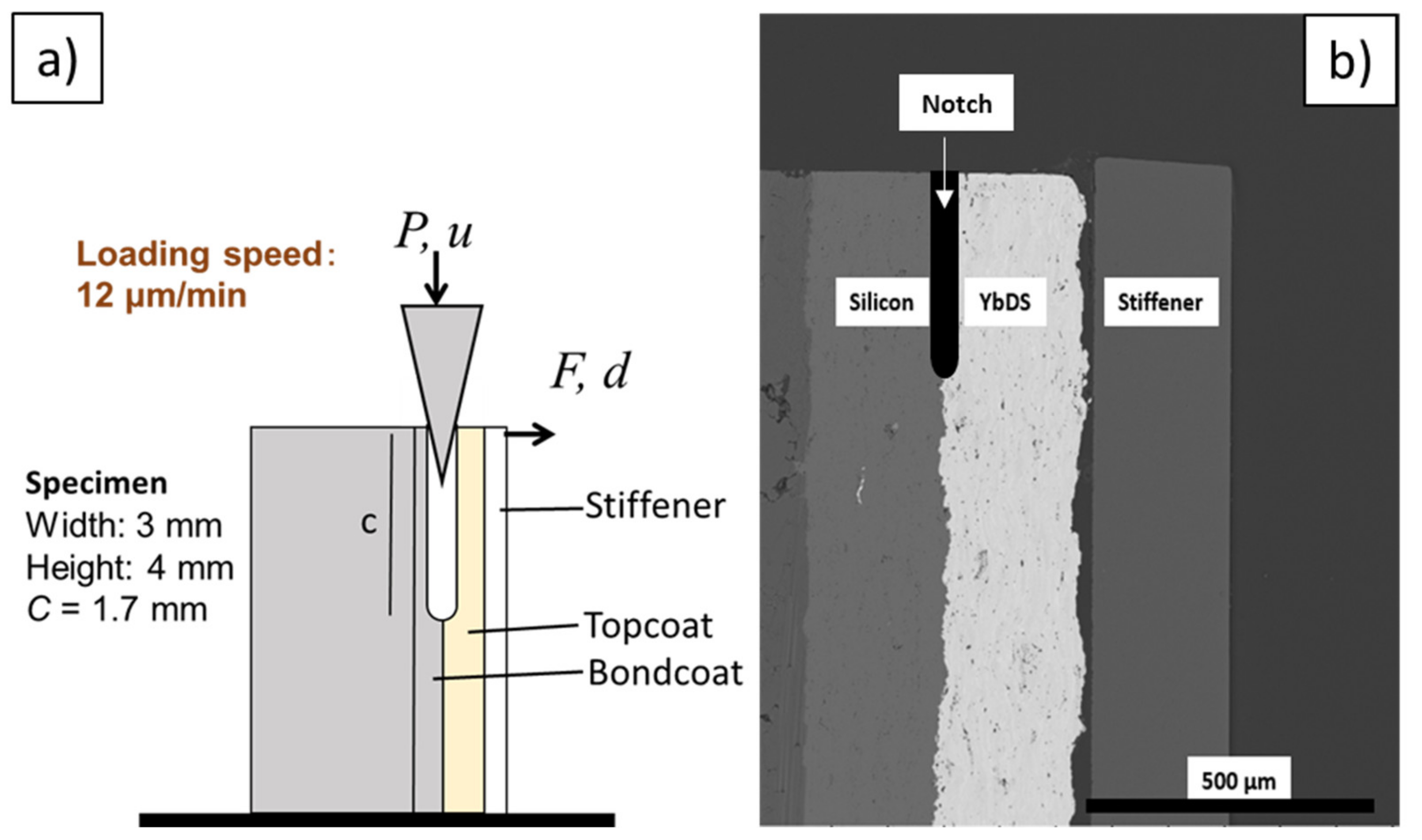
- Kakisawa, H.; Nishimura, T. A method for testing the interface toughness of ceramic environmental barrier coatings (EBCs) on ceramic matrix composites (CMCs). J. Eur. Ceram. Soc. 2018, 38, 655–663. [Google Scholar] [CrossRef]
- Kakisawa, H.; Nishimura, T. A Modified simple interface fracture test for ceramic environmental barrier coating (EBC) on ceramics matrix composite (CMC). J. Ceram. Soc. Jpn. 2018, 38, 655–663. [Google Scholar] [CrossRef]
- Hönig, S.; Süß, F.; Jain, N.; Jemmali, R.; Behrendt, T.; Mainzer, B.; Koch, D. Evaluation of preparation and combustion rig tests of an effusive cooled SiC/SiCN panel. Int. J. Appl. Ceram. Technol. 2020, 139, 325. [Google Scholar] [CrossRef]
- Mainzer, B.; Frie, M.; Jemmali, R.; Koch, D. Development of polyvinylsilazane-derived ceramic matrix composites based on Tyranno SA3 fibers. J. Ceram. Soc. Jpn. 2016, 124, 1035–1041. [Google Scholar] [CrossRef]
- Kawai, E.; Kakisawa, H.; Kubo, A.; Yamaguchi, N.; Yokoi, T.; Akatsu, T.; Kitaoka, S.; Umeno, Y. Crack initiation criteria in EBC under thermal stress. Coatings 2019, 9, 697. [Google Scholar] [CrossRef]
- Qian, B.; Shen, Z. Laser sintering of ceramics. J. Asian Ceram. Soc. 2013, 1, 315–321. [Google Scholar] [CrossRef]
- Ganz, D.; Gasparro, G.; Aegerter, M.A. Laser sintering of SnO2: Sb sol-gel coatings. J. Sol-Gel Sci. Technol. 1998, 13, 961–967. [Google Scholar] [CrossRef]
- Chen, A.-N.; Wu, J.-M.; Liu, K.; Chen, J.-Y.; Xiao, H.; Chen, P.; Li, C.-H.; Shi, Y.-S. High-performance ceramic parts with complex shape prepared by selective laser sintering: A review. Adv. Appl. Ceram. 2018, 117, 100–117. [Google Scholar] [CrossRef]
- He, M.-Y.; Bartlett, A.; Evans, A.G.; Hutchinson, J.W. Kinking of a crack out of an interface: Role of in-plane stress. J. Am. Ceram. Soc. 1991, 74, 767–771. [Google Scholar] [CrossRef]
- Kim, S.-S.; Liu, Y.-F.; Kagawa, Y. Evaluation of interfacial mechanical properties under shear loading in EB-PVD TBCs by the pushout method. Acta Mater. 2007, 55, 3771–3781. [Google Scholar] [CrossRef]
- Kim, W.S.; Lee, J.J. Interfacial fracture toughness measurement and improvement for composite/metal interfaces. ICCM Int. Conf. Compos. Mater. 2009, 222, 1–10. [Google Scholar]


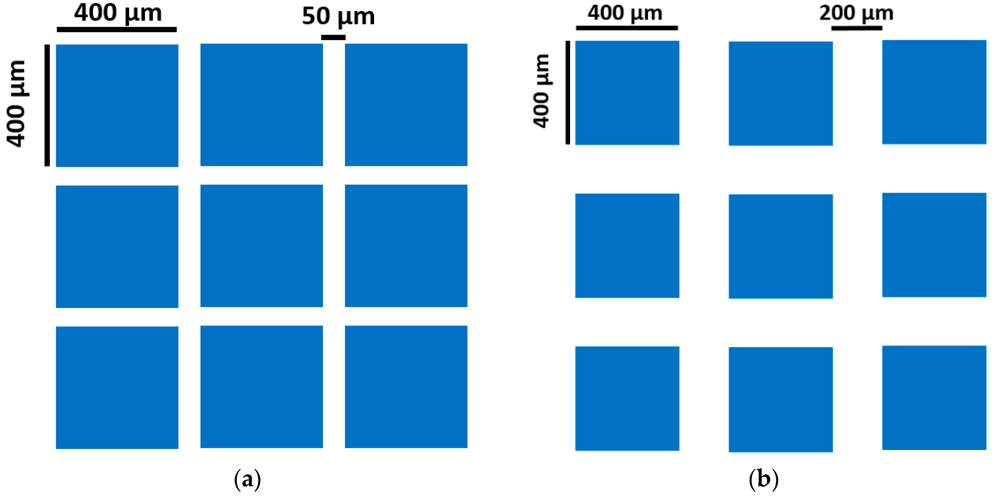
| Pulse Length (ns) | Power (kW) | Frequency (kHz) | Laser Velocity (mm/s) | Spot Diameter (µm) | Line Offset (µm) |
|---|---|---|---|---|---|
| 100 | 12 | 20 | 100 | 40 | 20 |
| Structure | Structure | Rv (µm) | Rz (µm) | Rc (µm) | Ra (µm) |
|---|---|---|---|---|---|
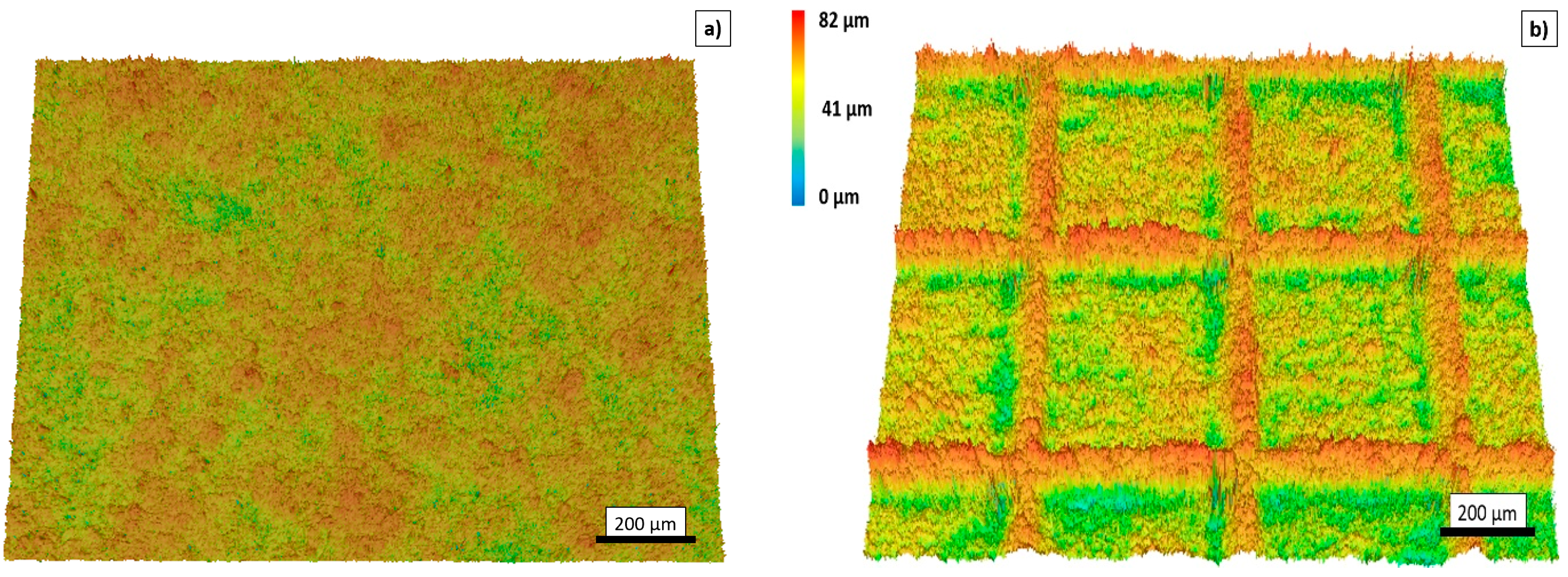
| ST1 | ST1 | 28 | 78 | 43 | 7 |
| ST2 (50 µm) | ST2 (50 µm) | 34 | 82 | 60 | 11 |
| ST3 (200 µm) | ST3 (200 µm) | 56 | 95 | 69 | 10 |
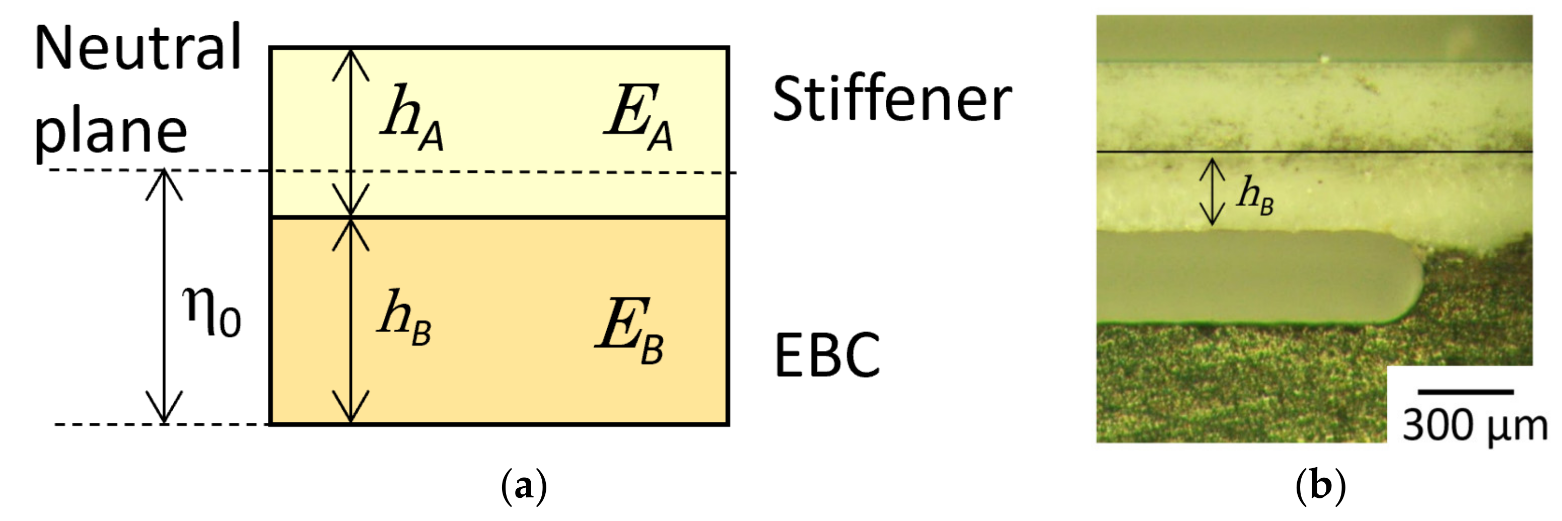
| Sample | hA | hB | η0 | E′I | Load (P) | Length (L) | Interface Toughness (Γ) |
|---|---|---|---|---|---|---|---|
| µm | µm | µm | Nm2 | N | µm | J/m2 | |
| ST1 (Baseline) | 287 ± 23 | 292 ± 21 | 367 ± 14 | 0.01 | 3.59 ± 1.37 | 1900 ± 190 | 8.62 ± 4.7 |
| ST2 (50 µm) | 272 ± 21 | 270 ± 16 | 344 ± 18 | 0.01 | 4.89 ± 0.82 | 1585 ± 88 | 14.7 ± 3.41 |
| ST3 (200 µm) | 271 ± 17 | 262 ± 16 | 337 ± 18 | 0.01 | 4.55 ± 1.09 | 1669 ± 34 | 13.8 ± 5.38 |
Publisher’s Note: MDPI stays neutral with regard to jurisdictional claims in published maps and institutional affiliations. |
© 2021 by the authors. Licensee MDPI, Basel, Switzerland. This article is an open access article distributed under the terms and conditions of the Creative Commons Attribution (CC BY) license (http://creativecommons.org/licenses/by/4.0/).
Share and Cite
Wolf, M.; Kakisawa, H.; Süß, F.; Mack, D.E.; Vaßen, R. Determining Interface Fracture Toughness in Multi Layered Environmental Barrier Coatings with Laser Textured Silicon Bond Coat. Coatings 2021, 11, 55. https://doi.org/10.3390/coatings11010055
Wolf M, Kakisawa H, Süß F, Mack DE, Vaßen R. Determining Interface Fracture Toughness in Multi Layered Environmental Barrier Coatings with Laser Textured Silicon Bond Coat. Coatings. 2021; 11(1):55. https://doi.org/10.3390/coatings11010055
Chicago/Turabian StyleWolf, Markus, Hideki Kakisawa, Fabia Süß, Daniel Emil Mack, and Robert Vaßen. 2021. "Determining Interface Fracture Toughness in Multi Layered Environmental Barrier Coatings with Laser Textured Silicon Bond Coat" Coatings 11, no. 1: 55. https://doi.org/10.3390/coatings11010055
APA StyleWolf, M., Kakisawa, H., Süß, F., Mack, D. E., & Vaßen, R. (2021). Determining Interface Fracture Toughness in Multi Layered Environmental Barrier Coatings with Laser Textured Silicon Bond Coat. Coatings, 11(1), 55. https://doi.org/10.3390/coatings11010055