Article

Morphological Evolution and Interfacial Effects Analysis of Drop Motion in Transverse Vibration of Inclined Plate

Department of Mechanical Engineering, Hangzhou Dianzi University, Hangzhou 310018, China
*
Author to whom correspondence should be addressed.
Coatings 2020, 10(9), 845; https://doi.org/10.3390/coatings10090845
Submission received: 5 July 2020 / Revised: 13 August 2020 / Accepted: 24 August 2020 / Published: 30 August 2020

Abstract

:
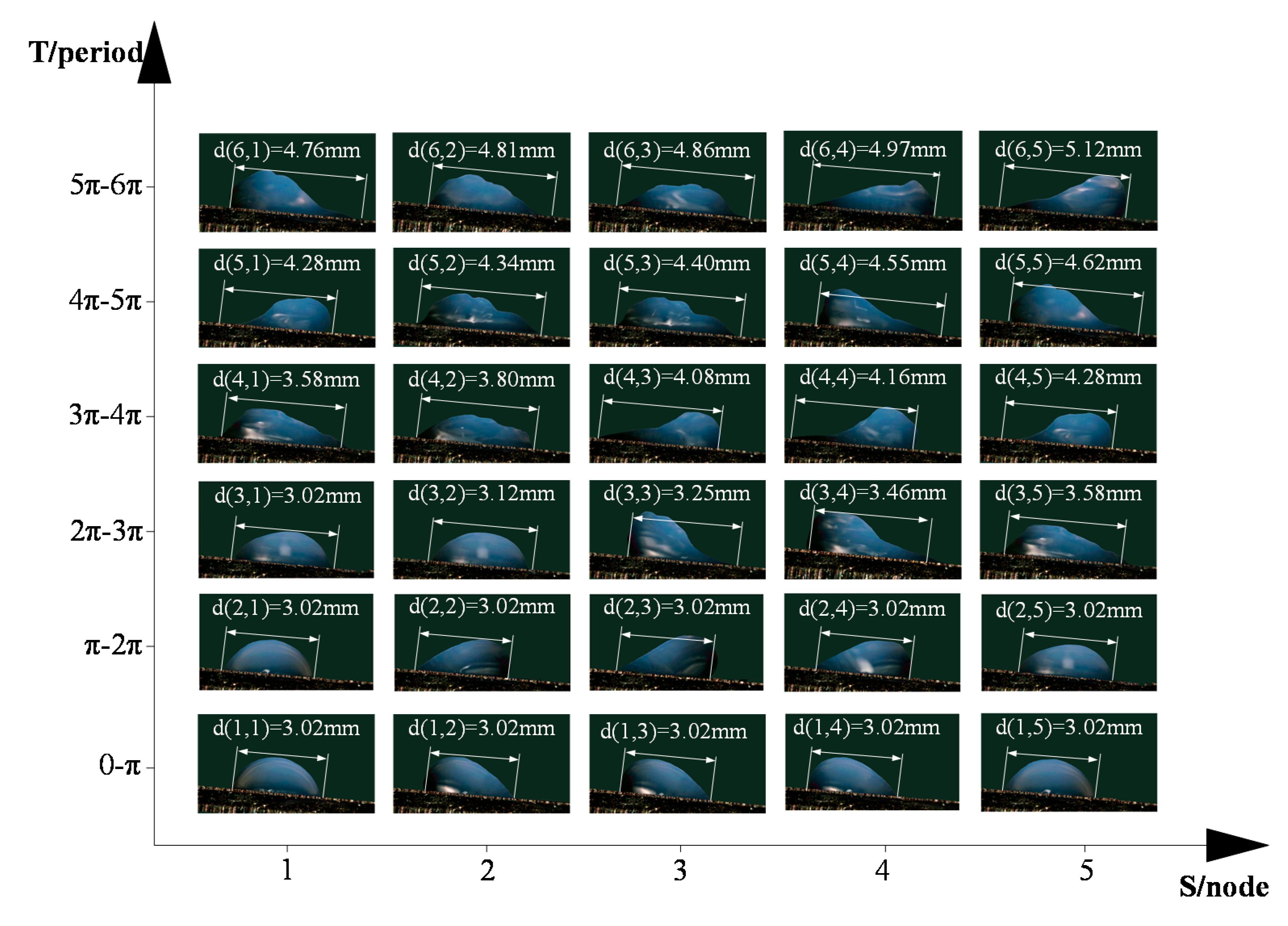
Based on experimental and simulation research, analysis of the morphological evolution and interfacial effects of drop motion in the transverse vibration of inclined micro-textured plate are studied. Experimental results show the morphological evolution of drop involves an oscillation stage, spreading and migration stage, and infiltration stage. The spread diameter increases from the initial 3.02 to 5.12 mm. Meanwhile, based on the real experimental morphology of the drop dynamic wettability, a two-phase flow theoretical model of motion evolution of forced vibration drop was established to simulate the drop spreading process. The analysis result shows the calculated results are close to the experimental results, and the on micro-textured surface is faster spreading coefficient is S-shaped and increases with the increase of time. The spreading velocity than the smooth one, and there is low-speed rotating airflow in the micro-textured pit. The vortex cushion effect and vortex wheel effect are the main reasons for the acceleration of drop motion. Two interfacial effects reduce the friction resistance and impel fluid movement.

1. Introduction

The behavior of drop on the solid surface transient migration and dynamic wetting is widely used in transportation, new energy, aerospace, lubrication, and other fields [1,2]. In the past few decades, people have been working on artificial hydrophobic surfaces to understand the effects of micro- and nano-textures on drop migration. However, the pinning effect causes the liquid to adhere to the fluid-solid interface, the liquid motion on the solid surface is limited. Therefore, how to overcome the drop pinning effect and reduce fluid-solid interface adhesion has become a hot topic in the study of drop motion on solid surfaces.
Vibratory drop dynamics is one of the classical problems in fluid mechanics [3]. Lei et al. [4,5] used loudspeakers as vibration source, and a theory of stripping condensate drop from solid surface was proposed. Boreyko et al. [6] used horn as vibration source to study the viscous effect of drop on the surface of lotus leaves under vibration conditions. Yao et al. [7] found that using low-frequency vibration, it was easier for the drop to overcome the pinning effect when the drop volume was constant. Bormashenko et al. [8] observed the change of wetting mechanism of Cassie-Wenzel state by providing a vertical vibration force on a substrate. Numerous studies have shown that the external energy input of drop can overcome the energy barrier caused from the pinning effect by providing a vibration force on the substrate. This will force the drop to change from a Wenzel to Cassie-Baxter state, eliminating the phenomenon of drop contact angle hysteresis [9,10,11,12].
Meanwhile, reasonable bionic design of surface texture could improve the dynamic characteristics of the fluid-solid interface where the wetting characteristics of the vibration drop on the micro-textured surface are also concerned [13,14,15,16]. Niu, D. et al. [17] had studied the dynamic and static transition of drop on the surface of columnar nanosolids by molecular dynamics simulation. Jia, Z.H. et al. [18] prepared square and circular micro-textured surfaces on polydimethyloxane (PDMS) substrate by photoetching technique to analyze the wetting phenomenon of vibrating drop. Based on the relationship between drop inertia force and adhesion force, Yong, C.J. et al. [19] proposed a prediction model for the wetting process of vibrating drop. Hizumi et al. [20] studied the dynamic wetting of drop and the stress distribution of the contact line. The author of this paper has studied the single-cycle oscillation behavior of drops and the mechanism of elastic wave scattering [21]. Han, Taeyang developed a model to explain the mechanism of the droplet movement and the effects of the wettability of the inner walls of the groove on the droplet movement [22]. Katoh, K. used a photoreactive polymer poly(7-methacryloyloxy coumarin) (PMC) whose molecular structure can be changed reversibly to realize different wettabilities by ultraviolet irradiation [23]. Chowdhury, IU investigated the migration characteristics of liquid drop on hydrophilic and hydrophobic orbits [24]. Wang, Z.L. studied the relationship between surface geometry and contact line pinning [25]. However, none of the related studies involves the motion behavior of vibrating drop on inclined substrate and dynamic modeling and quantitative testing calculation of fluid-solid interface. Little is known about the mechanism of motion evolution and interfacial effect caused between fluid-structure interface.
In view of this, in this study, the micro-textured metal substrate was processed by fiber laser and the drop was driven by vibration force to carry out the transverse transport on of the inclined micro-textured plate. High-speed photography was used to record the morphological evolution of drop in different vibration cycles and the motion mechanism and interfacial effects of drop on the micro-textured surface were revealed. Meanwhile, based on the real experiment morphology of the drop dynamic wettability, the two-phase flow theoretical model of motion evolution of forced vibration drop is established to simulate the spreading process of drop. The relationship between spreading velocity, spreading diameter, spreading coefficient, and time of vibrating drop was quantitatively analyzed. These provided the theoretical basis for eliminating the interfacial effect.

2. Experimental Model

2.1. Experimental Specimens

The topography diagram of the textured stainless steel surface is shown in Figure 1. All samples are made up of Fe, Cr, Ni, Mn, C, and Si. The weight percentage of Fe/Cr/Ni/Mn/C/Si on the testing specimen is 71.5:17.5:7.5:1.5:1.1:0.9, with the elements Fe and Cr being the key constituent elements. The micro-textured square pit length a is 150 μm, the texture spacing b is 150 μm, and the height h is 150 μm.

2.2. Experimental Devices

Figure 2 is a schematic diagram of the experimental device. It consists of a Keyence high-speed camera, variable-frequency control cabinet, computer, micro-injector, and test piece. In the experiment, 4 μL distilled water is dripped steadily onto the micro-textured rough surface through a micro-injector. The vibration is produced by the micro-mechanical vibration test device, and the variable angle table can be adjusted to any desired angle for this experiment. By adjusting the vibration parameters of the inverter control cabin, the periodic surface vibration of the micro-textured surface is generated, and the vibration is transferred to the drop. The sinusoidal waveform is used in the experiment, the amplitude is ±1.5 mm, and the vibration frequency is f = n/60. The vibration frequency is adjusted by motor speed. The motor speed is 1200 r/min so the vibration frequency is 20 Hz. Three force sensors are installed on the vibratory platform to measure the vibration characteristic curve, and the time-domain and frequency-domain curves are obtained to find out whether the vibration source is in accordance with the experimental requirement (the time-domain curve shows that the amplitude and ripple of the experimental vibration show obvious periodic characteristics, the experimental waveform is sinusoidal, and the vibration energy feed is stable. The frequency-domain curve shows that the vibration frequency is around 20 Hz, which is consistent with the experimental plan, which indicates that the vibration source meets the experimental requirements). It is then transferred to the computer through the data acquisition card to store the vibration characteristic curve. The dynamic wetting behavior of vibrating drop was recorded by using Keyence high-speed camera to collect images. It is obtained using an acquisition speed of single-cycle vibration of 230,000 frames per second.

3. Experimental Results and Theoretical Analysis

3.1. Analysis of Experimental Results

In this experiment, the motion patterns of the special time nodes in three cycles of drop is collected. The liquid interacts by vibrational energy, gravitational potential energy, and viscosity energy and Figure 3 shows the transient evolution of drop motion under the condition of 5° declining substrate and 20 Hz vibration frequency. The process consists an oscillation stage, spreading and migration stage, and infiltration stage. The spread diameter increases from the initial 3.02 mm to 5.12 mm, and the motion evolves as follows.
The first stage is the oscillation phase. During the 0–π period, the vibration force is parallel to the ground and moves to the left and the vibration energy begins to input to drop. When the drop is in contact with the micro-textured surface, the surface tension γlv plays a leading role and the component force of the vibration force on the slope overcomes the gravity work. The lowest-layer liquid adheres to the textured surface because of the viscous resistance and the upper liquid of drop tilt towards the direction of the vibration force because of the inertial effect. The advancing contact angle of the drop increases gradually, and the receding contact angle decreases gradually; namely, the contact angle lags behind. In the π–2π period, the vibration force faces to the right. The upper liquid of drop tilts to the right. Due to the fact that the viscous resistance is greater than the resultant force of gravity and vibration, the spreading diameter of drop is always 3.02 mm at this stage. The position of the drop remains the same. The sum of input vibrational energy and drop gravity potential energy is less than the viscous energy. The drop does not exhibit migration behavior but only changes in the surface morphology, showing a tendency of being gentle first and then with steepness along the flow direction.
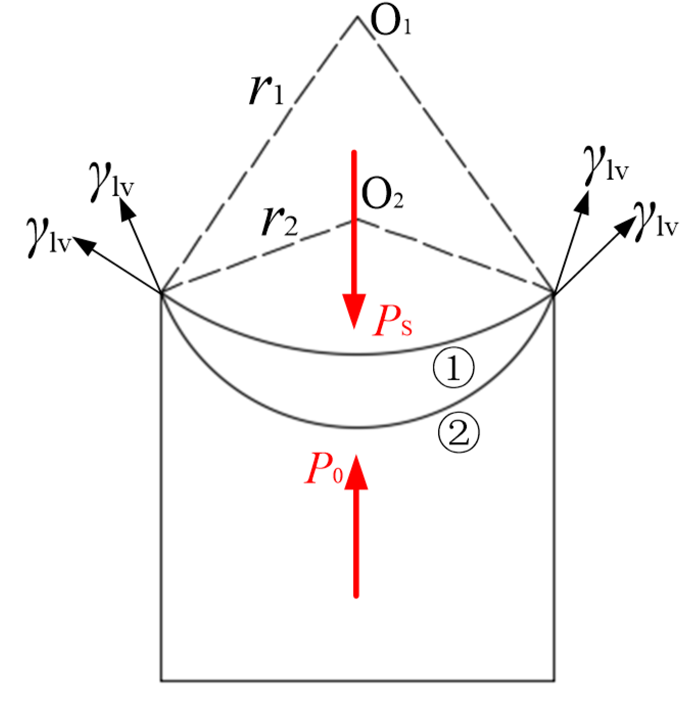
The second stage is the spreading and migration stage. In the 2π–4π period, the bottom liquid gradually enters into the pit. As the contact area between drop and substrate increases, the spread diameter is increasing. Figure 4 shows that when the curvature degree of the liquid surface at the near wall increases from line ① to line ②, the curvature radius of the liquid surface decreases from r1 to r2. According to ΔP = PsP0 = 2γlv/r [26] (where Ps is the internal pressure of drop and P0 is the external pressure of drop. Because the drop is affected by vibration, the pressure inside the drop increases. Vibration causes deformation, which leads to the change of the drop curve radius), when r decreases, the pressure difference ΔP from inside and outside drop increases, which makes the drop gain extra driving force and energy. Then, the drop starts spreading, and the pinning effect of the substrate on drop is enhanced. Compared with the oscillating phase, the drop morphology changes more dramatically in the spreading and migration phase.
In the 2π–3π period, vibration forces parallel to the ground point to the left, and the drop spreads and migrates to the left, overcoming the viscous resistance and gravity. In the 3π–4π period, the vibration forces parallels to the ground point to the right, and drop spreads and migrates to the right, and the drop only needs to overcome viscous resistance, and the gravity does positive work. Oppositely, the gravity plays negative work. Hence, the distance to the right is longer than that of the left. The spreading diameter increases from 3.02 to 4.28 mm. With the continuous superposition of vibration energy, the forced force of drop is greater than the viscous force. The drop overcomes the pinning effect and moves towards the direction of low surface energy. The drop gradually spreads out on the substrate surface and macroscopic migration occurs.
The third stage is the infiltration stage. In the 4π–6π period, the drop infiltrates the micro-texture surface. The solid-liquid-gas three-phase contact line gradually diffuses around the micro-texture surface, the drop shape changes from a flat transition state to a jagged ripple. The more the cycles are extended, the greater the ripple degree. The drop gradually fills the pits and the maximum spreading diameter is reached at 5.12 mm. The spread speed is much faster than the first and second stages. The drop is subjected to repeated stretching and contraction, and the drop radius, surface morphology, and other characteristics are significantly changed.

3.2. Theoretical Analysis

The incline angle α is 5 degrees. The testing drop volume V is 4 μL. The drop radius r is 0.98 mm. The Bond number [27] under this condition is
ρ g r 2 γ l v     0.13   <   1 .
The tension of liquid-gas interfacial γlv is 71.42 × 10⁻³ N/m and the density of water is 996 kg/m3. Since the Bond number is less than 1, gravity can be ignored. However, the author believes that the effect of gravity on the drop exists on the inclined slope, so gravity is still considered in the subsequent analysis.
According to Equations (2)–(5), we can obtain the velocity v ¯ of the substrate. v ¯ = 0.03 m/s. Because the base is a rigid whole, the velocity of any point above is the same.
x = 1 2 a T 2
v = a T
T = 1 f
v ¯ = v 2

4. Numerical Calculation Results and Analysis

Based on the theoretical analysis and experimental results of the movement process of drop on the textured surface (the initial geometric model and data are derived from the actual experimental results), the wetting and migration process of drop is calculated by CFD, and the motion mechanism of drop on the micro-textured surface is further studied. There are three general multiphase models (VOF model, mix model, and Euler model) that can be chosen. The motion model of drop horizontal migration involves drop and air. There is no mass transfer between them, and the motion of drop free surface should be considered emphatically. The VOF model is the most suitable calculation model.

4.1. Governing Equations and Calculation Methods

The VOF model calculates the volume fraction of each control body in the computational domain by calculating the incompatible components. The interpolation method is used to get the boundary between each component, so as to simulate the multi-component flow [28].
The volume fraction of the q component in any unit is determined by Equation (6).
1 ρ q [ t ( α q ρ q )   +   · ( α q ρ q v q ) ]   =   S α q   +   p = 1 n ( m . pq     m . pq )
where m . pq is the mass flow from component q to component p and ρq is the density of component q.
All components in the whole computational domain are derived from the same momentum Equation (7).
t ( ρ v )   +   · ( ρ vv )   =   p   +   · [ μ ( v )   +   v T ]
where ρ is based on controlling the volume fraction of each component in the body and ρ and μ are obtained based on their respective volume fraction.
Considering the influence of surface tension, the CSF (continuum surface force) model proposed by Brackbill [29] is introduced into the equation of momentum as a source term. For two-phase flow
F vol   =   σ ij ρ k i α j 1 2 ( ρ i + ρ j )
where σij is the surface tension coefficient between components and k is the sectional curvature.
The wettability gradient of the wall is set by contact angle, and its action is reflected in the normal direction of the fluid boundary near the wall. The change of the direction of the method line will change the curvature of the interface, thus indirectly affecting the magnitude of the surface tension.
n ˆ = n ˆ w cos θ r   +   t ˆ w sin θ r
where n ˆ w , t ˆ w are the unit normal vector and tangent vector of the wall surface and θr is the forward contact angle.

4.2. Computing Area and Mesh Division

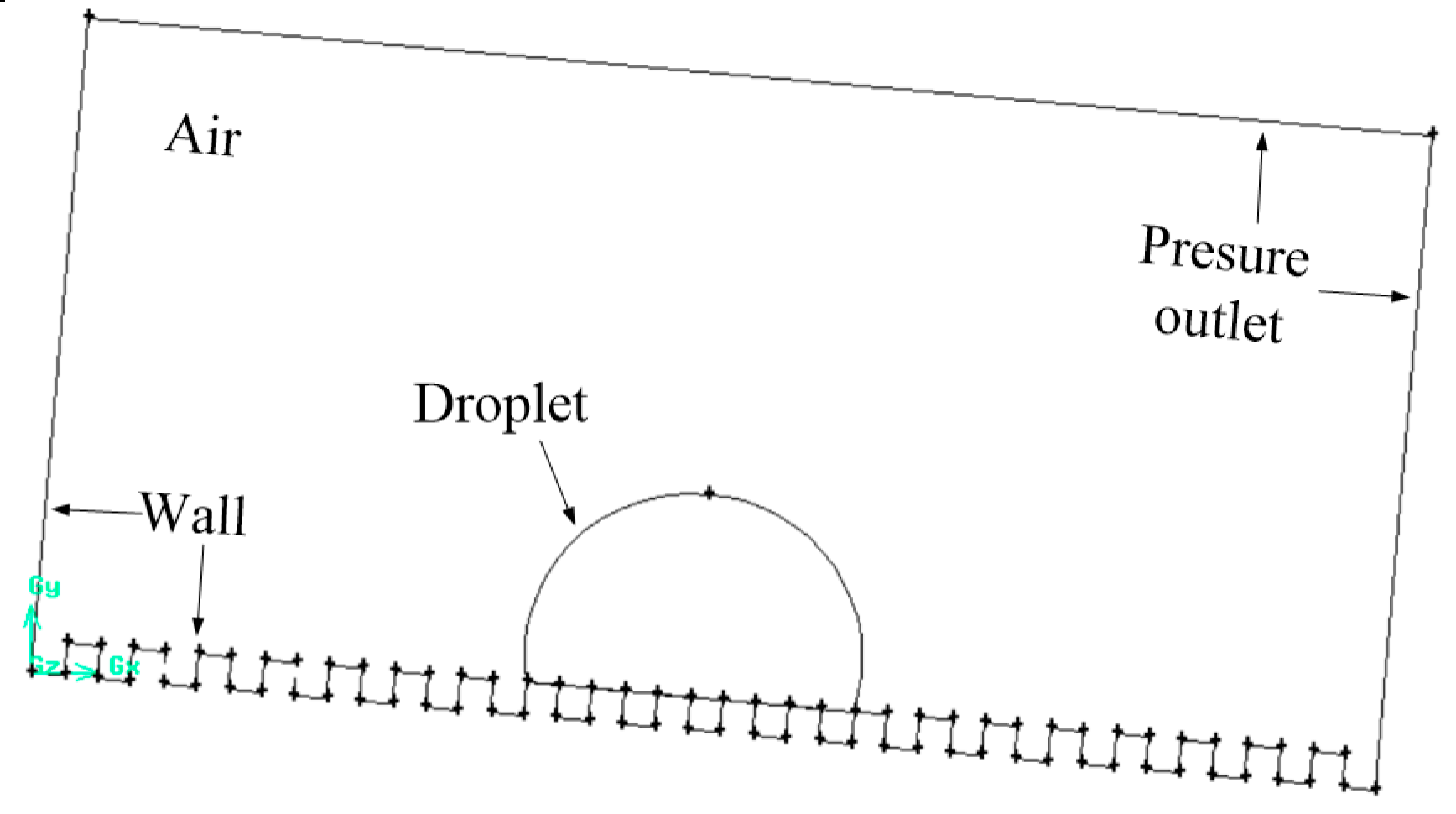
The simulated region is a two-dimensional rectangular (the two-dimensional model is used because it is based on the initial state of the experiment, which represents the state of the plane in the three-dimensional model with the same spreading radius and the same wetting angle) region with a length of 6 mm and a width of 3 mm. The texture size is 150 µm × 150 µm and the texture simulation calculation area is shown in Figure 5. The meshes are triangular unstructured meshes to simulate the gas-liquid-solid interface more accurately. The semicircular drop region grid is locally encrypted and the whole area is composed of 15,608 meshes. The mesh model is shown in Figure 6.

4.3. Boundary Conditions and Initialization

The simulated working medium of three-phase solid-liquid-gas uses 45 steel, water, and air, where water is an incompressible viscous fluid. The density is 996 kg/m3, viscosity is 0.001 Pa·s, surface tension γlv is 0.072 N/m, and gravity acceleration g is 9.8 m/s2. In the numerical model, the initial radius r of drop is 0.98 mm and the initial velocity v ¯ of the substrate is 30 mm/s. The drop is discretized by drawing point method and the surface of the experimental drop is replaced approximately by the curved surface of the node, and the micro-deformation of the free surface is realized by the virtual displacement of the node. The boundary of the calculated area includes the boundary of atmosphere and the boundary of base. The atmospheric boundary is defined as ordinary pressure boundary, the top and lateral boundaries are atmospheric boundaries, and the volume fraction of the second phase is defined as 0, that is, the air phase is always in the top and the surrounding region, and the bottom of the model is a non-slip 45 steel wall.
The physical model of the drop moving on the micro-textured surface is as follows. Considering the drop is in an infinite atmosphere, it is placed on the inclined experimental substrate. The drop is hemispherical and incompressible in the initial state. The initial velocity of drop is 0.03 m/s, and it starts to move under the action of gravity and vibration. The pressure at infinity is a standard atmospheric pressure.

4.4. Calculation Results

Figure 7 is the motion process of the vibrating drop along the inclined wall when the direction of vibration is horizontal to the right under a single cycle, and the drop volume diagram shows the numerical results are close to the experimental results. When the vibration force is horizontally facing to the right, the drop deviates from the initial position, the spreading diameter increases, and the drop shape changes greatly with the increase of time t. When t = 12 ms, the direction of vibration force is right, the vibration force is opposite to the direction of gravity along the surface of the substrate, and the component force of gravity places negative work on drop while the position of the drop is not changed; only the shape is slightly deformed and the upper half of the drop tilts to the left. When t = 18 ms, the liquid which is closest to the substrate enters the interior of the micro-texture, the diameter of solid-liquid contact increases. When t = 24 ms, the upper drop is gradually tilted from left to right, and the lower drop spreads to the right on the inclined surface. When t = 36 ms, the vibration force is zero, but the drop is still migrating and spreading down the slope due to inertia. As the iteration proceeds, the drop spreads into a stable equilibrium stage and no longer migrates. The spreading rate of drop gradually slows down, and eventually spreads around the drop at a constant speed and infiltrates into the textured surface.
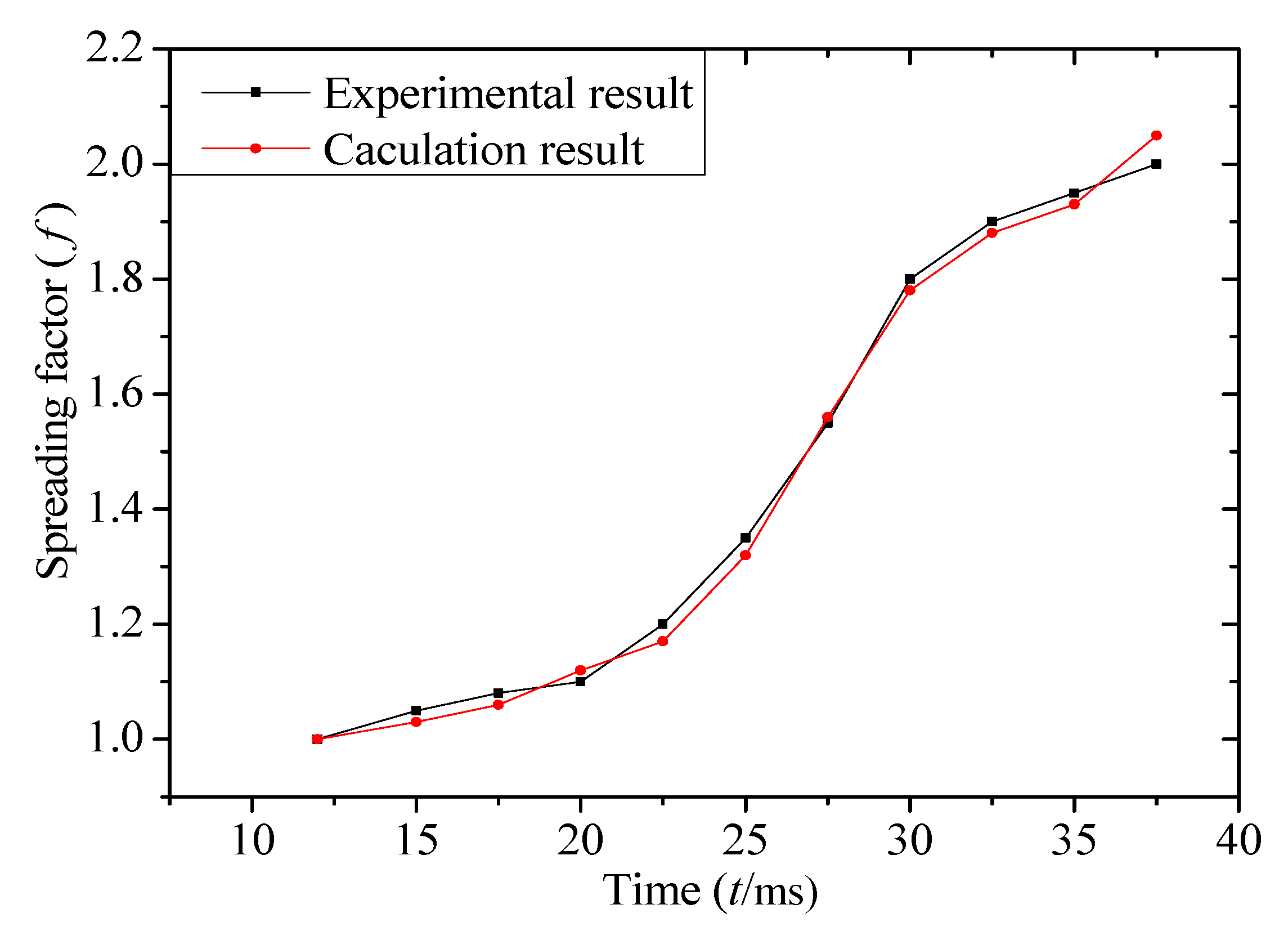
In order to further analyze the spreading state of vibratory drop in motion, the spreading coefficient f (f = d/d0) is introduced, where d is the spreading diameter of drop at any time, and d0 is the spreading diameter of drop at the initial moment. Figure 8 shows the relationship between drop spreading coefficient f and time t. The results show that the calculated results are in good agreement with the experimental results and the maximum error of spreading coefficient is less than 0.05. VOF calculation method can be used to calculate migration processes of similar drop. The spreading coefficient f assumes S-shape curve and increases with the increase of time t. When t < 20 ms, the slope of the spreading diameter curve is small, and f increases slowly. When 20 ms ≤ t ≤ 30 ms, the velocity of drop spreading increases rapidly, and when t > 30 ms, the growth rate of spreading coefficient slows down.
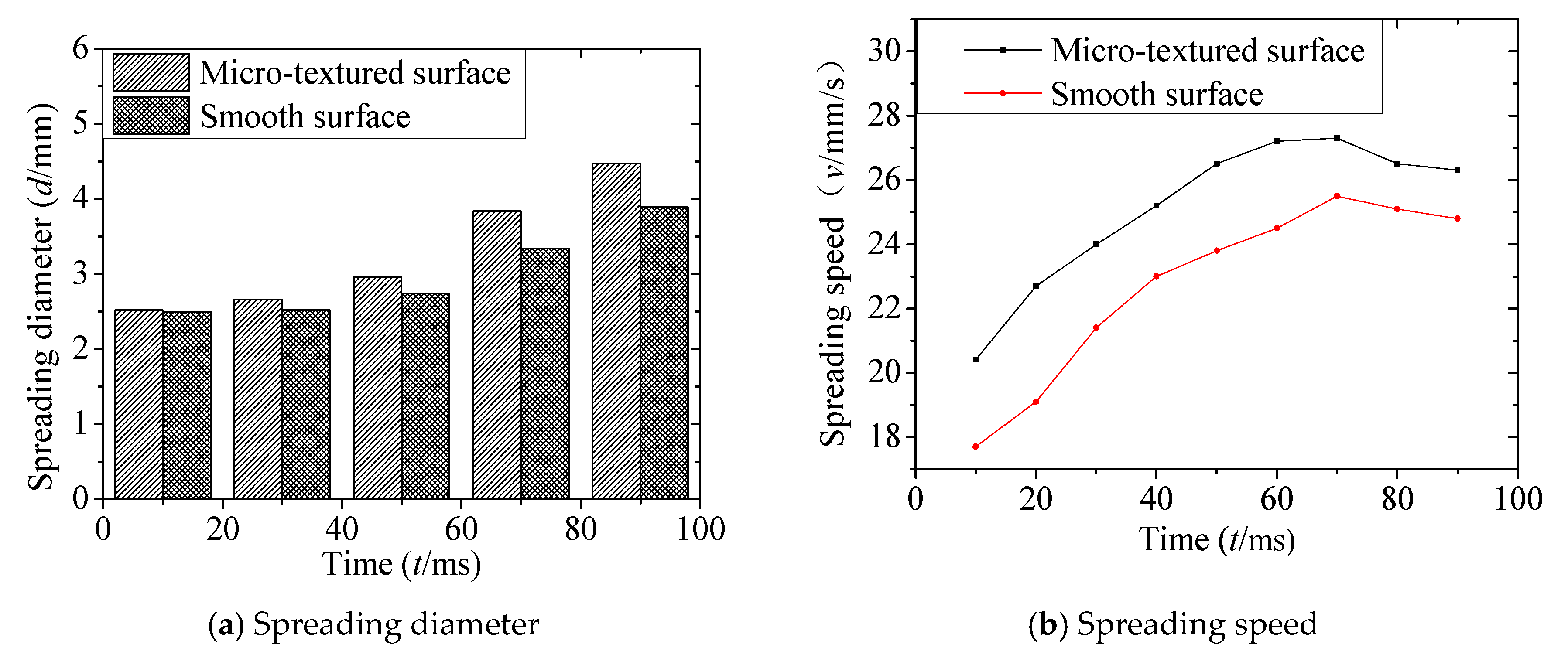
Figure 9 and Figure 10 show the motion morphology, spreading diameter, and spreading velocity of the vibrating drop on textured and smooth surface. Results show the vibratory drop gradually spreads out on the textured surface and smooth surface with the increase of time t. The spreading velocity of micro-textured surface is higher than the smooth surface, and the difference is between 2.3 mm/s and 3.6 mm/s. When t < 20 ms, the spreading diameter on the textured surface is similar with smooth one, which is about 2.5 mm. With the increase of time t, the spreading radius on textured surface is larger than that on the smooth surface, and the gap is 0.65 mm. The state of the drop in Figure 9 is different from that in Figure 2 because Figure 2 refers to the conversion of the drop from the Cassie state under initial contact to the Wenzel state after vibration, which is a process of wetting state transition.
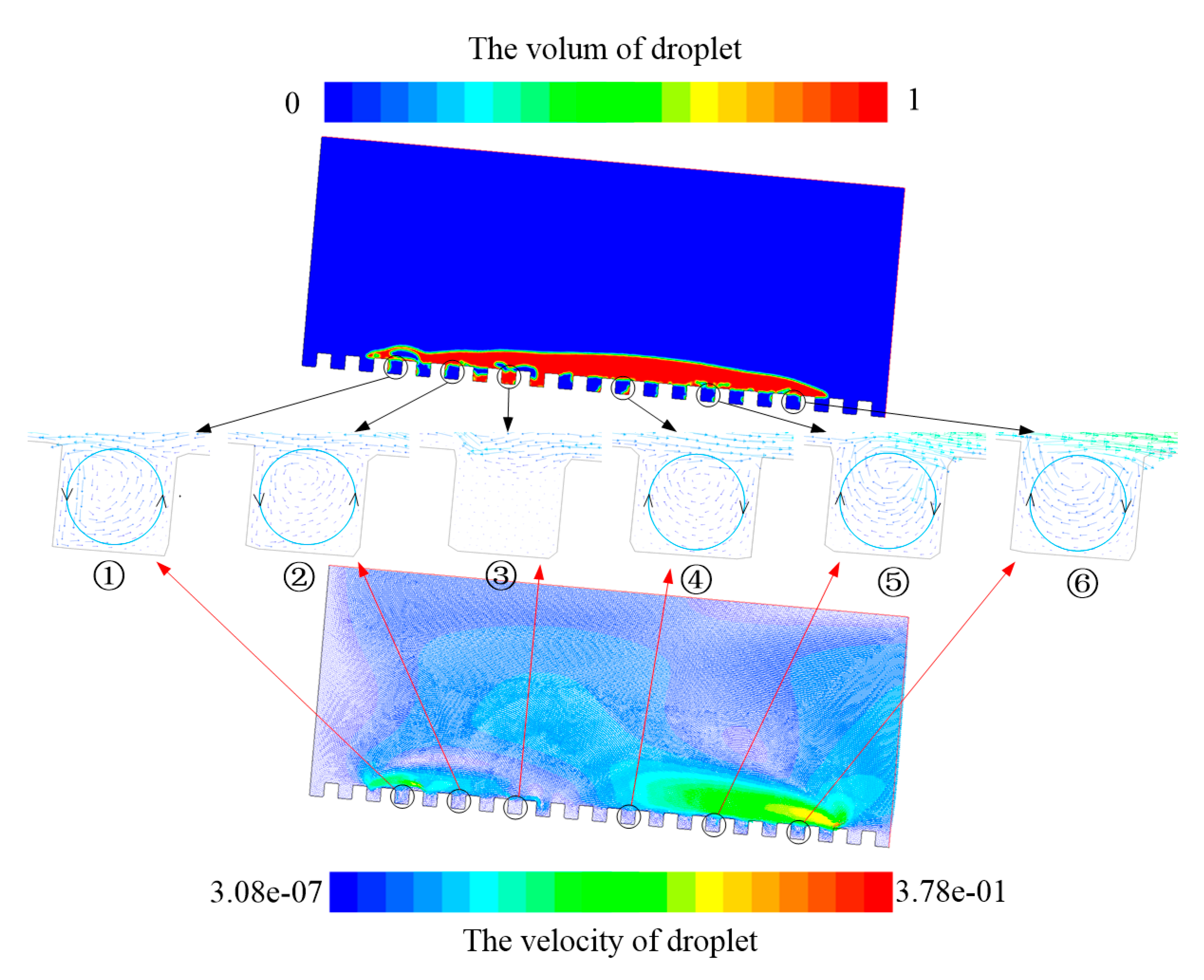
In order to reveal the motion mechanism and interfacial effects of drop on the micro-textured surface, the volume and velocity vector diagram of drop moving to 75 ms were analyzed. Local amplification of six pits is carried out to study the gas motion and effects which is inside the pit, as shown in Figure 11. Results show that there is low-speed swirling airflow which is inside the pit. The direction of the airflow in pit ① and pit ② is counterclockwise rotation, and the upper liquid moves to the left. The upper fluid of pit ③ is at the junction of the left and right fluid. The velocity of the fluid at the junction is very small, and more liquid seeps into pit ③. There is only a small amount of gas that cannot form a rotating flow. The airflow of pit ④, pit ⑤, and pit ⑥ rotates clockwise and the upper liquid moves to the right. Therefore, the rotating airflow which is inside the pit can produce a double effect.

4.4.1. Vortex Cushion Effect

Figure 12 shows that the velocity of current Vl is 0.027 m/s and the velocity of rotating airflow Va is 0.014 m/s. The low-speed rotating airflow causes gas-liquid contact between the inner airflow and the external current of the pit, which forms a vortex cushion effect. It makes the velocity gradient between high-speed current and low-speed airflow smaller, and the airflow velocity in the pit and overflow pit along the liquid flow direction is lower. The pulsation intensity in the near-wall region is reduced, and the loss of pulsation energy is also reduced accordingly. For a short period of time, the liquid could not penetrate into the pit, and the friction resistance between the drop and the textured surface was reduced.

4.4.2. Vortex Wheel Effect

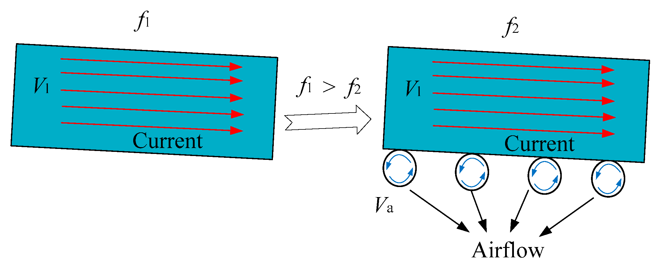
Figure 11 and Figure 12 show there are many vortexes in the pits, and those vortexes have specific rotation directions which are influenced by pits. The current flow is limited by the three sides of the pit and generates additional power which makes the current flow over the rotating airflow in the pit, which can be called the vortex wheel effect. The rotating airflow is similar to the role of the rolling bearing. The sliding friction state between the gas-liquid interface is transformed into the rolling friction state, and the sliding friction coefficient f1 is larger than the rolling friction coefficient f2, see Figure 13. The friction resistance of the fluid is reduced, which weakens the pinning effect of drop on the textured surface and impels fluid movement.
The vortex cushion effect and vortex wheel effect are the main determinants of the speed of drop movement.

5. Conclusions

Based on experimental and simulation research, analysis of the morphological evolution and interfacial effects of drop motion in the transverse vibration of inclined micro-textured plate are studied.
(1)
The experimental results show the morphological evolution of drop involves an oscillation stage, spreading and migration stage, and infiltration stage in the transverse vibration of inclined micro-textured plate with the continuous input of vibration energy, and the surface shape of the drop changes from a flat transition state to a jagged ripple. The drop spreading diameter changes from the initial 3.02 mm to 5.12 mm.
(2)
Based on drop motion mechanism, a two-phase flow theoretical model of motion evolution of forced vibration drop is established. The calculated results are close to the experimental results and the maximum error of spreading coefficient is less than 0.05, f is S-shaped and increases with the increase of time t. When t < 20 ms, the spreading coefficient increases slowly. When 20 ms ≤ t ≤ 30 ms, the velocity of drop spreading is accelerated rapidly. When t > 30 ms, the growth rate of spreading coefficient slows down.
(3)
The motion of vibrating drop on smooth and textured surface was simulated. The spreading velocity on a micro-textured surface is faster than for a smooth surface, and there is low-speed rotating airflow inside the micro-textured pit. The vortex cushion effect and vortex wheel effect are the main reasons for the acceleration of drop motion. Two interfacial effect reduce the friction resistance of the fluid, weaken the pinning effect of the textured surface to drop, and impel fluid movement.

Author Contributions

Conceptualization, J.X. Data curation, J.M. Formal analysis, J.N. Funding acquisition, S.F. Investigation, L.Z. Methodology, R.W. All authors have read and agreed to the published version of the manuscript.

Funding

This research was funded by the Nature Science Foundation of Zhejiang Province, China (No. LY19E050011, LGF18E060001), the National Nature Science Foundation of China (No.51775153).

Conflicts of Interest

The authors declare no conflict of interest.

References

  1. Hu, H.; Huang, S.; Chen, L. Displacement of liquid droplets on micro-grooved surfaces with air flow. Exp. Therm. Fluid Sci. 2013, 49, 86–93. [Google Scholar] [CrossRef]
  2. Liang, Y.; Shu, L.; Natsu, W.; He, F. Anisotropic wetting characteristics versus roughness on machined surfaces of hydrophilic and hydrophobic materials. Appl. Surf. Sci. 2015, 331, 41–49. [Google Scholar] [CrossRef]
  3. Savva, N.; Kalliadasis, S. Low-frequency vibrations of two-dimensional droplets on heterogeneous substrates. J. Fluid Mech. 2014, 754, 515–549. [Google Scholar] [CrossRef] [Green Version]
  4. Lei, W.; Jia, Z.; He, J.; Cai, T. Dynamic properties of vibrated drops on a superhydrophobic patterned surface. Appl. Therm. Eng. 2014, 62, 507–512. [Google Scholar] [CrossRef]
  5. Noblin, X.; Buguin, A.; Brochard-Wyart, F. Vibrated sessile drops: Transition between pinned and mobile contact line oscillations. Eur. Phys. J. E 2004, 14, 395–404. [Google Scholar] [CrossRef] [PubMed]
  6. Boreyko, J.B.; Chen, C.H. Restoring superhydrophobicity of lotus leaves with vibration-induced dewetting. Phys. Rev. Lett. 2009, 103, 174502. [Google Scholar] [CrossRef] [PubMed] [Green Version]
  7. Yao, C.; Lai, C.; Alvarado, J.L.; Zhou, J.; Aung, K.T.; Mejia, J.E. Experimental study on effect of surface vibration on micro textured surfaces with hydrophobic and hydrophilic materials. Appl. Surf. Sci. 2017, 412, 45–51. [Google Scholar] [CrossRef]
  8. Bormashenko, E.; Pogreb, R.; Whyman, G.; Erlich, M. Cassie−Wenzel Wetting Transition in Vibrating Drops Deposited on Rough Surfaces:  Is the Dynamic Cassie−Wenzel Wetting Transition a 2D or 1D Affair. Langmuir ACS J. Surf. Colloids 2007, 23, 6501. [Google Scholar] [CrossRef]
  9. Rahimzadeh, A.; Eslamian, M. Experimental study on the evaporation of sessile droplets excited by vertical and horizontal ultrasonic vibration. Int. J. Heat Mass Transf. 2017, 114, 786–795. [Google Scholar] [CrossRef]
  10. Jia, Z.H.; Lei, W.; Yang, H.N.; Wang, G. Dynamic Wetting Behavior of Vibrated Droplets on a Micropillared Surface. Adv. Mater. Sci. Eng. 2016, 2016, 8409683. [Google Scholar] [CrossRef] [Green Version]
  11. Jia, Z.; Lei, W.; He, J.; Cai, T. Vibration-induced Wenzel-Cassie wetting transition on rough patterned surface. Ciesc J. 2014, 65, 544–549. [Google Scholar]
  12. Whitehill, J.; Neild, A.; Ng, T.; Martyn, S.; Chong, J. Droplet spreading using flow frequency vibration. Appl. Phys. Lett. 2011, 98, 133503. [Google Scholar] [CrossRef]
  13. Bottiglione, F.; Mundo, R.D.; Soria, L.; Carbone, G. Wenzel to Cassie Transition in Superhydrophobic Randomly Rough Surfaces. Nanosci. Nanotechnol. Lett. 2015, 7, 74–78. [Google Scholar] [CrossRef]
  14. Bormashenko, E.; Pogreb, R.; Stein, T.; Whyman, G.; Erlich, M.; Musin, A.; Machavariani, V.; Aurbach, D. Characterization of rough surfaces with vibrated drops. Phys. Chem. Chem. Phys. PCCP 2008, 10, 4056. [Google Scholar] [CrossRef] [PubMed]
  15. Kou, J.L.; Lu, H.J.; Wu, F.M.; Fan, J. Toward the hydrophobic state transition by the appropriate vibration of substrate. EPL 2011, 96, 56008. [Google Scholar] [CrossRef]
  16. Yamada, T.; Sakai, K. Observation of rapid wetting behavior by analysis of microdroplet vibration on solid surface. IEICE Tech. Rep. 2009, 109, 9–12. [Google Scholar]
  17. Niu, D.; Tang, G.H. Static and dynamic behavior of water droplet on solid surfaces with pillar-type nanostructures from molecular dynamics simulation. Int. J. Heat Mass Transf. 2014, 79, 647–654. [Google Scholar] [CrossRef]
  18. Jia, Z.H.; Lei, W.; Ji-Chang, H.E.; Cai, T.M. Transition of Wetting State for Vibrated Droplets on Rough Surfaces. J. Chem. Eng. Chin. Univ. 2015, 29, 58–63. [Google Scholar]
  19. Jung, Y.C.; Bhushan, B. Dynamic Effects Induced Transition of Droplets on Biomimetic Superhydrophobic Surfaces. Langmuir 2009, 25, 9208–9218. [Google Scholar] [CrossRef]
  20. Hizumi, Y.; Omori, T.; Nishida, S.; Yamaguchi, K.; Kajima, Y.; Yuka, H. Study on the Flow in a Droplet under Dynamic Wetting and the Stress Tensor Distribution in the Vicinity of the Contact Line by Means of Molecular Dynamics Simulation(Selected Researches in CFD27). J. Jpn. Soc. Fluid Mech. 2014, 33, 103–110. [Google Scholar]
  21. Xu, J.; Li, B.; Zhou, C.; Xiao, J.; Ni, J. The relationship study between texture vibrating plate dynamic wettability and elastic wave scattering. Appl. Surf. Sci. 2017, 409, 208–213. [Google Scholar] [CrossRef]
  22. Han, T.; Noh, H.; Park, H.S.; Kim, M.H. Effects of wettability on droplet movement in a V-shaped groove. Sci. Rep. 2018, 8, 1–10. [Google Scholar] [CrossRef] [Green Version]
  23. Katoh, K.; Tamura, H.; Sato, E.; Wakimoto, T. Control of droplet movement on an inclined wall with sawtoothed wettability pattern by applying ultrasonic vibration. Exp. Fluids 2018, 59. [Google Scholar] [CrossRef] [Green Version]
  24. Chowdhury, I.U.; Mahapatra, P.S.; Sen, K.A. Self-driven droplet transport: Effect of wettability gradient and confinement. Phys. Fluids 2019, 31. [Google Scholar] [CrossRef]
  25. Wang, Z.; Lin, K.; Zhao, Y. The effect of sharp solid edges on the droplet wettability. J. Colloid Interface Sci. 2019, 563–571. [Google Scholar] [CrossRef] [PubMed]
  26. Barkley, S.; Scarfe, S.J.; Weeks, E.R.; Dalnoki-Veress, K. Predicting the size of droplets produced through Laplace pressure induced snap-off. Soft Matter 2016, 12. [Google Scholar] [CrossRef] [PubMed] [Green Version]
  27. Zhao, Y.P. Physical Mechanics of Surfaces and Interfaces; The Science Publishing Company: Beijing, China, 2012; pp. 121–124, 249–255. [Google Scholar]
  28. Mai, Y.B.; Yu-Hang, F.U.; Yang, F. Numerical Simulation of Droplet Movement on a Horizontal Wettability Gradient Surface. Value Eng. 2016, 35, 209–211. [Google Scholar]
  29. Brackbill, J.U.; Kothe, D.B.; Zemach, C. A Continuum Method for Modeling Surface Tension. J. Comp. Phys. 1992, 100, 335–354. [Google Scholar] [CrossRef]
Figure 1. Schematic view of micro-textured surface, (a) Schematic diagram of the model of texture size; (b) Schematic diagram of the actual topographic map.
Coatings 10 00845 g001
Figure 2. Schematic diagram of experimental apparatus.
Coatings 10 00845 g002
Figure 3. Transient evolution of vibrating drop in three periods on textured surfaces.
Coatings 10 00845 g003
Figure 4. Diagram of drop curvature change in texture.
Coatings 10 00845 g004
Figure 5. Model schematic diagram.
Coatings 10 00845 g005
Figure 6. Grid diagram.
Coatings 10 00845 g006
Figure 7. Experimental and CFD calculation results of vibrating drop motion in a single period.
Coatings 10 00845 g007
Figure 8. Drop spreading coefficient varying with time t.
Coatings 10 00845 g008
Figure 9. Motion evolution of drop on textured and smooth surfaces.
Coatings 10 00845 g009
Figure 10. Spread diameter and velocity of drop on micro-textured and smooth surfaces over time.
Coatings 10 00845 g010
Figure 11. Schematic diagram of the pit air vortex.
Coatings 10 00845 g011
Figure 12. Schematic diagram of vortex cushion effect.
Coatings 10 00845 g012
Figure 13. Schematic diagram of vortex wheel effect.
Coatings 10 00845 g013