Article

Mechanical Investigations of ASTM A36 Welded Steels with Stainless Steel Cladding

by
Pavaret Preedawiphat
1,
Numpon Mahayotsanun
1,*,
Keerati Sa-ngoen
2,
Mai Noipitak
3,
Pongsak Tuengsook
4,
Sedthawatt Sucharitpwatskul
5 and
Kuniaki Dohda
6
1
Department of Mechanical Engineering, Faculty of Engineering, Khon Kaen University, 123 Moo 16 Mittraphap Rd., Nai-Muang, Muang, Khon Kaen 40002, Thailand
2
LPN Metallurgical Research Center (LPNMRC), 299 Moo 2, Naiklongbangplakod, Prasamutjedee, Samutprakarn 10290, Thailand
3
Materials and Nondestructive Testing Laboratory, Ratchaburi Learning Park, Office of the President, King Mongkut’s University of Technology Thonburi, Pracha Uthit Rd, Bang Mot, Thung Khru, Bangkok 10140, Thailand
4
Department of Production Engineering, Faculty of Engineering, King Mongkut’s University of Technology, Thonburi 10140, Thailand
5
National Metal and Materials Technology Center (MTEC), National Science and Technology Development Agency (NSTDA), Pathum Thani 12120, Thailand
6
Department of Mechanical Engineering, Northwestern University, 2145 Sheridan Road, Evanston, IL 60208, USA
*
Author to whom correspondence should be addressed.
Coatings 2020, 10(9), 844; https://doi.org/10.3390/coatings10090844
Submission received: 1 July 2020 / Revised: 24 August 2020 / Accepted: 27 August 2020 / Published: 30 August 2020
(This article belongs to the Special Issue Surface Engineering for Friction and Wear Reduction)

Abstract

:
The in-service life of ASTM A36 welded steel pipes in power plants is often shortened by ash corrosion. During the heating condition, the ash deposition on the welded steel pipes gradually reduces the thickness of the pipes, thus, reducing the lifetime. Instead of replacing the pipes with new ones, the cost could be significantly reduced if the lifetime could be further extended. Weld cladding was the method selected in this study to temporarily extend the service life of welded pipes. This paper performed the mechanical investigations of A36—A36 welded steel plates after coating the surfaces with 309L stainless steel with a cladding method. The residual stress was also tested to observe the internal stresses developed during the welding processes of A36—A36 specimens. The comparison between the coated and non-coated surfaces of welded steels was performed by using the tensile tests (at room and elevated temperatures), corrosion (pitting corrosion, intergranular corrosion, and weight-loss corrosion) tests, and wear (shot blasting) tests. The life-extension of both coatings was evaluated based on the tensile tests and the corrosion and wear tests provided the qualitative evaluations of the coating performance. The results showed that surfaces coated by cladding could be used to temporarily extend the life of ASTM A36 welded steel under the studied conditions.

1. Introduction

ASTM A36 is a carbon structural steel generally used in welded constructions and power plants [1]. In coal-fired and biogas power plants, ash can deposit on steel surfaces and cause severe corrosion [2,3]. Under cyclic thermal conditions coupled with ash corrosion, the lifetime of these structural components is significantly reduced [4], and one of the main reasons is the thickness reduction or weight loss on steel surfaces [5]. The corrosion consequences can lead to component failures, safety and environment hazards, downtime, and high maintenance costs. One of the standard techniques to prevent such failures or extend the lifetime is surface coating [6]. Stainless steels have been widely coated on their surfaces in many applications and conditions due to the resulting superior microstructural and mechanical properties [7,8,9,10,11,12,13,14,15,16].
The process of bonding stainless steels on steel surfaces is called cladding, which can be carried out by using welding or hard facing [17,18,19,20,21,22], laser cladding [23,24,25,26,27,28,29,30], and rolling [31]. The performance of these cladding coatings is highly influenced by the microstructures and alloys of the surfacing materials [32,33,34,35]. In general, these coated surfaces provide wear resistance characteristics [36,37,38,39,40,41,42,43]. They are also commonly exposed to the systems having both mechanical and corrosion wear phenomena [44,45,46,47,48]. Most importantly, they must operate at elevated temperatures for a long time without thermal fatigue [49] and creep [50] failures.
Since many structural components in power plants are welded together, the stainless steel cladding overlays on welded steel joints is a significant concern and must be well understood [51]. One research study found that a two-layer weld overlay was recommended to achieve better corrosion resistance [52]. Different overlay coatings and processes were also investigated to observe the interface bonding metallurgy and strengths [53]. Hardness and tensile tests were also performed to observe the stainless steel coating on steel welds [54]. Nevertheless, it is still unclear if welded steel joints overlayed with stainless steel coatings would survive and perform under the operating conditions. This study aimed to investigate the mechanical properties of the stainless steel cladding surfaces of steel welds. Note that purpose of the addition of cladding was only to temporarily extend the lifetime of the welded components, which could significantly save power plants’ downtime costs. However, the coated surfaces must also work under the required conditions without failures. As a result, tensile tests were carried to observe the bonding interfaces’ strengths at room and elevated temperatures. Corrosion and wear tests were also performed to determine if these cladding surfaces could withstand corrosive environments.

2. Materials and Methods

2.1. Weld Materials Preparation

The scope of this research was to investigate the extended lifetime of the A36—A36 welded joint by coating its surface by cladding it with 309L stainless steel. The substrate workpiece was prepared by welding two ASTM A36 plates together, as shown in Figure 1.
Before welding, two A36 plates were pre-heated at 148 °C to avoid recrystallization, which could lead to hydrogen-induced cracking. The first two layers were welded by gas tungsten arc welding (GTAW) with 99.9% argon shielding gas, and layers 3 to 13 were joined by using shielded metal arc welding (SMAW). Note that the weld groove angle in the SMAW process was 75° with a 3 mm root height and a 3 mm root gap. The specific conditions of the two welding processes are listed in Table 1. The chemical and mechanical properties of the substrate and filler materials used in the welding processes are described in Table 2 and Table 3, respectively.
The welded plate’s macrostructure was then examined to determine the weld quality, as illustrated in Figure 2. Three main zones could be observed in the cross-section of the A36—A36 weldment: base, heat affected zone (HAZ), and weld metal.

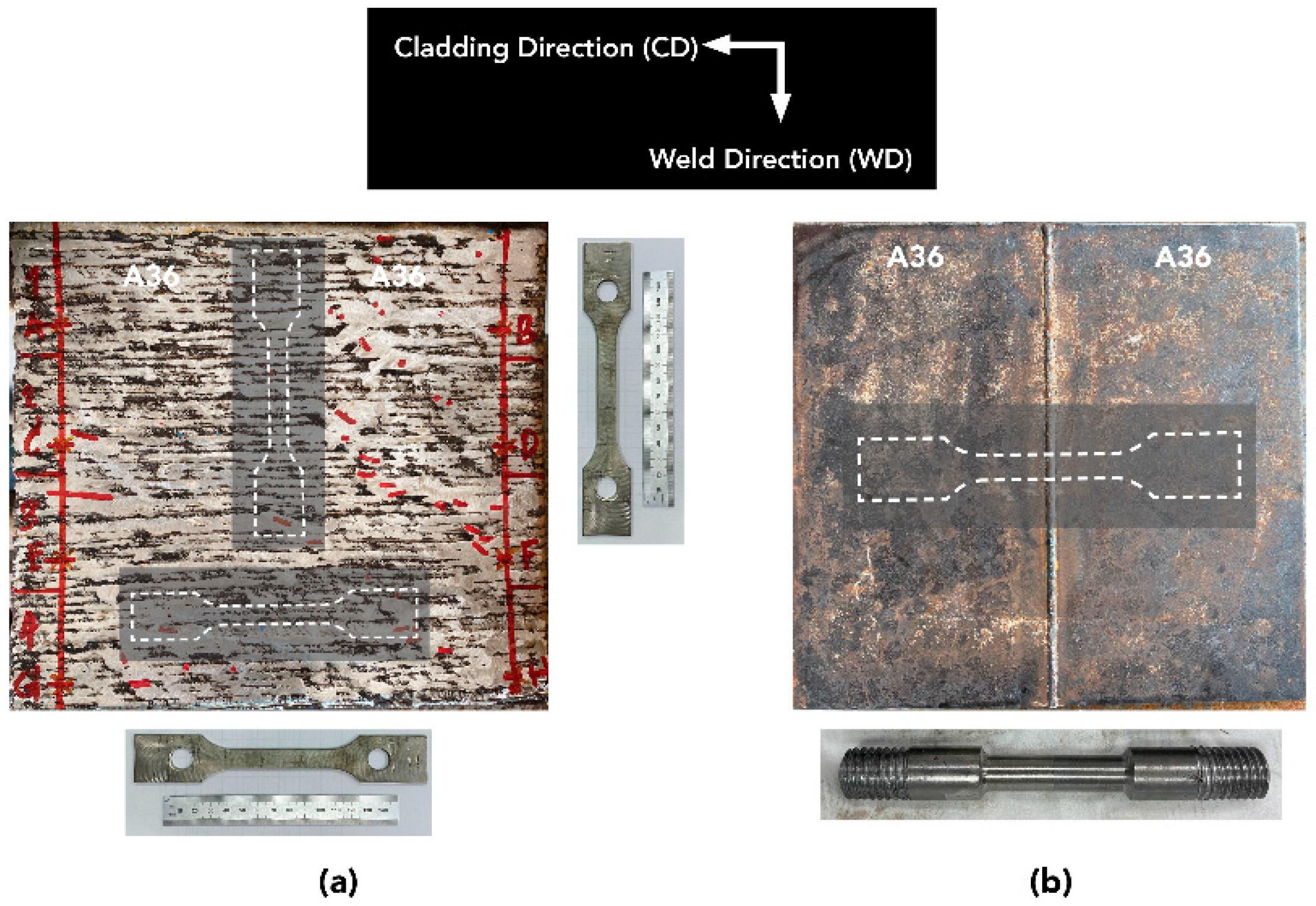
2.2. Cladding Process and Residual Stress Measurements

The welded plate was then coated by cladding its surface with 309L stainless steel (E309L-16), as demonstrated in Figure 3.
SMAW was carried out to create a hard-facing overlay of 2.8–3.0 mm. Note that the cladding direction was perpendicular to the weld direction or A36—A36 weldment. The detailed information about the SMAW process is described in Table 4. After the entire surface was coated with 309L stainless steel, the top surface (overlay) was ground to have approximately 2.8 mm thickness.
The residual stress measurements were carried out on the welded plates both before and after cladding to evaluate the internal stresses that resulted from the welding processes. A non-contact surface scanner (μ-X360s Portable X-ray Residual Stress Analyzer by PULSTEC, Hamamatsu, Japan) was used to measure the residual stress. Figure 4 displays the measurement locations (B1 to B9, and A1 to A4). Before the cladding, the residual stresses in all three zones (base, HAZ, and weld metal) were measured (Figure 4a). However, the residual stresses were checked in only the HAZ and weld metal zones of the cladding surface because these zones were vulnerable to heat.

2.3. Tensile Tests

Since the coated plate’s service life depended on its mechanical strength, each layer of cladding workpiece was extracted and tested by the tensile test, as described in Table 5, to determine its strength at elevated temperatures. Figure 5 shows the locations of the tensile testing specimens that were machined out of the cladding surface and substrate. The specimens in the cladding layer were cut into flat samples having a 50 mm gauge length and 12.5 mm width. The substrate specimens were machined into rod specimens with a 50 mm gauge length and 8.0 mm diameter. The Instron 1000 HDX machine ((Instron, Norwood, MA, USA) was used to carry out the tensile tests, and the pulling speed was 5 mm/min. Note that the tensile testing procedure followed the ASTM E8 standard [55].

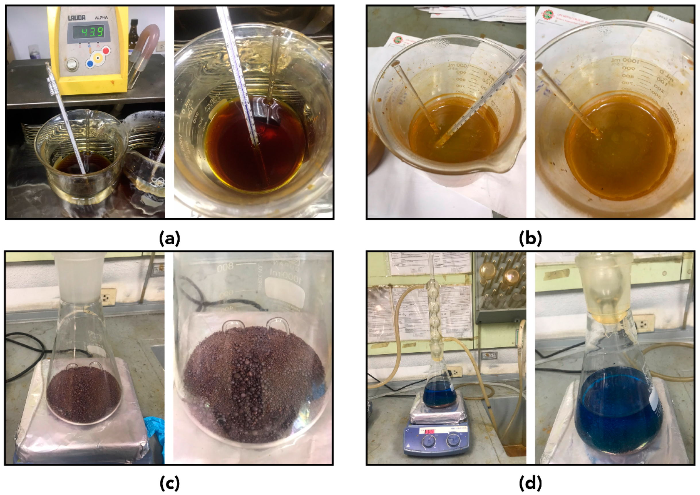
2.4. Corrosion Tests

Since the actual operating conditions were significantly affected by corrosion, three major corrosion tests were considered, as described in Table 6. The sites investigated for the corrosion tests are displayed in Figure 6.
In the pitting corrosion tests, the specimens were cut to 25 mm along the weld and 50 mm across the weld. Prior to the test, all surfaces of the samples were ground wet by 120-grit polishing. Pickling was performed for 5 min at 60 °C in a solution of 20% HNO3 and 5% HF. The specimens were cleaned by rinsing with water, then dipping in acetone, and being air-dried. Afterward, the samples were immersed in the 6% FeCl3·6H2O solution at a constant temperature of 50 °C for 24 h. Then specimens were cleaned, and the pitting evaluation was carried out by using the microscope. Figure 7a,b demonstrates the pitting corrosion test setup.
Figure 7c,d show the intergranular corrosion tests. Each specimen was machined to be 25 mm (width) by 100 mm (length) to achieve a smooth surface. Prior to or the test, the samples were cleaned with alcohol in the ultrasonic cleaner. In each intergranular corrosion test, a specimen was filled with a layer of copper shot on the bottom of the test flask and immersed in the dissolved 100 g of CuSO4·5H2O in 700 mL of distilled water. Then, 100 mL of sulfuric acid was added and filled with distilled water to acquire 1000 mL test solutions. The specimen in the test solution was then boiled for 24 h. Afterward, the specimen was cleaned in the ultrasonic cleaner and was air-dried. The face bend weld test was also carried out by bending the tested sample 180° over a mandrel with a radius not exceeding the specimen’s thickness.
The third corrosion test was to measure the weight loss of the base material (A36 steel) and the cladding layer (309L stainless steel—A36 steel). Each specimen was cut to a 25 mm (width) and 25 mm (length) size. The surface was ground wet by 120-grit and cleaned with alcohol in the ultrasonic cleaner. The specimen was then immersed in the 30% Nital test solution at constant room temperature for 24 h. Then, the sample was cleaned, and the weight loss measurement was performed.

2.5. Wear Tests

In the coal-fired power plants, structural systems were typically under worn out by erosion. As a result, a shot blasting experiment was carried out to observe the wear performance of the cladding surfaces, as seen in Figure 8. Two types of specimens were considered here: a substrate (A36—A36 welded plate), and a cladding (309L stainless steel). Each sample was cut to have dimensions of 50 mm in width, 75 mm in length, and 6 mm in thickness. In the shot blasting process, the specimen was placed into the chamber (Figure 7b), and the sands (250–425 μm in diameter) were blasted with 0.6 MPa using a nozzle having 6.25 mm in diameter. Three levels of shot blasting times were carried out (Table 7) and the accumulated weight loss after each time was measured.

3. Results

The results section is divided into three parts, as follows.

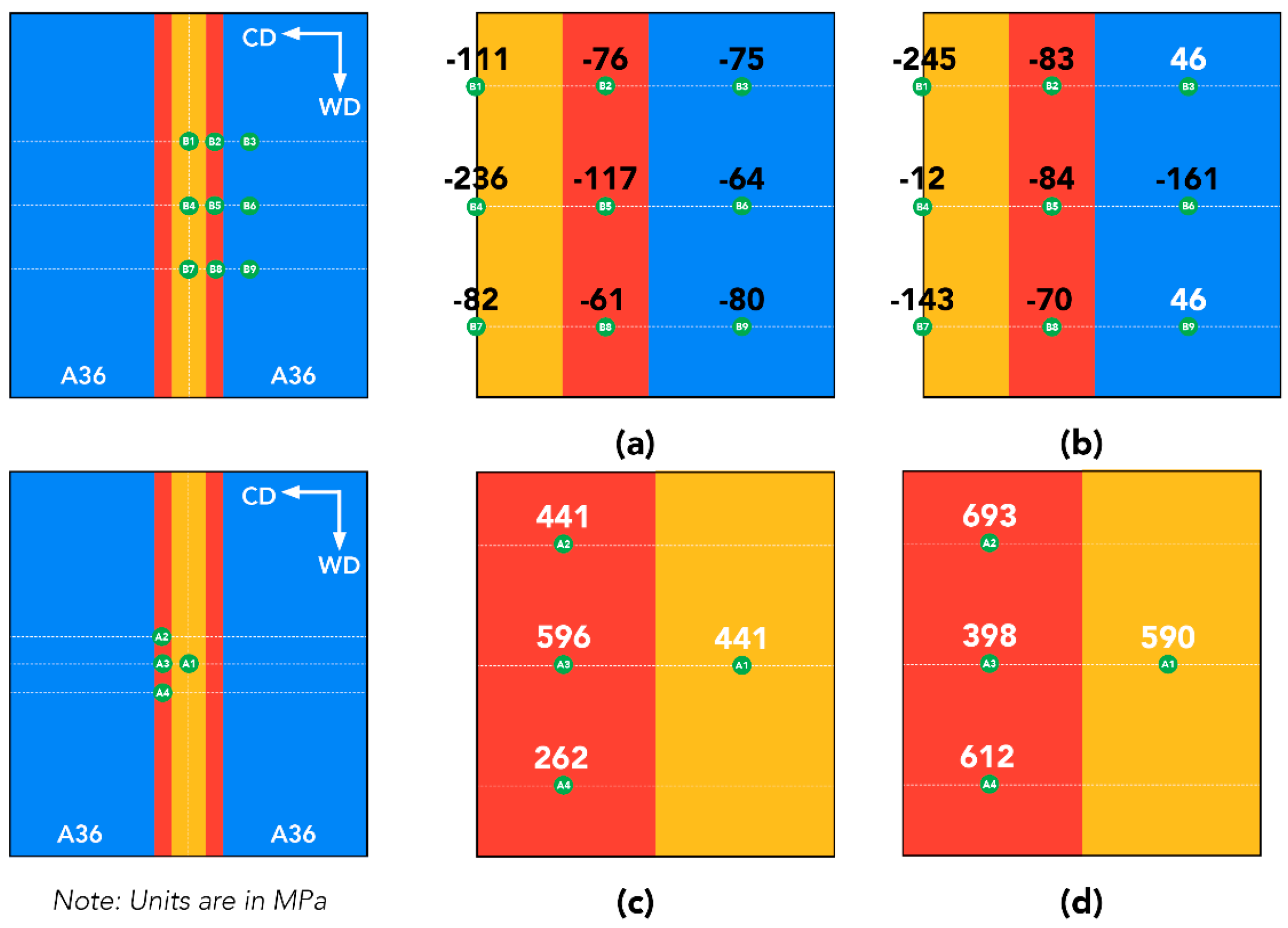
3.1. Residual Stress Measurement Results

The X-ray diffraction method used here provided the in-plane principal stresses in the weld direction (WD) and the cladding direction (CD), as illustrated in Figure 9. After the A36—A36 plates were welded together, the material within the welded plate started to shrink as it cooled down, and the residual stresses developed. The negative values were compressive stresses, and the positive values were tensile stresses. The high-stress concentration sites should be paid attention to because they could lead to reduced fatigue resistance. Before cladding (Figure 9a,b), the high compressive stress locations were mainly found in the weld metal and HAZ zones in the center area. Figure 9c,d shows the residual stress distributions in the concerned areas (weld metal and HAZ) after cladding. Since the X-ray diffraction measurement depth was shallow, the residual stresses after cladding were mainly caused by the hard facing overlay (309L stainless steel). The overall stress distribution was considered typical and would not lead to lower fatigue resistance.

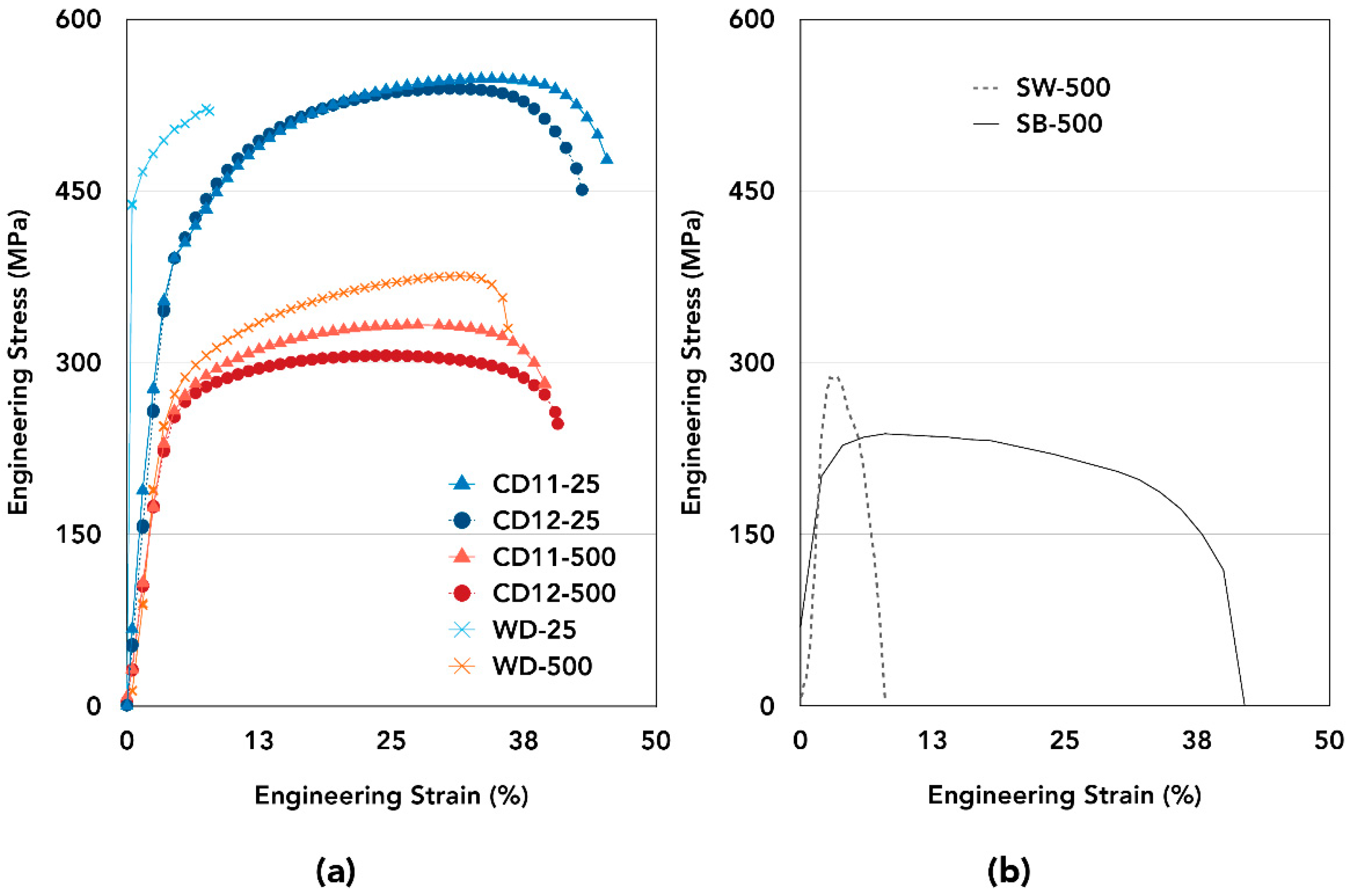
3.2. Tensile Testing Results

The stress-strain plots of the tensile tests are presented in Figure 10. The strengths of the cladding layers (flat specimens) are shown in Figure 10a, and those of the substrate layers (rod specimens) are displayed in Figure 10b.
At room temperature, the cladding layer (CD11-25) having 309L stainless steel (2.5 mm) and A36 steel (2.5 mm) offered the highest tensile strength (548 MPa) and elongation (37%). The addition of A36 steel thickness to 5.0 mm in CD12-25 provided slightly less tensile strength (540 MPa) and the same elongation. Only the 309L stainless steel layer in WD-25 provided lower tensile strength (522 MPa) and much lower elongation (6%). However, the cladding layer having only 309L stainless steel (WD-500) provided the highest tensile strength (376 MPa) and lowest elongation (26%) in comparison to the other cases at 500 °C. The cladding layer (CD11-500) having the same ratio of 309L stainless steel and A36 steel had a higher tensile strength (333 MPa) and slightly lower elongation (34%) than that of the case (CD12-500) having the ratio of 309L stainless to A36 steel of 1:2, which had a 306 MPa tensile strength and 37% elongation.
In Figure 10b, the tensile strength of the base material (SB-500) was 238 MPa with a 40% elongation. The tensile strength of the A36 welded plate (SW-500) provided a tensile strength of 288 MPa. Note that this condition’s elongation was very low since the sample was notched at the weld area to force breaking at low strain. The increased strength of the A36—A36 welded plate was still lower than the strengths of those with cladding layers in Figure 10a. Also, it could be observed that the addition of 2.5 mm 309L stainless steel to A36 substrate (CD11-550) could increase the tensile strength up to 16% at 500 °C in comparison with the A36—A36 welded plate (SW-500).

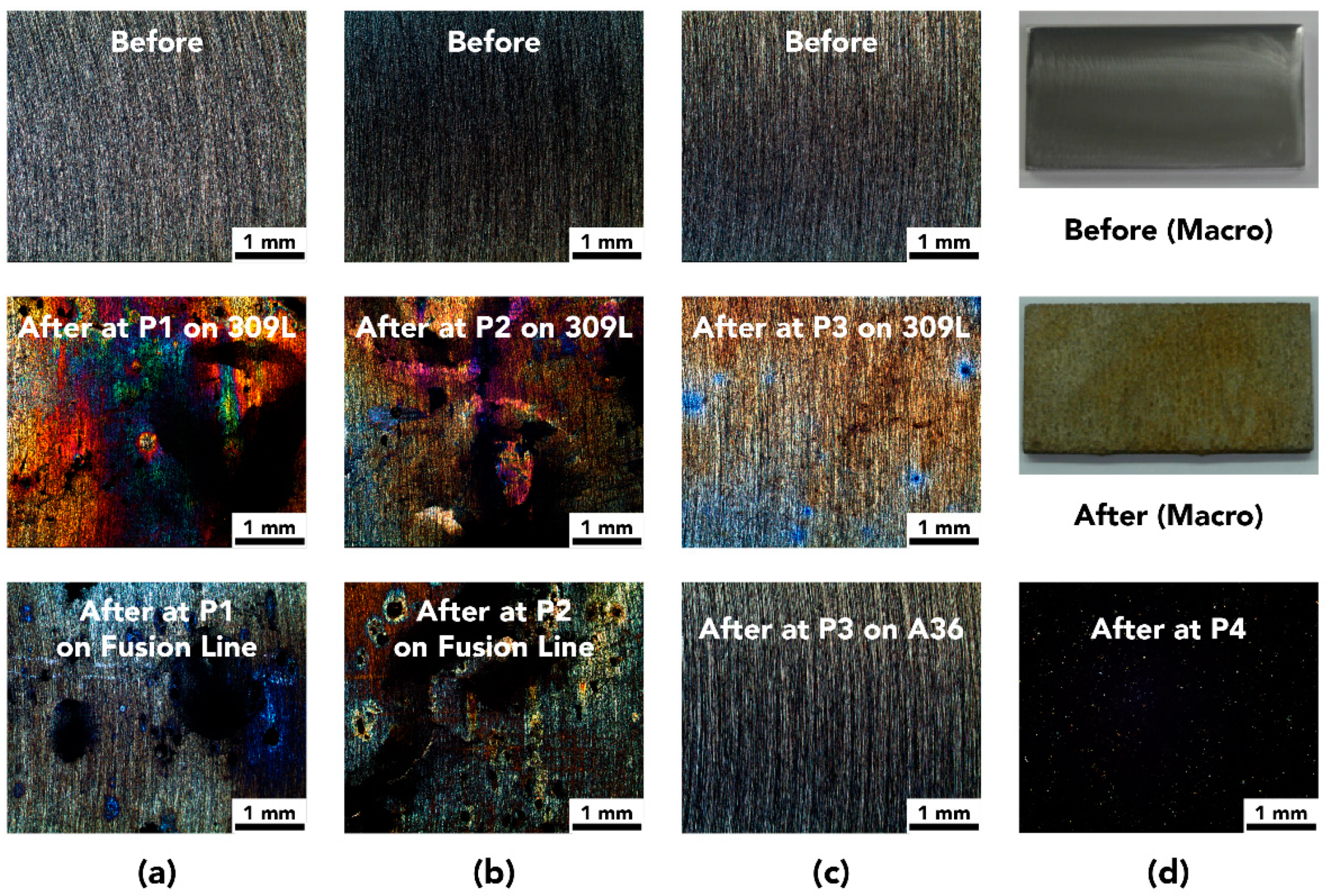
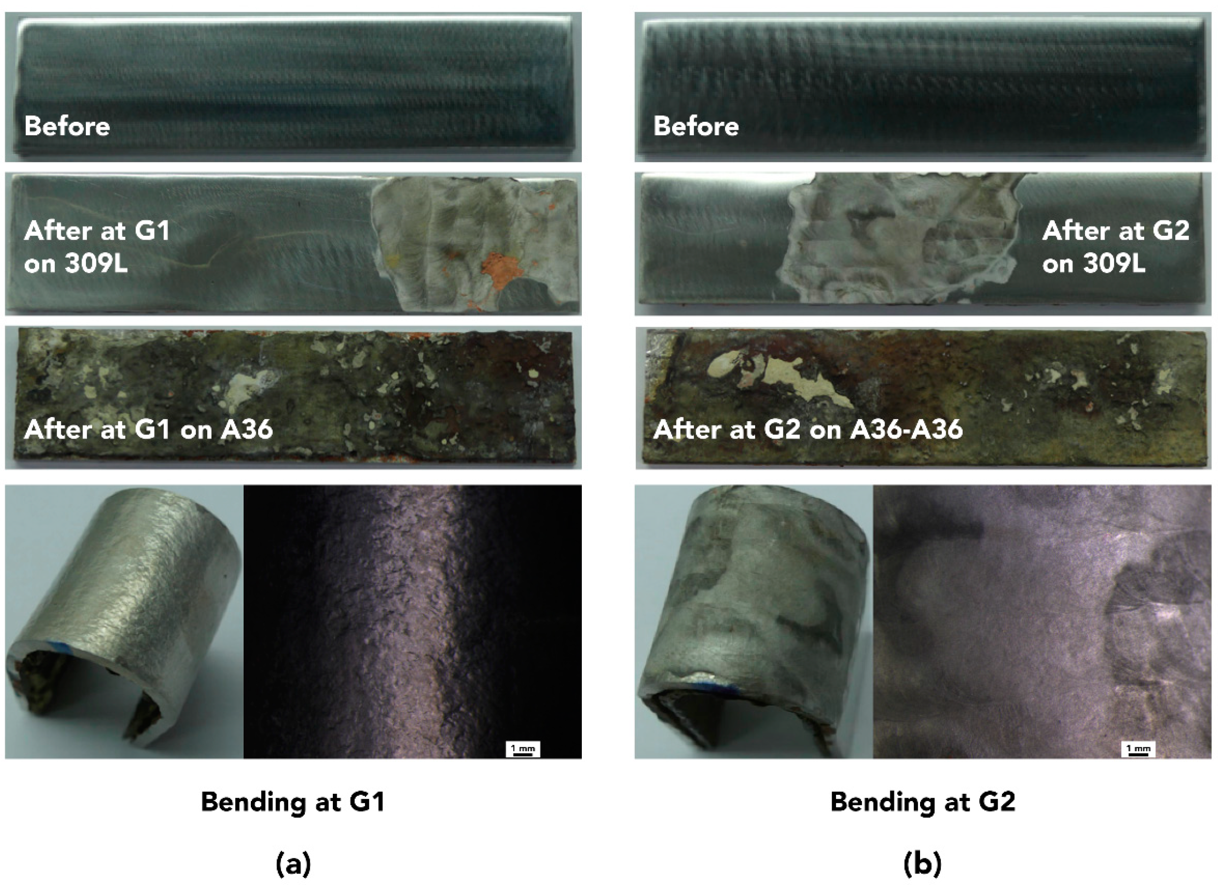
3.3. Corrosion Testing Results

The investigated areas (P1 to P4) of the pitting corrosions were observed in Figure 11 to detect if there existed any localized cavities or holes, which could lead to severe corrosion damage. On the cladding sites (P1 and P2), pitting corrosion occurred both on the 309L stainless steel layer. The sampled pitting corrosion sites could be seen in Figure 12, and the dimensions of a pitting site were displayed in Figure 13. These images were taken by using the high-resolution digital microscope (VHX-7000, Keyence, Itasca, IL, USA, 20 to 6000× magnification). Note that rust occurred on the surfaces shown in Figure 12 and Figure 13 because these samples were rested in the air for an extended period prior to the surface inspection.
At P3 (Figure 11), the localized cavities only appeared on the cladding layer (309L) but could not be observed on the base material side (A36). No pitting corrosions could be observed at P4 even after using the high-resolution digital microscope. As a result, 309L cladding provided pitting corrosion resistance to both the A36 base and A36—A36 weld material because localized corrosion attacks could not penetrate through the cladding layer. These results were consistent with Wang et al.’s that 309L did not corrode in the pitting corrosion tests [58].
When reheating a welded component, particularly in stainless steel welding, chromium (Cr)-rich grain boundary precipitates could lead to a local depletion of Cr adjacent to the precipitates, which could lead to a corrosive attack. In the heat-affected zone (HAZ), titanium or niobium could react with carbon to form carbides, causing intergranular corrosion or the so-called “knife-line” attack because these carbides build-up could not diffuse due to rapid cooling of the weld metal. Figure 14 shows the intergranular corrosion tests’ results in the HAZ areas (G1 and G2). Although the A36 base materials seemed to be significantly corroded, no intergranular (carbides build-up) were detected in both locations. As a result, the 309L stainless steel cladding could also be used as a protective layer for intergranular corrosion resistance.
Figure 15 shows the weight-loss corrosion test results observed at the base material (A36) and the cladding material (309L and A36). The observed corrosions seemed to be uniform for both sites (W1 and W2). The calculated weight losses for the A36 plate was 14.51, and 11.11 mg/mm2 for the cladding layer. The cladding layer could reduce the corrosion weight loss on the A36 plate by approximately 24%.
Overall, the 309L stainless steel cladding was effective in the corrosion resistance of the A36—A36 welded plate because no pitting and intergranular were noticed in the A36 areas. Moreover, the addition of the cladding layer could help slow down weight loss corrosion.

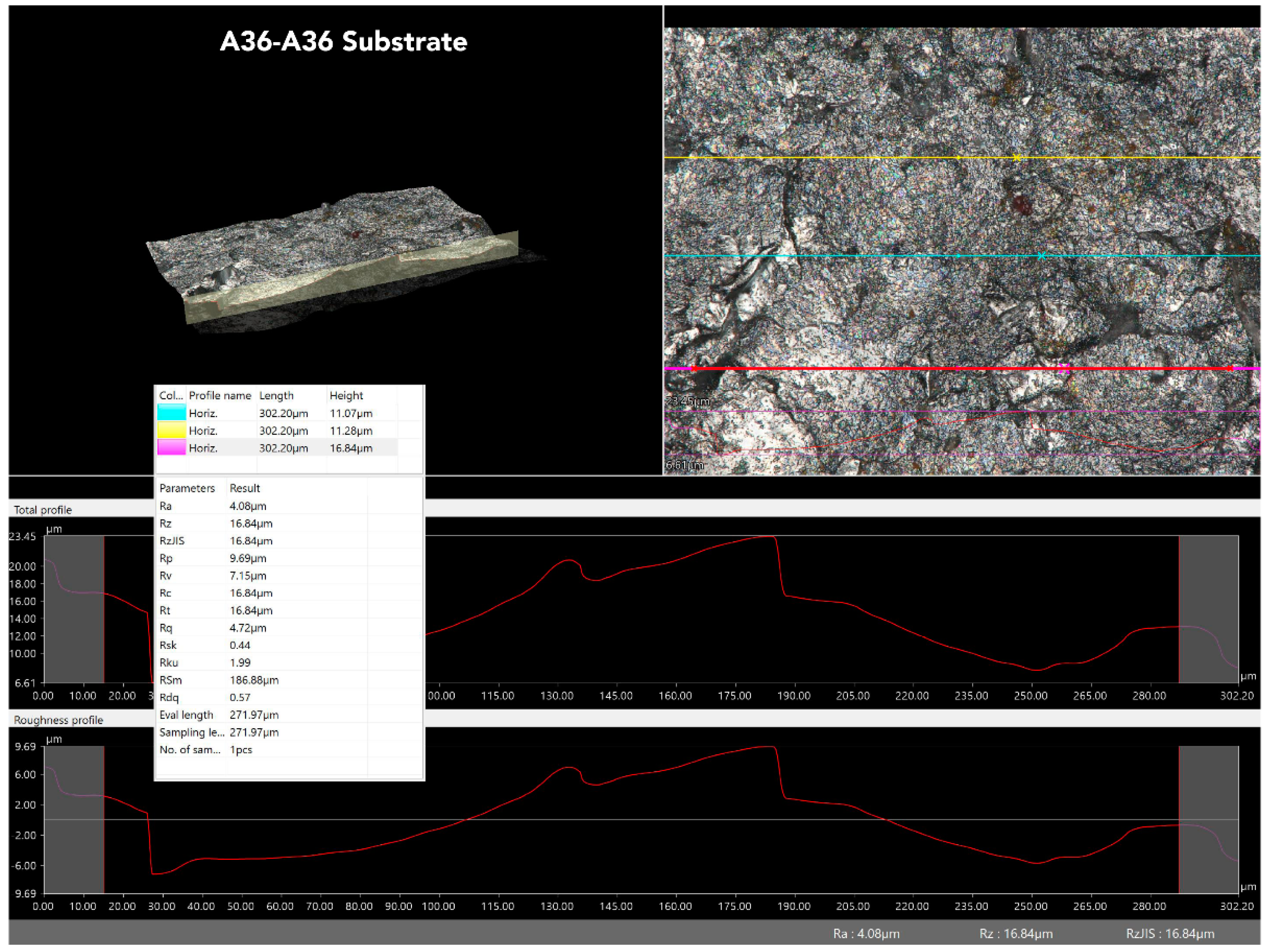
3.4. Wear Testing Results

The wear performance of the cladding surface could be observed in Figure 16. This figure compares the weight loss at varying shot blasting time between the substrate and the cladding. Increasing shot blasting time led to the increased weight loss of both surfaces since the top surface layers were eroded over time.
It could be noticed that the weight loss of the cladding surface was lower than that of the substrate over time. Since the density of A36 steel was 7.85 g/mm3 and the density of 309L stainless steel was 7.97 g/mm3, the calculated volume losses of the substrate and cladding were 0.248 and 0.226 mm3/h, respectively. The 309L stainless steel cladding surface reduced the volume loss by approximately 9%, which could provide improved surface protection and a longer lifetime to the A36—A36 welded steel, particularly in the erosion environment.
Figure 17 shows the top and cross-section views of the shot blasted surfaces. The surface roughness values of these surfaces were measured in Figure 18 and Figure 19. The less abrasive surface could be found on the 309L stainless steel cladding (Ra = 1.92 μm) than on the A36—A36 substrate (Ra = 4.08 μm), which corresponded to the 9% less volume loss.

4. Discussion

Based on the results, the cladding of 309L stainless steel on the A36—A36 welded steel plate offered higher tensile strength at elevated temperature, corrosion resistance, and wear performance compared to the cases with no cladding (A36—A36 only). Since the primary purpose of the cladding was only to extend the lifetime of the welded components temporarily, the evaluations carried out in this work indicated that the coating method was proven effective. The cladding layer of 309L stainless steel provided an approximately 16% increase in the tensile strength at 500 °C and offered a suitable protection layer to prevent any pitting and intergranular corrosions. The results obtained from this study agree with other existing studies suggesting that stainless steel weld cladding could be coated on a steel surface to prevent corrosion [55]. The findings from this study also confirmed that the 309L stainless cladding could be temporarily coated onto the A36—A36 welded components, particularly for the elevated temperature under such corrosive environments. This work’s implication was the significant cost-saving by simply cladding the welded pipes with 309L stainless steel.
The next step following this work would be looking at the appropriate ratios between the welded steel and cladding material. Thus, the chemical analysis would be necessary. Besides, the shear tests would be examined to evaluate the shear strengths of these coated materials. The creep performances of the coated materials must also be performed to determine if the cladding surfaces could be operated under the thermal-fatigue conditions. Our research group also planned to develop a buffer layer to increase the oval performance and extend the coated materials’ lifetime. The immediate implication of these studies was to apply the same coating technique in dissimilar welds, which were also commonly used in power plants.

5. Conclusions

This study evaluated the mechanical properties of the 309L stainless steel cladding on the A36—A36 welded plate. The welded samples were prepared by the GTAW and SMAW processes, and the cladding layer was coated onto the welded plate by SMAW. The residual stress measurements were carried out to observe the stress distributions after welding. The tensile strengths of the cladding samples at various layers were also investigated by using the tensile tests. Different sites of the cladding samples were also observed under the pitting, intergranular, and weight loss corrosive conditions. Finally, the shot blasting tests were conducted to determine the wear resistance performance of the coated surfaces. The key findings of this study were as follows:
  • The high compressive stress locations were mainly found in the Weld Metal and HAZ zones in the center area of the cladding surface. However, the overall stress distribution was considered typical and would not lead to lower fatigue resistance.
  • The increased tensile strength of 16% at 500 °C could be obtained by cladding 309L stainless steel on the A36—A36 welded plate.
  • No pitting and intergranular corrosions could be observed on A36 base material if coated with 309L stainless steel cladding. Also, the cladding layer improved weight loss corrosion by 24%.
  • The 309L stainless steel cladding provided less volume loss of 9% compared to that of the A36—A36 welded plate with no coating under the shot blasting wear tests.
The obtained results indicated that the 309L stainless steel cladding could be used to temporarily extend the lifetime of A36—A36 welded components in elevated temperature under corrosive and erosive conditions.

Author Contributions

Conceptualization, N.M., M.N., P.T., and S.S.; Data curation, P.P., N.M., and P.T.; Formal analysis, P.P., K.S.-n., P.T., and S.S.; Funding acquisition, N.M.; Investigation, N.M., K.S.-n., and M.N.; Methodology, P.P., N.M., M.N., P.T., and S.S.; Project administration, N.M.; Resources, N.M., M.N., and P.T.; Software, N.M. and S.S.; Supervision, N.M., P.T., and K.D.; Validation, K.S.-n., M.N., P.T., and S.S.; Visualization, P.P., N.M., and K.S.-n.; Writing—original draft, P.P.; Writing—review and editing, N.M. All authors have read and agreed to the published version of the manuscript.

Funding

This research was funded by the Thailand Research Fund (TRF), grant number PHD5910086. The APC was funded by Khon Kaen University.

Acknowledgments

The authors would like to acknowledge the supports of LPN Metallurgical Research Center; Department of Mechanical Engineering, Faculty of Engineering, Khon Kaen University; King Mongkut’s University of Technology Thonburi; National Metal and Materials Technology Center (MTEC); and Department of Mechanical Engineering, Northwestern University.

Conflicts of Interest

The authors declare no conflict of interest.

References

  1. ASTM International. ASTM A36/A36M-19, Standard Specification for Carbon Structural Steel; ASTM International: West Conshohocken, PA, USA, 2019. [Google Scholar]
  2. Chen, H.; Pan, P.; Wang, Y.; Zhao, Q. Field study on the corrosion and ash deposition of low-temperature heating surface in a large-scale coal-fired power plant. Fuel 2017, 208, 149–159. [Google Scholar] [CrossRef]
  3. Chen, H.; Pan, P.; Shao, H.; Wang, Y.; Zhao, Q. Corrosion and viscous ash deposition of a rotary air preheater in a coal-fired power plant. Appl. Therm. Eng. 2017, 113, 373–385. [Google Scholar] [CrossRef]
  4. McEvily, A.J. Atlas of Stress-Corrosion and Corrosion Fatigue Curves; ASM International: West Conshohocken, PA, USA, 1990. [Google Scholar]
  5. Hussain, T.; Syed, A.U.; Simms, N.J. Trends in fireside corrosion damage to superheaters in air and oxy-firing of coal/biomass. Fuel 2013, 113, 787–797. [Google Scholar] [CrossRef] [Green Version]
  6. Kumar, S.; Kumar, M.; Handa, A. Combating hot corrosion of boiler tubes—A study. Eng. Fail. Anal. 2018, 94, 379–395. [Google Scholar] [CrossRef]
  7. Rahman Rashid, R.A.; Abaspour, S.; Palanisamy, S.; Matthews, N.; Dargusch, M.S. Metallurgical and geometrical characterisation of the 316L stainless steel clad deposited on a mild steel substrate. Surf. Coat. Technol. 2017, 327, 174–184. [Google Scholar] [CrossRef]
  8. Chen, C.X.; Liu, M.Y.; Liu, B.X.; Yin, F.X.; Dong, Y.C.; Zhang, X.; Zhang, F.Y.; Zhang, Y.G. Tensile shear sample design and interfacial shear strength of stainless steel clad plate. Fusion Eng. Des. 2017, 125, 431–441. [Google Scholar] [CrossRef]
  9. Liu, B.X.; Wang, S.; Fang, W.; Ma, J.L.; Yin, F.X.; He, J.N.; Feng, J.H.; Chen, C.X. Microstructure and mechanical properties of hot rolled stainless steel clad plate by heat treatment. Mater. Chem. Phys. 2018, 216, 460–467. [Google Scholar] [CrossRef]
  10. Kono, D.; Maruhashi, A.; Yamaji, I.; Oda, Y.; Mori, M. Effects of cladding path on workpiece geometry and impact toughness in Directed Energy Deposition of 316L stainless steel. CIRP Ann. 2018, 67, 233–236. [Google Scholar] [CrossRef]
  11. Farias, F.W.C.; Filho, J.C.P.; de Azevedo, L.M.B. Microstructural and mechanical characterization of the transition zone of 9% Ni steel cladded with Ni-based superalloy 625 by GTAW-HW. Metals 2018, 8, 1007. [Google Scholar] [CrossRef] [Green Version]
  12. Xue, J.; Bouchard, J.; Chen, X.; Fan, Z.; Zhou, Y. Anisotropic elastic constants calculation of stainless steel cladded layers of pressure vessel steel plate. Int. J. Press. Vessel. Pip. 2019, 177, 103991. [Google Scholar] [CrossRef]
  13. Li, C.A.; Qin, G.; Tang, Y.; Zhang, B.; Lin, S.; Geng, P. Microstructures and mechanical properties of stainless steel clad plate joint with diverse filler metals. J. Mater. Res. Technol. 2020, 9, 2522–2534. [Google Scholar] [CrossRef]
  14. Ban, H.; Zhu, J.; Shi, G. Cyclic loading tests on welded connections of stainless-clad bimetallic steel and modelling. J. Constr. Steel Res. 2020, 171, 106140. [Google Scholar] [CrossRef]
  15. Ban, H.; Bai, R.; Chung, K.-F.; Bai, Y. Post-fire material properties of stainless-clad bimetallic steel. Fire Saf. J. 2020, 112, 102964. [Google Scholar] [CrossRef]
  16. Kim, Y.; Nam, H.; Lee, J.; Park, C.; Moon, B.; Nam, D.-G.; Lee, S.H.; Kang, N. Hot-cracking resistivity of dissimilar clads using Inconel 52 and 308L stainless steel on carbon steel. J. Nucl. Mater. 2020, 533, 152103. [Google Scholar] [CrossRef]
  17. Gomes, J.H.F.; Paiva, A.P.; Costa, S.C.; Balestrassi, P.P.; Paiva, E.J. Weighted multivariate mean square error for processes optimization: A case study on flux-cored arc welding for stainless steel claddings. Eur. J. Oper. Res. 2013, 226, 522–535. [Google Scholar] [CrossRef]
  18. Kumar, G.S.; Saravanan, S.; Balan, A.V.; Oscar, J.; Ragunath, R.; Ramesh, M. Influence of FCAW process parameters in super duplex stainless steel claddings. Mater. Today Proc. 2020, 21, 63–65. [Google Scholar] [CrossRef]
  19. Eghlimi, A.; Shamanian, M.; Raeissi, K. Effect of current type on microstructure and corrosion resistance of super duplex stainless steel claddings produced by the gas tungsten arc welding process. Surf. Coat. Technol. 2014, 244, 45–51. [Google Scholar] [CrossRef]
  20. Shihab, S.K.; Mohamed, R.H.; Mubarek, E.M. Optimization of process parameters in cladding of stainless steel over mild steel. Mater. Today Proc. 2019, 16, 816–823. [Google Scholar] [CrossRef]
  21. Singhal, T.S.; Jain, J.K. GMAW cladding on metals to impart anti-corrosiveness: Machine, processes and materials. Mater. Today Proc. 2020, 26, 2432–2441. [Google Scholar] [CrossRef]
  22. Padhiar, S.A.; Vincent, S. Effect of hard facing processes on mild steel A-36 by arc welding. Mater. Today Proc. 2020, 28, 526–531. [Google Scholar] [CrossRef]
  23. Kang, K.; Kawahito, Y.; Gao, M.; Zeng, X. Effects of laser-arc distance on corrosion behavior of single-pass hybrid welded stainless clad steel plate. Mater. Des. 2017, 123, 80–88. [Google Scholar] [CrossRef]
  24. Erfanmanesh, M.; Shoja-Razavi, R.; Abdollah-Pour, H.; Mohammadian-Semnani, H. Influence of using electroless Ni–P coated WC–Co powder on laser cladding of stainless steel. Surf. Coat. Technol. 2018, 348, 41–54. [Google Scholar] [CrossRef]
  25. Murkute, P.; Pasebani, S.; Isgor, O.B. Production of corrosion-resistant 316L stainless steel clads on carbon steel using powder bed fusion-selective laser melting. J. Mater. Process. Technol. 2019, 273, 116243. [Google Scholar] [CrossRef]
  26. Segura, I.A.; Murr, L.E.; Terrazas, C.A.; Bermudez, D.; Mireles, J.; Injeti, V.S.V.; Li, K.; Yu, B.; Misra, R.D.K.; Wicker, R.B. Grain boundary and microstructure engineering of Inconel 690 cladding on stainless-steel 316L using electron-beam powder bed fusion additive manufacturing. J. Mater. Sci. Technol. 2019, 35, 351–367. [Google Scholar] [CrossRef]
  27. Li, G.; Gan, Y.; Liu, C.; Shi, Y.; Zhao, Y.; Kou, S. Corrosion and wear resistance of Fe-based amorphous coatings. Coatings 2020, 10, 73. [Google Scholar] [CrossRef] [Green Version]
  28. Yu, J.; Sun, W.; Huang, H.; Huang, Y. Study on the deformation control and microstructures of thin-walled parts repaired by laser cladding. Coatings 2020, 10, 369. [Google Scholar] [CrossRef] [Green Version]
  29. Li, B.; Zhu, H.; Qiu, C.; Gong, X. Laser cladding and in-situ nitriding of martensitic stainless steel coating with striking performance. Mater. Lett. 2020, 259, 126829. [Google Scholar] [CrossRef]
  30. Mahmoud, E.R.I.; Khan, S.Z.; Ejaz, M. Laser surface cladding of mild steel with 316L stainless steel for anti-corrosion applications. Mater. Today Proc. 2020. [Google Scholar] [CrossRef]
  31. Liu, B.X.; Wang, S.; Fang, W.; Yin, F.X.; Chen, C.X. Meso and microscale clad interface characteristics of hot-rolled stainless steel clad plate. Mater. Charact. 2019, 148, 17–25. [Google Scholar] [CrossRef]
  32. Xu, Y.; Li, Z.; Liu, J.; Chen, Y.; Zhang, F.; Wu, L.; Hao, J.; Liu, L. Microstructure evolution and properties of laser cladding CoCrFeNiTiAlx high-entropy alloy coatings. Coatings 2020, 10, 373. [Google Scholar] [CrossRef] [Green Version]
  33. Li, B.C.; Zhu, H.M.; Qiu, C.J.; Zhang, D.K. Development of high strength and ductile martensitic stainless steel coatings with Nb addition fabricated by laser cladding. J. Alloys Compd. 2020, 832, 154985. [Google Scholar] [CrossRef]
  34. Moskal, G.; Niemiec, D.; Chmiela, B.; Kałamarz, P.; Durejko, T.; Ziętala, M.; Czujko, T. Microstructural characterization of laser-cladded NiCrAlY coatings on Inconel 625 Ni-based superalloy and 316L stainless steel. Surf. Coat. Technol. 2020, 387, 125317. [Google Scholar] [CrossRef]
  35. Shen, F.; Tao, W.; Li, L.; Zhou, Y.; Wang, W.; Wang, S. Effect of microstructure on the corrosion resistance of coatings by extreme high speed laser cladding. Appl. Surf. Sci. 2020, 517, 146085. [Google Scholar] [CrossRef]
  36. Venkatesh, B.; Sriker, K.; Prabhakar, V.S.V. Wear characteristics of hard facing alloys: State-of-the-art. Procedia Mater. Sci. 2015, 10, 527–532. [Google Scholar] [CrossRef] [Green Version]
  37. Shi, Q.; Zhu, H.; Li, C. The effects of the addition of Ti3SiC2 on the microstructure and properties of laser cladding composite coatings. Coatings 2020, 10, 498. [Google Scholar] [CrossRef]
  38. Wang, H.; Zhang, W.; Peng, Y.; Zhang, M.; Liu, S.; Liu, Y. Microstructures and wear resistance of FeCoCrNi-Mo high entropy alloy/diamond composite coatings by high speed laser cladding. Coatings 2020, 10, 300. [Google Scholar] [CrossRef] [Green Version]
  39. Zhang, M.; Li, M.; Wang, S.; Chi, J.; Ren, L.; Fang, M.; Zhou, C. Enhanced wear resistance and new insight into microstructure evolution of in-situ (Ti,Nb)C reinforced 316 L stainless steel matrix prepared via laser cladding. Opt. Lasers Eng. 2020, 128, 106043. [Google Scholar] [CrossRef]
  40. Singh, J.; Thakur, L.; Angra, S. An investigation on the parameter optimization and abrasive wear behaviour of nanostructured WC–10Co–4Cr TIG weld cladding. Surf. Coat. Technol. 2020, 386, 125474. [Google Scholar] [CrossRef]
  41. Singh, J.; Thakur, L.; Angra, S. Abrasive wear behavior of WC–10Co–4Cr cladding deposited by TIG welding process. Int. J. Refract. Met. Hard Mater. 2020, 88, 105198. [Google Scholar] [CrossRef]
  42. Singh, J.; Singh Chatha, S.; Singh Sidhu, B. Effect of surface alloying on wear behaviour of En-47 steel. Mater. Today Proc. 2020, 21, 1340–1349. [Google Scholar] [CrossRef]
  43. Sekhar, B.R.; Nayak, R.K.; Rout, S.R.; Masanta, M. Wear characteristic of TiC coated AISI 1020 mild steel fabricated by TIG cladding method. Mater. Today Proc. 2020, 26, 3288–3291. [Google Scholar] [CrossRef]
  44. Labiapari, W.S.; Ardila, M.A.N.; Costa, H.L.; de Mello, J.D.B. Micro abrasion-corrosion of ferritic stainless steels. Wear 2017, 376–377, 1298–1306. [Google Scholar] [CrossRef]
  45. Zhang, Z.; Kovacevic, R. Laser cladding of iron-based erosion resistant metal matrix composites. J. Manuf. Process. 2019, 38, 63–75. [Google Scholar] [CrossRef]
  46. Ni, X.; Wang, S.; Zhao, Y.; Li, W.; Jiao, X. Investigation on Microstructure, Hardness, and Corrosion Resistance of Mo–Ni–B Coatings Prepared by Laser Cladding Technique. Coatings 2019, 9, 856. [Google Scholar] [CrossRef] [Green Version]
  47. Li, H.; Zhang, L.; Zhang, B.; Zhang, Q. Effect of substrate on metallographic corrosion of cladding in stainless/carbon steel bimetal plate. Results Phys. 2020, 16, 102925. [Google Scholar] [CrossRef]
  48. Lima, C.R.C.; Belém, M.J.X.; Fals, H.D.C.; Rovere, C.A.D. Wear and corrosion performance of Stellite 6® coatings applied by HVOF spraying and GTAW hotwire cladding. J. Mater. Process. Technol. 2020, 284, 116734. [Google Scholar] [CrossRef]
  49. Li, Y.; Tan, N.; Jin, G.; Cui, X.; Li, Q. Thermal fatigue failure behavior of surface/interface of plasma cladding layer. Coatings 2019, 9, 646. [Google Scholar] [CrossRef] [Green Version]
  50. Latha, S.; Nandagopal, M.; Parameswaran, P.; Reddy, G.V.P. Effect of P and Si on creep induced precipitation in 20% CW Ti-modified 14Cr-15Ni stainless steel fast reactor clad. Mater. Sci. Eng. A 2019, 759, 736–744. [Google Scholar] [CrossRef]
  51. Meng, Y.; Kang, K.; Gao, M.; Zeng, X. Microstructures and properties of single-pass laser-arc hybrid welded stainless clad steel plate. J. Manuf. Process. 2018, 36, 293–300. [Google Scholar] [CrossRef]
  52. Mohammed, R.; Kumar, E.N.; Ram, G.D.J.; Kamaraj, M.; Reddy, G.M.; Rao, K.S. Microstructure, mechanical and corrosion behaviour of weld overlay cladding of DMR 249A steel with AISI 308L. Mater. Today Proc. 2019, 15, 2–10. [Google Scholar] [CrossRef]
  53. Varghese, P.; Vetrivendan, E.; Dash, M.K.; Ningshen, S.; Kamaraj, M.; Kamachi Mudali, U. Weld overlay coating of Inconel 617 M on type 316 L stainless steel by cold metal transfer process. Surf. Coat. Technol. 2019, 357, 1004–1013. [Google Scholar] [CrossRef]
  54. Luz, F.S.D.; Pinheiro, W.A.; Monteiro, S.N.; Candido, V.S.; Silva, A.C.R.D. Mechanical properties and microstructural characterization of a novel 316L austenitic stainless steel coating on A516 Grade 70 carbon steel weld. J. Mater. Res. Technol. 2020, 9, 636–640. [Google Scholar] [CrossRef]
  55. ASTM International. ASTM E8/E8M-16ae1, Standard Test Methods for Tension Testing of Metallic Materials; ASTM International: West Conshohocken, PA, USA, 2016. [Google Scholar]
  56. ASTM International. ASTM G48-03, Standard Test Methods for Pitting and Crevice Corrosion Resistance of Stainless Steels and Related Alloys by Use of Ferric Chloride Solution; ASTM International: West Conshohocken, PA, USA, 2003. [Google Scholar]
  57. ASTM International. ASTM A262-15, Standard Practices for Detecting Susceptibility to Intergranular Attack in Austenitic Stainless Steels; ASTM International: West Conshohocken, PA, USA, 2015. [Google Scholar]
  58. Wang, Z.; Xu, J.; Shoji, T.; Takeda, Y.; Yuya, H.; Ooyama, M. Microstructure and pitting behavior of the dissimilar metal weld of 309L cladding and low alloy steel A533B. J. Nucl. Mater. 2018, 508, 1–11. [Google Scholar] [CrossRef]
Figure 1. The substrate specimen preparation process: (a) Specimen dimensions; (b) A36—A36 specimens; (c) A36—A36 welded plate; (d) Welding processes; (e) Post-weld heat treatment.
Coatings 10 00844 g001
Figure 2. The illustration of the welded joint (base, HAZ, and weld metal zones).
Coatings 10 00844 g002
Figure 3. The schematic of the cladding process: (a) Shielded metal arc welding (SMAW); (b) A36—A36 welded substrate; (c) Hard facing overlay; (d) Grinding; (e) Cladding surface.
Coatings 10 00844 g003
Figure 4. The residual stress measurement: (a) Residual stress measurement before cladding; (b) Residual stress measurement after cladding.
Coatings 10 00844 g004
Figure 5. The tensile testing specimens: (a) Tensile (flat) specimens location on cladding surface; (b) Tensile (rod) specimen location on A36—A36 welded plate.
Coatings 10 00844 g005
Figure 6. The investigated sites for the corrosion tests.
Coatings 10 00844 g006
Figure 7. The corrosion tests: (a) Pitting corrosion tests under 6% FeCl3·6H2O at 50 °C for 0 h; (b) Pitting corrosion tests under 6% FeCl3·6H2O at 50 °C for 24 h; (c) Intergranular corrosion tests under CuSO4·5H2O and sulfuric acid at 0 h; (d) Intergranular corrosion tests under CuSO4·5H2O and sulfuric acid at 24 h.
Coatings 10 00844 g007
Figure 8. The shot blasting wear test: (a) Shot blasting machine; (b) Specimen placement in the shot blasting machine; (c) Weight loss measurement after shot blasting.
Coatings 10 00844 g008
Figure 9. The results of the measured residual stresses: (a) Before cladding in WD; (b) Before cladding in CD; (c) After cladding in WD; (d) After cladding in CD.
Coatings 10 00844 g009
Figure 10. The tensile testing results: (a) flat specimens; (b) rod specimens.
Coatings 10 00844 g010
Figure 11. The pitting corrosion testing results: (a) Cladding layer over weldment (P1); (b) Cladding layer (P2); (c) Cladding-substrate layer (P3); (d) Substrate layer (P4). Note that all the images were magnified at 20× except those stating “macro”.
Coatings 10 00844 g011
Figure 12. The pitting locations sampled from the P1 and P2 areas.
Coatings 10 00844 g012
Figure 13. The measured dimensions of the selected pitting location.
Coatings 10 00844 g013
Figure 14. The intergranular corrosion testing results: (a) Cladding layer over weldment (G1); (b) Cladding-substrate layer over weldment (G2).
Coatings 10 00844 g014
Figure 15. The weight loss corrosion testing results: (a) A36 plate (W1); (b) 309L cladding on A36 plate (W2).
Coatings 10 00844 g015
Figure 16. The results of the shot blasting wear tests.
Coatings 10 00844 g016
Figure 17. The images of the shot blasted surfaces: (a) 309L cladding; (b) A36—A36 substrate.
Coatings 10 00844 g017
Figure 18. The measured surface roughness values of A36—A36 substrate.
Coatings 10 00844 g018
Figure 19. The measured surface roughness values of 309L cladding.
Coatings 10 00844 g019
Table 1. Welding process conditions for weld specimens preparation.
Welding ProcessNumber of LayersFiller MetalCurrent Type and PolarityCurrent (Amp)Voltage (V)Travel Speed (mm/min)
GTAW1–2ER70S-6
(2.4 mm Diameter)
DCEN90–14010–1550–100
SMAW3–13E7016
(3.2 mm Diameter)
DECP, AC90–13022–3060–120
Table 2. Chemical compositions of the considered materials in this study.
Chemical Composition (wt.%)
MaterialCMnCrSiMoNiCuSP
ASTM A360.250 max.0.850–1.3500.400 max.0.0300.030
ER70S-60.1001.5600.0200.860<0.0100.0100.2400.0120.012
E70160.0800.9400.0200.600<0.1000.0100.0060.004
E309L-160.0400.500–2.50022.000–25.0001.0000.75012.000–14.0000.7500.0300.040
Table 3. Mechanical properties of the considered materials in this study.
Mechanical Properties
MaterialYield Strength (N/mm2)Tensile Strength (N/mm2)Elongation (%)
ASTM A36250400–55023
ER70S-642055035
E701642052033
E309L-1642052030
Table 4. Cladding process condition.
Welding ProcessNumber of LayersFiller MetalCurrent Type and PolarityCurrent (Amp)Voltage (V)Travel Speed (mm/min)
SMAW1E309L-16
(3.2 mm diameter)
DECP, AC80–8620–24144–174
Table 5. Considered conditions in the tensile tests.
Test NumbersLayersOrientationsMaterialsThickness (mm)Temperatures (°C)
CD11-25CladdingCladding Direction309L Stainless Steel2.525
A36 Steel2.5
CD12-25CladdingCladding Direction309L Stainless Steel2.525
A36 Steel5.0
CD11-500CladdingCladding Direction309L Stainless Steel2.5500
A36 Steel2.5
CD12-500CladdingCladding Direction309L Stainless Steel2.5500
A36 Steel5.0
WD-25CladdingWeld Direction309L Stainless Steel2.825
WD-500CladdingWeld Direction309L Stainless Steel2.8500
SB-500SubstrateRolling DirectionA36 Steel (Base Material)8.0 (diameter)500
SW-500SubstrateWelding DirectionA36—A36 Welded Steel8.0 (diameter) 1500
1 The rod specimen was notched at the weldment to ensure breaking at low strain.
Table 6. Considered conditions in the corrosion tests.
TestsStandardsLayersMaterials
Pitting CorrosionASTM G48 A [56]Cladding Layer over Weldment (P1)309L Stainless Steel
Cladding Layer (P2)309L Stainless Steel
Cladding-Substrate Layer (P3)309L Stainless Steel—A36 Steel
Substrate Layer (P4)A36 Steel
Intergranular CorrosionASTM 262 E [57]Cladding Layer over Weldment (G1)309L Stainless Steel
Cladding-Substrate Layer over Weldment (G2)309L Stainless Steel—A36 Steel
Weight Loss CorrosionNoneSubstrate Layer (W1)A36 Steel
Cladding Layer (W2)309L Stainless Steel—A36 Steel
Table 7. The considered conditions in the shot blasting tests.
ParametersConsidered Conditions
MaterialsSubstrate (A36—A36 welded plate), Cladding (309L stainless steel)
Shot blasting time (s)150, 270, 390

