1. Introduction
Supplying 16.4% of global electricity annually and 85% of global renewable electricity, hydropower has experienced an upsurge in development, with an International Energy Agency report stating emerging economies have the potential to double hydroelectric production by 2050. During the past decade, hydropower has reached 1000 GW of total capacity, with 40 GW installed in 2013 alone, according to a 2017 report by the World Energy Council. In this light, the development of novel designs for hydropower plants is of high interest.
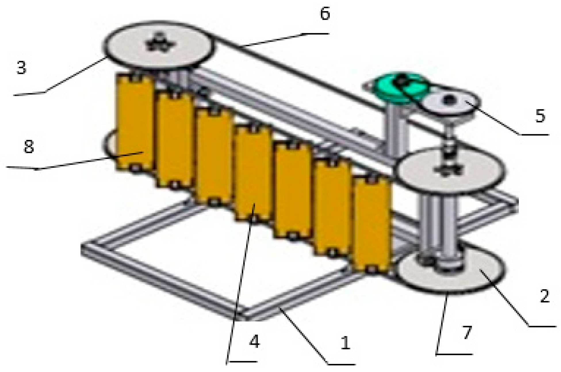
The developed mini-hydropower plant (mini-HPP), based on the Lenyov hydrobelt (
Figure 1), consists of a frame (1), two shafts (2, 3), blades (4), and two-stage gearboxes (5) installed on it. The mechanism for transmitting rotational energy is made in the form of a chain (6, 7) [
1]. Rectangular blades are periodically located in the plane of identical profiles and are a double-row lattice of a closed belt (8). The flow of the medium is characterized by very complex dynamics, exacerbated by the movement of the blades in opposite directions, which intensively mix it.
The main problem when using a mini-HPP of this design is the effect of a fluid (river flow) on the material of the blades. The erosion and corrosion decrease the production efficiency of the hydropower plant [
2,
3,
4,
5]. Erosion from cavitation damage increases exponentially and causes severe metal loss. This causes turbine runners to become unbalanced and vibrate beyond tolerances. This results in shutdowns to repair a unit’s turbine shaft and its bearings, in addition to the turbine blades. Deterioration in surface smoothness also produces increased turbulent flow, which can be an additional factor that contributes to lower power production rates [
3,
4,
5,
6].
Due to its mechanical properties, steel is one of the materials widely used for the manufacture of mini-HPP blades [
7]. For the mini-HPP considered in this work, low-alloy 15CrMoV5-9 steel was used. However, prolonged use of hydroturbines in a mountain river with a high content of suspended particles with an average size of 0.125 mm can cause serious damage to the turbines. To reduce the impact of suspended particles on the equipment, construction of an additional settling chamber and additional processing of steel impeller blades are usually provided. Wear occurs as a result of the hydroabrasive processes during operation of parts in the rivers. The most loaded part and subject to hydroabrasive action is the impeller of a hydraulic turbine.
Due to the damaged condition of most cavitated surfaces, damage generally cannot be repaired by directly filling the pitted areas. The most optimal way of increasing the service life of the hydraulic turbine is to cover the surface of these details with protective coatings, such as reinforced epoxy coatings [
8,
9], thermal spraying [
10,
11], and ceramic coatings [
12]. Of these, the most commonly used method that produces the most durable coating is the weld overlay technique. This method involves removing material from the damaged areas (and any old repair material), filling the space with an alloy such as mild steel, and welding the top material, which has good cavitation resistance.
The use of nonfused materials to reduce the cavitation damage on turbine components should be considered primarily as a sacrificial coating in areas of low-intensity cavitation and on nonrotating components. Compared to the weld overlay technique, the advantages of nonfused materials include (1) significantly reduced labor costs, (2) avoidance of thermally-induced residual stresses in the repaired components, and (3) improved control of component contours through the use of templates. Although less time is required to apply epoxy materials, the time necessary for the material to cure must be considered as a drawback.
Thermal sprayed coatings may spall mainly because corrosion products form at the coating/substrate interface, even when a metallic bond coat has been used. Nickel alloys play a key role in the thermal spray process by increasing coating adhesion [
13,
14]. Many of the coatings for thermal spray application use nickel either as a bond coat to provide a ductile interface between the substrate and the coating, or as an alloying element in a ductile corrosion-resistant matrix alloy.
One of the promising methods of thermal spraying is plasma coating. As starting materials, both solid wires of metals and alloys (copper, aluminum, iron, titanium, nickel, chromium, molybdenum, tungsten, various alloys, etc.) and powder materials of various compositions are used [
15,
16,
17,
18]. Spraying using powder and wire materials is carried out using plasma torches of sufficiently high power. When coating parts with wall thicknesses of less than 1 mm, there is a danger of local overheating and warpage of the product, and if necessary, spraying onto narrow ribs or tracks causes a large loss of spray material.
The use of graphite as a spraying material in various branches of technology is due to the fact that it is satisfactorily wetted by metals and also has a low density; high thermal conductivity, close to the thermal conductivity of the metal; higher heat resistance compared to the most ceramic materials; it also has low chemical activity to many reagents [
19,
20,
21]. Graphite has a layered structure, which allows it to be a good self-lubricating material. The difficulty in bonding the graphite materials with metals is due to a significant difference in their physico-mechanical characteristics: elastic modulus, strength, and thermal expansion.
The significant drawback of using graphite is the presence of high internal stresses, limiting both the thickness of the resulting coatings and the possibility of their use, due to the formation of cracks under high loads. These drawbacks can be eliminated by using intermediate layers of molybdenum, tungsten, vanadium, titanium, zirconium, and others with an elastic limit lower or close to the tensile strength of graphite [
20]. Among them, a vanadium-based coating can also help to prevent carburization and embrittlement of the carrier metal. An example of such coating, vanadium pentoxide, V
2O
5, does not form continuous brittle diffusion layers in contact with graphite (inert to graphite) [
21]. Having a layered structure and consisting of square pyramids (
Figure 2), held together by weak bonds, V
2O
5 is one of the most suitable materials for an intermediate layer [
22,
23].
At temperatures up to 67 °C, vanadium pentoxide is a semiconductor with monoclinic crystal lattice symmetry and a band gap of about 0.7 eV. At a higher temperature, the compound acquires tetragonal symmetry and its conductivity increases by 2–3 orders of magnitude [
22,
23]. There are several methods for depositing VO
x films, the main of which are reactive magnetron and ion-beam sputtering of a vanadium target in an oxygen-argon mixture, vacuum sputtering, and the solgel method.
The choice of the microplasma method of spraying the graphite powder is due to its ability to form atomic ionized flows of the working substance without a microdrop component and, accordingly, the high quality of the deposited coatings without pronounced macrodefects.
The relevance of the study to develop a surface treatment method for a low-alloy pearlite-grade alloy is justified by the need to extend the life of the main parts of hydrosystems. For the long-term reliable operation of hydropower plants, it is necessary to protect the nodes from corrosion, which leads to the premature failure of the units and unreasonable costs for their replacement.
The aim of the study was to study the effect of a double-layer coating of graphite and vanadium pentoxide on the operational characteristics of the 15CrMoV5-9 alloy.
2. Materials and Methods
2.1. Steel Samples Preparation
A rectangular sample of 15CrMoV5-9 alloy (10 × 20 × 3 mm
3) was used for experiments. The sample was a piece of alloy obtained from the blades of the mini-HPP [
1]. Preliminary cleaning was carried out by ion etching with argon in a vacuum universal station VUP-5. Heat treatment of 15CrMoV5-9 alloy in muffle electric furnace (JSMF-120T, JSR, Gongju-City, Korea), normalization 450 ± 10 °C, heating time—30 min, holding time—15 min, cooling with a furnace to 100 °C) was used before spraying.
2.2. Precursors for Composite Coating
The studied multilayer coating consisted of vanadium pentoxide (intermediate layer) and graphite (top layer).
Vanadium pentoxide was purchased from the Pervomaisky Mechanical Plant (Ust-Kamenogorsk, Kazakhstan). The amount of the main substance (vanadium pentoxide) in the samples was not less than 99% (according to the plant information). Vanadium pentoxide was in the form of yellow powder with the particle size of 15–25 μm.
The graphite powder had a particle size of 5–14 μm and a purity of ≥99.9% (Sigma Aldrich, Taufkirchen, Germany, CAS Number 7782-42-5).
2.3. Coating Process
The embrittlement of the graphite coating was prevented by preliminarily depositing a thin V2O5 film on the substrate surface. Intermediate coating of V2O5 with a thickness of 84.5 μm on 15CrMoV5-9 substrate was obtained using VUP-5 station. V2O5 powder was placed in tungsten crucibles and, as a result of heating up to 680 °C, the material was evaporated and deposited on the samples. The thickness of the coatings was controlled by the method of active thermal shift by the nature of the change in thermal radiation by remote sensing of the temperature (CoatMaster, Winterthur, Switzerland).
Next, the graphite coating was applied by the microplasma method using MPN-004 plasmatron (E.O. Paton Institute of Electric Welding, Kiev, Ukraine) (
Figure 3). The flow of plasma-forming inert gas (argon) is heated by an electric arc. The cooled electrode in front of the nozzle serves as an anode. The temperature of the plasma is controlled by the flow of the plasma-forming gas and by the current of the electric arc. Sprayed material is fed from a vibrating hopper radially to the plasma jet and is drawn in by a turbulent gas flow. A protective inert gas stream prevents the oxidation of the sprayed material. Argon was used as the working and protective gas, the power was 2.6 kW, the plasma-forming gas flow rate was 190–210 L·h
−1, and the protective gas flow rate was 290–300 L·h
−1.
Ensuring the formation of a laminar plasma jet during the deposition of the graphite coating was due to the peculiarity of the microplasma spraying process: the opening angle of the laminar plasma jet was 5°–6°, the nozzle diameter was 1.8 mm, which makes it possible to coat small units with thin walls without local overheating and warping (a low thermal power of the microplasma jet reduces the heating of the substrate).
The resulting thickness of the graphite coating was 115.4 μm at a voltage of 40 V, an arc current of 50 A, and a powder feed rate of 21 g·min−1. The temperature in the chamber was 150 °C. Before applying the graphite coating, the substrate was heated to 110 °C, which led to an increase in the coating density and improved adhesion.
The thickness of the coatings was controlled by the method of active thermal shift by the nature of the change in thermal radiation by remote sensing of the temperature of the sample using CoatMaster 1500 (SaluTronMesstechnik GmbH, Frechen, Germany).
2.4. Coating Tests
The microhardness of the sprayed coating and the matrix was measured on Durascan 10 micro-tester (Emcotest, Kuchl, Austria) with a load of 33 mN with a diamond tip in the form of a tetrahedral pyramid. The ratio of the indenter impact depth and the film thickness was less than 10%. The number of measurements for each sample was 6. The ambient temperature was 24 ± 5 °C. The relative humidity was 55%.
The microstructure of the samples was studied on a JEOL JSM-6390LV scanning electron microscope (JEOL Ltd., Tokyo, Japan) at an accelerating voltage of 20 kV. Structural studies were also performed by thin-foil electron diffraction microscopy using a JEOL-2100 electron microscope (JEOL Ltd.,) using goniometric attachments at an accelerating voltage of 100 kV. The working magnification in the microscope column was selected from 20,000 to 50,000 times.
The sample preparation process for electron microscopy consisted of cutting plates of 4.5 × 4.5 mm2 in size from a massive 15CrMoV5-9 sample mechanically thinned in a surface grinding machine to a thickness of 1.8 mm. After that, the plates were thinned to a thickness of 0.2 mm by electrochemical etching in a mixture of hydrogen peroxide in phosphoric acid at a temperature of 80 °C, and then subjected to electro-polishing in a supersaturated solution of chromic anhydride in phosphoric acid at a temperature of 60 °C.
The wear rate was investigated on a MicronTribo friction machine (Micron-System LLC, Kiev, Ukraine) with a load of 13.5 N and a ball diameter of 3 mm. The ball material was bearing 100Cr6 steel. The linear speed was 20 cm·s−1. The wear groove radius was 4 mm. The path length of the ball was programmed at 31.4 m. The measured value of wear rate was used to calculate the wear resistance of the sample given in volume loss. A 3DR profilometer Micromeasure 3D (STIL, Vaux-le-Pénil, France) was used to assess the profile of the surface wear.
Corrosion tests were carried out on a potentiostat-galvanostat P150 (Elins OJSC, Moscow, Russia) in a potentiostatic mode. The electrochemical behavior of the samples was studied in acidic and alkaline media with a potential sweep rate of 0.2 mV·s
−1 at 28 °C. The oxygen-free electrolyte was diversified by purging with argon immediately before the measurement. The measurement process took place automatically when adjusting the polarizing voltage/current in the working electrode circuit according to a specified program in a three-electrode electrochemical cell. The studied samples served as working electrodes (15CrMoV5-9 without coating, 15CrMoV5-9 + V
2O
5, 15CrMoV5-9 + V
2O
5/C). A silver chloride electrode (Ag/AgCl) served as a reference electrode, and a glass-graphite beaker served as an auxiliary electrode. The stabilization of the potential values occurred within 12 h, after lowering the working electrode into the electrolyte, depending on the rate of purging the system with argon. The starting potential was −1800 mV and terminal potential was +1800 mV. The surface area of the working electrode itself was
S = 0.6 cm
2. Solutions of the following compositions were used as a corrosive medium: I—100 cm
3 (20 g FeCl
3 ∙ 6H
2O + 5% HNO
3); II—3% NaOH solution. Solution I contained strong oxidizing agents (Fe
3+ and nitric acid), which had a passivating effect, and activated Cl
− anions, which are necessary for surface activation when studying the tendency of coatings to pitting corrosion [
24]. The pH of the test medium was monitored on an Expert-001-4.0.1 (Econix-Expert LLC, Moscow, Russia) using an ESK-10601/7 combined pH electrode. The pH values were below 1.0 and 12.9, respectively, for solutions I and II.
Pull-off tests were performed by the dolly pull-off method on an Elcometer 108 adhesive meter (Elcometer Ltd., Manchester, UK) of hydraulic type with a digital type pressure gauge. The test was conducted on control samples of 15CrMoV5-9 steel with dimensions (from 70 to 90 mm) × (from 120 to 150 mm) × (from 3 to 6 mm). The tests were carried out no earlier than three days after coating. The working surface of the dolly with a diameter of 10 mm and the surface of the control sample were degreased with ethyl alcohol. After that, a thin layer of glue (two-component epoxy) was applied to the surface of the dolly and the coating. The dolly was pressed to the coating. Tests were carried out no earlier than 24 h after gluing the dolly. During testing, the dolly was placed in a special clamp on the adhesive. After that, by rotating the handle of the adhesive meter, the force of normal detachment was applied to the dolly. The test was completed after separation of the dolly from the coating surface. The adhesion value in MPa was recorded on the measuring scale of the device.
3. Results and Discussion
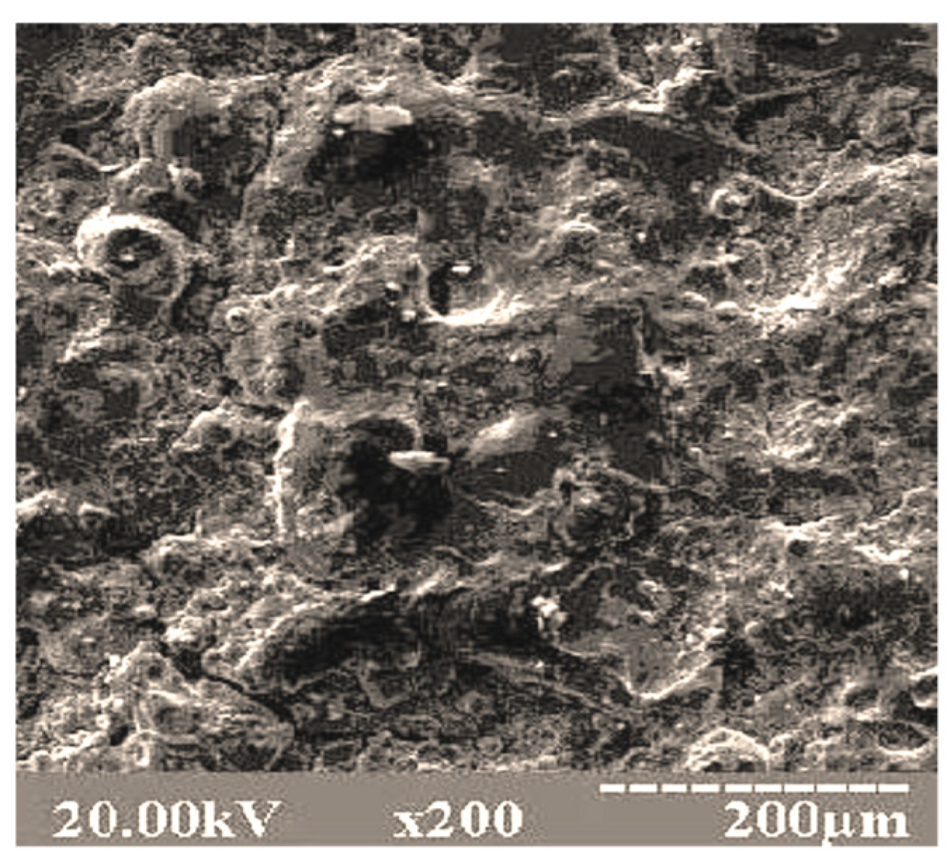
Figure 4 shows the surface area of the graphite coating on the top of the V
2O
5 coating on the matrix of the 15CrMoV5-9 sample. The surface is without cracking the coating. When viewing the morphology of the surface layer, various swellings are observed in the form of a “raised relief”. This is primarily due to the fact that the modification of the surface of 15CrMoV5-9 steel by deposition of the double-layer of various compositions is accompanied by the formation of a fused structure with a scaly layered character. The coating has high relief without sharp protrusions; this is due to the fact that a wide range of powder particle sizes was used: vanadium pentoxide (15–25 microns); graphite (5–14 microns). Therefore, during a flight in a pulsed microplasma stream, particles of smaller powders were completely melted, and particles of larger sizes were only partially melted. Deforming upon impact and filling various microdrops on the substrate surface, they formed a complex relief coating.
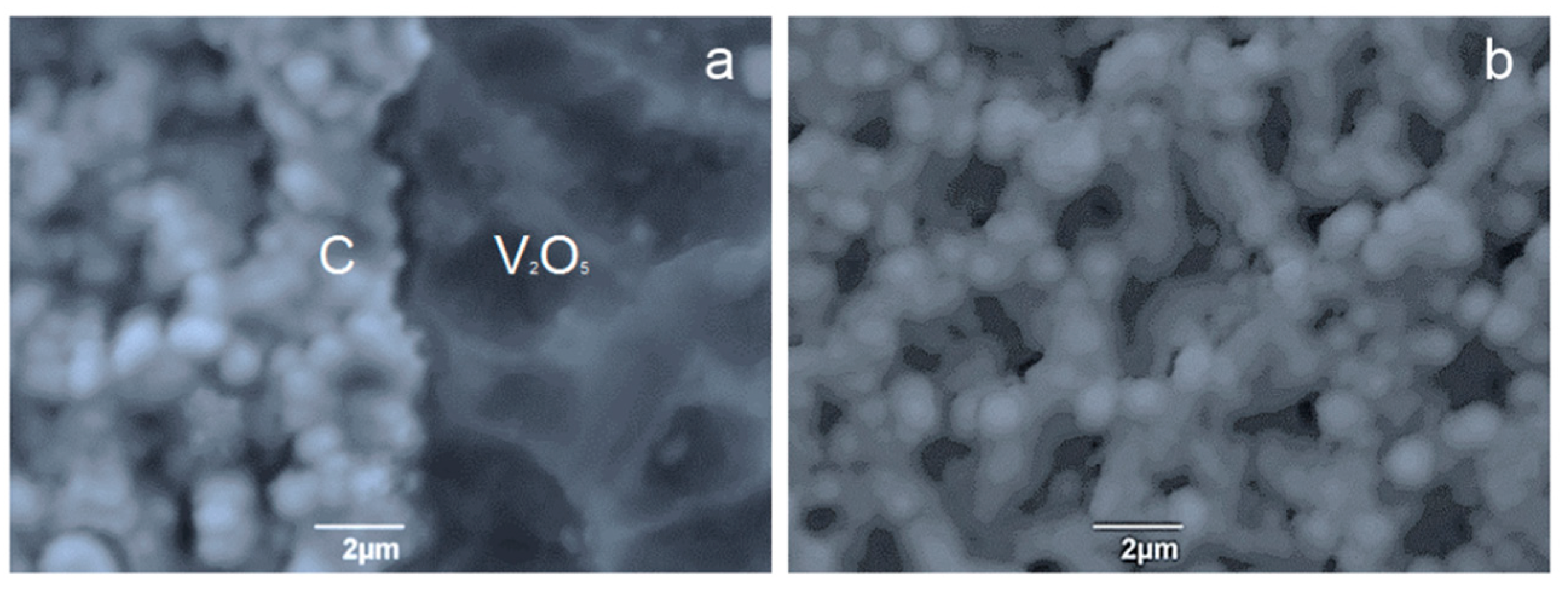
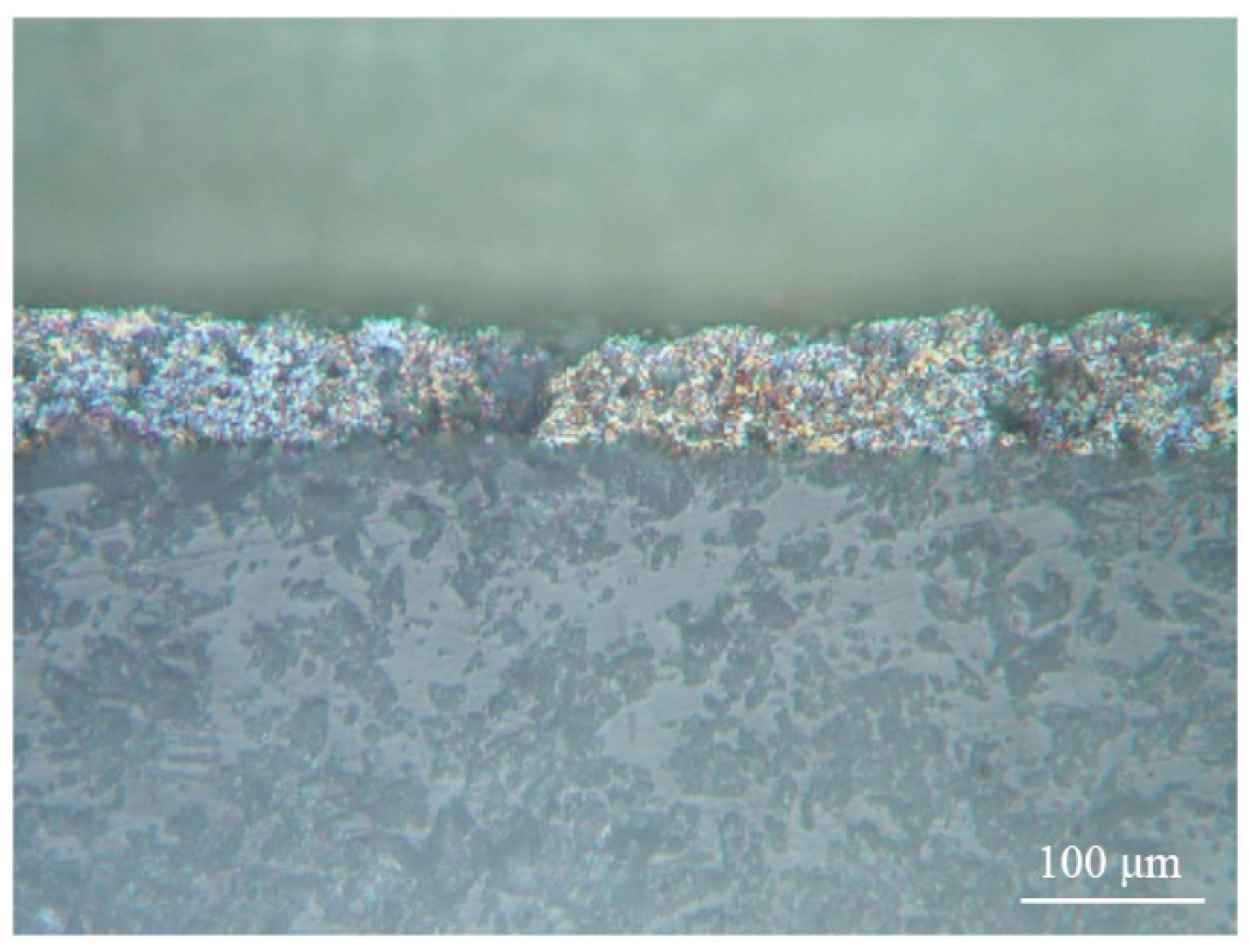
The microstructure of the surface and the cross-section of the coating showed a clear interface between the components of the multi-coating, which appears at the boundary of the graphite/V
2O
5 crystallization front (
Figure 5). Crystallization propagated in a self-sustaining manner throughout the film. The self-sustaining nature of the motion of the crystallization front was apparently determined by the fact that during the crystallization process, at the interface between the two substances, the energy stored in the film was released. In [
25], it has been established that explosive crystallization of films can occur not only as a result of the action of an electron beam, but also during the deposition process at temperatures much lower than the melting temperature, as well as under the influence of mechanical shock.
Figure 6 shows the microstructure of the V
2O
5/C coating on the substrate obtained by transmission electron microscopy.
In the coating structure in
Figure 6, regular structures were formed in the form of branches of dendrites. Such structures should be considered as dissipative, and at the same time, they were approaching the hydrodynamic model of Hele-Schau cells. At the crystallization front, the liquid zone was divided into two sub bands with different viscosity coefficients μ
1 and μ
2. A less viscous liquid phase was pressed into the more viscous amorphous phase.
Presumably, the mechanism of structure formation in the studied films is as follows: As a result of coating in the chamber, crystallization centers appear in it. A shear transformation zone arises at the crystallization front. If the width of the zone does not exceed a few nanometers, then crystallization in the film is explosive with the formation of dendrites. The formation of phases with a high degree of nonequilibrium leads to an increase in the energy of interatomic bonds, for example, for carbon, diamond is such a structure. During the formation of dendritic structures, an increase in fractal dimension leads to an increase in energy due to a significant increase in the surface area of dendrites.
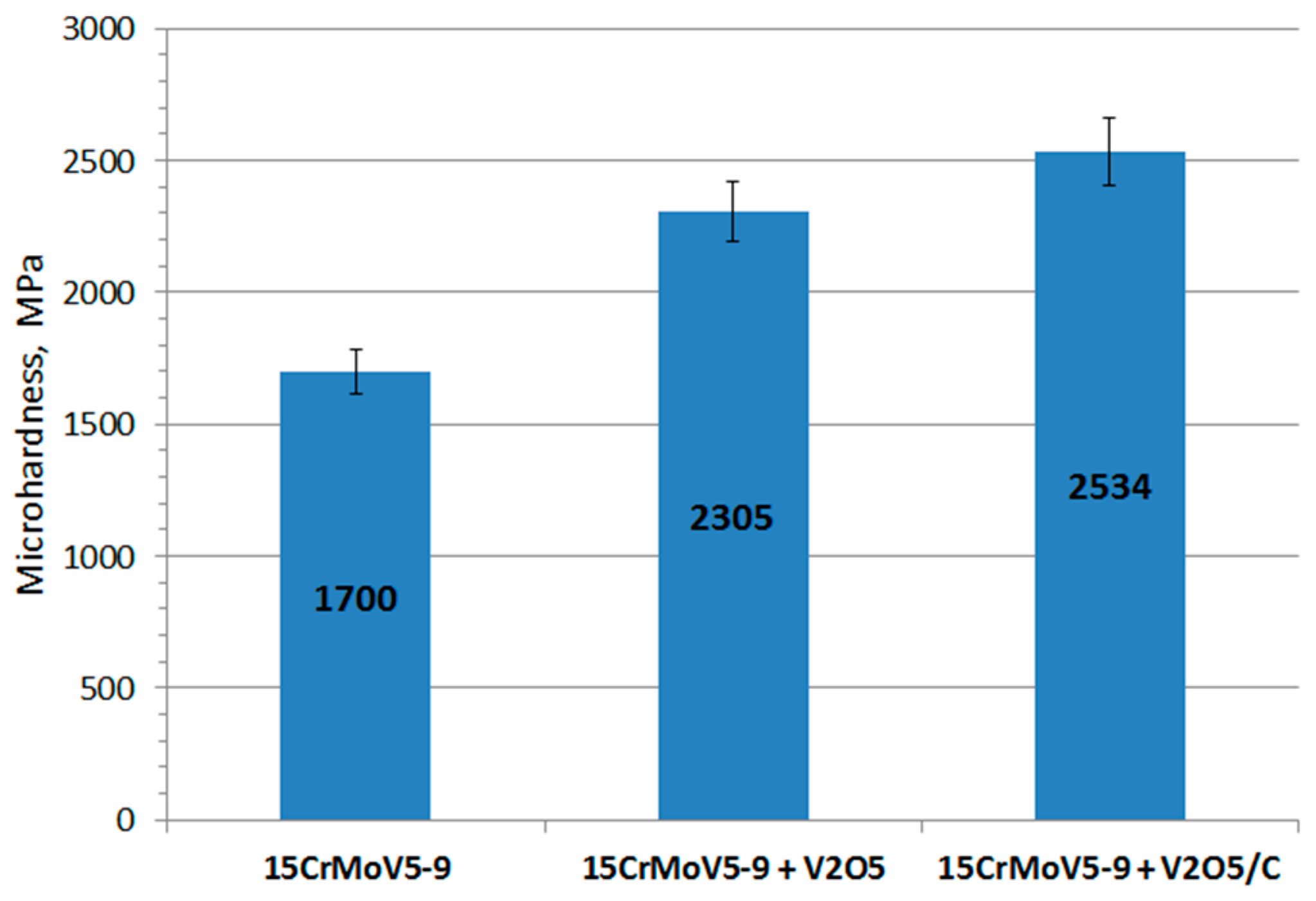
The microhardness of the initial sample of the 15CrMoV5-9 matrix before deposition was at the level of 1700 ± 85 MPa, the vacuum deposition of a thin V
2O
5 film (84.5 μm) and the microplasma graphite deposition increased the microhardness of the initial sample. The sample coated only with V
2O
5 showed microhardness of 2305 ± 115 MPa. The addition of the second layer of graphite (V
2O
5/C) resulted in the increase in microhardness up to 2534 ± 127 MPa, which was 33% higher than that of the initial sample (
Figure 7). The increase in the microhardness is explained by the amorphous structure of graphite, since the coating has no boundaries between grains.
The wear resistance of the initial sample was 0.35 mm
3, and for the sample with a double-layer coating, this was 0.14 mm
3 (
Table 1,
Figure 8).
The wear tests were carried out to compare and prove the effectiveness of the applied coating in improving the tribological characteristics of the samples.
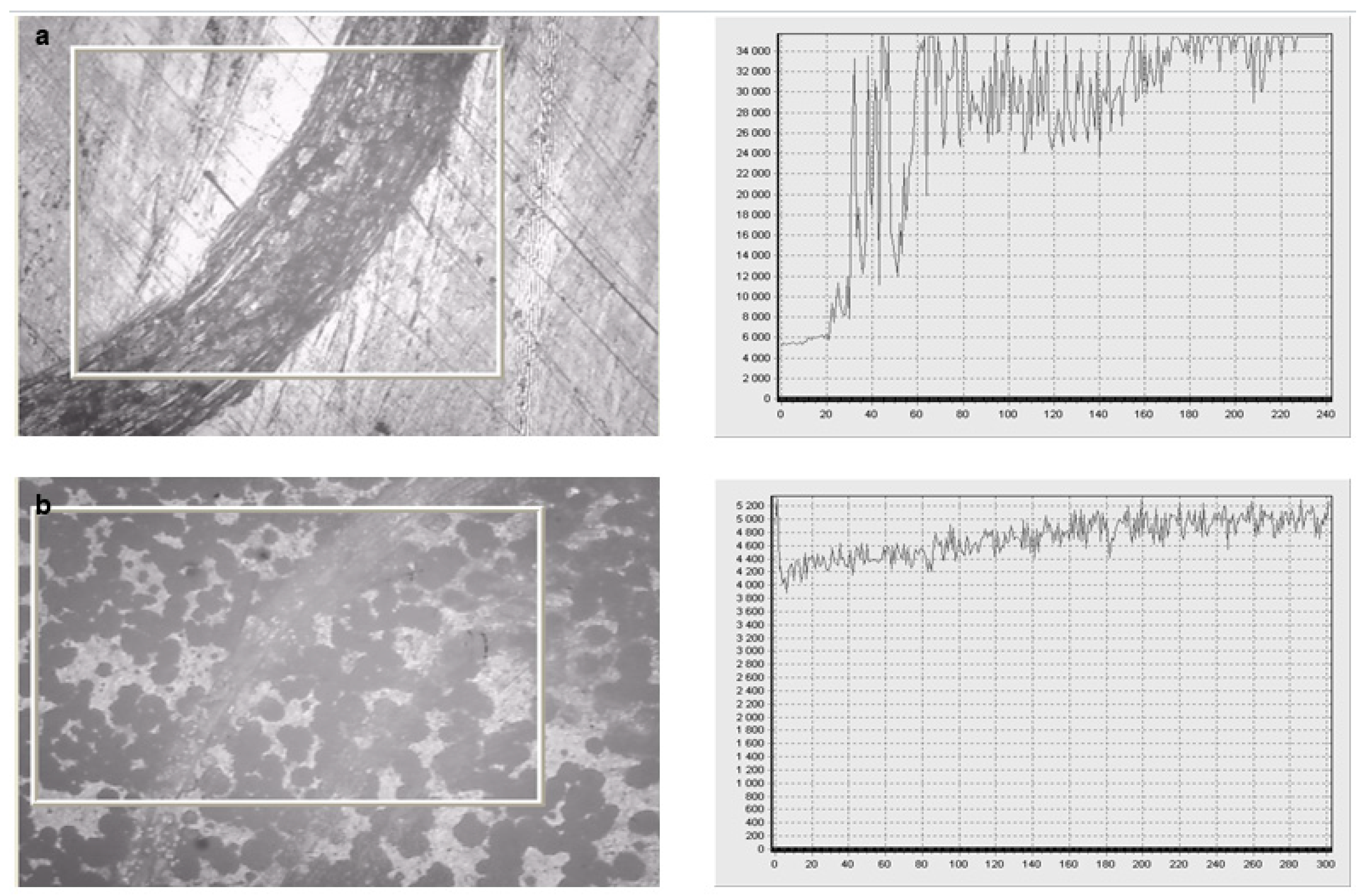
Figure 8 visualizes the difference in surface wear resistance. The track of the friction ball used in the test was much more obvious for the sample without coating indicating that the wear rate for this sample was much higher (8.26 × 10
−4 mm
3·N
−1·m
−1) compared to the sample coated with the V
2O
5/C coating (3.42 × 10
−4 mm
3·N
−1·m
−1). Thus, coating the steel sample with the proposed double-layer V
2O
5/C coating allowed the reduction in the volume loss as a result of wear (wear resistance) by 2.5 times, from 0.35 to 0.14 mm
3.
Tearing tests allowed the determination of the adhesion. The average adhesion strength obtained on the 15CrMoV5-9 alloy with the V
2O
5/C coating was 17.5 MPa (
Table 2).
Figure 9 shows the structure of the coating after adhesion tests. In various places of the coating, there was a variation in adhesion strength. This was due to the difference in the mechanisms of destruction of the coatings under external influences. Since the surface of the substrate was thoroughly prepared, a developed relief with a high tendency to chemical interaction was formed on its surface. The total thickness of the coatings was ~200 μm (84.5 μm V
2O
5/115.4 μm C); therefore, the formation of microcracks occurred on the contact surfaces. This was facilitated by an increase in internal stresses, an increase in porosity, and the appearance of interlayer boundaries. Cracks occurred at the edges of flat pores, which are stress concentrators. The destruction of the coating occurred by the mechanism of the propagation of cracks in the porous material. The surface relief indicated plastic deformation of the coating particles during crack propagation. This can serve as the basis for predicting the high mechanical properties of the coating. In addition, a quantitative assessment of the adhesion of the sprayed coatings (
Table 2) showed that the adhesion strength of the coating corresponded to high adhesion strengths between the coating and the substrate [
26,
27].
Thus, an assessment of the surface after the adhesion test of the coating showed that preliminary ion etching with argon and heat treatment of the 15CrMoV5-9 alloy, as well as the application of an intermediate layer of V2O5 on the substrate, prevented embrittlement of the graphite coating on the substrate and led to the formation of a strong bond at the coating–substrate interface.
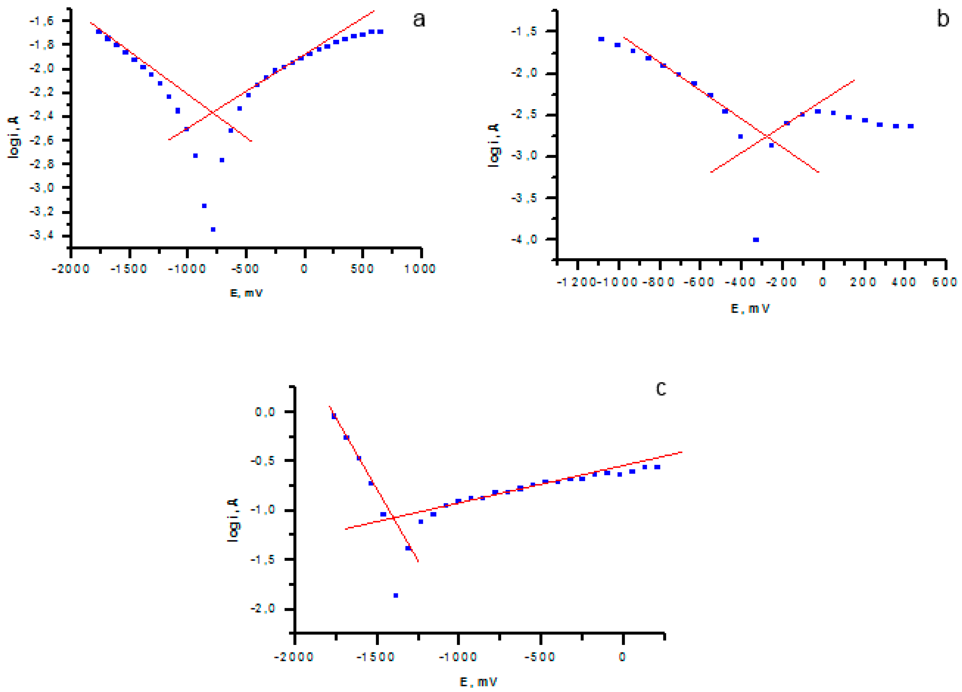
Corrosion properties were evaluated by the potentiostatic method. The logarithmic dependence of the current on the potential is shown in
Figure 10.
The logarithmic dependences showed a twofold decrease in the corrosion rate and the thickness of the corrosion layer after applying the V
2O
5 coating on the sample (
Figure 10b) compared with the uncoated sample (
Figure 10a). The highest corrosion resistance was observed for the sample with a coating of V
2O
5.
The results of the assessment of corrosion properties are presented in
Table 3.
The presented corrosion tests showed the dependence on the coating composition (
Table 3), however, in all cases, applying the V
2O
5 coating significantly reduced the corrosion rate of the sample.
4. Conclusions
According to the results of the study, a surface hardening technology was developed by applying the double-layer microplasma coating V2O5/C for strengthening the blades of the mini-HPP made of low-alloy pearlite 15CrMoV5-9 alloys.
One of the effective ways to increase the durability of coatings, starting from the surface of the protective coating, through its entire thickness to the substrate itself, is to create multi coatings with a certain morphological component of regular structures in the form of dendrite branches.
The preliminary heat treatment and the final stage of the combined coating process of forming the multilayer containing both V2O5 with a low shear resistance and carbide particles of high hardness can increase the overall hardness, wear resistance, and corrosion resistance of the coating, which are important performance characteristics to increase the life of individual mini-HPP nodes. In addition, the presence of the protective coating on the parts can help to stop the constant ablation of the base metal from the surfaces of the blades as a result of hydroabrasive wear.
The microplasma method of applying a double-layer composite coating to the metal matrix can find application in the surface treatment of products of power equipment to improve their operational characteristics.
