1. Introduction
Sn-based alloys, also known as Babbitt or white metal, represent a group of alloys that contains different grades of Sn with the addition of Cu and Sb. The addition of Cu and Sb, inter alia, determines the strength of the materials. Sn–Sb–Cu-based Babbitt alloys mainly consist of a soft solid solution matrix interstratified with intermetallic phases, such as SnSb and Cu
6Sn
5 [
1]. The formation of Cu
6Sn
5 or Cu
3Sn in part results from the interaction of Cu with liquid Sn. Cu
3Sn usually arises from the formation of Cu
6Sn
5 [
2], wherein the formation of Cu
3Sn necessitates an increased Cu content and higher temperatures. For common Cu contents, however, the formation of Cu
3Sn is less likely. At 186 °C, Cu
6Sn
5 reveals an allotropic transformation from a monoclinic crystal structure at lower temperatures to a hexagonal crystal structure at higher temperatures [
3]. The hexagonal phase can be stabilized with the addition of further elements [
4]. Thus, the inclusion of small amounts of Sb leads to the formation of Cu
6Sn
5−xSb
x and shifts the region of thermal stability from 186 °C down to room temperature. Nevertheless, it was found that high concentrations of Sb cause multiple agglutinations of SbSn crystals in the matrix [
5], while high concentrations of Cu favor the emergence of Cu–Sn intermetallic compounds, which simultaneously leads to a reduced toughness [
6]. Further alloying elements can be used to obtain a microstructure refinement, i.e., Sb–Sn and Cu–Sn intermetallic precipitates. Together with solid solution hardening effects, the refinement can cause improved mechanical properties [
7].
Babbitt coatings are widely used in industrial bearings. Therefore, Babbitt coatings serve as a sacrificial surface [
8]. In the event of unwanted contact with the more expensive counterpart, the softer Babbitt surface wears out to protect the counterpart from significant damage [
9], or to permit deformation to accommodate some misalignment of the bearing surfaces [
10]. Moreover, the soft solid solution matrix provides the ability to act as a solid lubricant and allows the embedding of abrasive particles, whereas the intermetallic phases dispersed in the matrix largely determine the resulting hardness and thus have a substantial influence on the maximum load carrying capacity [
11].
In the field of thermal spraying, Babbitt coatings are commonly deposited by using flame spraying [
12], plasma spraying [
13], high velocity oxy-fuel spraying [
9] and arc spraying [
12]. To date, only a very few studies have paid attention to Sn–Sb–Cu-based Babbitt coatings deposited by means of LPCS and reported the microstructural properties. For instance, Vale-Júnior et al. [
14] investigated the feasibility of manufacturing an Sn–Sb–Cu-based anode material processed by LPCS and evaluated its potential application for electrochemical treatments. A patent by Lamberton et al. [
15] disclosed a cold spray coating process for depositing a powdered Babbitt material on the inner surfaces of a bearing assembly. However, no information on the microstructure was provided by the authors. In general, LPCS can be assigned to cold spraying. In comparison to other thermal spraying techniques, cold spraying is characterized by the utilization of low process temperatures with high spray particle velocities. In cold spraying, the propellant gas is accelerated to supersonic velocities in a de Laval-type nozzle, i.e., a converging–diverging nozzle [
16]. During coating deposition, spray particles with high kinetic energy impinge onto the substrate, deforming and generating a coating. The temperature of the propellant gas is below the melting point of the feedstock, thus largely avoiding phase transformation processes. Cold spraying can be divided into two processes: (i) LPCS and (ii) high pressure cold spraying. The distinction results from technical details and common equipment variants that arise from handling of lower pressures, or predominantly high pressures. The distinction between the two processes including typical spray parameter settings are summarized in [
17,
18]. In short, for depositing coating using LPCS, the propellant gas is heated only in the spray gun instead of a separate heating unit. The feedstock is injected in the diverging part of the nozzle from where particles are accelerated towards the substrate. The temperature of the propellant gas (helium, nitrogen or air) is commonly up to 650 °C, with the working temperature range for low-melting materials usually being in the range of 300 to 500 °C [
19]. The spray particle velocities are in the range of 350 to 700 m/s [
20]. A major challenge in LPCS using metallic feedstocks is nozzle clogging, which can become more severe as spray particle velocity and temperature are increased. To overcome this issue, a blended powder is commonly used, which additionally contains ceramic hard particles (e.g., alumina) [
21]. From an environmental and economic perspective, LPCS represents a cost-saving method without the usage of fuel gases or liquid fuels, with the ability to recondition or repair coatings of worn surfaces, even on site, directly on the customer’s premises since the spray equipment is transportable.
In this study, Sn–Sb–Cu-based coatings produced by LPCS were investigated with respect to their microstructural characteristics. Different preheating gas temperatures and substrate preheating temperatures at a number of variations were analyzed along with their interaction with the resulting phase composition, distribution of intermetallic compounds, microhardness, and mesoscopic coating structure.
2. Materials and Methods
2.1. Coating Deposition
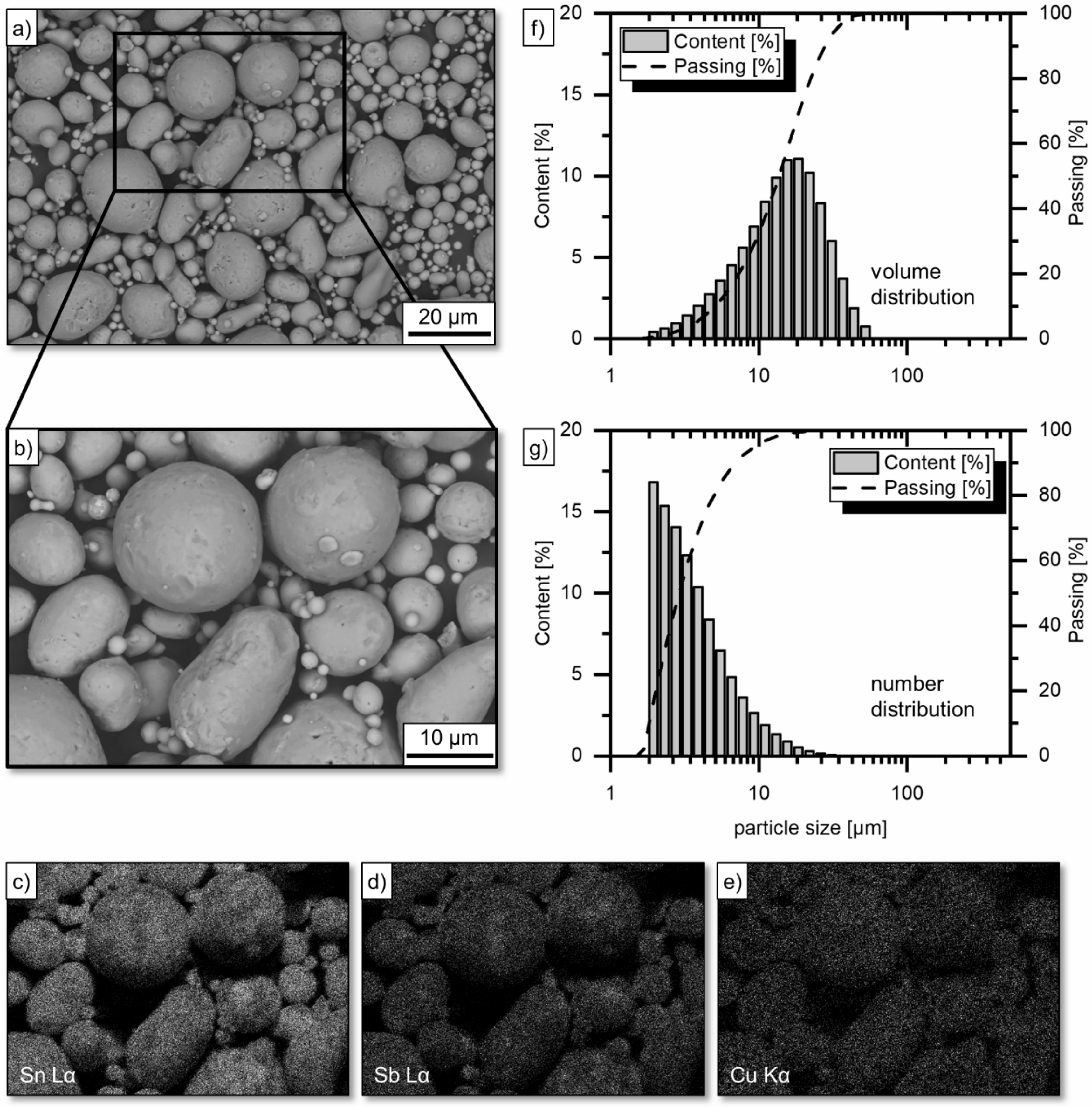
In this study, coin-shaped (40 mm × 5 mm) AISI 1045 steel specimens served as substrates. Prior to the coating deposition, the substrates were grit blasted using corundum with a grit size of F100, according to the Federation of European Producers of Abrasives. The substrates were afterwards soaked in an ultrasonic ethanol bath for ten minutes to remove oil residues and contaminations. A gas atomized Sn–Sb–Cu-based powder (B-83-100-40, Dycomet, Akkrum, The Netherlands) served as feedstock. According to the manufacturer, the powder contains ≥75 wt.% of Sn, 10–25 wt.% of Sb and 2.5–10 wt.% of Cu. Scanning electron microscope (SEM) imaging, as well as the corresponding energy dispersive X-ray spectroscopy (EDS) maps obtained from Cu Kα, Sn Lα and Sb Lα, show the morphologies of the different powder particles and the distribution of element concentrations (
Figure 1a–e). The powder particles mainly exhibit a spherical shape. A small number of particles reveal some attached satellite particles (i.e., smaller solid particles). As verified by laser light scattering (particle analyzer S3500, Microtrac MRB, Montgomeryville, PA, USA), the sampling demonstrates a 50th percentile (D50) of 13.70 µm with respect to the volumetric particle size distribution, while the 10th percentile (D10) and 90th percentile (D90) is 5.07 and 27.78 µm, respectively (
Figure 1f). In correspondence with the SEM images, the number distribution of particles also shows a significantly high number of small particles (D10: 1.83 µm, D50: 2.89 µm; D90: 6.95 µm,
Figure 1g).
Prior to the coating experiments, the feedstock was homogenized using the TURBULA T2F mixer (Willy A. Bachofen, Muttenz, Switzerland) for 30 min. The spraying experiments were carried out with the use of oil-free compressed air and the DYMET 413 spraying system (Dycomet, Akkrum, The Netherlands). The powder was injected radially into the gas jet at the diverging part of a de Laval-type nozzle. The divergent section length of the nozzle was 120 mm, while the round-shaped inlet and outlet diameter were 4.0 and 4.8 mm, respectively. The preheating gas temperature (PGT, i.e., temperature of the propellant gas), as well as substrate temperature (ST), were varied at a number of variations (
Table 1). As shown in
Table 1, 400 °C was selected as the maximum temperature for PGT. Preliminary tests showed that with further increase in gas temperature, i.e., 450 and 500 °C, processing was not possible due to nozzle clogging, leading to an immediate process interruption. A thermocouple was used to evaluate the gas temperatures at the nozzle exit prior to the coating deposition. The substrates were heated on a hot plate before depositing coating. The temperature was maintained until coating by the use of a heat gun. The ST was evaluated at the substrate surface prior to the first overrun of the spray path using a VOLTCRAFT IR-1000L infrared thermometer (Conrad Electronic, Hirschau, Germany). For depositing the coating, the spray gun was mounted on a six-axis robot IRB4400 (ABB, Zürich, Switzerland). The coating was produced using a spray distance of 15 mm, a transverse speed of the spray gun of 100 mm/s and a track pitch of 2 mm for the meander-shaped spray path. One overrun was conducted in order to achieve an adequate coating thickness, as well as to provoke a maximum influence of the ST on the microstructure generated. In order to inject the feedstock into the process, an external powder feeder system of type Single 10C (Plasma-Technik, Wohlen, Switzerland) was utilized. As verified by gravimetrical measurements, the powder feed rate was 41 g/min (according to a carrier gas pressure of 0.3 MPa using nitrogen, and the feeder disk velocity of 15%).
2.2. Analytic Methods
The phase composition was investigated at the ground coating surface by means of X-ray diffraction (XRD). The machining was conducted using different SiC grinding papers, involving P80, P320, P600 and P1200 grit sizes, according to the Federation of European Producers of Abrasives. The XRD experiments were carried out at the beamline BL9 [
22] of the synchrotron light source DELTA (Dortmund, Germany). The photon energy was set to 15 keV (wavelength λ = 0.8265 Å). A PILATUS detector system (Dectris, Baden, Switzerland) was used to measure the scattered intensity. The beam size was set to 1.5 × 0.1 mm² (horizontal × vertical), and the angle of the incidence was 5°. The software MATCH! in conjunction with a reference database (i.e., Crystallography Open Database) was used to identify the phase composition.
Mesoscopic coating characteristics were metallographically investigated through cross-section analyses. Therefore, cross-sections were separated from ground coated samples. The embedded cross-sections were afterwards metallographically prepared using silicon carbide grinding discs and polishing cloths with diamond suspension (abrasive particle size: 6, 3 and 1 µm). Cross-section images were taken by using the optical microscope Axiophot (Carl Zeiss, Oberkochen, Germany). The samples were further subjected to chemical etching in a 0.25% solution of hydrochloric acid in distilled water. Etched cross-sections were studied in reflected light using the optical microscope (see above). Cross-section images at higher magnifications were taken by scanning electron microscopy using a field emission scanning electron microscope (FE-SEM) (type JSM-7001F, Jeol, Tokyo, Japan) equipped with secondary electrons (SE), backscattered electrons (BSE) and energy dispersive X-ray detectors (Oxford Instruments, Abingdon, UK). In conjunction with the FE-SEM, EDS was conducted in order to investigate the element distribution. The data was analyzed with the EDS microanalysis software INCA (Oxford Instruments, Abingdon, UK).
In terms of the mechanical properties, the microhardness of the low pressure cold sprayed Sn–Sb–Cu coating was measured at the cross-section by Vickers microhardness measurements with a load of 0.49 N (0.05 kp) using a Duramin-40 microhardness tester (Struers, Willich, Germany). A minimum of five indents were conducted for the microhardness measurement. To preclude size effects (i.e., individual phases, or defects), the remaining indents were afterwards evaluated by means of optical microscopy. The coating adhesion was analyzed by determining the tensile bond strength (pull-off test) according to DIN EN 582. Cylindrical AISI 1045 steel samples with a diameter of 25 mm were grit blasted, cleaned and coated using the same sample preparation and spraying parameter settings as for the coating (see before). The adhesion tests were conducted utilizing the epoxy resin adhesive HTK ULTRA BOND 100® (HTK Hamburg, Hamburg, Germany). The tensile load was applied by using a universal testing machine (Mohr and Federhaff, Mannheim, Germany). The mean value of tensile bond strength was calculated, taking into account six samples for each spray parameter setting.
3. Results
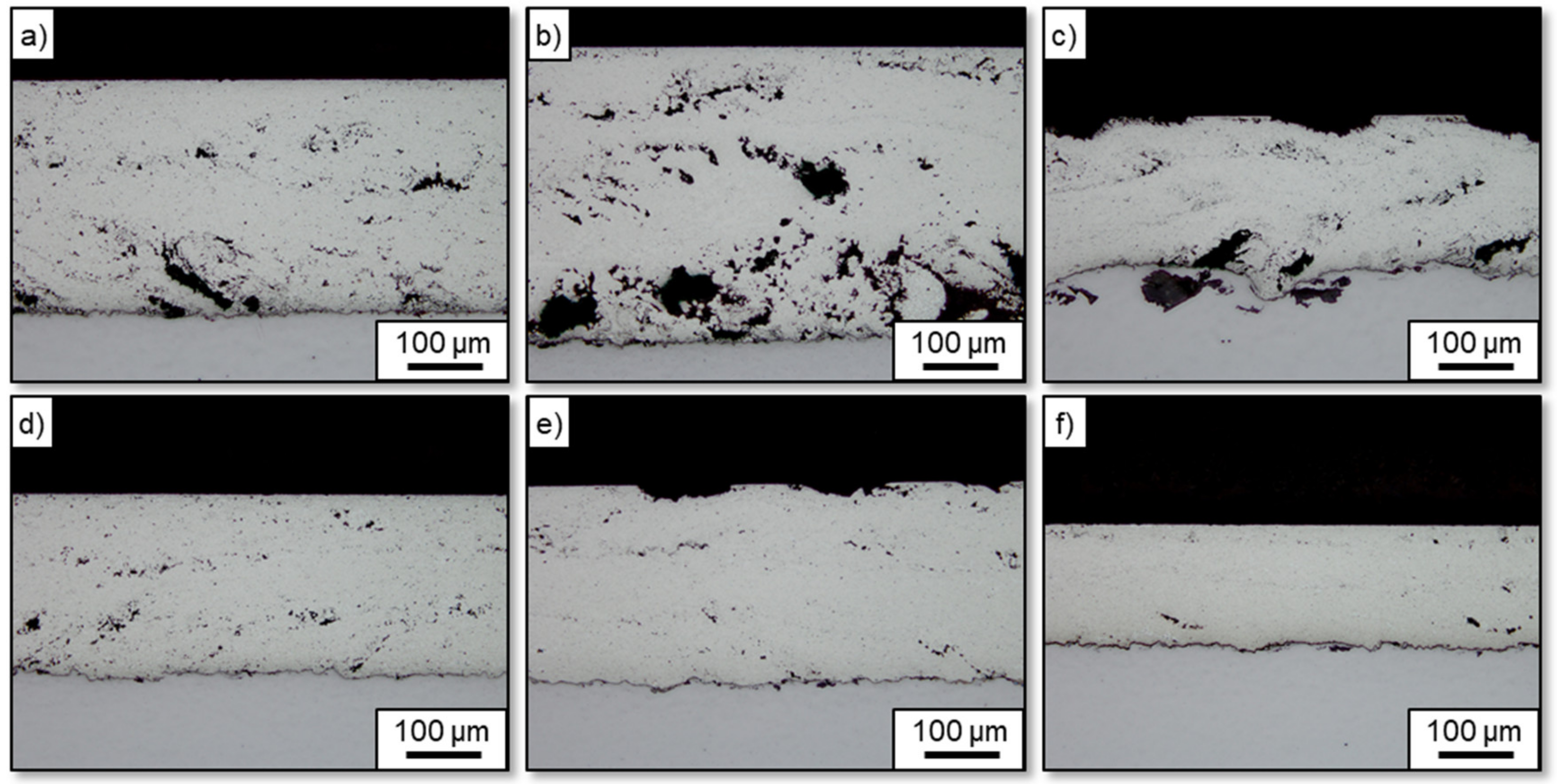
Figure 2 shows the coating microstructure at the cross-section as obtained from the coating deposition using different PGT (i.e., 300, 350 and 400 °C), depending on the ST. For an ST of 20 °C (i.e., room temperature), it was found that the produced Sn–Sb–Cu-based coatings exhibited a high amount of porous zones, which predominantly occurred next to the coating–substrate interface (
Figure 2a–c). Such cluster-like pores had a size of 50 to 100 µm and were partly elongated with a preferred orientation of approximately 45°. Phenomenologically, such defects occurred randomly along the entire coating. A specific frequency could not be identified. For an ST of 260 °C, the coatings were deposited by using a PGT of 300, 350 and 400 °C. They hardly showed any such defects (
Figure 2d–f). In this respect, the coatings demonstrated a dense microstructure with an overall porosity of less than 2.6%.
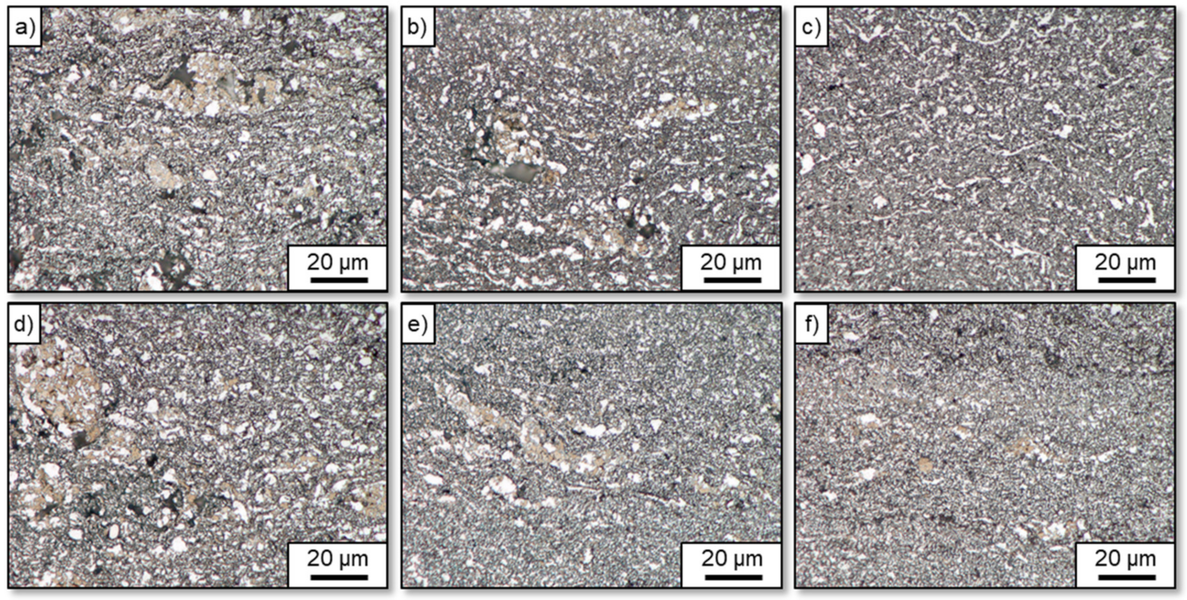
Figure 3 shows the coating microstructure as obtained from different PGT and ST after etching. The contrast shows that a fine-structured polygonal phase (bright phase) was distributed across the entire coating and was surrounded by a dark matrix (dark gray phase). Such a structure could be observed for all samples. Furthermore, partially island-like structures (bronze colored phase) were visible and appeared more dominant at reduced PGT (
Figure 3a,d).
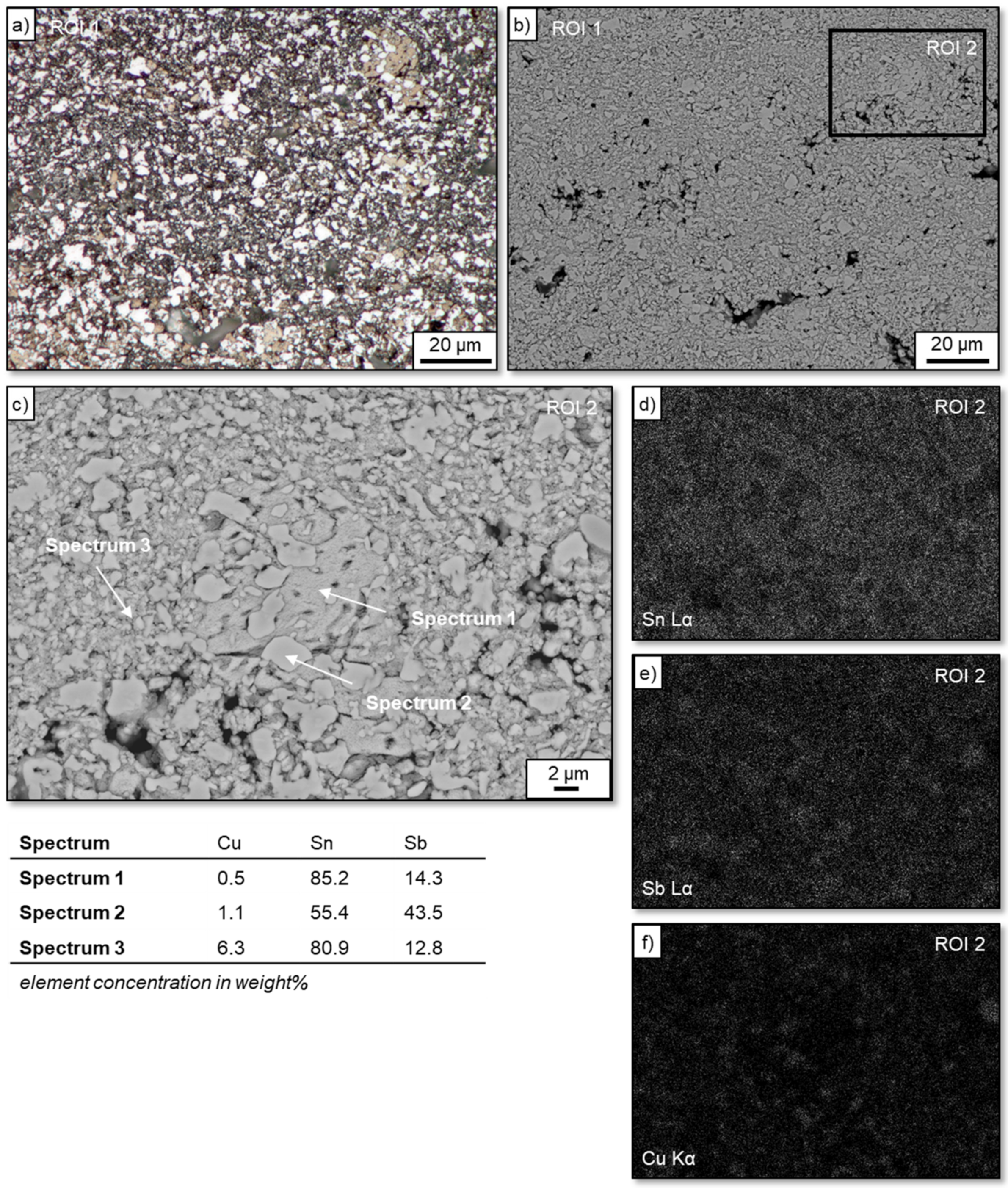
Figure 4a,b show a light micrograph and the corresponding BSE imaging of the coating microstructure in a magnified view after etching (i.e., PGT: 350 °C, ST: 20 °C). For the region of interest (ROI) 1, the different microstructure features (as visible as bright phase, dark gray phase and bronze colored phase) are clearly noticeable.
Figure 4c shows an enlarged view of striking microstructure features (i.e., ROI 2) including the bronze colored phase and its surroundings. For the ROI 2, the corresponding EDS maps obtained from Sn Lα, Sb Lα and Cu Kα indicated a heterogeneous microstructure. Thus, the EDS counts showed that the microstructure comprised a mixture of Sn–Sb-rich phases. Individual spots of the Sn–Sb-rich phases differed in their elemental concentrations (i.e., Sn and Sb concentrations). Moreover, the EDS maps suggested the presence of Cu–Sn–Sb-rich and Cu–Sn-rich phases. EDS spot analysis (
Figure 4c, spectrum 3) pointed to a solid solution of Cu, Sn and Sb for the surrounding matrix (dark gray phase). On the contrary, EDS spot analysis of polygonal particles (
Figure 4c, bright phase, spectrum 2) suggested a mixture of Sn and Sb with an almost equal atomic ratio, leading to an assumed intermetallic phase. Spectrum 1 (
Figure 4c), which corresponds to the bronze colored phase, as seen in
Figure 4a, indicated a high amount of Sn in the Sn–Sb-rich phase. For spectrum 1 and 2, some minor concentrations of Cu could be detected (which was probably due to the experimental resolution).
As obtained from the XRD patterns, the coatings either produced by using different PGT or ST mainly consist of Sb
2Sn
23 [
23], Sb
0.49Sn
0.51 [
24] and Sorosite (CuSn or CuSb
0.115Sn
0.835) [
25] (
Figure 5). There was no evidence for the formation of Cu
3Sn and monoclinic Cu
6Sn
5 within the experimental resolution. In comparison with the feedstock, no phase transformation processes could be identified after LPCS.
In terms of the Vickers microhardness measurement, it could be seen that an increased PGT led to an increased microhardness of the Sn–Sb–Cu-based coating (
Table 1). At a PGT of 300 °C (ST: 20 °C), the Sn–Sb–Cu-based coating demonstrated a microhardness of 31.3 ± 0.7 HV0.05, whereas at a PGT of 350 °C (ST: 20 °C), the deposit exhibited a microhardness of 35.5 ± 0.8 HV0.05. A further increase in PGT (PGT: 400 °C; ST: 20 °C) resulted in a microhardness of 45.7 ± 2.1 HV0.05. The same tendency could be found for the Sn–Sb–Cu-based coatings deposited on a ST of 260 °C. Evaluation of the remaining indents showed that the indents were positioned on a nearly defect-free microstructure (i.e., dense area), thus precluding the influence of size effects, or irregularities, such as pores or cracks. XRD analyses showed an almost identical phase composition for all samples, which also corresponded to the starting powder (feedstock). Accordingly, no interrelationship between the increase in hardness above 300 °C and the phase composition could be established. In contrast, the cross-section analyses (
Figure 3) suggested that the increase in microhardness at elevated PGT was likely correlated with a more homogeneous distribution of Sb
0.49Sn
0.51 dispersed in the soft Sn-rich solid solution matrix.
Regarding the coating adhesion, the tensile bond strength for the different coatings was found to be in the range between 6.1 and 9.5 MPa (
Table 1), which was low in comparison to the results given in the literature [
21,
26]. It is assumed that the low values resulted from the non-use of ceramic hard particles in the feedstock. Koivuluoto et al. [
21] demonstrated that bond strength of low pressure cold sprayed coatings distinctly depends on the amount of alumina in the powder mixtures. Accordingly, the bond strengths increased with increasing amount of alumina particles. Moreover, there were no distinct differences in tensile bond strength among the different samples. In all cases, the fracture was found to be at the coating–substrate interface, indicating a poor bonding between the low pressure cold sprayed Sn–Sb–Cu coating and the steel substrate (note: the bond strength of the adhesive HTK ULTRA BOND 100
® was measured at approximately 104 MPa). For the spray parameter settings used in this study, it can be concluded that the PGT and ST have no substantial effect on the coating adhesion.


