Article

Effect of Laser Processing on Surface Properties of Additively Manufactured 18-Percent Nickel Maraging Steel Parts

1
Department of Mechanics and Materials Engineering, Vilnius Gediminas Technical University, LT-10223 Vilnius, Lithuania
2
Laboratory of Composite Materials, Vilnius Gediminas Technical University, LT-10223 Vilnius, Lithuania
3
Laboratory of Materials Research, Vilnius Gediminas Technical University, LT-10223 Vilnius, Lithuania
4
Center for Physical Science and Technology, LT-02300 Vilnius, Lithuania
*
Author to whom correspondence should be addressed.
Coatings 2020, 10(6), 600; https://doi.org/10.3390/coatings10060600
Submission received: 1 June 2020 / Revised: 20 June 2020 / Accepted: 24 June 2020 / Published: 26 June 2020
(This article belongs to the Section Surface Characterization, Deposition and Modification)

Abstract

:
In the present work, the experimental study on laser processing of additively manufactured (AM) maraging steel part surface was conducted. Nanosecond pulsed laser at ablation mode was used for surface modification in oxidizing atmosphere. The morphology, roughness, elemental and phase composition, microhardness and tribological properties of the processed surfaces were investigated. The obtained results revealed that pulsed laser processing under the ablation mode in air allows obtaining modified surface with uniform micro-texture and insignificant residual undulation, providing 3 times lower roughness as compared with the as-manufactured AM part. The intensive oxidation of surface during laser processing results in formation of the significant oxides amount, which can be controlled by scanning speed. Due to the presence of the oxide phase (such as Fe2CoO4 and Ti0.11Co0.89O0.99), the hardness and wear resistance of the surface were significantly improved, up to 40% and 17 times, respectively. The strong correlation between the roughness parameter Ra and mass loss during the tribological test testifies the significant role of the obtained morphology for the wear resistance of the surface.

1. Introduction

Additive manufacturing (AM) is the general name for technologies that forms 3D parts from the digital model by adding of materials (plastic, metals, etc.) layer-by-layer. Initially AM was developed for rapid prototyping of new products. Great improvement was reached in AM technologies over the last thirty years and now AM is already used for direct production of end-use parts [1]. For metal parts production by AM, two major technologies were developed—powder bed fusion based technologies (PBF) and directed energy deposition (DED) based technologies [2]. Selective laser melting (SLM) is one of the main representative processes of PBF based technologies. SLM uses laser energy for selective melting of the powder to produce three-dimensional object. Part of it is produced “cross-section by cross-section”. Each laser-scanned cross-section is generated from a 3-D digital description of the part [3]. The current level of metal SLM technologies allows producing dense metallic parts with geometric tolerance between 50 and 100 μm [2]. Due to the possibility to produce the parts with complex internal and external geometries, SLM attracts growing interest in various fields of engineering including aircraft, aerospace, biomedical, automotive, marine industries and tooling, where maraging steels find broad application [4,5,6,7,8,9]. Using the SLM technology allows one to realize difficult geometry of cooling channels within the tooling (die, mold, forging and cutting tools).
Maraging steels are a special class of high-strength steels possessing high yield strength (up to 2420 MPa for commercial grades) combined with high fracture toughness and ease of fabrication [4,10]. The specific alloying system provides highly alloyed low-carbon iron-nickel quite soft (30 HRC) lath martensite matrix, which is aged (annealed) to obtain hardening by intermetallic precipitation [4,11]. The hardness of intermetallic compounds is not extremely high, as compared with borides, carbides and some oxides; therefore, maraging steels possess moderate hardness (58 HRC max.) and, as a result, insufficient wear resistance. As was found as far back as the 60s, gas nitriding is a suitable process enabling considerable surface hardening of maraging steel [6,12,13,14,15,16]. The typical steel nitriding temperatures (450–500 °C) are close to those required for aging of maraging steels; therefore, both the nitriding and aging processes can be accomplished simultaneously [4]. The main disadvantage of the gas nitriding process is long duration of the process—approximately 10 h for obtaining 0.1 mm layer employing one step process or 1.5–2 times shorter duration when two-step nitriding process is applied. Respectively, the energy consumption and production cost are comparatively high.
At the same time, laser surface processing of metals is known as a very flexible method enabling melting and oblation of surface [17] (pp. 295–347). Melting of surface results in its smoothening due to relocation of molten metal under gravity and surface tension. Laser remelting process based polishing of the SLM part could be valuable technique in the cases when mechanical finishing of parts is limited due to complex part geometry. Successful application of laser processing for polishing of SLM parts produced from various alloys (Fe–Co, CoCr, Ti–6Al–4V, TiC11, Inconel 718 and AISI 420 steel) is reported in a number of works [18,19,20,21,22,23]. It is revealed that laser processing not only reduces significantly the roughness of AM parts surfaces and seals porosity, but also refines microstructure, increases their microhardness and wear resistance. According to [24] decreasing the surface roughness improved fatigue performance of SLM steels. When the ablation mode is applied, metal evaporates, sublimates, or is converted to plasma. The interaction of heated surface materials with surrounding atmosphere results in formation of the new compound, for example, oxides (at the presence of oxygen) or nitrides (in nitrogen containing atmospheres) [25,26]. Thus, the surface composition can be modified (therefore, the process is also called “laser gas alloying”) to obtain, for example, higher hardness. From this point of view, the development of laser surface modification methods for maraging steel parts seems to be very promising. Unlike laser polishing, laser alloying of AM surfaces has not been studied extensively. To the best of authors’ knowledge, at the moment, there are no data on the laser modification of as-manufactured maraging steel AM parts.
The present work attempted to evaluate the possibility to obtain surface hardening effect of 18-percent nickel maraging steel (300) SLM part by laser processing at air atmosphere. For this research, SLM samples were produced in a same manner and using the same process parameters as for producing the real end-use products for industry. The laser processing of SLM parts’ surface was performed in air—the cheapest process, which does not require additional vacuum equipment and gas supplying. To intensify the surface material interaction with air oxygen, the ablation mode was chosen. In our earlier publication [27] we presented results obtained on lateral surfaces of SLM specimens. As was found, the roughness had tendency to diminish and hardness had tendency to increase when rising the laser power and slowing the scanning speed. Resulting effect of these properties predetermined visible improvement in wear resistance. The XRD analysis revealed formation of oxides. It was determined as well that the morphology and roughness parameters of lateral and top surfaces of as-manufactured SLM parts differed significantly (for example, Ra parameter was 9.2 and 17.9 μm, respectively). This peculiarity of the SLM process is well known and reported in a number of other works as well. The interaction of a laser beam with the material surface in a large degree predetermined by the part surface condition including surface chemical composition and topography [17] (pp. 91–93). Therefore, it was expectable that the final effect of the laser processing of lateral and top surfaces could differ visibly as well, especially in term of obtained surface topography. Thus, the study was continued with aim to evaluate the effect of laser processing on top-surfaces and the obtained results extended the findings regarding possible effects of applied surface modification technique on the surface properties of maraging steel SLM details. This part of study was focused on the investigation of top-surfaces of SLM specimens and presents the results on obtained surface composition, hardness and tribological properties. Since obtained dependencies differed from that presented in our previous publication, especially in term of morphology, the expanded data on results of morphological analysis and roughness is presented here as well.

2. Materials and Methods

2.1. Materials for Samples Manufacturing

For a formation of the specimens, 1.2709 steel powder was used (0.03% C; <0.1% Si; <0.1% Mn; (17–19)% Ni; 4.8% Mo; <0.8% Ti; (8.5–9.5)% Co and <0.1% Al; Fe-balance). This steel also known as 18Ni300 maraging steel is one of the most widely used and commercially available maraging steels. The morphological analysis (from scanning electron microscope micrographs made using magnification from ×500 to ×3000, see cl. 2.4.) of the powder for selective laser melting showed that the size of particles varies between 7 and 30 μm. Particles of the powder are of near-spherical shape (Figure 1).

2.2. SLM Process Details

For the production of specimens by the SLM process, Concept Laser M3 equipment (Concept Laser, Lichtenfels, Germany) was used. The main characteristics of the equipment and process parameters are listed in Table 1. The square prism specimens with dimensions 15 mm × 15 mm × 10 mm were manufactured. The produced volumes were separated from the substrate (made of the same steel grade) by electric discharge cutting method using the wire spark erosion machine Charmilles Cut 200 (GF Machining Solutions, Geneva, Switzerland). Separated specimens were cleaned in an ultrasonic bath in C3H8O solution for a 15 min at 40 °C temperature.

2.3. Surface Laser Processing Details

For laser processing of the SLM specimens surfaces, a nanosecond pulse laser Baltic HP was used (crystal matrix YVO4; Nd; wave length—1064 nm; power—up to 20 W; pulse frequency—5–100 kHz and pulse duration—10 ns). The minimum power density required to reach melting or evaporation temperature of the material surface by a laser in the pulse mode can be calculated according to the following Equation (1) [28]:
P d = k ( T e T 0 ) π 2 A a   t p
where Pd is the critical power density (W∙m−2); k is the thermal conductivity (W∙m−2∙K−2); Te is the material melting or evaporation temperature; T0 is the initial material temperature; A is the absorptivity; a is the thermal diffusivity (m2·s−1; can be calculated by formulae a = kcp; cp is the specific heat (J·kg−1·K−1)); ρ is the density (kg·m−3)); tp is the duration of laser pulse (s). For 18Ni300 steel, the value of Pd, calculated by Equation (1), is equal to 5.98 × 10¹¹ W∙m−2. The following material physical properties and other parameters were used for calculation: k = 21 W∙m−2∙K−2 at room temperature [5]; Te = 3134 K (taken value for pure iron); T0 = 291 K (room temperature); A = 0.37 [29]; a = 5.71∙10−6 m2·s−1; cp = 460 J·kg−1·K−1 [30]; ρ = 8000 kg·m−3 [5] and tp = 10−8 s.
At the constant other processing parameters, the power density will decrease with increasing laser spot size because of the less energy concentration; the penetration depth will decrease as well. Moreover, it was shown in [31] that surface roughness parameters such as Ra and Rz tend to decrease linearly with rising the laser spot size until reaching some stable value.
In the present investigation, the chosen laser spot size was 25 μm; the step between adjacent laser passes was 18 μm providing appropriate overlapping. The top-surface of SLM specimens was processed by laser at various laser powers (2, 2.5, 3 and 3.5 W) and laser scanning speeds (1, 2.5 and 5 mm/s). Table 2 gives the coding of sample series. The surface of the SLM parts in the as-manufactured state is typically quite rough. This can influence the interaction between the laser beam and surface material. Therefore, for comparison, laser processing experiments were conducted with both pre-polished (Ra = 0.2 μm) surfaces and surfaces in as-manufactured state (Ra = 17.9 μm).
The ability of laser beam to overcome the reflectivity and heat conductivity of the material to be processed characterized by the energy parameters, such as peak power Pp (W) and peak power density Pd (W∙m−2) provided by the applied processing parameters. These characteristics can be calculated using Equations (2), (3) and (4) [32]:
P p = E p t p ,
P d = 4 E p π   d 2 t p ,
E p = P m f ,
where Ep is the single-pulse energy (J); Pm is the average laser power (W); f is the pulse frequency (Hz) and d is the spot diameter (m). The main energy parameters of the laser processing applied in the present work are given in Table 3.
When the impulse laser processing is applied, the material surface is affected point-by-point with certain overlapping of individual points. The overlap coefficient Per is related with pulse frequency, laser spot diameter and processing speed according to Equation (5) [33]:
P e r = 100 d v f d
where v is the laser processing speed (mm∙s−1), d is the laser spot diameter (mm). The overlap coefficients provided by the processing parameters in present work are given in Table 4.
Thus, the parameters chosen for surface processing in the present work provide high power density ranged between 4.07 × 10¹³ and 7.13 × 10¹³ W∙m−2 and high overlap coefficient, providing multiple heat affecting of each processed area and prolong in such a way interaction of heated surface material with air oxygen. Additionally, three series of samples were prepared at 2.5 W laser power and 2.5 mm/s speed, applying surface laser processing repeatedly 2 and 4 times.

2.4. Characterization Methods

The morphological study of the surfaces and powder in the present work was performed upon using scanning electron microscope SEM JEOL JSM-7600F (Tokyo, Japan) with r-filter providing image formation from secondary (50%) and backscattered (50%) electron signals. The analysis performed at the accelerating voltage 10 kV and the working distance 8 mm, temperature 22 °C. Prior to the morphological analysis, the surfaces of the specimens were cleaned with C3H8O solution and dried. For the elemental composition analysis of the surfaces, the energy dispersive spectrometer IncaEnergy 350 (Oxford Instruments, Abingdon, UK) was employed. X-ray microanalysis was performed at 10 kV accelerating voltage and ×50 magnification; three different areas 0.5 mm2 were tested for each specimen and the arithmetical mean is presented in the work.
The analysis of surface phase composition was carried out by BRUKER D8 ADVANCE diffractometer (Billerica, MA, USA) with a Kα (Cu) radiation. The voltage was 9 kV, the diffraction angle 2θ ranged from 20° to 80° and the step of detector movement was 0.02°. The diffraction patterns were recorded at a speed of 1°/min. The tests were performed at the temperature of 22 °C.
The parameters of the surface microroughness were established using the portable profilometer TR-200 (Beijing TIME High Technology Ltd., Beijing, China) with measuring accuracy ±0.01 µm.
The microhardness was assessed on pre-polished microsections using the automated hardness meter Zwick Roell ZHμ with 1% measurement error. The measurements were carried out by Vickers hardness test at the load of 100 g and the exposure time of 10 s; the optical magnification was 50 times. The paper presents an arithmetic means of 10 measurements.
The tribological study was performed by “Ball-on-disc” friction scheme using Microtest tribometer (Microtest, S. A., Madrid, Spain) under the following conditions of the experiment: sliding distance—400 m, sliding speed—300 rpm, radius of the trajectory—2 mm, load—5 N and temperature of the test—23 °C. The indenter was tempered stainless steel AISI52100 ball of 6 mm diameter.

3. Results and Discussion

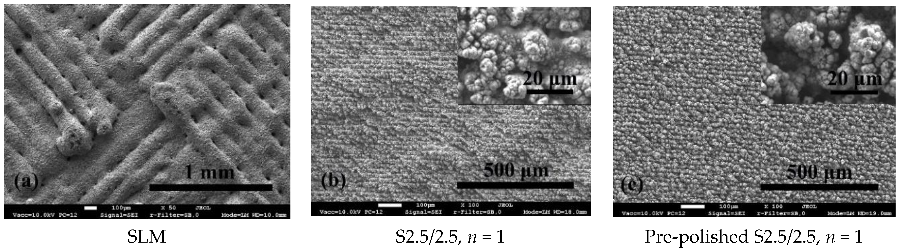
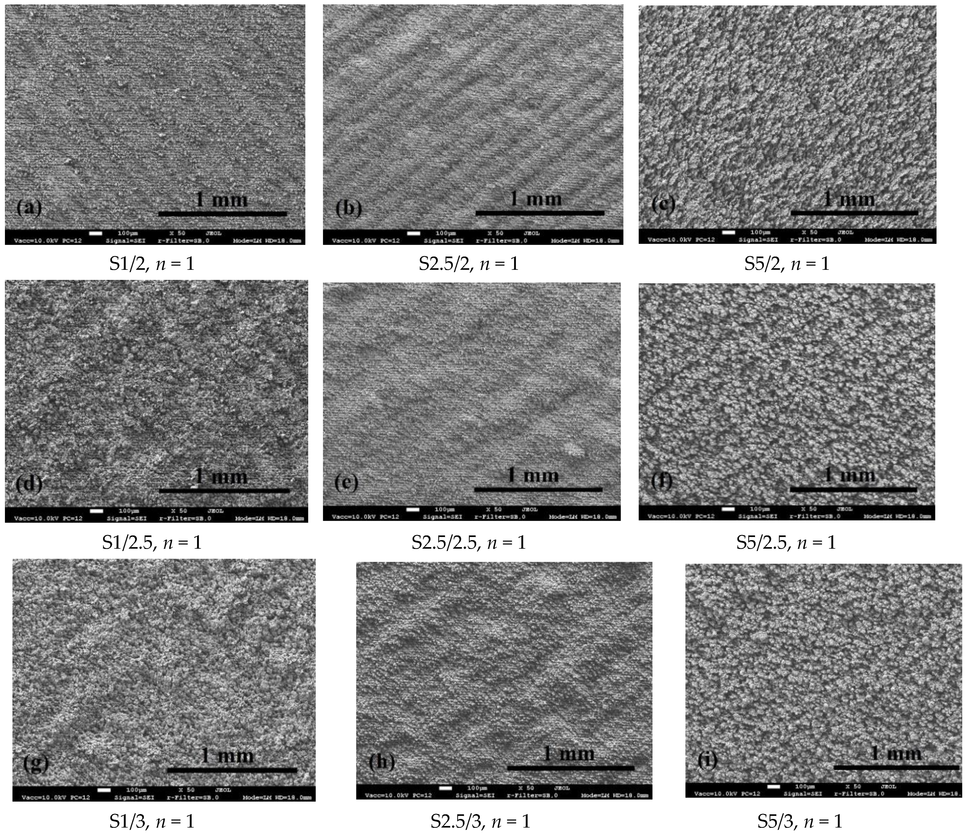
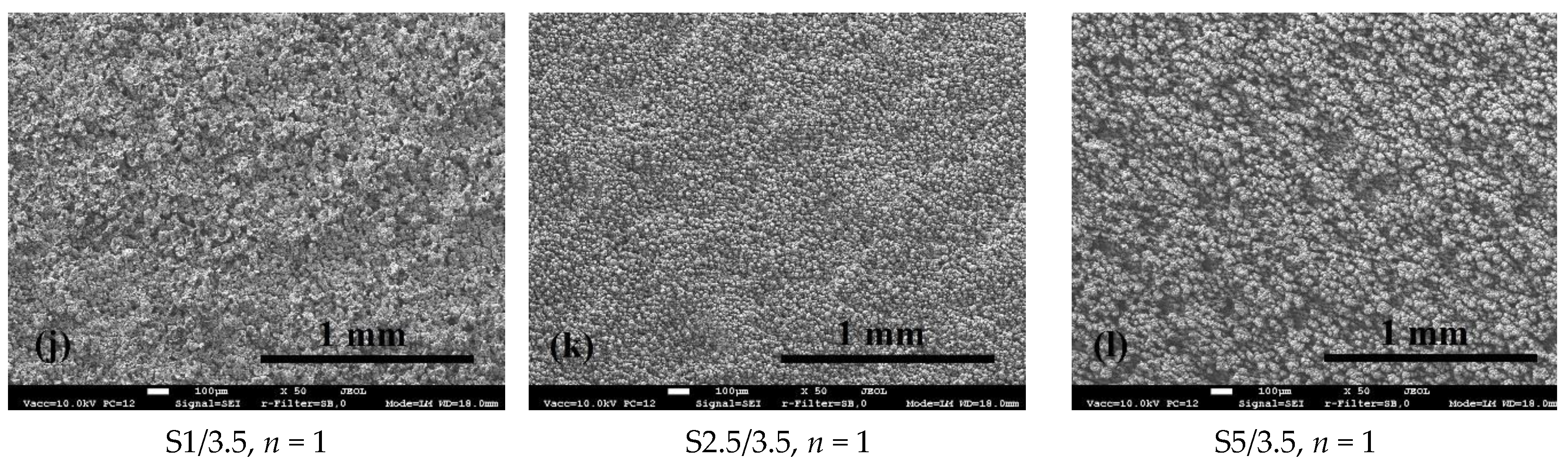
3.1. Surface Morphology

It is known that laser processing creates certain morphology of the surface and the obtained texture depends strongly not only on the parameters of laser beam, but also on the scanning speed and trajectory. One of the simplest and often used processing manner is scanning by line trajectory, arranging the lines in certain density. When the scanning line density is low, the morphology consists of the formed individual μ-channels along with the areas of primary morphology. With the increasing line density, the area of primary morphology decreases, and finally it disappears when scanning is performed with overlapping. Since the surface of as-manufactured SLM is quite rough, in the present research, the laser scanning with overlapping was applied in order, beside each other, to eliminate primary very rough morphology obtained after SLM process. Firstly, the effect of laser processing was tested on the polished (Ra = 0.2 μm) top-surface of SLM specimen. In order to evaluate the effect of repeated laser processing, the one-time processed surface was compared with two- and four-times processed surfaces. Figure 2a,d show the morphology after one time processing at 2.5 W power and 2.5 mm/s scanning speed. Uniform texture with globule-like morphology was obtained. The approximate size of globules was 10–20 μm with gaps between them having the similar width 10 μm.
The analysis of the surface under higher magnification showed that globule-like asperities consist of fine near-spherical formations (Figure 2d). The morphology of surface at micro and submicro levels changed when the surface was laser processed two times (Figure 2b,e). The globule-like asperities became more elongated and oriented and more expressed line scanning tracks were formed (Figure 2b). At the submicroscopic level the morphology seemed to be less porous (Figure 2e); however, the presence of microcracks were established, highly likely induced by a high level of residual tensile stresses [17] (pp. 310–313). When the surface was four times processed, the morphology became more coarse and less uniform (Figure 2c,f): the lateral size of globule-like asperities and gaps between them increased by 3–7 times, as compared with a one-time processed surface.
Figure 3a shows the top-surface morphology of the as-manufactured SLM specimen. The morphology is rough and consists of parallel humps having 100 μm in width and oriented in accordance with the laser scanning sequence during the SLM process. The texture of this surface after laser processing is shown in Figure 3b. The initial morphology was completely eliminated. The texture obtained at the micro- and submicroscopic level did not differ significantly from that obtained on pre-polished surface (Figure 3c). However, slight residual undulation, pre-determined by the initial morphology of SLM surface, was observed.
The morphology of repeatedly processed surface (2 and 4 times) was analyzed as well (Figure 4). Similarly as for pre-polished surface, two-times laser processing has formed less porous texture and visually slightly reduced the residual undulation (Figure 4b). Submicroscopic morphology of globule-like asperities consisting of fine near-spherical formations partially transformed into flower-like formations (Figure 4e). However, the presence of microcracks was established on this surface as well as for the pre-polished surface (Figure 4b). The size of cracks increased significantly after the surface was processed four times (Figure 4c). Maraging steels typically possess high resistance to thermal cracking. The most likely cause of cracks in this case, we consider cracking of oxide phases that do not have as high resistance to cracking as treated steel under the influence of tensile thermal stresses inevitably formed in the surface layers. The absence of cracks after the first treatment can probably be explained by a lower degree of surface oxidation and/or less penetration of oxide phases deep into the surface layers, as a result the subsurface layers of tough steel had a stronger cracks restraining effect. Thus, the obtained results revealed that laser reprocessing of SLM surfaces is not expedient.
Figure 5 shows the morphologies obtained at various laser powers and scanning speeds. It was observed that most fine and uniform morphology is obtained applying 2.5 mm/s scanning speed (Figure 5b,e,h,k). The reduction of the scanning speed results in a formation of less uniform texture (Figure 5a,d,g,j), in which near spherical submicroscopic morphology of globules partially transformed into flower-like structure (Figure 5d). The increase in scanning speed led to a formation of coarser morphology (Figure 5c,f,i,l). At the same time, the variation of laser power has negligible effect on the surface morphology—very similar textures were observed at different powers and constant scanning speed.

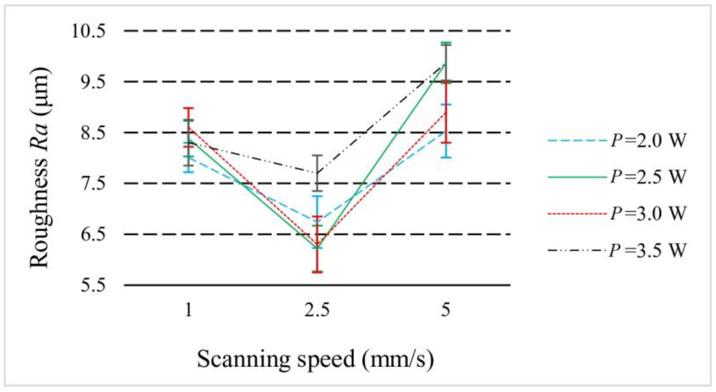
3.2. Surface Roughness

Figure 6 and Figure 7 present the results of roughness measurements. The roughness of the pre-polished surface increased after one-time laser processing (Figure 6). Repeated processing did not influence visibly the Ra parameter while after four-times processing Ra increased 2.7 times, what may be associated with the formation of coarser morphology. In the case of as-manufactured SLM surface processing, the roughness was reduced 3 times applying one-time processing (Figure 6). However, Ra parameter for as-manufactured surface after laser processing was 2 times bigger than that for pre-polished. This can be associated with the presence of residual undulation along with submicro-asperities of the texture. The formation of microcracks and their growth with the increase of processing number led to an increase in surface parameter Ra (Figure 6).
The variation of laser scanning speed and power had influence on the Ra parameter value as well (Figure 7). The least value of Ra parameter was determined on specimen processed at 2.5 W power and 2.5 mm/s speed and showed more uniform and less rough morphology. The reduction and increase in scanning speed led to an increase in the Ra parameter as a result of the formation of less uniform and more coarse textures, respectively. Such tendency was found to be similar for all specimen series processed at constant power. The influence of laser power was not so apparent.

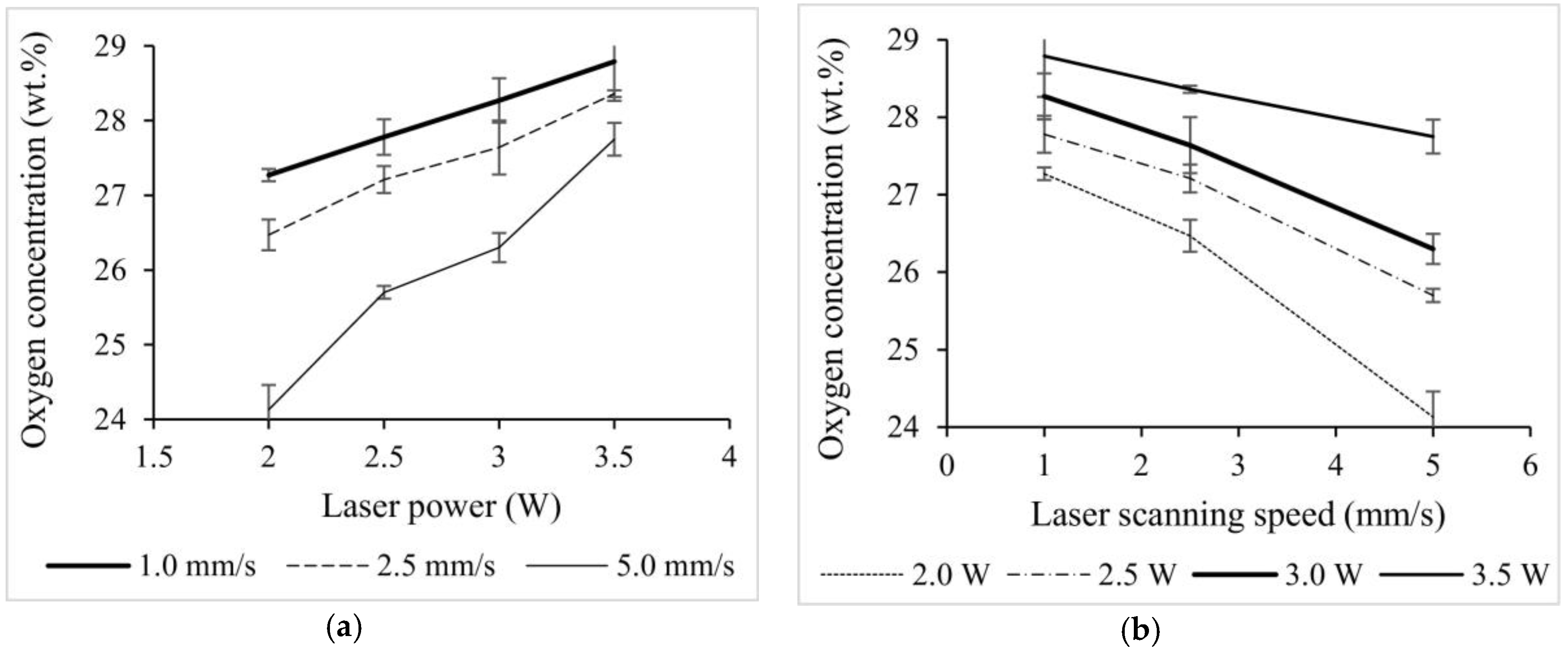
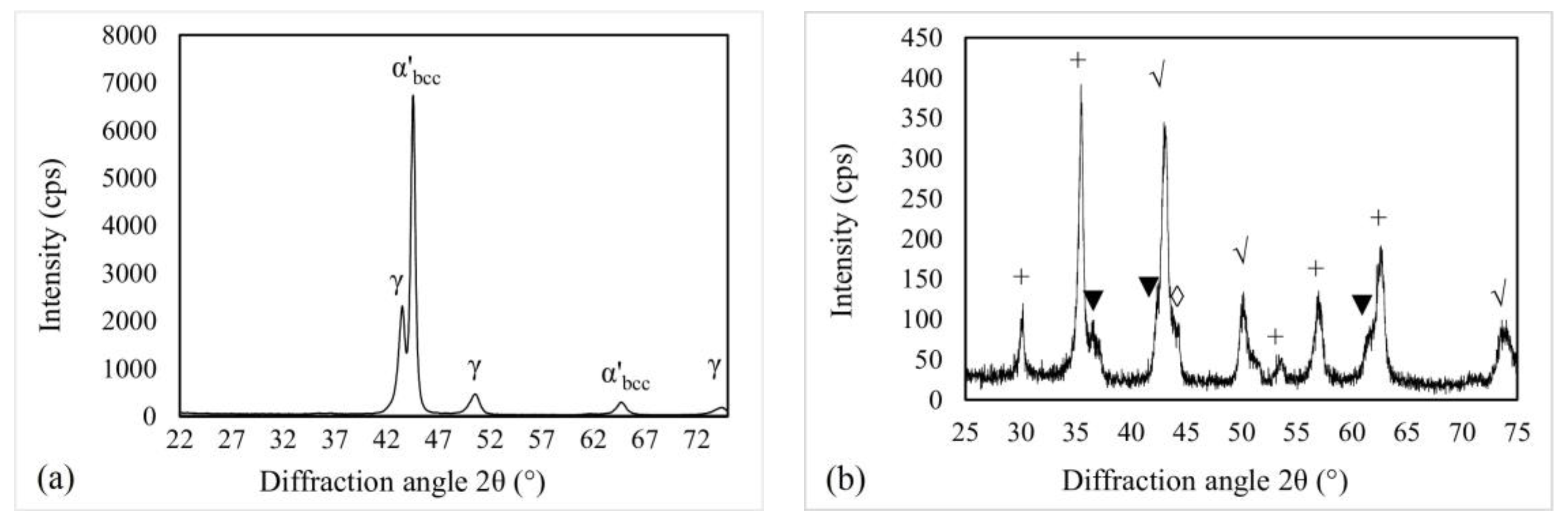
3.3. Surface Elemental and Phase Composition

The results of energy dispersive spectroscopy (EDS) are presented in Table 5 and Figure 8. According to EDS, elemental composition of specimen surface after SLM did not differ significantly from that of the initial powder. After laser processing in air, oxygen concentration at the surface increased visibly and ranged between 24.1 wt.% and 28.8 wt.% (Table 5), indicating that intensive surface oxidation took place during the processing. It was determined also, that the oxygen amount at the surface tends to rise with the increase of the laser power (Figure 8a) and reduction of the laser scanning speed (Figure 8b). Thus, the highest average oxygen concentration of 28.8 wt.% was reached at 3.5 W laser power and 1 mm/s scanning speed. At the same time, the higher the oxygen concentration, the less the difference for different samples. This can be explained by the approaching to the some possible maximum in oxygen concentration.
Figure 9 shows the typical XRD patterns of the as-manufactured SLM specimen surface and specimen surface after laser processing. The major peaks appeared in the XRD pattern of the SLM sample are attributable to the bcc-lattice Fe with parameter a = 2.866 Å (Figure 9a). This phase can be identified as cubic martensite, which is typical for maraging steels. Less intensive reflections belong to residual austenite (fcc-lattice; a = 3.63 Å). X-ray diffraction pattern obtained on surface, laser-processed in oxidizing atmosphere at 2.5 mm/s scanning speed and 3.5 W laser power (S2.5/3.5), revealed the presence of various oxides. The major reflections appeared on the pattern can be attributed to iron cobalt oxide (Fe2CoO4) and titanium cobalt oxide (Ti0.11Co0.89O0.99; Figure 9b). The similar set of the reflections was observed for all the surfaces under analysis. According to the results of Rietveld analysis, the total amount of oxides changed with variation of laser scanning speed: the less scanning speed the higher amount of oxides, what is related to a longer heating duration, slower cooling rate and, as a result, to a longer surface interaction with oxygen at high temperature (Figure 10).

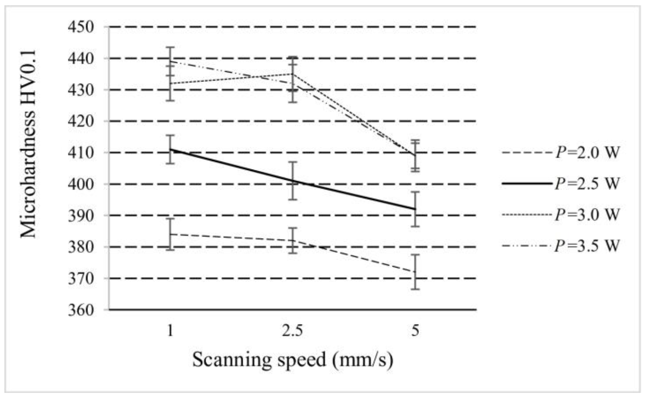
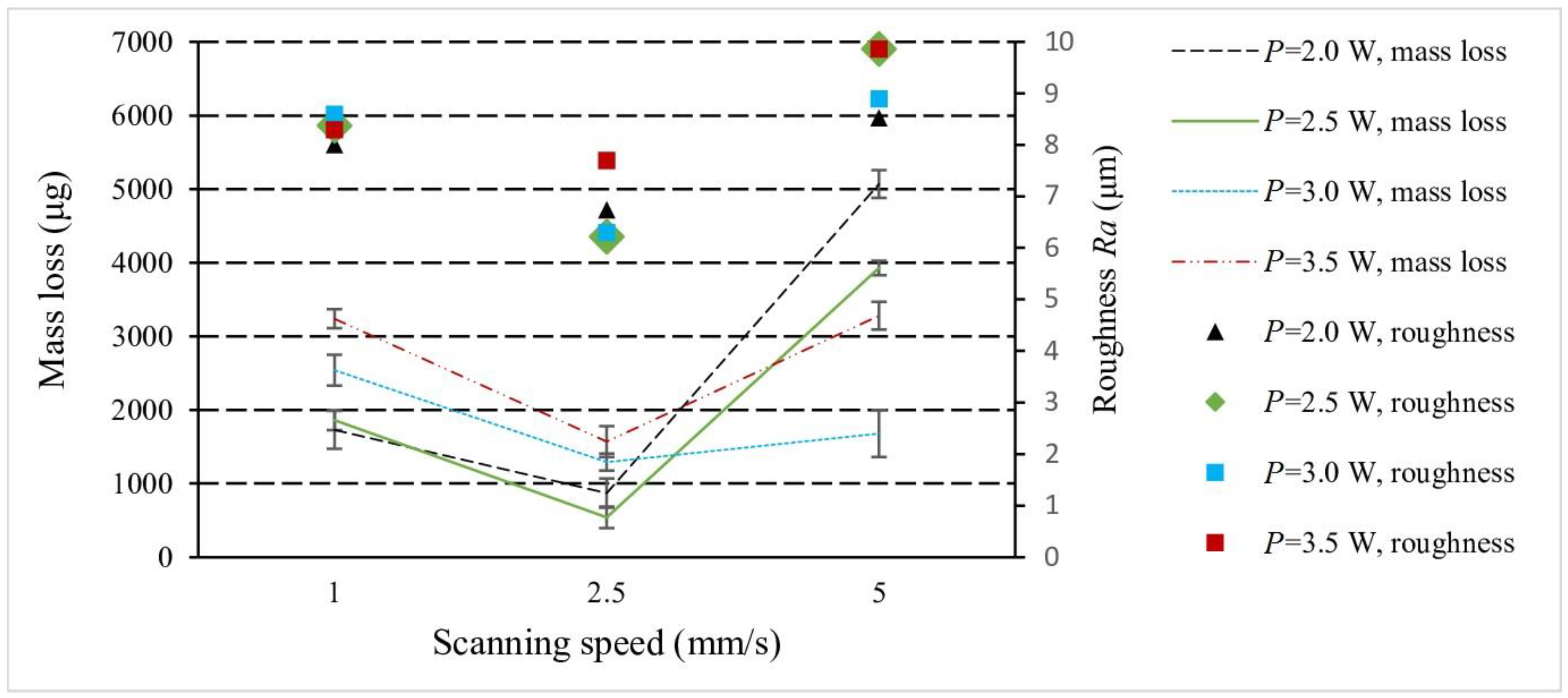
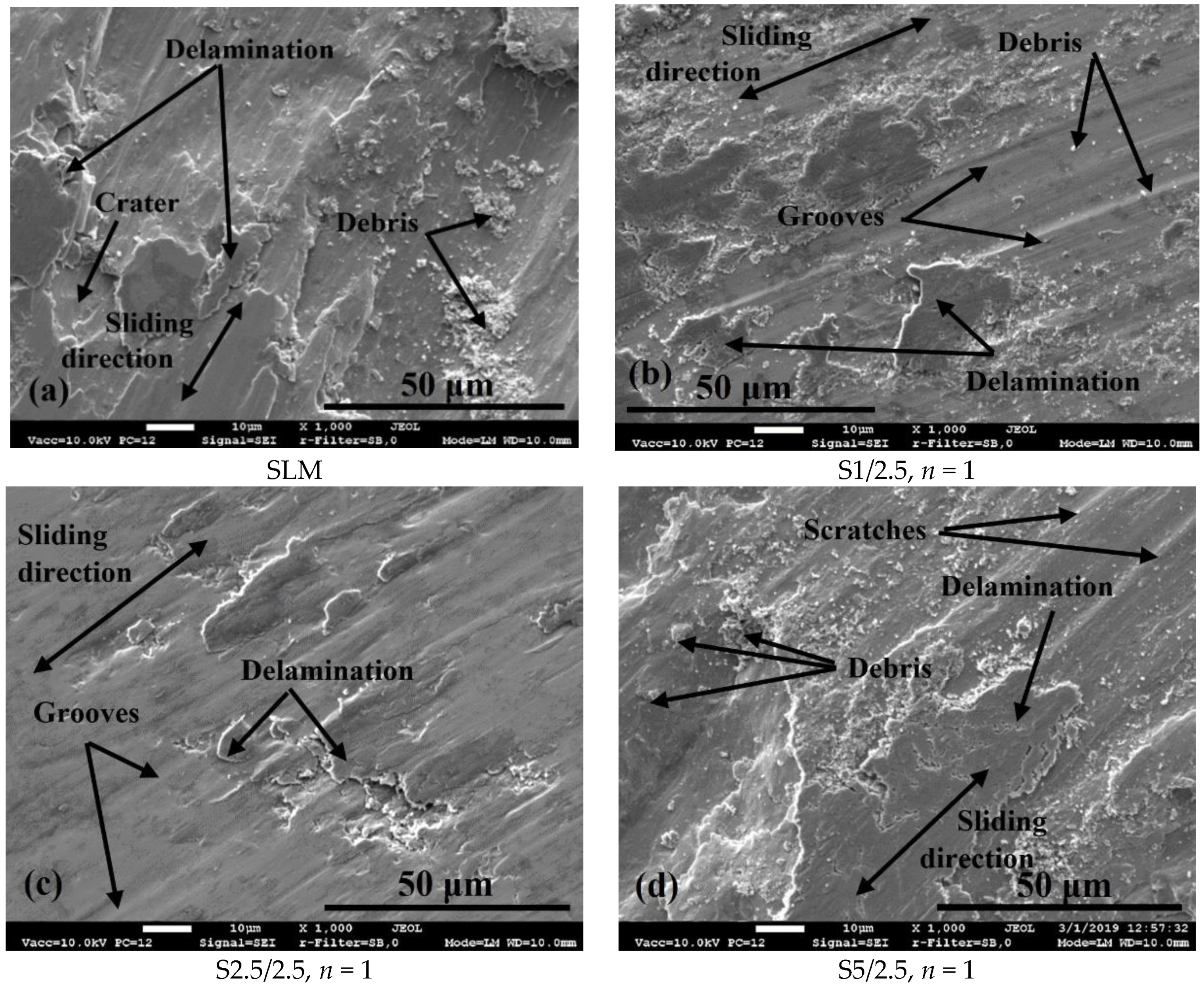
3.4. Surface Microhardness and Tribology

The microhardness of SLM surface was 297 HV. As was expected, microhardness increased significantly after laser processing (Figure 11). The average hardness values for laser-processed surfaces ranged from 392 to 411 HV. The microhardness increase trend with the decrease in scanning speed was observed clearly. These results were found to be in good correlation with oxides concentration at surface, allowing one to assume that the increased surface microhardness is largely predetermined by the formation of oxides. In general, laser processing allowed a hardness increase from 32% to 38% and provided improvement of surface wear resistance (Figure 12).
The mass loss during two-body dry sliding wear test of laser processed specimens were between 540 and 3930 μg, i.e., 2.3–16.8 times less as compared with SLM specimen (9070 μg). According to the Reye–Archard–Khrushchov law [34,35], the wear rate is reversely proportional to the hardness. It is also well known that wear rate tends to be increased along rise in roughness, since the specific load increases due to reduced real contact area [36]. Clear correlation between surface roughness and mass loss results (see Figure 12) obtained in present work testifies that the texture, formed by laser processing, has significant impact on wear rate.
The worn surface of the SLM specimen after the two-body dry sliding test is shown in Figure 13a. Wide scratches, surface layer fragmentation and coarse craters formed due to delamination of surface fragments indicate the domination of delamination and abrasive wear processes. The signs of delamination wear mechanism were observed on worn tracks of laser-processed surfaces as well (Figure 13b–d). However, in the case of 1 mm/s scanning speed, the delaminated fragments were much thinner and no deep coarse craters were found (Figure 13b), what is consistent with much less wear rate, as compared with the as-manufactured SLM surface. It may be associated with quite uniform micromorphology on the one hand and the presence of a high amount of oxides, which are typically quite brittle, on the other. The surface seemed more flat with the presence of shallow grooves, highly likely, due to plastic deformation. On the surface processed with 2.5 mm/s scanning speed, only occasional areas of delamination were observed along with shallow grooves (Figure 13c). The surface seemed mostly plastically deformed, explaining why the mass loss of this surface was the lowest and indicating that the parameters of laser processing applied for this surface formed optimal combination of oxide concentration, amount of plastic γFe-based phase and texture. In the case of 5 mm/s speed, worn surface seemed similar to worn SLM surface: coarse delaminated fragments, a lot of debris, big craters—a result of coarse less uniform texture (Figure 13d).

4. Conclusions

In the present work, pulsed laser processing under the ablation mode in air was applied for the surface modification of the maraging steel SLM part. Several conclusions may be drawn based on the results of the analyses.
Pulsed laser processing at the ablation mode in air atmosphere allow obtaining a uniform modified micro-textured surface directly on the SLM part without surface pre-polishing. The surfaces exhibited negligible residual undulation predetermined by the initial surface morphology of the SLM part after manufacturing and the Ra parameter much less as compared with the SLM as-manufactured surface (Ra = 17.9 μm). Applying the denoted parameters of laser processing, obtained Ra values ranged between 6.22 and 9.87 μm. The least roughness was obtained at the 2.5 W laser power and 2.5 mm/s scanning speed.
The intensive oxidation of the surface during laser processing results in a formation of significant oxides (such as the Fe2CoO4 and Ti0.11Co0.89O0.99) amount, which can be controlled by scanning speed and/or laser power. The oxide phase presence at the surface provides an improvement in hardness and wear resistance. However, a surface roughness, determined by the obtained morphology, is the dominating factor for wear rate and the lowest mass loss was determined for the specimen with the lowest Ra parameter, obtained at 2.5 W laser power and 2.5 mm/s scanning speed.
The repeated laser processing induced the cracking of the surface layers due to the overheating and is not expedient.
The further study, making focus on the optimization of laser processing parameters, could contribute to the development of the surface laser processing technologies for maraging steels SLM parts.

Author Contributions

Conceptualization, O.Č. and J.Š.; methodology, N.V.; formal analysis, V.M. and S.I.; investigation, O.Č. and J.Š.; resources, V.M. writing—original draft preparation, J.Š.; writing—review and editing, J.Š. and O.Č.; supervision, O.Č. All authors have read and agreed to the published version of the manuscript.

Funding

This research received no external funding.

Conflicts of Interest

The authors declare no conflict of interest.

References

  1. Eyers, D.R.; Potter, A.T. Industrial additive manufacturing: A manufacturing systems perspective. Comput. Ind. 2017, 92–93, 208–218. [Google Scholar] [CrossRef]
  2. Bhavar, V.; Kattire, P.; Patil, V.; Khot, S.; Gujar, K.; Singh, R. A review on powder bed fusion technology of metal additive manufacturing. In Proceedings of the 4th International Conference and Exhibition on Additive Manufacturing Technologies AM-2014, Bangalore, India, 1–2 September 2014; pp. 1–7. [Google Scholar]
  3. Deckard, C. Method and Apparatus for Producing Parts by Selective Sintering. U.S. Patent US4863538, 17 October 1986. [Google Scholar]
  4. ASM International. Maraging steels. In ASM Handbook, Volume 1: Properties and Selection: Irons, Steels, and High-Performance Alloys, 10th ed.; ASM International: Materials Park, OH, USA, 1990; Volume 1, pp. 1869–1887. [Google Scholar]
  5. 18 Per Cent Maraging Steels. Engineering Properties. INCO Databooks. 1976. Available online: https://www.nickelinstitute.org/media/1598/18_nickelmaragingsteel_engineeringproperties_4419_.pdf (accessed on 29 May 2020).
  6. Hall, A.M. The Metallurgy, Behavior, and Application of the 18-Percent Nickel Maraging Steels. A Survey; Technology Utilization Division, Office of Technology Utilization, National Aeronautics and Space Admin: Washington, DC, USA, 1968; p. 143. [Google Scholar]
  7. Klocke, F.; Arntz, K.; Teli, M.; Winands, K.; Wegener, M.; Oliari, S. State-of-the-art laser additive manufacturing for hot-work tool steels. Procedia CIRP 2017, 63, 58–63. [Google Scholar] [CrossRef]
  8. Popov, V.; Fleisher, A. Hybrid additive manufacturing of steels and alloys. Manuf. Rev. 2020, 7, 6. [Google Scholar] [CrossRef] [Green Version]
  9. Ebrahimi, A.; Mohammadi, M. Numerical tools to investigate mechanical and fatigue properties of additively manufactured MS1-H13 hybrid steels. Addit. Manuf. 2018, 23, 381–393. [Google Scholar] [CrossRef]
  10. Decker, R.F.; Eash, J.T.; Goldman, A.J. Eighteen percent nickel maraging steel. Trans. ASM 1962, 55, 58–76. [Google Scholar]
  11. Azizi, H.; Ghiaasiaan, R.; Prager, R.; Ghoncheh, M.H.; Samk, K.A.; Lausic, A.; Byleveld, W.; Phillion, A.B. Metallurgical and mechanical assessment of hybrid additively-manufactured maraging tool steels via selective laser melting. Addit. Manuf. 2019, 27, 389–397. [Google Scholar] [CrossRef]
  12. Seabrook, J.B. Working with maraging steels-nitriding. Met. Progr. 1963, 84, 78–80. [Google Scholar]
  13. Haynes, A.G. Maraging steels-surface protection and surface effects. In Metallurgical Developments in High Alloy Steels; Special report 86; The Iron and Steel Institute: London, UK, 1964; pp. 125–133. [Google Scholar]
  14. Imrie, W.M. Assessment of maraging steel for aircraft applications. J. R. Aeronaut. Soc. 1966, 70, 776–777. [Google Scholar] [CrossRef]
  15. Graae, A. How to nitride maraging steels. Met. Prog. 1967, 92, 74–76. [Google Scholar]
  16. Tsyrlin, E.S. Nitriding of maraging steel N18K9M5T. Met. Sci. Heat Treat. 1971, 4, 22–25. [Google Scholar] [CrossRef]
  17. Steen, W.; Mazumder, J. Laser Material Processing, 4th ed.; Springer-Verlag: London, UK, 2010; p. 558. [Google Scholar]
  18. Lamikiz, A.; Sánchez, J.A.; López de Lacalle, L.N.; Arana, J.L. Laser polishing of parts built up by selective laser sintering. Int. J. Mach. Tool. Manuf. 2007, 47, 2040–2050. [Google Scholar] [CrossRef]
  19. Bhaduri, D.; Penchev, P.; Batal, A.; Dimov, S.; Soo, S.L.; Sten, S.; Harrisson, U.; Zhang, Z.; Dong, H. Laser polishing of 3D printed mesoscale components. Appl. Surf. Sci. 2017, 405, 29–46. [Google Scholar] [CrossRef]
  20. Yung, K.C.; Wang, W.J.; Xiao, T.Y.; Choy, H.S.; Mo, X.Y.; Zhang, S.S.; Cai, Z.X. Laser polishing of additive manufactured CoCr components for controlling their wettability characteristics. Surf. Coat. Technol. 2018, 351, 89–98. [Google Scholar] [CrossRef]
  21. Ma, C.P.; Guan, Y.C.; Zhou, W. Laser polishing of additive manufactured Ti alloys. Opt. Lasers Eng. 2017, 93, 171–177. [Google Scholar] [CrossRef]
  22. Zhihao, F.; Libin, L.; Longfei, C.; Yingchun, G. Laser polishing of additive manufactured superalloy. Procedia CIRP 2018, 71, 150–154. [Google Scholar] [CrossRef]
  23. Li, Y.-H.; Wang, B.; Ma, C.-P.; Fang, Z.-H.; Chen, L.-F.; Guan, Y.-C.; Yang, S.-F. Material characterization, thermal analysis, and mechanical performance of a laser-polished Ti alloy prepared by selective laser melting. Metals 2019, 9, 112. [Google Scholar] [CrossRef] [Green Version]
  24. Afkhami, S.; Dabiri, M.; Alavi, S.H.; Björk, T.; Salminen, A. Fatigue characteristics of steels manufactured by selective laser melting. Int. J. Fatigue 2019, 122, 72–83. [Google Scholar] [CrossRef]
  25. Nanai, L.; Vajtai, R.; George, T.G. Laser-induced oxidation of metals: State of the art. Thin Solid Films 1997, 298, 160–164. [Google Scholar] [CrossRef]
  26. Schaaf, P. Laser nitriding of metals. Prog. Mater. Sci. 2002, 47, 1–161. [Google Scholar] [CrossRef]
  27. Černašėjus, O.; Škamat, J.; Markovič, V.; Višniakos, N.; Indrišiūnas, S. Surface laser processing of additive manufactured 1.2709 steel parts: Preliminary study. Adv. Mater. Sci. Eng. 2019, 9. [Google Scholar] [CrossRef] [Green Version]
  28. Parfenov, V.A. Laser Micromachnining of Materials: Textbook; Publishing House of the Saint Petersburg Electrotechnical University ETU: Saint Petersburg, Russia, 2011. [Google Scholar]
  29. Yan, J.; Zhou, Y.; Gu, R.; Zhang, X.; Quach, W.-M.; Yan, M.A. Comprehensive study of steel powders (316L, H13, P20 and 18Ni300) for their selective laser melting additive manufacturing. Metals 2019, 9, 86. [Google Scholar] [CrossRef] [Green Version]
  30. Maraging 300 Alloy Steel (UNS K93120). Available online: https://www.azom.com/article.aspx?ArticleID=6751 (accessed on 19 May 2020).
  31. Gursel, A.; Akca, E. 3D surface morphology and roughness on treated surface of Ti–6Al–4V alloy by Nd:YAG laser: Effect of spot size. In Proceedings of the 5th International Conference on Welding Technologies and Exhibition (ICWET’18), Sarajevo, Bosnia and Herzegovina, 26–28 September 2018; pp. 324–335. [Google Scholar]
  32. Tzeng, Y.F. Process characterisation of pulsed Nd:YAG laser seam welding. Int. J. Adv. Manuf. Tech. 2000, 16, 10–18. [Google Scholar] [CrossRef]
  33. Naeem, K. Developments in laser microwelding technology. In Handbook of Laser Welding Technologies, 1st ed.; Katayama, S., Ed.; Woodhead Publishing Limited: Cambridge, UK, 2013; pp. 163–212. [Google Scholar]
  34. Reye, T. Zur theorie der zapfenreibung. Der Civil. 1860, 6, 235–255. [Google Scholar]
  35. Popov, V.L. Contact Mechanics and Friction. Physical Principles and Applications; Springer: Berlin, Germany, 2010; p. 22. [Google Scholar]
  36. Bayer, R.G.; Sirico, J.L. The influence of surface roughness on wear. Wear 1975, 35, 251–260. [Google Scholar] [CrossRef]
Figure 1. SEM micrograph of morphology of the powder for selective laser melting (SLM).
Coatings 10 00600 g001
Figure 2. SEM micrographs of textures obtained on pre-polished SLM part surface: (a,d) texture of the onetime processed surface; (b,e) texture of the two times processed surface and (c,f) texture of the four times processed surface.
Coatings 10 00600 g002
Figure 3. SEM micrographs of surface morphology of as-manufactured SLM specimen (a: top surface) and textures obtained with laser processing on as-manufactured (b) and pre-polished SLM surface SLM top surface (c).
Coatings 10 00600 g003
Figure 4. SEM micrographs of textures obtained on as-manufactured SLM part top surface: (a,d) texture of the one time processed surface; (b,e) texture of the two times processed surface and (c,f) texture of the four times processed surface.
Coatings 10 00600 g004
Figure 5. SEM micrographs of morphology of as-manufactured SLM part top surface one time processed with different laser scanning speed and power: (a) S1/2; (b) S2.5/2; (c) S5/2; (d) S1/2.5; (e) S2.5/2.5; (f) S5/2.5; (g) S1/3; (h) S2.5/3; (i) S5/3; (j) S1/3.5; (k) S2.5/3.5; (l) S5/3.5 specimen.
Coatings 10 00600 g005aCoatings 10 00600 g005b
Figure 6. Roughness Ra of the pre-polished and as-manufactured SLM surfaces after laser processing for one, two and four time at 2.5 mm/s laser scanning speed and 2.5 W laser power.
Coatings 10 00600 g006
Figure 7. Roughness Ra of the surfaces one time laser-processed at different scanning speeds and powers.
Coatings 10 00600 g007
Figure 8. Effect of laser power (a) and laser scanning speed (b) on the oxygen concentration at the laser-processed surfaces.
Coatings 10 00600 g008
Figure 9. XRD patterns of pre-polished as-manufactured SLM specimen (a) and laser processed specimen S2.5/3.5 (b): α’bcc—cubic martensite; γ—austenite; +—Fe2CoO4; ▼—Ti0.11Co0.89O0.99; √—Mo0.27Ni0.73 and/or γ-Fe; ◊—Mo0.03 Ni0.97 and/or Fe0.5Ni0.5.
Coatings 10 00600 g009
Figure 10. Oxides concentration at the surfaces laser-processed with different scanning speed and constant power P = 2.5 W.
Coatings 10 00600 g010
Figure 11. Hardness of specimens laser-processed at different laser scanning speeds and powers.
Coatings 10 00600 g011
Figure 12. Mass loss under two body sliding wear and roughness of specimens laser-processed with different laser scanning speeds and powers.
Coatings 10 00600 g012
Figure 13. SEM micrographs of morphology of the worn surfaces of: (a) as-manufactured SLM specimen; (b) S1/2.5 specimen; (c) S2.5/2.5 specimen; (d) S5/2.5 specimen.
Coatings 10 00600 g013
Table 1. Characteristics of SLM laser and process parameters.
LaserThickness of Layer, mmLaser Operating Rate, mm/sShielding Gas
Wave Length, nmPower, WSpot Size, mmType Consumption, l/h
1064100Ø 0.20.030.2Ar0.75
Table 2. Coding of the processed samples.
Laser Scanning Speed v, mm/sLaser Power, W
22.533.5
1S1/2S1/2.5S1/3S1/3.5
2.5S2.5/2S2.5/2.5S2.5/3S2.5/3.5
5S5/2S5/2.5S5/3S5/3.5
Table 3. Energy characteristics of laser processing (at f = 10 kHz, d = 25 μm).
Energy Parameters of the ProcessAverage Laser Power, W
2.02.53.03.5
Ep, J2.0 × 10−42.5 × 10−43.0 × 10−43.5 × 10⁻⁴
Pp, W2.0 × 1042.5 × 1043.0 × 1043.5 × 104
Pd, W∙m−24.07 × 10135.10 × 10136.11 × 10327.13 × 1013
Table 4. Overlap coefficients.
Laser Processing Speed, mm∙s−112.55
Overlap coefficient, %99.6099.0098.00
Table 5. Elemental composition of initial steel powder and samples surfaces (in wt.%, by energy dispersive spectroscopy (EDS)).
SpecimenElement
FeNiCoMoTiO
Initial powderBalance20.06.94.50.72.0
SLM specimen23.08.24.10.75.1
S5/2 (v = 5 mm/s/P = 2.0 W)15.311.03.71.224.1
S1/3.5 (v = 1 mm/s/P = 3.5 W)11.98.83.31.328.8

