Article

Microstructure and Properties of Cr-Fe2B Composite Coatings Prepared by Pack-Preboronizing Combined with Electro Brush-Plating

1
College of Material Science and Engineering, Chongqing University of Technology, Chongqing 400054, China
2
Chongqing Municipal Key Laboratory of Institutions of Higher Education for Mould Technology, Chongqing University of Technology, Chongqing 400054, China
3
College of Mechanical Engineering, Chongqing University of Technology, Chongqing 400054, China
4
School of Materials and Energy, Southwest University, Chongqing 400715, China
*
Authors to whom correspondence should be addressed.
Coatings 2020, 10(6), 519; https://doi.org/10.3390/coatings10060519
Submission received: 6 May 2020 / Revised: 23 May 2020 / Accepted: 26 May 2020 / Published: 28 May 2020
(This article belongs to the Special Issue Surface Engineering for Friction and Wear Reduction)

Abstract

:
Cr-Fe2B composite coatings were prepared on carbon steels by pack-boronizing followed by electro brush-plating. The microstructure and properties of the coatings annealed at different temperatures were studied. The coatings show a gradient structure composed of a Cr-layer and a Fe2B-layer and have excellent thermal stability, and no new layers and/or transition layers are formed in the coating during annealing up to 1000 °C. The Cr-layer has an amorphous structure and is transformed into nanosized grains when the annealing temperature increases to 700 °C. As the annealing temperature is further increased, the nanograins grow rapidly. The microcracks in the Cr-layer increase sharply after annealing at 550 °C and then decrease significantly with any further increase of the annealing temperature. The pre-deposited Fe2B-layer prevents the formation of carbon-poor zones in the steel substrate during annealing. It is considered that high-temperature (>700 °C) annealing helps to eliminate coating defects, increase the coating density and obtain better wear resistance and corrosion resistance. Surprisingly, the as-plated and low temperature annealed samples also show good wear resistance and corrosion resistance, which may be related to their amorphous structure and nanocrystalline structure.

1. Introduction

As an important part of power transmission and speed regulation, the performance of the entire equipment is affected by gears [1,2,3]. When a gear is used in a complex environment such as high speed, high temperature, and/or high corrosion, the gear surface is required to have multiple functional characteristics such as high hardness, good wear resistance and good corrosion resistance. Conventional methods such as carburizing, nitriding or surface hardening cannot produce this kind of multifunctional gear. In order to strengthen service ability, many new surface modification techniques, such as large current pulsed electron beam [4,5], physical or chemical vapor deposition (PVD and CVD) [6,7], plasma-transferred arc welding [8], laser surface modification [9,10,11,12], shot peening [13,14], magnetron sputtering [15], plasma sprayed [16], and rapid solidification technique [17], have been adopted to improve material surface properties.
Brush-plating technology is a rapid and effective surface modification technology to enhance or repair the surface of mechanical parts [18]. This technology plays an important role in the field of remanufacturing and has many unique advantages, such as flexible operation, low energy consumption, strong applicability and no need for a plating bath [19,20]. The coating deposited by brush-plating has unique corrosion resistance, abrasion resistance and hardness advantages [21,22,23]. The brush-plating has been applied in many fields such as the study of superhydrophobic surfaces [24,25]. It has been pointed out that like electroless or electroplated palladium films, it is possible to deposit stainless steel palladium films with good corrosion resistance and adhesion strength by brush-plating [26]. Zhong et al. [27] claimed that the brush-plated nickel-tungsten alloy coating has a good friction coefficient and corrosion resistance after annealing treatment. Hu et al. [8] found that the Cr-coating deposited by brush-plating has high hardness and good wear resistance after annealing.
In our previous research, it was found that when annealing the brush-plated Cr-coating on the carbon steel, carbon-poor zone will appear in the sub-surface of the steel substrate, which will degrade the comprehensive performance of the Cr-coating [8]. In this study, a Fe2B-layer was pre-deposited on the carbon steel as the middle layer, and the brush-plated Cr-layer was deposited as the outermost layer. The changes in microstructure and properties were studied as the annealing temperature increased.

2. Experimental

2.1. Materials and Methods

Commercial AISI 5140 steel with a composition of Fe-0.40C-0.23Si-0.7Mn-0.8Cr-0.03Ni (wt.%) was selected as the raw material for the experiment. The raw material was cut into cuboid specimens with dimensions of 25 mm × 20 mm × 6 mm. Firstly, a Fe2B-coating was prepared on the specimens by pack-boronizing. For the pack-boronizing, the samples were ground and polished and then packaged in a ceramic can filled with packed powders mingled by FeB (50 wt.%) as the feedstock, KBF4 (5 wt.%) as the activator, La2O3 (5 wt.%) as the modifier and Al2O3 (40 wt.%) as the inert filler. All powders have a particle size of less than 75 microns. Then, the ceramic can was heated in a box-type furnace at 950 °C for 3 h and then naturally cooled in a furnace. Secondly, electro brush-plating (MBPK-50A Wuhan Research Institute of Materials Protection, Wuhan, China) was employed to deposit a Cr-coating on the surface of the preboronized samples. Prior to brush-plating, the preboronized samples were cleaned and slightly polished on 800-grit SiC paper. Brush-plating was performed at room temperature. The treatment procedures and parameters are as follows: electrical cleaning (+12 V, 60 s), strong activation (−10 V, 60 s), weak activation (−12 V, 30 s), and final plating (+10 V, 10 min). After brush-plating, the samples were washed with a large amount of water and alcohol. Then, the as-plated samples were placed into a box-type furnace annealing treatment for 20 min at 550, 700, 850, and 1000 °C (denoted as A550, A700, A850, and A1000 respectively). After annealing, all samples were naturally cooled to room temperature in the furnace.

2.2. Characterization

Backscattered electron imaging (BSEI), secondary electron imaging (SEI) and energy dispersive spectrometry (EDS, AZtech Max2, Oxford Instruments, London, UK) installed in a field emission gun scanning electron microscope (FEG-SEM, Zeiss Sigma HD, Zeiss, Dresden, Germany) were applied to characterized the microstructure. Prior to microstructure examinations, the samples were mechanically polished down to a 3000-grit SiC paper and then electropolished with an electrolyte of perchloric acid (10%) and ethanol (90%) at 30 V and −30 °C. The Vickers hardness test was performed on a microhardness tester (HVS-1000, Shanghai CSOIF Co., Ltd., Shanghai, China) with a load of 200 g and a loading time of 10 s. Each hardness value is an average of at least 5 indentations at the same depth from the sample surface. Friction and wear tests were carried out on a reciprocating tribometer (UMT TriboLab, Bruker, Billerica, MA, USA), with a 6 mm steel balls (AISI 52100) as friction pairs. The parameters were as follows: load 8 N, duration time 20 min, frequency 5 Hz, and wear scar length 10 mm. For each state of the sample, at least three friction and wear experiments were done to verify the repeatability of the experimental results. The potential dynamic polarization curves were measured by a Reference 3000 instrument (Gamry, Warminster, PA, USA) in 3.5% NaCl solution, and the corrosion behavior of annealed samples and matrix was evaluated. The dynamic potential range was −1 to 2 V, and the scanning speed was 2 mV/s.

3. Results and Discussions

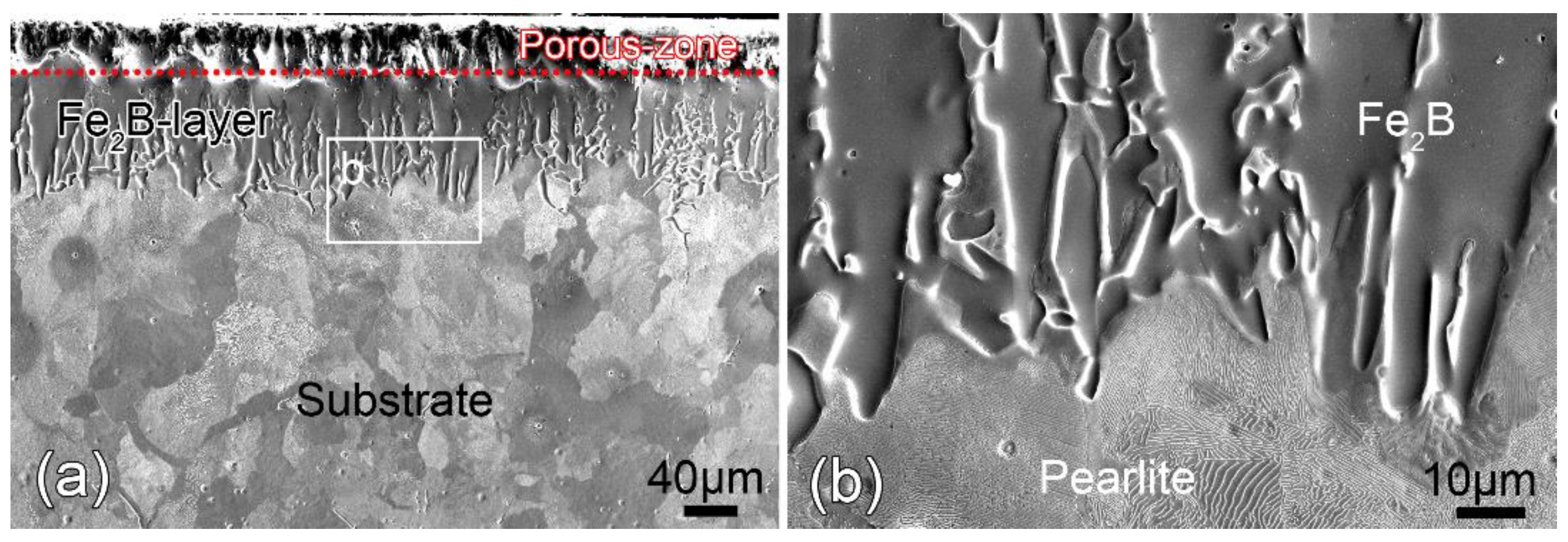
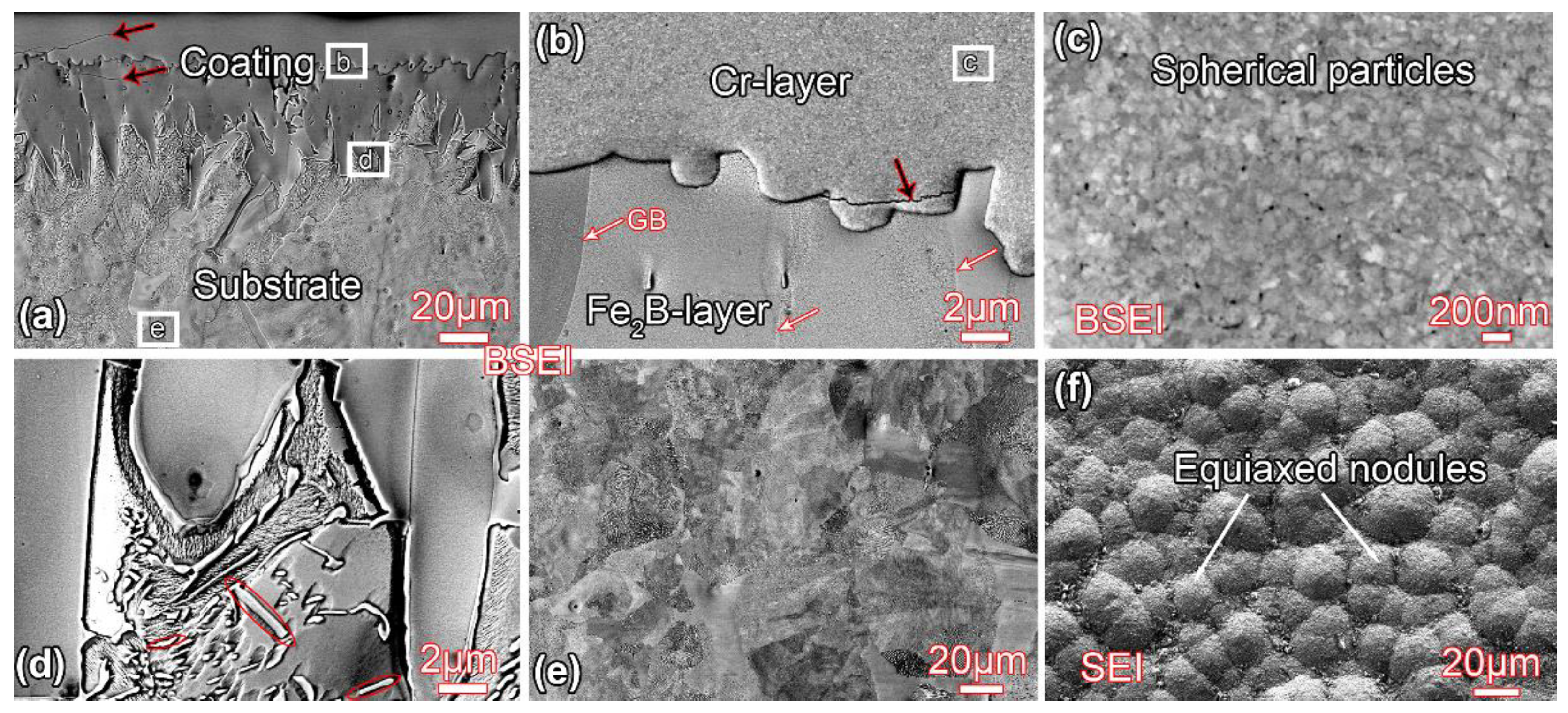
3.1. Microstructure before Annealing

Figure 1 shows the microstructure observed from the cross-sectional view of the sample after pack-preboronizing treatment. As can be seen from Figure 1a, a saw-toothed coating is clearly visible, which is reported as the typical morphology of the Fe2B-coating [28]. Each saw tooth is actually a columnar grain of Fe2B, as shown in Figure 1b. The average thickness of the Fe2B-coating is measured as about 110 μm according to the measurement method in [28]. However, there is a porous-zone layer containing a lot of pores and cracks in the outermost layer of the Fe2B-coating. The porous-zone layer is relatively loose and poor in density, which may reduce the interfacial adhesion to the subsequent plated Cr layer. Therefore, prior to brush-plating treatment, the porous-zone layer was ground away with SiC paper. After grounding, the thickness of the Fe2B-coating is reduced to about 75 µm. Additionally, the substrate has a typical hypoeutectoid steel structure consisting of a mixture of ferrite grains and pearlite colonies, as shown in Figure 1b.
Figure 2 shows the microstructure of the sample after brush-plating treatment. A gradient coating can be clearly identified from the cross-sectional view, as shown in Figure 2a. The high-magnification BSEI image (Figure 2b) shows that the gradient coating consists of two parts from outside to inside: Cr-layer and Fe2B-layer. The average thickness of the Cr-layer is determined as approximately 18 µm. A highly-magnified image shows that the Cr-layer consists of equiaxed nodules rather than grains (Figure 2c,f). The average diameter of the equiaxed nodules is measured as 16 μm. It has been reported that the nodule size is depended on the continuous supply of solution, appropriate contact pressure, and the movement speed of the anode of the brush-plating processing [29]. Additionally, as shown by the black arrows in Figure 2a,b, micro-cracks are clearly observed within the Cr-layer. It has been pointed out that the generation of micro-cracks in the brush-plated coatings is closely related to hydrogen emission and internal residual stress during the electro brush-plating deposition [8,18,30]. Obviously, the presence of micro-cracks will weaken the adhesion between Cr-layer and Fe2B-layer, deteriorating the properties of the coating [8]. After brush-plating, the morphology and thickness of the Fe2B-layer do not change.
Generally, FeB phase may form during the boronization process, and it is easy to distinguish the FeB phase from the Fe2B phase in the SEM images [31,32,33,34,35]. However, after carefully examining the microstructure of the coating, no FeB was found in this study. According to the Fe-B equilibrium diagram, both FeB and Fe2B can be formed during cooling. It has been pointed out that FeB (boron-rich phase) is formed on the surface, while Fe2B (iron-rich phase) is located on the subsurface layer and adjacent to the steel substrate material because of the boron concentration decreases from the surface towards the interior [32]. In this study, prior to brush-plating, the out layer (about 75 µm) was ground away with sandpaper due to the existence of the porous-zone layer. Therefore, the FeB layer may be also ground away during this process. Additionally, there are many micron-scale rod-shaped Fe2B (see red ellipses in Figure 2d) observed in the Fe2B-layer. The lamellar pearlite and grained ferrite is clearly visible in the substrate, as shown in Figure 2e.

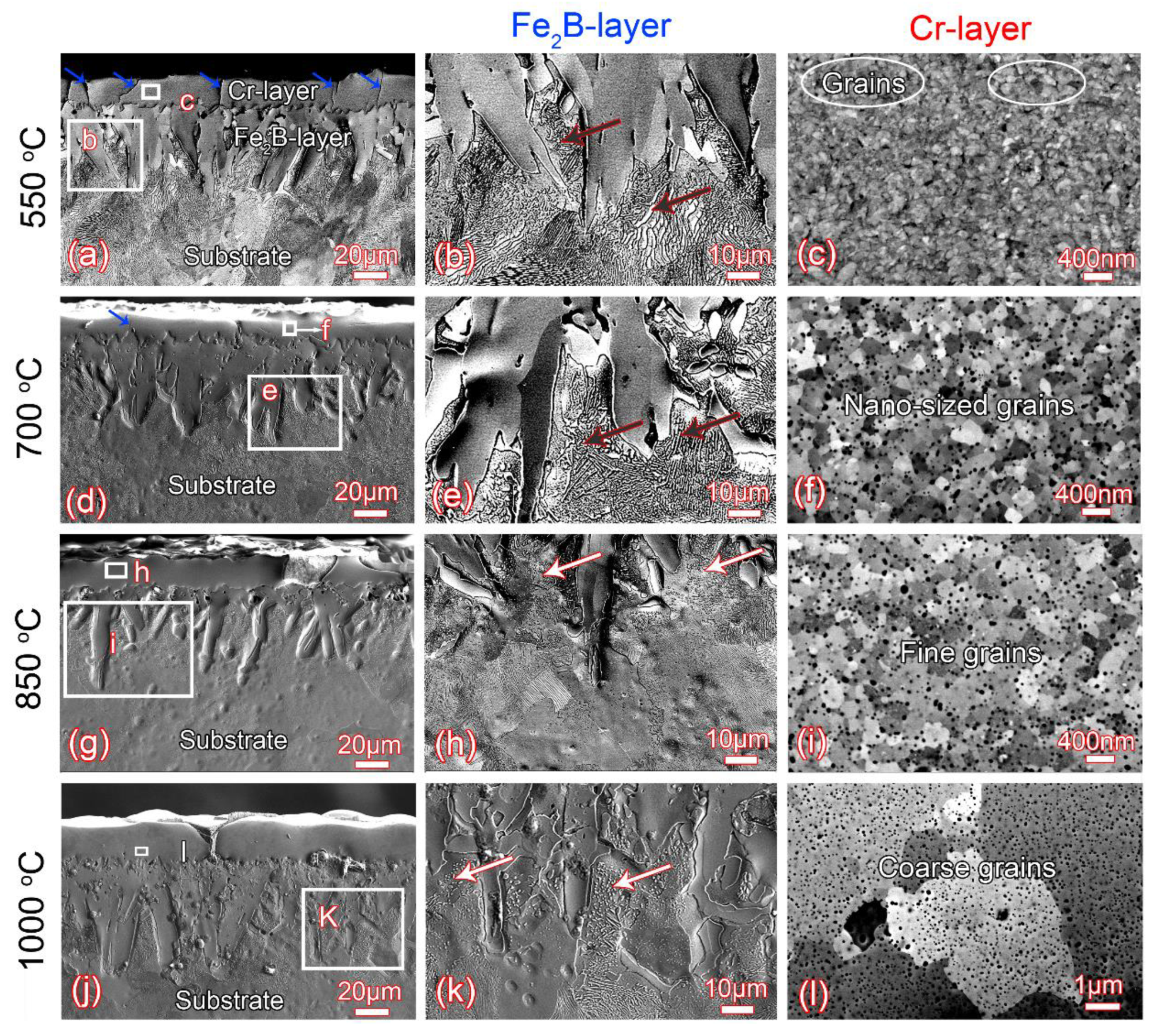
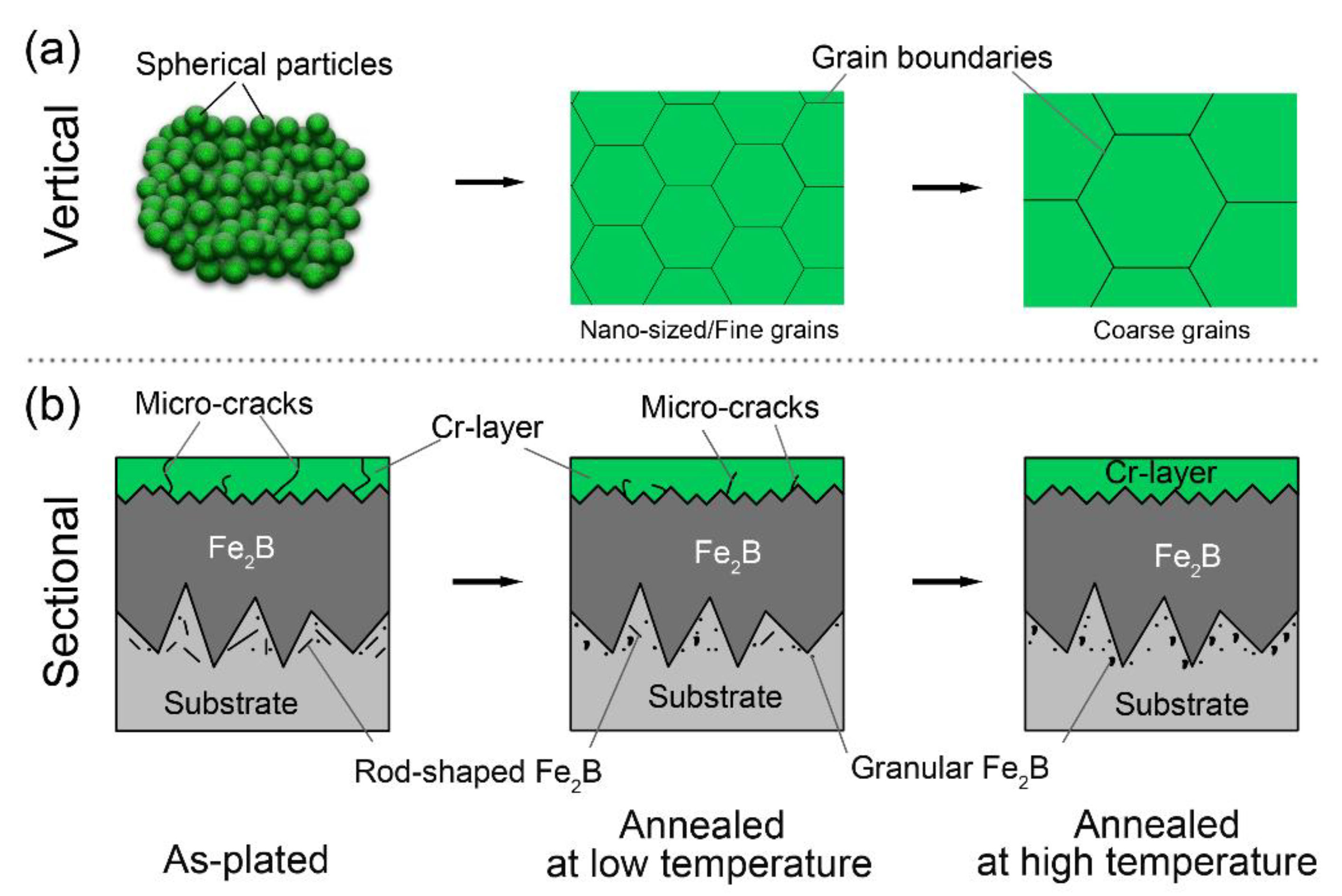
3.2. Microstructure Evolution during Annealing

Figure 3 shows the cross-sectional BSEI images of the coatings annealed at different temperatures. The gradient structure coatings composed of Cr-layer and Fe2B-layer show excellent thermal stability during annealing up to 1000 °C, and no new layers and/or transition layers are observed in the coatings, as shown in Figure 3a,d,g,j. The difference is that the microstructure and morphology of the Fe2B-layer and Cr-layer vary greatly with the increase of the annealing temperature. For the Fe2B-layer, the rod-shaped Fe2B particles formed during pack-preboronizing are still visible at low temperature annealing (see the dark arrows in Figure 3b,e), but transformed into spherical shapes at high temperature annealing (see the bright arrows in Figure 3h,k). This is because the growth and coarsening of the second-phase particles under high-temperature annealing are spontaneous processes, thereby reducing the total free energy of the system [36]. The transition between Fe2B particles occurs between 550 and 700 °C.
Figure 3c shows that the Cr-coating shows a mixed structure of granular amorphous and nano-sized grains (see white oval) after annealing at 550 °C, which indicates that the equiaxed nodule structure is partially crystallized under low temperature annealing. When the annealing temperature is increased to 700 °C, it has been completely crystallized, and nano-sized grains with an average diameter of approximately 210 nm can be clearly observed in the Cr-layer, as shown in Figure 3f. Compared to the A700 sample, the grain size of the A850 sample grows slightly into 300 nm, as shown in Figure 3i. As the temperature rises to 1000 °C, the grain size rapidly coarsens to 4 μm (see Figure 3l).
Additionally, the number of microcracks within the Cr-layer also changes remarkably with increase annealing temperature. As shown in Figure 3a, the cracks penetrate almost the entire cross section of the Cr-coating. Compared to the as-plated state, microcracks within the Cr-layer increases sharply after annealing at 550 °C. The increase of microcracks is due to the collapse of the voids and the grain growth of the spherical Cr particles during the annealing at low-temperature [8]. When the temperature exceeds 550 °C, the cracks become shorter and shorter, and no distinct cracks are observed in the A850 and A1000 samples. This is because, due to the high surface energy, the microcracks aggregate into larger pores or migrate to the surface of the material and disappear after high-temperature annealing [8]. After annealing at different temperatures, the substrate does not change significantly, and still exhibits a typical hypoeutectoid steel structure. Moreover, it has been reported that during thermal chromizing or annealing at high temperature, the C atoms in the substrate can be dragged into the Cr-coating to form chrome carbide, resulting in the formation of carbon-poor zone at the subsurface of the substrate [37]. In this study, no carbon-poor zones are observed in the substrate. This is because that the pre-deposited Fe2B-layer with high thermal stability prevents the reaction between C and Cr during annealing.
BSEI images and EDS line scans of various samples are shown in Figure 4. It shows that both the Fe2B-layer and Cr-coating exhibit good thermal stability during annealing. After brush-plating, there is no sign of diffusion between the Cr-coating and the Fe2B-layer (see line L1 in Figure 4a). And when the annealing temperature is increased to 700 °C, the diffusion between the Cr-coating and the Fe2B layer is still not obvious (see L2 in Figure 4b). When the annealing temperature rises to 1000 °C, the distribution of the Fe and Cr elements vary slightly at the interface (see L3 in Figure 4c), indicating that the interdiffusion occurs between the Cr-coating and Fe2B layer, but no significant new compounds is formed at the interface. As the annealing temperature increases, the diffusion between Fe and Cr elements becomes more and more obvious, and the metallurgical bonding between the coatings becomes stronger and stronger.
Figure 5 illustrates the microstructure evolution of the Cr-Fe2B dual-phase coating during annealing. After brush-plating, a Cr-layer consisting of spherical particles and some microcracks is formed on the surface of the pre-deposited Fe2B-layer, as shown in Figure 5a. When the annealing temperature is increased to 700 °C, the spherical particles become nanosized grains, and the number of microcracks is greatly reduced, as shown in Figure 5b.
As the annealing temperature continues to increase, the nanosized structure becomes unstable and coarsens rapidly. Meanwhile, the microcracks are reduced completely. In short, for the brush-plated Cr-layer, during the annealing process, in order to reduce the free energy of the system, the content of boundaries/cracks with high surface energy will be reduced, resulting in the formation and coarsening of grains and the reduction of microcracks [8]. Compared to the Cr-layer, the saw-toothed Fe2B-layer is almost unchanged during annealing due to its excellent thermal stability [38,39]. However, under the driving force of reducing the surface energy, the fine rod-like Fe2B phase located at the interface of the saw-toothed Fe2B grain and the substrate is transformed into granular Fe2B particles after high-temperature annealing.

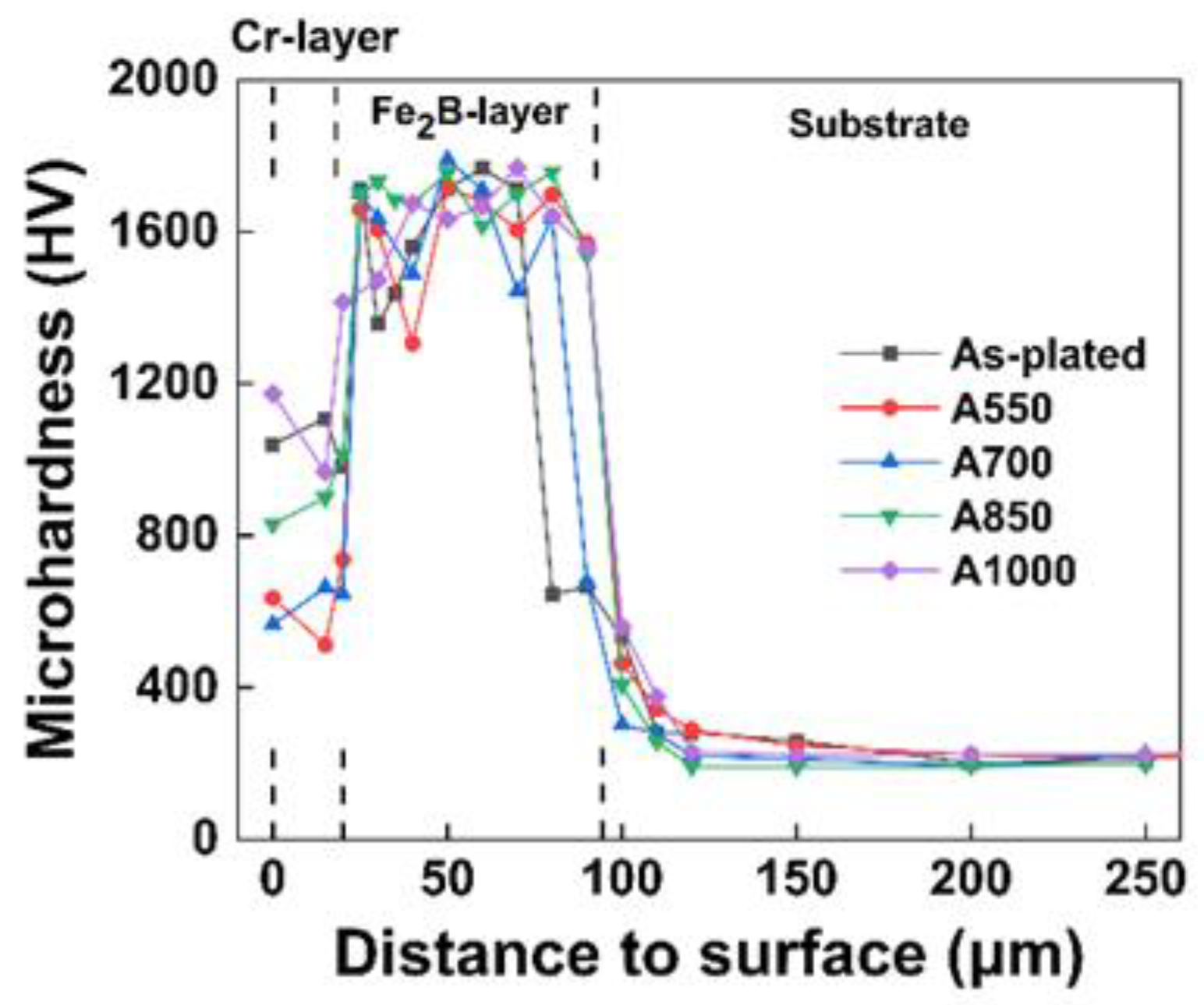
3.3. Microhardness Evolution after Annealing

Figure 6 shows the microhardness distribution along the depth direction after annealing at various temperatures. For the as-plated sample, the subsurface-layer has the highest hardness and gradually decreases in the depth direction. According to the microstructural observations (Figure 1, Figure 2 and Figure 3), the thickness of Cr-coating and Fe2B-layer is about 18 and 75 µm, respectively. Therefore, the subsurface layer with the highest hardness is the location of Fe2B phase. The Cr layer (0–18 µm) has the highest hardness before annealing due to the spherical Cr particles with nano size. This is because that although the Cr-coating has low density and many micro-cracks before annealing, the nano-sized spherical Cr particles constituting the coating are considered to be amorphous, which makes the Cr-layer present the highest hardness. When the annealing temperature is 550 °C, the hardness of the Cr-coating is very low. It is mainly attributable to the crystallization of amorphous spherical Cr particles and the increase of micro-cracks during low-temperature (≤ 700 °C) annealing [8]. When the temperature exceeds 700 °C, the hardness will increase as the annealing temperature increases. The hardness after 1000 °C annealing is very close to that of the as-plated sample, owing to the solid-solution strengthening of the Fe and the reduction of micro-cracks within the Cr-layer. For the Fe2B-layer (18–93 µm), as the annealing temperature increases, the hardness decreases gradually. This is because under the action of heat, the Fe2B-layer, the Cr-layer and the steel substrate diffuse with each other, and the Fe2B-layer is partially decomposed, resulting in the decrease in hardness. In addition, for the steel substrate, due to the short annealing time, the microstructure does not change much, so the hardness of the substrate away from the coating does not change significantly with increasing annealing temperature. Compared with the brush annealing process in which there is no intermediate layer in the references [8], the validity of the Fe2B-layer in blocking the formation of carbon-poor zones is verified by the hardness data in this paper.

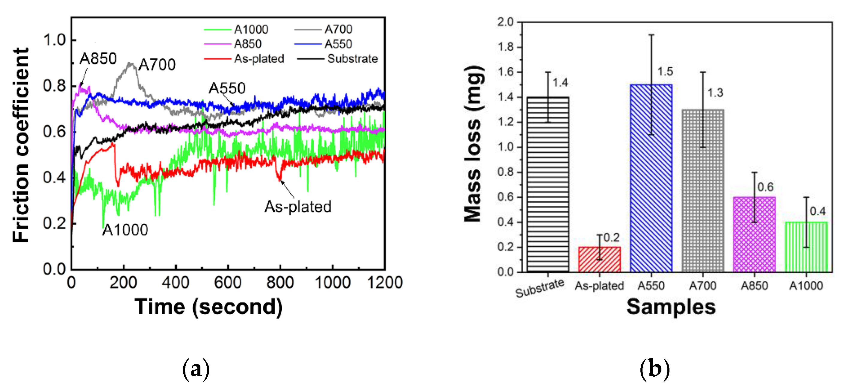
3.4. Friction and Wear Behavior

The friction coefficients plotted as a function of friction time for different samples are shown in Figure 7. The friction coefficient of the as-plated and A1000 is the smallest, followed by A850, and followed by A550, A700, and the uncoated samples, as shown in Figure 7a. There is a similar phenomenon in the mass loss (see Figure 7b). Generally, materials with a small friction coefficient have a small mass low of wear, while materials with a large friction coefficient have a large mass loss. The smaller the friction coefficient and the mass loss, the better the abrasion resistance, which indicates that the as-plated and A1000 samples have better wear properties compared to other samples. This is because the outermost Cr-layer of the as-plated and A1000 samples have higher hardness than other samples, and the wear resistance of the material depends largely on the hardness [40]. Figure 8 shows the wear morphology of different samples. Compared to the uncoated steel (Figure 8a), the as-plated (Figure 8b) and the annealed samples (Figure 8c–f) show narrower scars of wear. The width of the wear scar of the as-plated and A1000 samples is the narrowest, corresponding to better wear resistance.
It should be noted that generally annealing treatment can enhance the metallurgical bonding strength between the coating and substrate and improve the performance of the coating. However, in this study, the as-plated sample shows better wear resistance than the annealed samples. This may be because the load used in the friction and wear test is too small to reflect the influence of the bonding strength of the interface between the coating and the substrate on the wear resistance. The as-plated sample has good wear resistance owing to the high hardness of the amorphous structure of the Cr-layer in the as-plated sample.

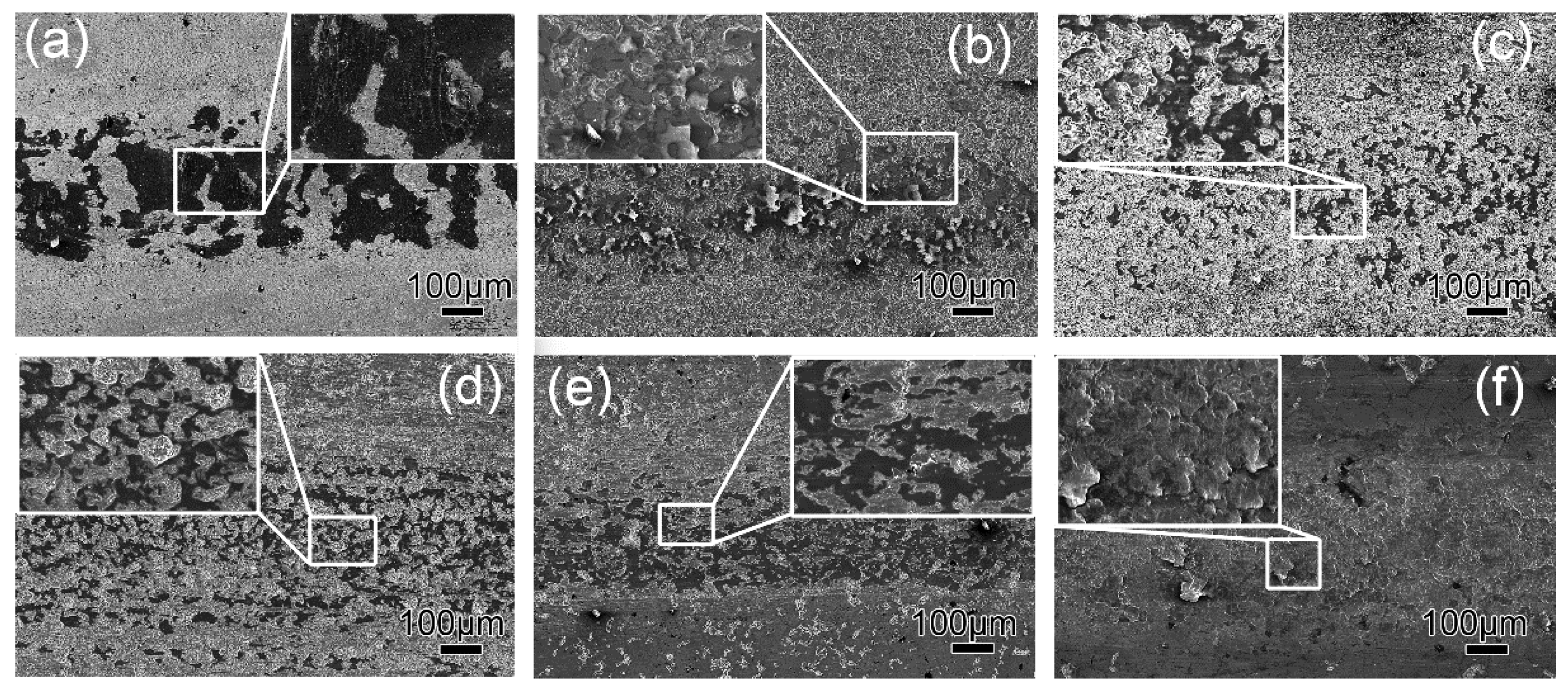
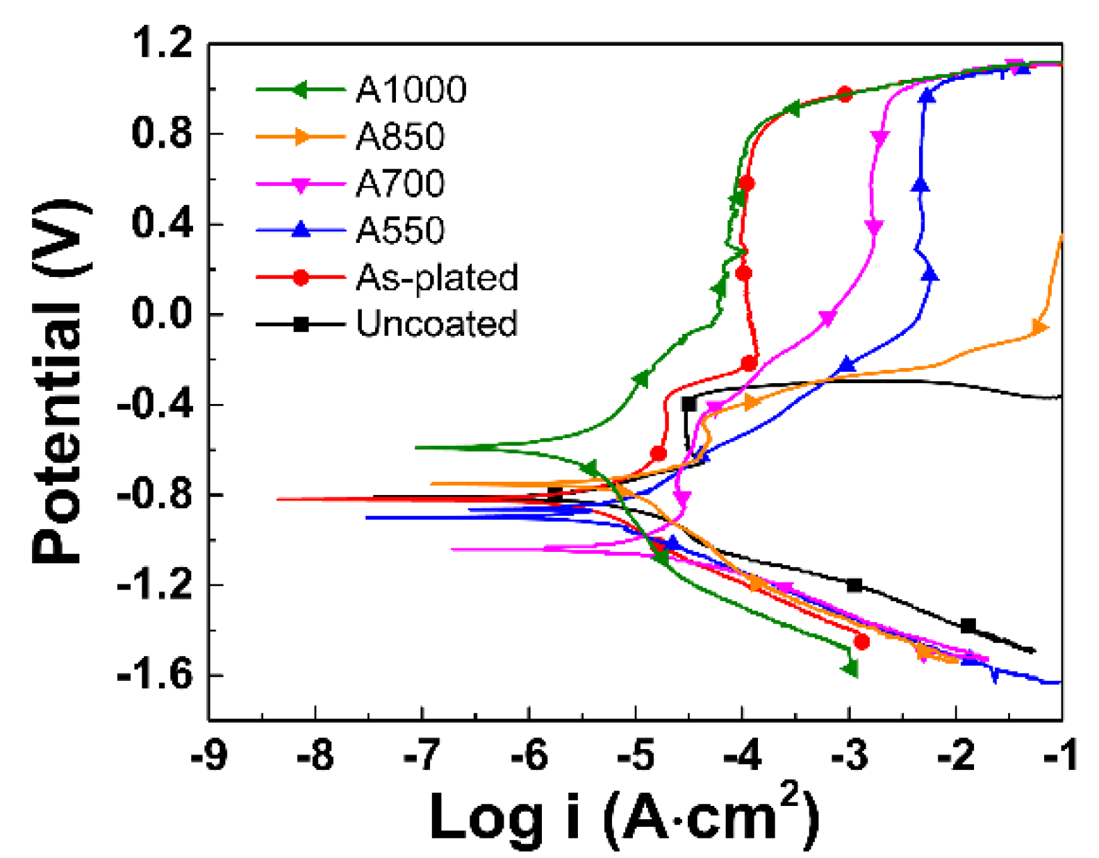
3.5. Corrosion Behavior

Figure 9 shows the potentiodynamic polarisation curves of various samples. All the polarisation data were measured by Tafel extrapolation method, and the corrosion rate (CR) was calculated by Faraday’s equation [28]:
C R ( mm / y ) = 3.27 × 10 3 × E W × I c o r r ρ
where EW is equivalent weight (28 g), Icorr is corrosion current density (μA/cm2), ρ is density (g/cm3). The obtained data are shown in Table 1. Compared to the uncoated steel, the Cr-Fe2B composite coating can greatly reduce the corrosion rate of the steel. The corrosion current density and corrosion rate of the as-plated sample are the lowest. This may be due to the amorphous structure of the Cr-layer after brush-plating. There are no crystalline defects in the amorphous coating, such as dislocations, grain boundaries, or second-phase precipitations which act as galvanic couples and sites for the onset of corrosion [41]. After annealing, the A550 sample has the lowest corrosion current density and corrosion rate compared to the other annealed samples. The better of corrosion resistance of the A550 sample can be attributed to the rapid formation of stable and dense passive film on Cr-layer consisting of nanocrystallized grains. It has been pointed out that the nanocrystallized grain surface behaves higher impedance, more positive corrosion potential and lower corrosion current density as compared with the coarse grain surface [42]. As the annealing temperature further increase, the corrosion rate first increases and then decreases. This is because when the annealing temperature reaches 700 °C, the grains of the Cr-coating are severely coarsened compared to the A550 sample and the number of micro-cracks are greatly increased, thereby accelerating corrosion. Because, the micro-cracks can act as a corrosion channel between the coating and the substrate, resulting in rapid corrosion of the coating and substrate [28]. When the temperature is increased to 1000 °C, the micro-cracks in the Cr-coating are reduced, resulting in improving the corrosion resistance again.

4. Conclusions

In this study, Cr-Fe2B composite coating was deposited on the surface of the AISI 5140 steel by pack-boronizing followed by electro brush-plating. The microstructure and properties of the coating annealed at different temperatures were investigated. The following conclusions can be drawn:
  • The brush-plated Cr-layer has an amorphous structure which is very stable under low temperature (≤550 °C) annealing. As the annealing temperature increases to 700 °C, the amorphous structure crystallizes into nanosized grains, and the nanocrystallized grains quickly coarsen into coarse grains with further increases in the annealing temperature.
  • The microcracks in the Cr-layer increase sharply after annealing at 550 °C and then decrease significantly with the further increase of the annealing temperature.
  • During the annealing process, the rod-shaped Fe2B particles are gradually transformed into granular Fe2B ones. The pre-deposited Fe2B-layer prevents the formation of carbon-poor zones during annealing. The pre-deposited Fe2B-layer with high thermal stability prevents the reaction between C and Cr during annealing, so that even after high-temperature annealing, no carbon-poor zones are formed in the steel substrate.
  • Annealing treatment can strengthen the metallurgical bonding strength and improve the bonding strength of the coating. It is considered that high-temperature (> 700 °C) annealing helps to eliminate coating defects and increase coating density and obtain better wear resistance and corrosion resistance.

Author Contributions

Conceptualization, J.H. and H.X.; methodology, Y.L., X.Y., and H.L.; software, N.G.; validation, X.Y. and J.H.; formal analysis, J.H. and N.G.; investigation, J.H., Y.P., and N.G.; resources, J.H. and H.X.; data curation, J.H. and N.G.; writing—original draft preparation, Y.P., C.H., and N.G.; writing—review and editing, N.G.; supervision, H.X.; project administration, J.H. and H.X.; funding acquisition, J.H., H.X., and N.G. All authors have read and agreed to the published version of the manuscript.

Funding

This work was co-supported by the Natural Science Foundation of China (51575073), Scientific and Technological Research Program of Chongqing (cstc2017jcyjBX0031), the Fundamental Research Funds for the Central Universities of China (No. XDJK2019B066), Scientific and Technological Research Program of Banan District of Chongqing (2018TJ06), the Graduate scientific research innovation project of Chongqing (CYS18308), and Program for Innovation Team Building at Institutions of Higher Education in Chongqing (CXTDG20162017).

Conflicts of Interest

The authors declare no conflict of interest.

References

  1. Ouyang, T.; Huang, G.; Chen, J.; Gao, B.; Chen, N. Investigation of lubricating and dynamic performances for high-speed spur gear based on tribo-dynamic theory. Tribol. Int. 2019, 136, 421–431. [Google Scholar] [CrossRef]
  2. Thiagarajan, D.; Vacca, A.; Watkins, S. On the lubrication performance of external gear pumps for aerospace fuel delivery applications. Mech. Syst. Signal Pr. 2019, 129, 659–676. [Google Scholar] [CrossRef]
  3. Li, B.; Sun, D.; Hu, M.; Zhou, X.; Liu, J.; Wang, D. Coordinated control of gear shifting process with multiple clutches for power-shift transmission. Mech. Mach. Theory 2019, 140, 274–291. [Google Scholar] [CrossRef]
  4. Hu, J.; Ma, C.; Xu, H.; Guo, N.; Hou, T. Development of a composite technique for preconditioning of 41Cr4 steel used as gear material: Examination of its microstructural characteristics and properties. Sci. Technol. Nucl. Install. 2016, 2016, 1–6. [Google Scholar] [CrossRef] [Green Version]
  5. Xu, H.; Hu, J.; Ma, C.; Chai, L.; Guo, N. Influence of electron beam irradiation on surface roughness of commercially AISI 5140 steel. Mater. Trans. 2017, 58, 1519–1523. [Google Scholar] [CrossRef] [Green Version]
  6. He, Q.; Paiva, J.M.; Kohlscheen, J.; Beake, B.D.; Veldhuis, S.C. An integrative approach to coating/carbide substrate design of CVD and PVD coated cutting tools during the machining of austenitic stainless steel. Ceram. Int. 2020, 46, 5149–5158. [Google Scholar] [CrossRef]
  7. Chou, C.-C.; Lee, J.-W.; Chen, Y.-I. Tribological and mechanical properties of HFCVD diamond-coated WC-Co substrates with different Cr interlayers. Surf. Coat. Technol. 2008, 203, 704–708. [Google Scholar] [CrossRef]
  8. Zong, L.; Guo, N.; Li, R.; Yu, H. Effect of annealing treatment on microstructure and properties of Cr-coatings deposited on AISI 5140 steel by brush-plating. Coatings 2019, 9, 265. [Google Scholar] [CrossRef] [Green Version]
  9. Ettefagh, A.H.; Wen, H.; Chaichi, A.; Islam, M.I.; Lu, F.; Gartia, M.; Guo, S. Laser surface modifications of Fe-14Cr ferritic alloy for improved corrosion performance. Surf. Coat. Technol. 2020, 381, 125194. [Google Scholar] [CrossRef]
  10. Wu, A.; Liu, Q.; Qin, S. Influence of yttrium on laser surface alloying organization of 40Cr steel. J. Rare Earths 2011, 29, 1004–1008. [Google Scholar] [CrossRef]
  11. Rai, A.K.; Biswal, R.; Gupta, R.K.; Rai, S.K.; Singh, R.; Goutam, U.K.; Ranganathan, K.; Ganesh, P.; Kaul, R.; Bindra, K.S. Enhancement of oxidation resistance of modified P91 grade ferritic-martensitic steel by surface modification using laser shock peening. Appl. Surf. Sci. 2019, 495, 143611. [Google Scholar] [CrossRef]
  12. Grabowski, A.; Sozańska, M.; Adamiak, M.; Kępińska, M.; Florian, T. Laser surface texturing of Ti6Al4V alloy, stainless steel and aluminium silicon alloy. Appl. Surf. Sci. 2018, 461, 117–123. [Google Scholar] [CrossRef]
  13. Lopez-Ruiz, P.; Garcia-Blanco, M.B.; Vara, G.; Fernández-Pariente, I.; Guagliano, M.; Bagherifard, S. Obtaining tailored surface characteristics by combining shot peening and electropolishing on 316L stainless steel. Appl. Surf. Sci. 2019, 492, 1–7. [Google Scholar] [CrossRef]
  14. Yang, C.; Liu, Y.G.; Li, M.Q. Characteristics and formation mechanisms of defects in surface layer of TC17 subjected to high energy shot peening. Appl. Surf. Sci. 2020, 509, 144711. [Google Scholar] [CrossRef]
  15. Gao, S.; Dong, C.; Luo, H.; Xiao, K.; Pan, X.; Li, X. Scanning electrochemical microscopy study on the electrochemical behavior of CrN film formed on 304 stainless steel by magnetron sputtering. Electrochim. Acta 2013, 114, 233–241. [Google Scholar] [CrossRef]
  16. Wang, M.; Zhou, Z.; Wang, Q.; Liu, Y.; Wang, Z.; Zhang, X. Box-behnken design to enhance the corrosion resistance of plasma sprayed Fe-based amorphous coating. Results Phys. 2019, 15, 102708. [Google Scholar] [CrossRef]
  17. Verhiest, K.; Mullens, S.; Graeve, I.D.; Wispelaere, N.D.; Claessens, S.; Bremaecker, A.D.; Verbeken, K. Advances in the development of corrosion and creep resistant nano-yttria dispersed ferritic/martensitic alloys using the rapid solidification processing technique. Ceram. Int. 2014, 40, 14319–14334. [Google Scholar] [CrossRef]
  18. Jin, G.; Lu, B.; Hou, D.; Cui, X.; Song, J.; Liu, E. Influence of rare earths addition on residual stress of Fe-based coating prepared by brush plating technology. J. Rare Earths 2016, 34, 336–340. [Google Scholar] [CrossRef]
  19. Zhang, D.; Cui, X.; Jin, G.; Cai, Z.; Lu, B. Microstructure and mechanical properties of electro-brush plated Fe/MWCNTs composite coatings. Surf. Coat. Technol. 2018, 348, 97–103. [Google Scholar] [CrossRef]
  20. Wu, B.; Xu, B.-S.; Zhang, B.; Jing, X.-D.; Liu, C.-L. Automatic brush plating: An update on brush plating. Mater. Lett. 2006, 60, 1673–1677. [Google Scholar] [CrossRef]
  21. Zhang, D.; Cui, X.; Jin, G.; Cai, Z.; Dong, M. Thermal stability of Ni-B/La2O3 coatings by electro-brush plating technique. Surf. Coat. Technol. 2018, 349, 1042–1047. [Google Scholar] [CrossRef]
  22. Han, Z.; Zuo, Y.; Ju, P.; Tang, Y.; Zhao, X.; Tang, J. The preparation and characteristics of a rare earth/nano-TiO2 composite coating on aluminum alloy by brush plating. Surf. Coat. Technol. 2012, 206, 3264–3269. [Google Scholar] [CrossRef]
  23. Jin, G.; Zhang, D.; Liu, M.; Cui, X.; Liu, E.; Song, Q.; Yuan, C.; Wen, X.; Fang, Y. Microstructure, deposition mechanism and tribological performance of graphene oxide reinforced Fe composite coatings by electro-brush plating technique. J. Alloys Compd. 2019, 801, 40–48. [Google Scholar] [CrossRef]
  24. Liu, H.; Wang, X.; Ji, H. Fabrication of lotus-leaf-like superhydrophobic surfaces via Ni-based nano-composite electro-brush plating. Appl. Surf. Sci. 2014, 288, 341–348. [Google Scholar] [CrossRef]
  25. Chen, T.; Ge, S.; Liu, H.; Sun, Q.; Zhu, W.; Yan, W.; Qi, J. Fabrication of low adhesive superhydrophobic surfaces using nano Cu/Al2O3 Ni-Cr composited electro-brush plating. Appl. Surf. Sci. 2015, 356, 81–90. [Google Scholar] [CrossRef]
  26. Tang, J.-L.; Zuo, Y.; Tang, Y.-M.; Xiong, J.-P. Composition and corrosion resistance of palladium film on 316L stainless steel by brush plating. Trans. Nonferrous Met. Soc. China 2012, 22, 97–103. [Google Scholar] [CrossRef]
  27. Zhong, Z.; Clouser, S.J. Nickel-tungsten alloy brush plating for engineering applications. Surf. Coat. Technol. 2014, 240, 380–386. [Google Scholar] [CrossRef]
  28. Hu, J.; Zeng, J.; Yang, Y.; Yang, X.; Li, H.; Guo, N. Microstructures and wear resistance of boron-chromium duplex-alloyed coatings prepared by a two-step pack cementation process. Coatings 2019, 9, 529. [Google Scholar] [CrossRef] [Green Version]
  29. Hu, J.J.; Chai, L.J.; Xu, H.B.; Ma, C.P.; Deng, S.B. Microstructural modification of brush-plated nanocrystalline Cr by high current pulsed electron beam irradiation. J. Nano Res. 2016, 41, 87–95. [Google Scholar] [CrossRef]
  30. Li, X.; Wang, X.; Gao, R.; Sun, L. Study of deposition patterns of plating layers in SiC/Cu composites by electro-brush plating. Appl. Surf. Sci. 2011, 257, 10294–10299. [Google Scholar] [CrossRef]
  31. Türkmen, İ.; Yalamaç, E. Growth of the Fe2B layer on SAE 1020 steel employed a boron source of H3BO3 during the powder-pack boriding method. J. Alloys Compd. 2018, 744, 658–666. [Google Scholar] [CrossRef]
  32. Kulka, M.; Makuch, N.; Piasecki, A. Nanomechanical characterization and fracture toughness of FeB and Fe2B iron borides produced by gas boriding of Armco iron. Surf. Coat. Technol. 2017, 325, 515–532. [Google Scholar] [CrossRef]
  33. Kartal, G.; Timur, S.; Sista, V.; Eryilmaz, O.L.; Erdemir, A. The growth of single Fe2B phase on low carbon steel via phase homogenization in electrochemical boriding (PHEB). Surf. Coat. Technol. 2011, 206, 2005–2011. [Google Scholar] [CrossRef]
  34. Keddam, M.; Kulka, M.; Makuch, N.; Pertek, A.; Małdziński, L.A. Kinetic model for estimating the boron activation energies in the FeB and Fe2B layers during the gas-boriding of Armco iron: Effect of boride incubation times. Appl. Surf. Sci. 2014, 298, 155–163. [Google Scholar] [CrossRef]
  35. Yu, L.G.; Chen, X.J.; Khor, K.A.; Sundararajan, G. FeB/Fe2B phase transformation during SPS pack-boriding: Boride layer growth kinetics. Acta Mater. 2005, 53, 2361–2368. [Google Scholar] [CrossRef]
  36. Usta, M.; Glicksman, M.E.; Wright, R.N. The effect of heat treatment on Mg2Si coarsening in aluminum 6105 alloy. Metall. Mater. Trans. A 2004, 35, 435–438. [Google Scholar] [CrossRef]
  37. Hu, J.; Wang, J.; Jiang, J.; Yang, X.; Xu, H.; Li, H.; Guo, N. Effect of heating treatment on the microstructure and properties of Cr-Mo duplex-alloyed coating prepared by double glow plasma surface alloying. Coatings 2019, 9, 336. [Google Scholar] [CrossRef] [Green Version]
  38. Martin, C.; Palombarini, G.; Poli, G.; Prandstraller, D. Sliding and abrasive wear behaviour of boride coatings. Wear 2004, 256, 608–613. [Google Scholar] [CrossRef]
  39. Campos-Silva, I.; Flores-Jiménez, M.; Rodríguez-Castro, G.; Hernández-Sánchez, E.; Martínez-Trinidad, J.; Tadeo-Rosas, R. Improved fracture toughness of boride coating developed with a diffusion annealing process. Surf. Coat. Technol. 2013, 237, 429–439. [Google Scholar] [CrossRef]
  40. Wei, S.; Zhu, J.; Xu, L. Research on wear resistance of high speed steel with high vanadium content. Mater. Sci. Eng. A-Struct. 2005, 404, 138–145. [Google Scholar] [CrossRef]
  41. Souza, C.A.C.; Ribeiro, D.V.; Kiminami, C.S. Corrosion resistance of Fe-Cr-based amorphous alloys: An overview. J. Non-Cryst. Solids 2016, 442, 56–66. [Google Scholar] [CrossRef]
  42. Jin, L.; Cui, W.F.; Song, X.; Liu, G.; Zhou, L. Effects of surface nanocrystallization on corrosion resistance of β-type titanium alloy. Trans. Nonferrous Met. Soc. China 2014, 24, 2529–2535. [Google Scholar] [CrossRef]
Figure 1. Microstructure observed from the cross-sectional views of the sample after pack-preboronizing treatment: (a) low-magnification image; (b) high-magnification image.
Coatings 10 00519 g001
Figure 2. Microstructure and morphology of the as-plated sample: (a) sectional view showing the coating and matrix; (b,d,e) partial enlarged view of corresponding part in (a); (c) enlarged views of the white box in (b); (f) top view showing equiaxed nodules. GB represents grain boundary.
Coatings 10 00519 g002
Figure 3. BSEI images showing microstructure of the composite coating with annealing temperature: (ac) A550; (df) A700; (gi) A850; (jl) A1000. Figures (b, e, h and k) are the bonding regions of Fe2B layer and matrix corresponding to (a, d, g and j), respectively. Figures (c, f, i and l) are the corresponding enlarged images of (a, d, g and j), respectively. The blue arrows indicate microcracks.
Coatings 10 00519 g003
Figure 4. EDS results: Figure (a), (b)and (c)showing the cross sections of the combination of Cr-coating and Fe2B layer of the as-plated, A700 and A1000, respectively.
Coatings 10 00519 g004
Figure 5. Schematic diagram illustrating microstructure evolution of the Cr-Fe2B dual-phase coating during annealing: (a) vertical view; (b) sectional view.
Coatings 10 00519 g005
Figure 6. Microhardness evolution with increasing annealing temperature.
Coatings 10 00519 g006
Figure 7. Friction coefficient plotted as a function of sliding friction time (a) and weight loss (b) of various samples.
Coatings 10 00519 g007
Figure 8. Wear morphology of various samples: (a) uncoated steel; (b) as-plated; (c) A550; (d) A700; (e) A850; (f) A1000.
Coatings 10 00519 g008
Figure 9. Potentiodynamic polarisation curves of various samples.
Coatings 10 00519 g009
Table 1. Corrosion potential (Ecorr), corrosion current density (Icorr) and average corrosion rate (CR) of samples.
SamplesEcorr(mV)Icorr (μA/cm2)CR (mm/y)
A1000−59319.30.225
A850−75322.40.261
A700−104027.60.322
A550−8983.100.036
As-plated−8202.310.027
Uncoated−80953.20.621

