Abstract
This study proposes the development of new architectures that combine nanostructured titanium surface and biodegradable polymers as a promising approach to achieve a better performance after bioactive agent incorporation. The silk fibroin protein that was extracted from silkworm Bombyx mori cocoons is important due to the remarkable characteristics, such as biocompatibility, good mechanical properties, adjustable degradation and drug stabilizing capabilities. The titanium substrate was firstly nanostructurated with TiO2 nanotubes and then coated with silk fibroin using electrospinning and electrochemical deposition. The deposited silk film ability to become a bioactive implant coating with antibacterial properties after the encapsulation of the active agents such as CeO2 was investigated. Important features of the new implant coating were analysed: surface properties, electrochemical stability in physiological simulated electrolytes, and antibacterial action against Escherichia coli. The obtained results indicate that silk fibroin bioactive layers are a potential candidate for regenerative medicine.
1. Introduction
In recent years, the number of persons who require orthopaedic implants has grown and this fact leads to the development of a new concept of biomaterials that are capable of exerting better interactions with the surrounding tissue. Metallic implants for orthopaedic and dental applications are usually made of titanium or its alloys, as base materials, because they possess excellent mechanical properties and corrosion resistance. These materials intend to overcome the most commonly occurring causes for unsuccessful implants integration, such as weak osseointegration and infections caused by bacteria. Metal-based bone implants are commonly used in bone surgical procedures because they have the suitable required properties from different points of view. For hard tissue implants (for example orthopaedic and dental), titanium (Ti) and its alloys are key materials presenting optimum physico-chemical and biocompatibility characteristics [1,2,3,4]. Despite this, their surface is less reactive since the natural TiO2 layer that forms in the atmosphere is bio inert. Thus, research efforts have focused on modifying the surface properties of titanium to control the interaction between the implant and its biological surrounding by surface modification with bioactive substances that will promote a rapid integration within the surrounding bone tissues. Modifications of the titanium surface can be made by different treatments: physical, chemical or complex coatings. These treatments lead to an appropriate surface morphology or entrapment of bioactive agents to improve integration and are focused principally on topography and composition of the implant surface, for an efficient immobilization of active agents [5,6,7,8,9,10,11,12,13].
In recent decades, nanostructured surfaces are of great interest since the cellular components interact with the biomaterial topographies at this nano-level. Consequently, different surface patterning methods have been used to fabricate appropriate nano-topographies for successful living tissue response. Among all already developed methods employed for nanoscale Ti surface engineering, Ti anodization represents one of the most affordable ways to achieve and control structures of this kind [4,14,15,16,17,18,19,20]. This implies the use of a two electrodes electrochemical cell where Ti is anodically oxidized, resulting a surface covered with self-organized titanium dioxide nanotubes (NT). By modifying the anodization working conditions (applied voltage, the duration of the experiment and electrolyte composition), nanotubes with various diameters (between 15 to 300 nm) and lengths (depending upon the anodization time) can be obtained [21].
Therefore, due to the facilities offered by these nanostructures, it started the development of new architectures that combines NT and biodegradable polymers as a promising approach to achieve a better performance for drug incorporation [22,23,24]. Thus, many different natural or synthetic polymers (some examples being: collagen, chitosan, poly(L-lactide) or poly(ε-caprolactone)) have been already utilized in biomedical applications that implies bone replacements or regenerations [25,26]. However, natural biopolymers have become more interesting to researchers because of their similar characteristics to the bone extracellular matrix and cytocompatibility. Among biodegradable polymers, the silk fibroin obtained from Bombyx mori silkworm is most widely used as a suitable candidate for use in fabrication of 3D porous scaffolds, due to its excellent biocompatibility, exceptional mechanical properties, easy processability, tunable degradation and ease of processing. Since silk fibroin obtained U.S. Food and Drug Administration (FDA) approval as a biomaterial [27,28], it can be tailored under various forms: hydrogels, sponges, microspheres, electrodeposited films and electrospun fibres [29]. It presents good mechanical properties: a random silk fibroin fibre mat was found to have ultimate tensile strength of 2.31 MPa and Young’s modulus 24.05 MPa [30]. Moreover, the silk fibroin films allows the incorporation of appropriate drugs (chemical compounds like Emodin) or bioactive compounds (growth factor) due to its amino acid sequence [31].
Despite the progress in polymer coatings on Ti or Ti alloys, including silk fibroin, which showed a strength value increased to a maximum of approximately 7.5 ± 1.0 MPa [32], there remain more challenges to solve regarding the fibroine adhesion on the titanium substrate. The poor bonding between polymers and metal substrates that make coatings easy to peel, can be overcome by the already created TiO2 nanostructure on Ti. TiO2 nanotubes are known to have –OH groups on their surface and these represent the anchoring groups for the organic compounds with carboxylic groups [33] such as silk fibroine (which have ~5525 amino acids with 77 carboxylic groups from a 737 groups per chain) [34]. In this way, nanostructuration could enhance the interactions between metals substrates and polymeric films, thus assuring a better linking between these two different materials. The titanium nanotubes play a double role by reducing the inert property of pure Ti and being an interface for silk fibroin bonding on pure Ti.
In the present study, titanium surface modification with fibroin was performed. Regarding the method of fibroin deposition, two kind of methods were discussed: electrospinning and electrochemical deposition. Electrospinning has been widely utilized to generate continuous polymeric nanofibers for bone tissue engineering applications [35], because it is a cost effective and simple technique that creates a proper structure mimicking the extracellular matrix (ECM) for cell migration and adhesion. On contrary, electrochemical deposition from silk fibroin solution is still not enough discussed in literature. Ti surface was firstly nanostructured with TiO2 nanotubes and then modified with a natural compound, silk fibroin extracted from Bombyx mori cocoons, using the two mentioned methods. The new obtained surfaces properties were evaluated using scanning electron microscopy (SEM), spectral analysis (Fourier transform infrared (FTIR) and energy-dispersive X-ray), wettability degree and characterization from the point of view of electrochemical behaviour.
Peri-implant infections can be controlled by treatments that reduce the presence of pathogens. So far, different decontamination techniques in case of biofilm colonizing the titanium surfaces (that do not change the surface alloy composition) were applied such as: immersion in different calcifying solutions [36] and the use of 14% doxycycline gel [37,38]. In this study, ability of fibroin film for antibacterial compounds incorporation was also discussed. CeO2 nanoparticles were successfully incorporated during the deposition procedure. The antibacterial effect of hybrid nanostructured coatings was evaluated.
2. Materials and Methods
2.1. Preparation of Ti Substrate
The metallic substrates consisted in titanium plates of 1 cm × 1 cm, 0.89 mm thickness, and 99.7% purity (Alfa Aesar Co., Haverhill, MA, USA). These were polished with CarbiMet (Buehler, Lake Bluff, IL, USA) abrasive discs (based on silicon carbide) starting with P320 and finishing with P1200. Afterwards, all remained impurities on the plates were ultrasonically removed with purified water (from a Millipore Direct-Q UV3 purification unit, Burlington, MA, USA), ethanol and acetone (in rounds of 15 min) and then drying.
2.2. Preparation of Ti/TiO2 Nanotubes
Anodization was conducted in a single compartment electrochemical cell having two electrodes: prepared titanium substrate mounted as the working electrode and a Pt rod (Metrohm, Herisau, Switzerland) as counter electrode. Mixed electrolyte based on ethylene glycol (Chimreactiv SRL, Bucuresti, Romania) with flour ions (0.5 wt.% NH4F—Sigma Aldrich, St. Louis, MO, USA) and small water amount (2% v/v) was used. Using a MATRIX MPS-7163 power source (Matrix, Lisbon, Portugal), the voltage applied between the two electrodes was raised in small steps (2 V/10 s) up to 30 V and then kept constant. The total run time of the experiment was 2 h, under ambient conditions. After 2 h, the Ti/TiO2 nanotubes samples were rinsed with plenty of water and ultrasonicated for 20 s in purified water for removal of the traces of anodizing electrolyte. These samples were named Ti_NT.
2.3. Synthesis of Fibroin
The fibroin deposited on Ti nanostructured surfaces was experimentally extracted from Bombyx mori cocoons following a protocol proposed in the specialized literature [29] and involved three main stages:
- Degumming of silk fibroin from Bombyx mori cocoons. These involved firstly the larvae extraction and cutting the cocoons into small pieces to ensure the efficiency of the cocoon boiling process, diminishing the chances of forming dense areas of fibroin which subsequently slow down the dissolving process and removing the sericin. Then, the cut cocoons were added to a 0.02 M sodium carbonate (Na2CO3) aqueous solution, when it reached the boiling point. The boiling time for the cocoons was 30 min. This process was followed by fibroin rinsing to remove the excess of Na2CO3. The rinsed fibroin is left to dry at room temperature.
- Dissolving of silk fibroin. The dried fibroin was then dissolved with a 9.3 M lithium bromide (LiBr) solution. The solution was added dropwise over the dried fibroin, previously introduced into a Berzelius beaker. The dissolution process was completed by keeping the silk fibroin at 60 °C in an oven, until an amber colour was obtained for the dissolved fibroin.
- The last step was the purification of silk fibroin. This step was carried out by means of a dialysis process (48 h), because in medical applications the total removal of LiBr is necessary. The fibroin solution obtained after the dissolution step was introduced into a dialysis cassette. The purification took place under continuous stirring in a Berzelius beaker containing ultrapure water that was changed at least six times within 48 h.
The obtained fibroin solutions had concentrations between 7% and 8.5%, values that are like those observed in the literature. The fibroin solution was kept at low temperatures in the refrigerator and used for deposition.
2.4. Deposition of Silk Fibroin Films on Titanium and Titanium Oxide Nanotubes
Silk fibroin films were deposited using two procedures:
- Electrodeposition
The electrolyte used was a 3% solution of fibroin, and citric acid was added to adjust the pH of the solution to a value of 3.5. With an MPS-6005L-2 (Matrix Orbital) power source, electrodeposition was performed at 20 V for 20 min, at room temperature. A two electrode cell configuration, having a Pt plate as counter electrode was used. After deposition, the fibroin films were dried by keeping them at room temperature, immersed in methanol (80%) and stored in the freezer overnight. This treatment will turn the deposited fibroin into water insoluble films. Resulting samples were named Ti_SFech and Ti_NT_SFech when Ti and Ti_NT were used as working electrodes.
Samples containing CeO2 were also prepared by ultrasounds dispersing the CeO2 nanopowder (Alfa Aesar) in the electrolyte, up to 0.5 mg/mL CeO2. Fibroin containing CeO2 was deposited only on nanostructured samples (Ti_NT) using the same electrodeposition parameters. These samples were named Ti_NT_SFech_CeO2.
- Electrospinning
To obtain nanofibers, the fibroin solution containing 7%–8% fibroin was used. 5 wt.% poly(ethylene oxide) (PEO, Sigma Aldrich) was added as a carrier polymer. 1 mL of solution was loaded in a plastic syringe. A syringe pump (Legato 180 from KDS Scientific, Holliston, MA, USA) allowed the control on the volume of liquid with a flow rate of 0.5 mL/h. Between syringe stainless-steel blunt tip needle and grounded copper collector plate, 10 kV were applied using PS/EJ30P20 high voltage DC power supply (Glasmann High Voltage Inc, High Bridge, NJ, USA) for 10 min. The collector plate was arranged at 10 cm away from the tip of the syringe needle. Ti or Ti_NT samples were fixed on the collector plate to obtain Ti_SFes and Ti_NT_SFes samples. After fibroin electrospinning, samples were dried at room temperature. Subsequently, samples were immersed in methanol 90% for 20 min followed by 24 h ultrapure water immersion under magnetic stirring (for PEO removal).
In a similar way, hybrid coatings were obtained depositing fibroin from a solution with ultrasound dispersed CeO2, on top of Ti_NT. Resulting samples were called Ti_NT_SFes_CeO2.
2.5. Samples Surface Characterizations
The morphology of modified samples was observed using scanning electron microscopy (SEM). Ultra-high-resolution images were recorded with a FEI QUANTA 650 FEG (Hillsboro, OR, USA, SEM with Field Emission Gun) in high vacuum, at different magnifications. One of each type of samples were analysed: Ti_NT, Ti_SFech, Ti_SFes, Ti_NT_SFech, Ti_NT_SFes under following experimental conditions: HV 30 kV, WD was 10 mm and magnifications were between 2800×–200,000×, depending on sample. Energy-dispersive X-ray (EDX, Oxford X-max 80 SDD, Termo-Fischer Scientific, Hillsboro, OR, USA) analysis was also performed on one of each type of samples with CeO2: Ti_NT_SFech_CeO2 and Ti_NT_SFes_CeO2.
The attenuated total reflection Fourier transformed infra-red (ATR/FT-IR) study was performed using a Perkin Elmer Spectrum 100 spectrophotometer (Waltham, MA, USA). One of each type of samples were analysed: Ti_SFech, Ti_SFes, Ti_NT_SFech, Ti_NT_SFes. The wavenumbers domain selected for IR spectra collection was between 4000 and 600 cm−1. The spectra presented were recorded with 4 cm−1 resolution, and they are an average of four consecutive scans, with automatic baseline correction and automatic smooth.
A CAM 100 provided by KSV Instruments (Helsinky, Finland) was used for contact angle measurements. Three of each type of samples were analysed: Ti_NT, Ti_SFech, Ti_SFes, Ti_NT_SFech, Ti_NT_SFes. A Hamilton glass blunt tip syringe allowed 3–5 µL water droplet formation. A photo camera recorded the drop image and Cam 100 software (version 2.1.1) determine the contact angle (θ)—sessile drop method. The five measurements for each sample studied were performed in daylight, at room temperature. With the Excel program, the mean value and standard deviation were calculated.
2.6. Electrochemical Characterization
Electrochemical stability was evaluated using a configuration with three electrodes, having tested samples (one of each: Ti, Ti_NT, Ti_SFech, Ti_SFes, Ti_NT_SFech, Ti_NT_SFes) as working electrodes. The electrode/electrolyte interface was only 0.38 cm2 from working electrode surface. The other two electrodes were a Pt rod counter electrode and an Ag/AgCl, 3 M KCl reference electrode (both of them from Metrohm). Electrochemical cell was connected to an Autolab potentiostat/galvanostat, model PGSTAT 302N (Metrohm). Polarization curves at low scan rate (2 mV/s) were recorded from ±150 mV vs. OCP, and the corrosion parameters were determined from potential vs. log I (Tafel) representations. The electrochemical impedance spectra at OCP were recorded at room temperature, in 0.1–105 Hz frequency domain. The acquisition of the signal was made with an amplitude of 10 mV. NOVA 1.11 software allowed data processing to obtain all the parameters of interest. The electrolyte was Ringer’s solution (potassium chloride (0.3 g/L), calcium chloride dihydrate (0.33 g/L), sodium chloride (8.6 g/L) where ion concentration was as follows: sodium: 147 mmol/L, potassium: 4 mmol, calcium 2.3 mmol/L, chloride: 155.5 mmol/L), which contained components found in physiological liquids.
2.7. Antibacterial Assay
In vitro antibacterial effect associated with the test samples was performed versus the pathogenic bacterium Escherichia coli ATCC 8738.
Escherichia coli is a gram-negative bacterium, part of the Enterobacteria group. This microorganism is not always confined to the intestine, being capable to survive outside the body for short periods of time. It represents one of the most common infectious agents for implants [39].
Bacterium was cultured at 37 °C on the Luria Bertani (LB) culture medium which contain: peptone, 10 g/L; yeast extract 5 g/L, 5 g/L NaCl, 20 g/L agar [40,41]. Bacterial cultures were kept at 4 °C.
In vitro antibacterial activity was performed using two quantitative methods: percentage reduction test and the percentage inhibition of growth. Each of the two types of tests were performed in triplicate on the following types of samples: Ti_NT_SFes, Ti_NT_SFes_CeO2, Ti_NT_SFech and Ti_NT_SFech_CeO2.
For the first method, percentage reduction test [42], 4 µL of Escherichia coli solution was pipetted onto tested samples. After 3 h, 10 mL of sterile water was added to the solution, and then fully vibrated in order to harvest of the cells. Agar plates were inoculated by pipetting 1 mL of each rinse. Reduction in Escherichia coli concentration registered for each of the four samples (Ti_NT_SFes, Ti_NT_SFes_CeO2, Ti_NT_SFech and Ti_NT_SFech_CeO2) was compared with control sample. The efficiency of the antimicrobial test was determined, express as reduction percentage in a standard time. Inoculated agar plates were placed for 18 h in an incubator at 37 °C to determine the number of bacteria expressed in colony forming units (CFUs) [43].
The following equation was used for antibacterial effect calculation (bactericidal ratio), for each sample:
where R is bactericidal ratio (%).
In this study, we suggest for the estimation of the antimicrobial activities of cerium oxide nanoparticles to use the nanoparticle susceptibility constant as a quantitative parameter. This parameter, denoted by Z and having as unit of measure mL/μg, is calculated as follows [44]:
where N and N0 are the bacterial CFUs on the agar plate containing nanoparticles and pure agar plate respectively, and C is nanoparticles concentration expressed in μg/mL.
The survival fraction (N/N0) can be determined from Equation (2), using the nanoparticle susceptibility constant Z value and a known C value.
A high value of Z means a greater susceptibility of the microorganism to that material, or in other words, that material is more toxic for tested bacteria.
The percentage inhibition of growth, I% [45]:
where I is the percentage inhibition of growth, B18 is the blank-compensated optical density at 600 nm, B0 is the blank-compensated OD600 of the positive control of the organism at 0 h, C18 is the negative control-compensated OD600 of the organism in the presence of test sample at 18 h and C0 is the negative control-compensated OD600 of the organism in the presence of test sample at 0 h.
I% = [(B18 − B0) − (C18 − C0)]/(B18 − B0) × 100%
Briefly, for this second method, 5 mL of sterile Luria-Bertani broth inoculated with bacteria (1%) was added over sterile samples and allowed to incubate for 18 h in a Laboshake Gerhardt shaker at 37 °C and 200 rpm. Optical density measurements at 600 nm, allowed the bacterial growth to be determined for the samples and control (bacteria culture without sample). A UV-VIS spectrophotometer (Jenway Spectrophotometer, Staffordshire, UK) was used in this study.
3. Results and Discussion
3.1. Titanium Surface Modification
3.1.1. TiO2 Nanotube Growing
In Figure 1, SEM images for titanium dioxide nanotubes obtained by electrochemical anodization and ultrasonication can be observed. To obtain homogeneous surfaces, anodised titanium samples were ultrasonicated for 30 s to remove the “nanograss”. The surface is covered entirely with self-organized nanotubes. In images obtained at low magnitude (Figure 1a,b), it can be noticed that titanium dioxide nanotubes had different heights but uniform diameters. In Figure 1c the interior diameters value of uniform distributed nanotubes were comprised between 50–60 nm, while the external diameter reached up to 70 nm.
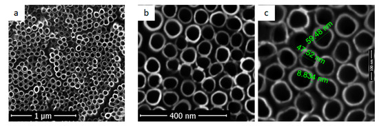
Figure 1.
SEM images for titanium dioxide nanotubes (Ti_NT sample) at different magnifications: (a) 30,000×; (b) 100,000×; (c) 300,000×.
Obtaining homogeneous surfaces is essential for the deposition of fibroin films, thereby providing an increased specific surface area and many fibroin binding sites. Surface roughness measured using atomic force microscopy for Ti substrate, Ra was 39 nm and for Ti_NT, was more increased, up to 192.7 nm. Similar tendency (increased Ra values for NT coated Ti compared to uncoated Ti) was also reported in other studies [23].
3.1.2. Electrochemical Deposition of Fibroin on Ti and Ti_NT
The unmodified titanium surfaces were electrochemically coated with fibroin films. SEM images showing a uniform and transparent fibrous film deposited on titanium substrate are presented in Figure 2a,b. The initial topography of the substrate resulted after the polishing step can be seen through the fibroin film. The like-pore structures formed on the surface in the fibrous film have different dimensions, in the order of the micrometres. In addition, their distribution on the analysed surface was not uniform.
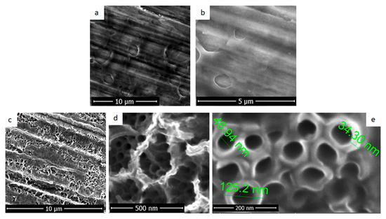
Figure 2.
SEM images for deposition of fibroin by electrochemical method (a,b): on titanium and (c–e) nanostructured titanium.
Figure 2c–e presents images for fibroin films deposited by electrochemical method on titanium substrate nanostructured with TiO2 nanotubes. Even the deposition parameters were similar with the ones used for Ti coating, a different morphology was obtained. A microporous structure with diameters around several hundreds of nanometres was formed over the TiO2 nanotubes. As it can be observed in Figure 2d, practically, the fibroin seemed to be anchored through nanotubes. The interior diameter of nanotubes (Figure 2e) was reduced to 40–50 nm after the electrochemical deposition of fibroin and the thickness of the walls increased over 30 nm. No spaces could be observed between nanotubes of titanium dioxide suggesting the deposition of fibroin between and within the TiO2 nanotubes.
Surface and pore size uniformity are essential for cellular response. Its lack can lead to different cell behaviour depending on the pores size which is undesirable in the case of orthopaedic implant surfaces.
3.1.3. Electrospinning Deposition of Fibroin on Ti and Ti_NT
In Figure 3, the substrate pre-treatment influence on the morphology of electrospun deposited fibroin was clearly visible.
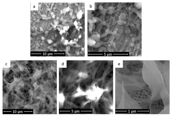
Figure 3.
Scanning electron microscopy images obtained for samples in which the deposition of fibroin films was performed by electrospinning on: (a) and (b) non-structured Ti substrates and (c–e) nanostructured Ti with titanium dioxide nanotubes.
In Figure 3a,b, deposition was performed on the titanium sample without a nanostructured surface. The fibroin fibres completely covered the titanium sample, but scratches left after Ti substrates polishing were visible. A porous film was obtained. Fibres with thicker parts (defects, beds) and agglomerations could be observed. They showed a fusiform morphology, with a maximum diameter of spindle of about 1 μm and extension thicknesses between 70 and 80 nm.
In contrast, in deposition on nanostructured titanium (Figure 3c–e), fibroin covers titanium dioxide nanotubes and a sponge-like porous structure is obtained. A dense layer of interconnected fibroin fibres (luminous areas) with very different thicknesses and lengths could be observed, Figure 3c,d. They were uniformly distributed on top of nanotubes (Figure 3e) creating a combination of the micro and nano scale dimensions. This is particularly important because the surface obtained from the modifications did not have a single morphology, which can be beneficial for cells. It is possible that in the bone tissue, a certain type of proteins or cell prefers the porosity of the fibroin film formed directly on the titanium dioxide nanotubes, while another type of cell prefers fusiform morphology and fibre extensions of fibroin deposited.
3.2. Samples Characterizations
3.2.1. FTIR Spectra
According with the literature, two fibroin conformations can be encountered. The β-sheet conformation presented peaks in the range of 1616–1637, 1513–1525 and 1265 cm−1 corresponding to amides I, II and III, respectively. Random coil/α-helix conformation showed peaks in the range of 1638–1660, 1536–1545 and 1235 cm−1 for amides I, II and III respectively [46].
FTIR spectra for the initial fibroin solutions obtained immediately after the dialysis step (SF 7.7% sol) and the solutions used for electrochemical (SF 3% ech. sol) and electrospinning (SF 7.7% es. sol) depositions, are presented in Figure 4. All spectra showed specific peaks of the random coil/α-helix structure: 1638, 1543 and 1245 cm−1 corresponding to the amides I, II and III respectively. The latter value, specific for type III amide, was close to 1243 cm−1, a value found in the literature for random III type amide [46,47].
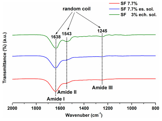
Figure 4.
FTIR spectra for fibroin solutions before using them for SF film deposition.
The FTIR spectra obtained for fibroin-coated titanium samples (Figure 5) show the specific β-sheet conformation peaks: 1699, 1625 and 1618 cm−1 (corresponding to amide I), 1523 cm−1 (corresponding to amide II) as well as 1265 and 1232 cm−1 (corresponding to amide III) [48]. The above-mentioned aspects and the peaks shifting suggest a conformational transition from the random coil for fibroin solutions to the β-sheet for the fibroin coatings on titanium substrates. This confirms the effectiveness of methanol treatment required for fibroin insolubility in water. Thus, the formation of hydrophobic zones (crystals β-sheets) was provided by this treatment.
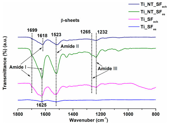
Figure 5.
FTIR spectra for fibroin-coated titanium samples.
3.2.2. Contact Angle Measurements
Table 1 presents the variation of the contact angle depending on the type of surface modification. For titanium substrates modified with titanium dioxide nanotubes by electrochemical anodization (Ti_NT), the average contact angle was 21° indicating a hydrophilic surface, as is already known in the literature [49,50].

Table 1.
Values of contact angles and standard deviations for titanium modified samples.
All titanium samples coated with fibroin showed more increased contact angle values compared to the Ti_NT sample. The higher contact angle values can be a cause of hydrophobic areas of the fibroin structure (crystalline β-sheets) obtained after methanol treatment.
The contact angles values for electrochemical deposited fibroin (Ti_SFech-57°, Ti_NT_SFech-69°) were higher than those obtained for the electrospun deposited fibroin (Ti_SFes-27°, Ti_NT_SFes-47°). This could be explained by the fact that Ti_SFes and Ti_NT_SFes needed 24 h water immersion for PEO removal. Contact angle for electrospun deposited fibroin samples after PEO removal was lower compared with other samples. This is in good agreement with literature data which show an enhanced wettability for fibroin fibers after PEO removal, which can be ascribed to the increased surface roughness of the fibers after PEO extraction, given the intrinsic hydrophilicity nature of the SF coating [30]. Although SF itself tended to be hydrophobic because of dominant hydrophobic residues and easily formed β-sheet conformation, SF coating showed hydrophilicity probably due to a smaller content of β-sheet structure [32].
The larger thickness of the fibroin film deposited on Ti_NT, as was evidenced by SEM images, determined the presence of an increased number of hydrophobic zones and implicitly the increase of the contact angle compared to the fibroin film deposited on Ti.
All the contact angles obtained values were in the hydrophilic domain, being favourable for cells interaction with these surfaces.
3.2.3. Electrochemical Characterization
Surface characterization was completed by electrochemical investigations that showed the behaviour of modified surfaces immersed in a solution that simulates physiological fluid. Two electrochemical characterization methods were used: electrochemical impedance spectroscopy (EIS) and polarization curves (Tafel plots).
Electrochemical Impedance Spectroscopy (EIS)
Figure 6 shows comparatively the Nyquist diagram for untreated and modified Ti samples highlighting an increase of the electrochemical stability in Ringer’s physiological simulated fluid after titanium surface modification with NT and SF.
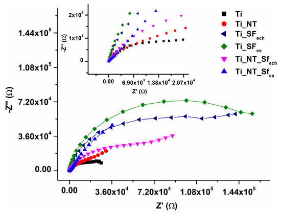
Figure 6.
Electrochemical impedance spectroscopy (EIS) data in terms of Nyquist diagram experimental data.
Depending on the surface modification three types of electric circuits were proposed (Figure 7) for EIS data fitting.
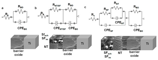
Figure 7.
Proposed equivalent electrical circuits used to fit the EIS data for: (a) untreated Ti; (b) Ti_NT, Ti_SFech, Ti_SFes; (c) Ti_NT_SFech, Ti_NT_SFes.
A first circuit was proposed for untreated titanium (Figure 7a). The related circuit comprises a resistance Rs—the resistance of the solution. For TiO2-barrier native oxide layer (BO) spontaneously formed in contact with the air or electrolyte solutions, a RBO resistance in parallel with CPEBO (constant phase element) were added.
For samples that have another deposited film over Ti, new elements were added to the proposed circuit: a resistance noted with RNT for the Ti_NT sample or the RSF resistance for the Ti_SFech and Ti_SFes samples in parallel with a CPENT for nanotube film, respectively CPESF corresponding to the fibroin film (Figure 7b).
In the case of NT_SF hybrid coatings, the circuit became even more complex by supplementary adding an RSF resistance and a CPESF corresponding to the fibrous film (Figure 7c).
The electrochemical parameters obtained after data fitting are presented in Table 2.
Table 2.
Electrochemical parameters resulted from the fitting of EIS spectra.
In all cases, the RBO resistance values varied between tens of kΩ for samples Ti and Ti_NT, hundreds of kΩ for Ti coated with fibroin films and thousands of kΩ for Ti coated with hybrid films.
CPE was characterized by Y—the numerical value of admittance and N—an empirical constant having values between 0 and 1 (when N = 1 CPE behaved as a pure capacitor, and when N = 0, the CPE behaved as a pure resistor). In the case of Ti, the value of NBO = 0.859, which indicated a pseudo-capacitive behaviour. For the samples with monolayer (NT or SFech/SFes) the values for the NBO constant are also in the pseudo-capacitive domain. On contrary, samples with hybrid films had NBO around 0.48 indicating an increase in resistivity probably due to the reinforcement of the barrier oxide layer during the deposition of fibroin.
The value of RNT resistance for TiO2 nanotubes is 12.7 kΩ. In Ti_NT_SFech sample this resistance increased up to 69 kΩ, while for Ti_NT_SFes it became significantly higher, 278 kΩ. Since all samples were anodized under the same conditions, these differences can be attributed to the interactions that occurred between TiO2 nanostructures and fibroin. The NNT values indicated a pseudo-capacitive character for Ti_NT (0.808) and Ti_NT_SFes (0.815). For Ti_NT_SFech the lower value of NNT (0.499) ccould be associated with a pseudo-resistive behaviour probably due to the electrochemically deposition of fibroin between and within the TiO2 nanotubes evidenced in SEM images.
Regarding the third resistance, the RSF, introduced for the fibroin film, was in the order of tens of kΩ for Ti_SFech (64.3 kΩ) and Ti_SFes (95.2 kΩ). In the case of hybrid film samples (Ti_NT_SFech and Ti_NT_SFes), this resistance was one order of magnitude lower, probably due the porous structure of the fibroin film. The values of the NSF constants were in the pseudo-capacitive range for all four samples mentioned above.
The data obtained from EIS reveals that the electrochemical stability of all modified surfaces was improved comparing with unmodified titanium. This stability is strongly influenced by the barrier oxide layer and the nanostructured oxide layer in the form of TiO2 nanotubes and is less influenced by fibroin film.
Tafel Analysis
From the Tafel representations (Figure 8), the corrosion parameters corrosion potential (Ecorr), corrosion current density (icorr), corrosion current (Icorr) and corrosion rate Vcorr (Table 3) were obtained for all modified surface and untreated Ti samples.
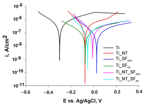
Figure 8.
Tafel Diagram for samples analysed in Ringer’s solution.
Table 3.
Corrosion parameters specific for nanostructured and functionalized fibroin samples.
It is obvious that the surface modification with titanium oxide and/or fibroin led to a shifting in corrosion potential from −300 mV for Ti to more electropositive values, up to 26.28 mV for Ti_SFech, indicating an improvement in Ti surface stability after the coating deposition.
The same aspect was also indicated by lower values of corrosion currents for coated samples compared to untreated Ti. Thus, the value of the corrosion current decreased from 6.30 × 10⁻⁷ A for Ti, to 3 to 4 times lower values for nanostructured samples. This is firstly due to the compact oxide layer consolidation during titanium anodization.
In addition, the obtained values allow a comparison between the stability of the samples, according to the fibroin deposition method. It was found that in the absence of titanium oxide nanotubes, the sample with the highest stability was Ti_SFes (coverd with a denser and thicker fibroin film) compared to Ti_SFech. For samples containing NT and fibroin, the situation was reversed. Ti_NT_SFech sample presented a lower corrosion resistance compared with Ti_NT_SFes probably due to the consolidation of barrier oxide layer during the anodic deposition of fibroin, as can be observed in Table 2.
On the other hand, the higher stability of Ti_NT_SFech compared to Ti_SFech can be explained by the fact that the presence of NT increased the surface area and the number of fibroin anchor sites resulting a better structured film. The presence of NT did not have such influence in terms of corrosion rate for the pair Ti_SFes and Ti_NT_SFes.
All coatings contributed to an improved corrosion stability comparing with unmodified Ti.
3.3. CeO2 Incorporation into Fibroin Film
3.3.1. EDX Analysis
The ability of fibroin coating to incorporate an antibacterial compound during deposition was studied. EDX analysis of obtained samples was performed and the atomic percent for component elements of the two samples, Ti_NT_SFes_CeO2 and Ti_NT_SFech_CeO2, are presented in Table 4.
Table 4.
Atomic percent for component elements for the analysed samples.
These results evidenced firstly the presence of fibroin through specific elements (C and N) from the protein structure. The atomic percentage of C and N was 52.53% and 17.04% for the films deposited by electrospun and respectively 27.53% and 9.64% for the electrochemical deposited fibroin. This is consistent with that was observed in the SEM images: a thicker fibroin film deposited by electrospun method (Figure 3) compared to the electrochemical method (Figure 2).
The atomic percentage of Ti was higher for Ti_NT_SFech_CeO2 (22.52%) than for Ti_NT_SFes_CeO2 (2.85%), thus confirming a lower amount of fibroin in case of electrochemical deposition.
The percentage of cerium was higher in the electrospun film 7.54% compared to that obtained by electrochemical deposition, 2.49%. This may be due to the electrospinning experimental conditions that lead to the deposition of a larger amount of fibroin. Along with this, a larger amount of cerium oxide was embedded in the fibrous film deposited on the titanium substrate. Another explanation should be given by the fact that CeO2 had a total positive charge, as was already discussed in a previous work [51]. During the electrochemical deposition, titanium represented the anode (the positive electrode) and was not able to attract a higher quantity of a positive polarized CeO2 nanoparticles.
Both electrochemical and electrospinning fibroin deposition methods allowed CeO2 antibacterial agent incorporation.
3.3.2. Antibacterial Effect
To determine the in vitro effect of the antibacterial action of the test samples, the pathogenic bacterium Escherichia coli ATCC 8738 was used. It was chosen for this study to be one of the most common infectious agents for implants. Moreover, in order to highlight the effectiveness in antibacterial effect of embedded cerium oxide nanoparticles in fibroin films deposited on titanium substrates two quantitative tests were performed.
Determination of Colony Forming Units (CFU)
By this method, colony-forming units (CFU) were counted for the test samples, and the antibacterial effects were calculated using Equation (1). The values obtained for (CFU) and Z (susceptibility constant) are shown in Table 5.
Table 5.
Values obtained for colony-forming units, antibacterial effects and susceptibility constants.
In the case of samples that did not have cerium oxide nanoparticles, a more pronounced development of Escherichia coli bacteria (Figure 9) was observed, the values obtained for samples Ti_NT_SFech and Ti_NT_SFes being greater than 550 CFU/mL, compared to sample Ti_NT_SFes_CeO2 where the value obtained was 113 CFU/mL.
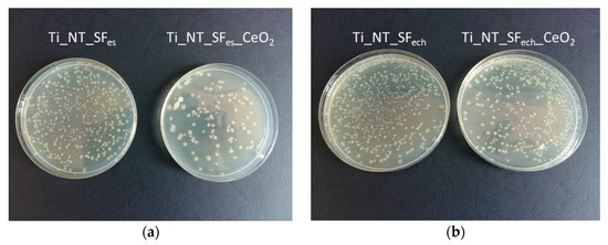
Figure 9.
Escherichia coli in Petri plates for determining colony-forming units: (a) for Ti_NT_SFes and Ti_NT_SFes_CeO2; (b) Ti_NT_SFech and Ti_NT_SFech_CeO2.
Susceptibility constants (Z) for samples containing cerium oxide at a concentration of 500 μg/mL were determined using Equation (2). Nanoparticle susceptibility constants were determined and used to evaluate the antibacterial action of cerium oxide nanoparticles against Escherichia coli.
The highest value of the susceptibility constant was obtained for the sample Ti_NT_SFes_CeO2 (Z = 0.0031 mL/μg), followed by the value obtained for the sample Ti_NT_SFech_CeO2 (Z = 0.0009 mL/μg), the antibacterial effects for these samples being of 79% and 37%, respectively. For samples that did not show CeO2 nanoparticles there was no antibacterial effect.
Determination of Inhibition Degree
The inhibition degree (I%) calculation was performed using Equation (3). The values obtained for samples containing cerium oxide nanoparticles, Ti_NT_SFes_CeO2 and Ti_NT_SFech_CeO2, were 76% and 32% respectively (Figure 10). The values obtained for optical densities can be seen in Table 6.
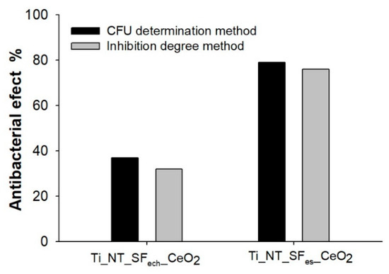
Figure 10.
Antibacterial effect obtained with inhibition degree method.
Table 6.
The values obtained for optical densities and degree of inhibition.
The results were similar to those obtained for the antibacterial effect calculated using the determination of colony forming units method (CFU), where the antibacterial effect of the samples showing cerium oxide nanoparticles was 79% (Ti_NT_SFes_CeO2) and 37% respectively (Ti_NT_SFes_CeO2) (Figure 10).
For the samples that did not contain cerium oxide nanoparticles (Ti_NT_SFes and Ti_NT_SFech_CeO2), no antibacterial effect, this information being also suggested by CFU determination method.
The similarity of results confirms the antibacterial effect of film with CeO2 embedded nanoparticles.
The significant difference between the inhibition degree of the two types of samples can be attributed to the fact that, as observed in the EDX spectra, the fibroin film deposited by electrospun determined the inclusion of a larger amount of CeO2.
Starting from a natural and FDA approved biomaterial, a silk fibroin hybrid coating with an antibacterial and antioxidant agent-CeO2 [52,53], was obtained in this study. The new hybrid coating exhibits in vitro antibacterial effect opening the perspective of using as a promising bioactive coating for titanium implantable surfaces modification.
4. Conclusions
Titanium surface modification with fibroin extracted from Bombyx mori coccoons was successfully performed by electrospinning and electrochemical deposition. Different surface morphology was obtained depending of the deposition methods.
Electrochemical impedance spectroscopy and Tafel curves revealed an increase in corrosion stability after surface nanostructuration and fibroin deposition.
CeO2 nanoparticles were successfully incorporated during the deposition procedure showing the ability of fibroin film for antibacterial compounds incorporation.
The bioactivated silk-based coatings with its ability for a rapid integration within the surrounding bone tissues, antibacterial properties and corrosion stability, could be a promising bioactive surface modification for new applications in regenerative medicine.
Author Contributions
Conceptualization, S.P., C.U., C.D., and C.P.; methodology, S.P., C.U., C.D., and C.P.; validation, S.P., C.U., C.D., and C.P.; investigation, S.P., M.-E.Z., C.U., and C.D.; writing—original draft preparation, S.P.; writing—review and editing, S.P., C.P., C.D., and C.U.; visualization, S.P., C.U., C.D., and C.P.; supervision, C.P.; project administration, S.P. and C.P. All authors have read and agreed to the published version of the manuscript.
Funding
This research received no external funding.
Acknowledgments
The SEM analyses on FEI QUANTA 650 FEG were possible due to European Regional Development Fund through Competitiveness Operational Program 2014–2020, Priority axis 1, Project No. P_36_611, MySMIS code 107066, Innovative Technologies for Materials Quality Assurance in Health, Energy and Environmental-Center for Innovative Manufacturing Solutions of Smart Biomaterials and Biomedical Surfaces –INOVABIOMED.
Conflicts of Interest
The authors declare no conflict of interest.
References
- Vannoort, R. Titanium—The implant material of today. J. Mater. Sci. 1987, 22, 3801–3811. [Google Scholar] [CrossRef]
- Aranda, J.L.; Jimenez, M.F.; Rodriguez, M.; Varela, G. Tridimensional titanium-printed custom-made prosthesis for sternocostal reconstruction. Eur. J. Cardio-Thorac. 2015, 48, E92–E94. [Google Scholar] [CrossRef] [PubMed]
- Marenzi, G.; Impero, F.; Scherillo, F.; Sammartino, J.C.; Squillace, A.; Spagnuolo, G. Effect of different surface treatments on titanium dental implant micro-morphology. Materials 2019, 12, 733. [Google Scholar] [CrossRef] [PubMed]
- Demetrescu, I.; Ionita, D.; Pirvu, C.; Portan, D. Present and future trends in TiO2 nanotubes elaboration, characterization and potential applications. Mol. Cryst. Liq. Cryst. 2010, 521, 195–203. [Google Scholar] [CrossRef]
- Albu, A.M.; Draghicescu, W.; Munteanu, T.; Ion, R.; Mitran, V.; Cimpean, A.; Popescu, S.; Pirvu, C. Nitrodopamine vs. dopamine as an intermediate layer for bone regeneration applications. Mater. Sci. Eng. C 2019, 98, 461–471. [Google Scholar] [CrossRef]
- Ichim, L.; Pirvu, C.; Manole, C.C. Electrochemical stability of titanium-hydroxyapatite implantable material modified with Ceftriaxone. Int. J. Electrochem. Soc. 2018, 13, 11895–11905. [Google Scholar] [CrossRef]
- Ungureanu, C.; Dumitriu, C.; Popescu, S.; Enculescu, M.; Tofan, V.; Popescu, M.; Pirvu, C. Enhancing antimicrobial activity of TiO2/Ti by Torularhodin bioinspired surface modification. Bioelectrochemistry 2016, 107, 14–24. [Google Scholar] [CrossRef]
- Pirvu, C.; Mindroiu, M.; Craciunescu, O.; Constantin, D. The bioactivity and stability evaluation of the PPy/Ca-P hybrid films on titanium alloy implant. Mater. Plast. 2016, 53, 722–726. [Google Scholar]
- Dumitriu, C.; Ungureanu, C.; Popescu, S.; Tofan, V.; Popescu, M.; Pirvu, C. Ti surface modification with a natural antioxidant and antimicrobial agent. Surf. Coat. Technol. 2015, 276, 175–185. [Google Scholar] [CrossRef]
- Dumitriu, C.; Popescu, M.; Ungureanu, C.; Pirvu, C. Antibacterial efficiencies of TiO2 nanostructured layers prepared in organic viscous electrolytes. Appl. Surf. Sci. 2015, 341, 157–165. [Google Scholar] [CrossRef]
- Ungureanu, C.; Popescu, S.; Purcel, G.; Tofan, V.; Popescu, M.; Salageanu, A.; Pirvu, C. Improved antibacterial behavior of titanium surface with torularhodin-polypyrrole film. Mater. Sci. Eng. C 2014, 42, 726–733. [Google Scholar] [CrossRef] [PubMed]
- Popescu, S.; Ungureanu, C.; Albu, A.M.; Pirvu, C. Poly(dopamine) assisted deposition of adherent PPy film on Ti substrate. Prog. Org. Coat. 2014, 77, 1890–1900. [Google Scholar] [CrossRef]
- Manole, C.C.; Dinischiotu, A.; Nica, C.; Demetrescu, I.; Pirvu, C. Influence of electrospun TiO2 nanowires on corrosion resistance and cell response of Ti50Zr alloy. Mater. Corros. 2018, 69, 1609–1619. [Google Scholar] [CrossRef]
- Kulkarni, M.; Mazare, A.; Schmuki, P.; Iglič, A. Nanomedicine Chapter: Biomaterial Surface Modification of Titanium and Titanium Alloys for Medical Applications; One Central Press: London, UK, 2014; pp. 111–136. [Google Scholar]
- Ion, R.; Mazare, A.; Dumitriu, C.; Pirvu, C.; Schmuki, P.; Cimpean, A. Nanochannelar topography positively modulates osteoblast differentiation and inhibits osteoclastogenesis. Coatings 2018, 8, 294. [Google Scholar] [CrossRef]
- Popescu, S.; Manole, C.C.; Pirvu, C. Surface features changes and corrosion stability of titanium surfaces by suitable treatments. Rev. Chim. Buchar. 2013, 64, 796–802. [Google Scholar]
- Dumitriu, C.; Pirvu, C.; Demetrescu, I. The electrochemical formation and shielding mechanism of TiO2 nanotubes in organic electrolytes with different viscosity. J. Electrochem. Soc. 2013, 160, G55–G60. [Google Scholar] [CrossRef]
- Manole, C.C.; Pirvu, C.; Demetrescu, I. Evaluation of TiO2 nanotubes changes after ultrasonication treatment. Mol. Cryst. Liq. Cryst. 2010, 521, 84–92. [Google Scholar] [CrossRef]
- Demetrescu, I.; Pirvu, C.; Mitran, V. Effect of nano-topographical features of Ti/TiO2 electrode surface on cell response and electrochemical stability in artificial saliva. Bioelectrochemistry 2010, 79, 122–129. [Google Scholar] [CrossRef]
- Man, I.; Pirvu, C.; Demetrescu, I. Enhancing titanium stability in fusayama saliva using electrochemical elaboration of TiO2 nanotubes. Rev. Chim. Buchar. 2008, 59, 615–617. [Google Scholar] [CrossRef]
- Kowalski, D.; Kim, D.; Schmuki, P. TiO2 nanotubes, nanochannels and mesosponge: Self-organized formation and applications. Nano Today 2013, 8, 235–264. [Google Scholar] [CrossRef]
- Annabi, N.; Fathi, A.; Mithieux, S.M.; Weiss, A.S.; Dehghani, F. Fabrication of porous PCL/elastin composite scaffolds for tissue engineering applications. J. Supercrit. Fluids 2011, 59, 157–167. [Google Scholar] [CrossRef]
- Fathi, M.; Akbari, B.; Taheriazam, A. Antibiotics drug release controlling and osteoblast adhesion from titania nanotubes arrays using silk fibroin coating. Mater. Sci. Eng. C 2019, 103, 109743. [Google Scholar] [CrossRef] [PubMed]
- Sirivisoot, S.; Pareta, R.A.; Webster, T.J. A conductive nanostructured polymer electrodeposited on titanium as a controllable, local drug delivery platform. J. Biomed. Mater. Res. Part A 2011, 99, 586–597. [Google Scholar] [CrossRef] [PubMed]
- Yoshimoto, H.; Shin, Y.M.; Terai, H.; Vacanti, J.P. A Biodegradable nanofiber scaffold by electrospinning and its potential for bone tissue engineering. Biomaterials 2003, 24, 2077–2082. [Google Scholar] [CrossRef]
- Spasova, M.; Stoilova, O.; Manolova, N.; Rashkov, I.; Altankov, G. Preparation of PLLA/PEG nanofibers by electrospinning and potential applications. J. Bioact. Compat. Polym. 2007, 22, 62–76. [Google Scholar] [CrossRef]
- Jo, Y.; Yeo, J. Low molecular weight silk fibroin increases alkaline phosphatase and type I collagen expression in Mg63 cells. BMB Rep. 2010, 43, 52–56. [Google Scholar]
- Saha, S.; Pramanik, K.; Biswas, A. Silk fibroin coated TiO2 Nanotubes for improved osteogenic property of Ti6Al4V bone implants. Mater. Sci. Eng. C 2019, 105, 109982. [Google Scholar] [CrossRef]
- Rockwood, D.N.; Preda, R.C.; Yücel, T.; Wang, X.; Lovett, M.L.; Kaplan, D.L. Materials fabrication from Bombyx Mori silk fibroin. Nat. Protoc. 2011, 6, 1612–1631. [Google Scholar] [CrossRef]
- Yi, B.; Zhang, H.; Yu, Z.; Yuan, H.; Wang, X.; Zhang, Y. Fabrication of high performance silk fibroin fibers via stable jet electrospinning for potential use in anisotropic tissue regeneration. J. Mater. Chem. B 2018, 6, 3934–3945. [Google Scholar] [CrossRef]
- Wenk, E.; Merkle, H.P.; Meinel, L. Silk fibroin as a vehicle for drug delivery applications. J. Control. Release 2011, 150, 128–141. [Google Scholar] [CrossRef]
- Guo, Y.; Guan, J.; Peng, H.; Shu, X.; Chen, L.; Guo, H. Tightly adhered silk fibroin coatings on Ti6Al4V biometals for improved wettability and compatible mechanical properties. Mater. Des. 2019, 175, 107825. [Google Scholar] [CrossRef]
- Kiyoung, L.; Mazare, A.; Schmuki, P. One-dimensional titanium dioxide nanomaterials: Nanotubes. Chem. Rev. 2014, 114, 9385–9454. [Google Scholar]
- Burke, K.A.; Roberts, D.C.; Kaplan, D.L. Silk fibroin aqueous-based adhesives inspired by mussel adhesive proteins. Biomacromolecules 2016, 17, 237–245. [Google Scholar] [CrossRef] [PubMed]
- Melke, J.; Midha, S.; Ghosh, S.; Ito, K.; Hofmann, S. Silk fibroin as biomaterial for bone tissue engineering. Acta Biomater. 2016, 31, 1–16. [Google Scholar] [CrossRef]
- Kulkarni, A.A.; Pushalkar, S.; Zhao, M.; LeGeros, R.Z.; Zhang, Y.; Saxena, D. Antibacterial and bioactive coatings on titanium implant surfaces. J. Biomed. Mater. Res. A 2017, 105, 2218–2227. [Google Scholar] [CrossRef]
- Patianna, G.; Valente, N.A.; D’Addona, A.; Andreana, S. In-vitro evaluation of controlled-release 14% doxycycline gel for decontamination of machined and sandblasted acid-etched implants. J. Periodontol. 2018, 89, 325–330. [Google Scholar] [CrossRef]
- Bernardi, S.; Bianchi, S.; Tomei, A.R.; Continenza, M.A.; Macchiarelli, G. Microbiological and SEM-EDS evaluation of titanium surfaces exposed to periodontal gel: In vitro study. Materials 2019, 12, 1448. [Google Scholar] [CrossRef]
- Cremet, L.; Corvec, S.; Bemer, P.; Bret, L.; Lebrun, C.; Lesimple, B.; Miegeville, A.F.; Reynaud, A.; Lepelletier, D.; Caroff, N. Orthopaedic-implant infections by Escherichia Coli: Molecular and phenotypic analysis of the causative strains. J. Infect. 2012, 64, 169–175. [Google Scholar] [CrossRef]
- Sezonov, G.; Joseleau-Petit, D.; D’Ari, R. Escherichia Coli physiology in Luria-Bertani broth. J. Bacteriol. 2007, 189, 8746–8749. [Google Scholar] [CrossRef]
- Ansari, M.A.; Khan, H.M.; Khan, A.A.; Malik, A.; Sultan, A.; Shahid, M.; Shujatullah, F.; Azam, A. Evaluation of antibacterial activity of silver nanoparticles against MSSA and MRSA on isolates from skin Infections. Biol. Med. 2011, 3, 141–146. [Google Scholar]
- Rajendran, R.; Balakumar, C.; Kalaivani, J.; Sivakumar, R. Dyeability and antimicrobial properties of cotton fabrics finished with Punica Granatum extracts. J. Text. Appar. Technol. Manag. 2011, 7, 1–12. [Google Scholar]
- Grecu, M.; Novac, G.; Ionita, D.; Ungureanu, C. Incorporation of Tobramycin biomimetic in hydroxyapatite coating on CoCrMo alloy and its antimicrobial acitivity. Rev. Chim. Buchar. 2011, 62, 352–356. [Google Scholar]
- Beggs, C.B.; Noakes, C.J.; Sleigh, P.A.; Fletcher, L.A.; Kerr, K.G. Methodology for determining the susceptibility of airborne microorganisms to irradiation by an upper-room UVGI system. J. Aerosol Sci. 2006, 37, 885–902. [Google Scholar] [CrossRef]
- Jaiswal, S.; Duffy, B.; Jaiswal, A.K.; Stobie, N.; McHale, P. Enhancement of the antibacterial properties of silver nanoparticles using beta-cyclodextrin as a capping agent. Int. J. Antimicrob. Agents 2010, 36, 280–283. [Google Scholar] [CrossRef] [PubMed]
- Park, H.J.; Lee, J.S.; Lee, O.J.; Sheikh, F.A.; Moon, B.M.; Ju, H.W.; Kim, J.H.; Kim, D.K.; Park, C.H. Fabrication of microporous three-dimensional scaffolds from silk fibroin for tissue engineering. Macromol. Res. 2014, 22, 592–599. [Google Scholar] [CrossRef]
- Shen, G.T.; Hu, X.Y.; Guan, G.P.; Wang, L. Surface modification and characterisation of silk fibroin fabric produced by the layer-by-layer self-assembly of multilayer Alginate/regenerated silk fibroin. PLoS ONE 2015, 10, e0124811. [Google Scholar] [CrossRef] [PubMed]
- Catto, V.; Fare, S.; Cattaneo, I.; Figliuzzi, M.; Alessandrino, A.; Freddi, G.; Remuzzi, A.; Tanzi, M.C. Small diameter electrospun silk fibroin vascular grafts: Mechanical properties, in vitro biodegradability, and in vivo biocompatibility. Mater. Sci. Eng. C 2015, 54, 101–111. [Google Scholar] [CrossRef]
- Balaur, E.; Macak, J.M.; Tsuchiya, H.; Schmuki, P. Wetting behaviour of layers of TiO2 nanotubes with different diameters. J. Mater. Chem. 2005, 15, 4488–4491. [Google Scholar] [CrossRef]
- Shin, D.H.; Shokuhfar, T.; Choi, C.K.; Lee, S.H.; Friedrich, C. Wettability changes of TiO2 nanotube surfaces. Nanotechnology 2011, 22, 315704. [Google Scholar] [CrossRef]
- Popescu, S.; MMindroiu Cabuzu, D.; Pirvu, C. The roll of NaPSS surfactant on the Ceria nanoparticles embedding in polypyrrole films. J. Nanomater. 2016, 2016. [Google Scholar] [CrossRef]
- Xia, T.; Kovochich, M.; Liong, M.; Madler, L.; Gilbert, B.; Shi, H.B.; Yeh, J.I.; Zink, J.I.; Nel, A.E. Comparison of the mechanism of toxicity of zinc oxide and cerium oxide nanoparticles based on dissolution and oxidative stress properties. ACS Nano 2008, 2, 2121–2134. [Google Scholar] [CrossRef] [PubMed]
- Nelson, B.C.; Johnson, M.E.; Walker, M.L.; Riley, K.R.; Sims, C.M. Antioxidant cerium oxide nanoparticles in biology and medicine. Antioxidants 2016, 5, 15. [Google Scholar] [CrossRef] [PubMed]
© 2020 by the authors. Licensee MDPI, Basel, Switzerland. This article is an open access article distributed under the terms and conditions of the Creative Commons Attribution (CC BY) license (http://creativecommons.org/licenses/by/4.0/).