Article

Composite of PLA Nanofiber and Hexadecyl Trimethyl-Ammonium Chloride-Modified Montmorillonite Clay: Fabrication and Morphology

1
Key Laboratory of Eco Textiles, Jiangnan University, Wuxi 212242, Jiangsu, China
2
Department of Textile Processing, Faculty of Engineering and Technology, National Textile University, Faisalabad 37610, Pakistan
3
Department of Textile Engineering, Faculty of Engineering and Architecture, Balochistan University of Information Technology, Engineering and Management Sciences, Quetta 87500, Pakistan
4
College of Textiles, Donghua University, Shanghai 201620, China
*
Author to whom correspondence should be addressed.
Coatings 2020, 10(5), 484; https://doi.org/10.3390/coatings10050484
Submission received: 10 April 2020 / Revised: 10 May 2020 / Accepted: 13 May 2020 / Published: 18 May 2020

Abstract

:
Our research aim is to develop a new composite material via electrospinning and dip coating methodology. Among bioabsorbable polymers, Polylactic acid (PLA) is viewed as a suitable base material for biomedical usages such as drug delivery and wound dressing. Additionally, these bioabsorbable materials can be used for filtration applications in terms of antibacterial activity the integration of hexadecyl trimethyl ammonium chloride-modified montmorillonite (CTAC-MMT) into PLA fibers would improve mechanical and absorption properties of the PLA fibers. This research aimed to investigated a new method of combining electrospun PLA with dip coating of CTAC-MMT solution. Precisely, electrospun PLA nanofibers were treated with methanol and dipped in a CTAC-MMT suspension. The resultant layer composite of PLA nanofibers and CTAC-MMT was then characterized by elemental analysis. For material characterization and morphological structure analysis, we performed FTIR, SEM-EDS, XPS, DSC, and X-ray diffraction. Through mechanical testing and contact angle measurements, it was found that CTAC-MMT shows a slight improvement in mechanical and absorption properties. Results of characterization techniques have shown that CTAC-MMT can be used as a good filler for composites processed through the dip-coating method. Moreover, results also showed that the diameter of microfibers is affected by concentrations of PLA.

1. Introduction

In recent years, nanomaterials have shown substantial potential in diverse practical applications such as filtration [1,2] systems, chemical or optical sensors [3,4], scaffolds for tissue regeneration including drug delivery systems [5,6], and wound healing [7,8].
In previous studies, many fiber preparation methods have been used; for example, self-assembly, phase-separation, electrospinning, and others [9,10,11,12]. Many key factors play a very important role to decide to choose techniques or methods for the production of polymer fibers. These key factors include simplicity and economic nature of the setup, continuous process for the production of polymer fibers, optimization of operational parameters, and diversity [13].
There are stages, which are dissolution, gelation extraction in phase separation technique by applying a different kind of solvent to attain nanostructure films, but in phase-separation, the mechanism of the process is quite long as compared to other techniques. The self-assembly technique has the same drawback as phase-separation which is more time-consuming. [14,15]. The advantage of electrospinning is to produce nanofibers from many types of polymers (natural, synthetic, semi-synthetic, etc.) in a very short time. The other benefits of electrospinning are the nanofiber’s unique structure such as the small pore size, high surface area to volume ratio, and high porosity [16,17,18]. The functioning process of electrospinning mainly depends on the use of an electrostatic force [19,20], among a metallic needle-syringe having the charged jet of a polymeric solution and metal collector drum for the deposition of nanofibers. When the electrostatic field overcomes the surface tension of the solution, a polymeric jet is generated from the surface of the droplet and travels towards the collector. Between the needle and the collector, the solvent evaporates from the jet and, subsequently, nanofibers can be collected [16]. The morphology and other structural parameters of the resultant nanofibers depend on many factors. These factors could be categorized into three groups: solution properties, process parameters, and ambient conditions [11,16,21,22,23].
Recently, polylactide or poly (lactic acid) (PLA) has been seen as one of the most benefitted polymers due to its versatility, eco-friendliness, biodegradability, and biocompatibility when compared with other materials. PLA is not available in nature but can be industrially manufactured by polymerization of lactic acid, which we can get from starch renewable resources. Generally, PLA has vast applications in the area of bio-medicine, premium food packaging, drug delivery, etc. [24,25]. For specific and targeted applications, PLA requires significant improvements in physical–chemical properties. In the last ten years, researchers used nanofiller incorporation with PLA and with other polymers to improve their mechanical and thermal properties along with other properties [2]. The PLA/clay nanocomposites and the effect of clay on PLA nanofibers have been discussed in the literature for biomedical and food packaging applications [26,27].
In clays, montmorillonite (MMT) has been widely used as a nanofiller for polymers to enhance the physical and chemical properties of the material for end-use. It is a water-absorbent and inorganic clay, which mainly has hydrated Na+ or K+ ions. Polyethylene oxide or polyvinyl alcohol polymers determined as hydrophilic polymers can be easily bonded with silicate layers of clays [28,29]. To render layered silicates with hydrophobic polymer matrices, it is very important to change the generally hydrophilic silicate surface to an organophilic state, preparing the polymer chains into inorganic galleries more efficiently by applying ion-exchange reactions with cationic surface ions. This development creates widening among the clay galleries, because of the bigger molecules added between the layers. The aforementioned process of reactions also transforms the clay from the hydrophilic state to the hydrophobic state, making it more suitable as an organic matrix. Furthermore, the alkylammonium or alkyl phosphonium cations can deliver functional groups that can react with the polymer matrix, or under certain conditions activate the polymerization of monomers to significantly improve the bonding between the inorganic and the polymer matrix [30]. Research work on modified MMT blending with various polymers like polycaprolactone (PCL), polyethylene (PE), and polylactic acid (PLA) has been investigated in the past few years [31,32,33]. These research investigation reports highlighted the importance of spinning capabilities of fibers or films of polymer nanocomposite. It is well-known that only some polymers display significant fiber-forming potential. However, it is likely that the physicochemical and antimicrobial properties of polymer nanocomposite can be determined by analyzing nanofiber morphologies. Polypropylene bonding with CU-MMT nanocomposites with remarkable antimicrobial properties has been studied [34]. Polymer blending with nano-clay composites can be experimentally fabricated via four different approaches: melt intercalation, solution intercalation, in situ intercalative polymerizations, in situ direct synthesis, and solution intercalation. These techniques have their advantages and disadvantages and as research has progressed, researchers have shown interest in using a simple, cost-effective, and ecofriendly technique [35,36,37]. Ogata et al. studied the structure and thermal/mechanical properties of poly(l-lactide) blending with clay through a solvent-cast blended method. They concluded that clay was in the form of tactoids due to these silicate layers not being individually well dispersed in PLLA–clay blends by using this method [38]. Ray et al. used the melt-extrusion technique to fabricate polylactic acid (PLA)/layered silicate nanocomposites. It has been observed that PLA/MMT nanocomposites can show significant improvement in mechanical properties of the material with the addition of MMT [39]. Pluta et al. studied the structure, dielectric, viscoelastic, and thermal properties of PLA/MMT nanocomposites by using a melt blending technique [40]. In our previous study, we fabricated and characterized electrospun films from polylactic acid and CTAC-MMT clay [41]. Dip coating is a comparatively better technique to develop a nanocomposite where the substrate is absorbed in the solution for the productive development of the nanocomposite material. The advantages of dip coating are cost-effectiveness and that layer thickness can be smoothly transformed [42]. While in terms of electrospinning, sometimes a problem of solution viscosity is observed, because of which, it takes more time and may have a high cost. On the other hand, sometimes, solution bonding issues arise during the making of solutions. Due to this, we firstly used electrospinning to make nanofibers as a base material and then a dip-coating method was used for better and qualitative results [43]. Our current study suggests a method to prepare new PLA/CTAC modified montmorillonite composites by using an uncomplicated, eco-friendly, and economical technique. The final composite had an interesting morphological structure, in which the PLA nanofibers and CTAC-MMT were bonded uniquely. To the best of our knowledge, in this research work, we used the dip-coating method for the first time to develop electrospun PLA/CTAC-MMT composites, which were then characterized using SEM-Eds, FTIR, XRD, XPS, and differential scanning calorimeter techniques. We have also performed mechanical and contact angle tests for the composites prepared by the dip-coating method.

2. Materials and Method

2.1. Materials

Polylactic acid (PLA) (with L-lactide 88% by weight and Tg of 55–60 °C) was obtained from (E.sun Industry Shenzhen, Shenzhen, China). CTAC-MMT was purchased from (Hongkai Mining Industry, Shenzhen, China). Dichloromethane (DCM), tetrahydrofuran (THF), and dimethylformamide (DMF) were used as a solvent and obtained form (Aladin reagents, Shanghai, China). Properties of these solvents are displayed in Table 1 which played an important role in the selection of solvent as the PLA dissolving parameters are 10 cal1/2 cm−3/2 [39].

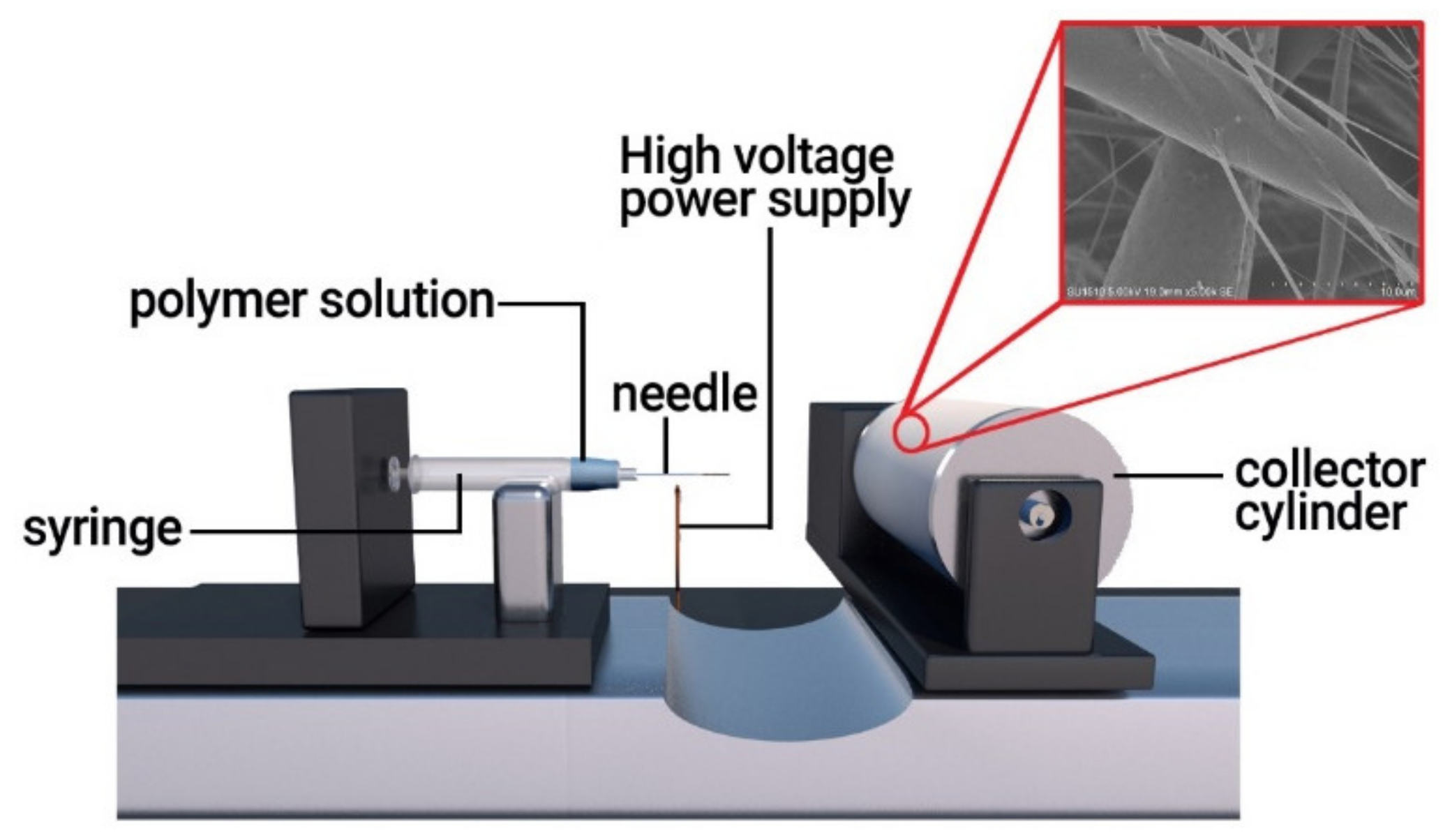
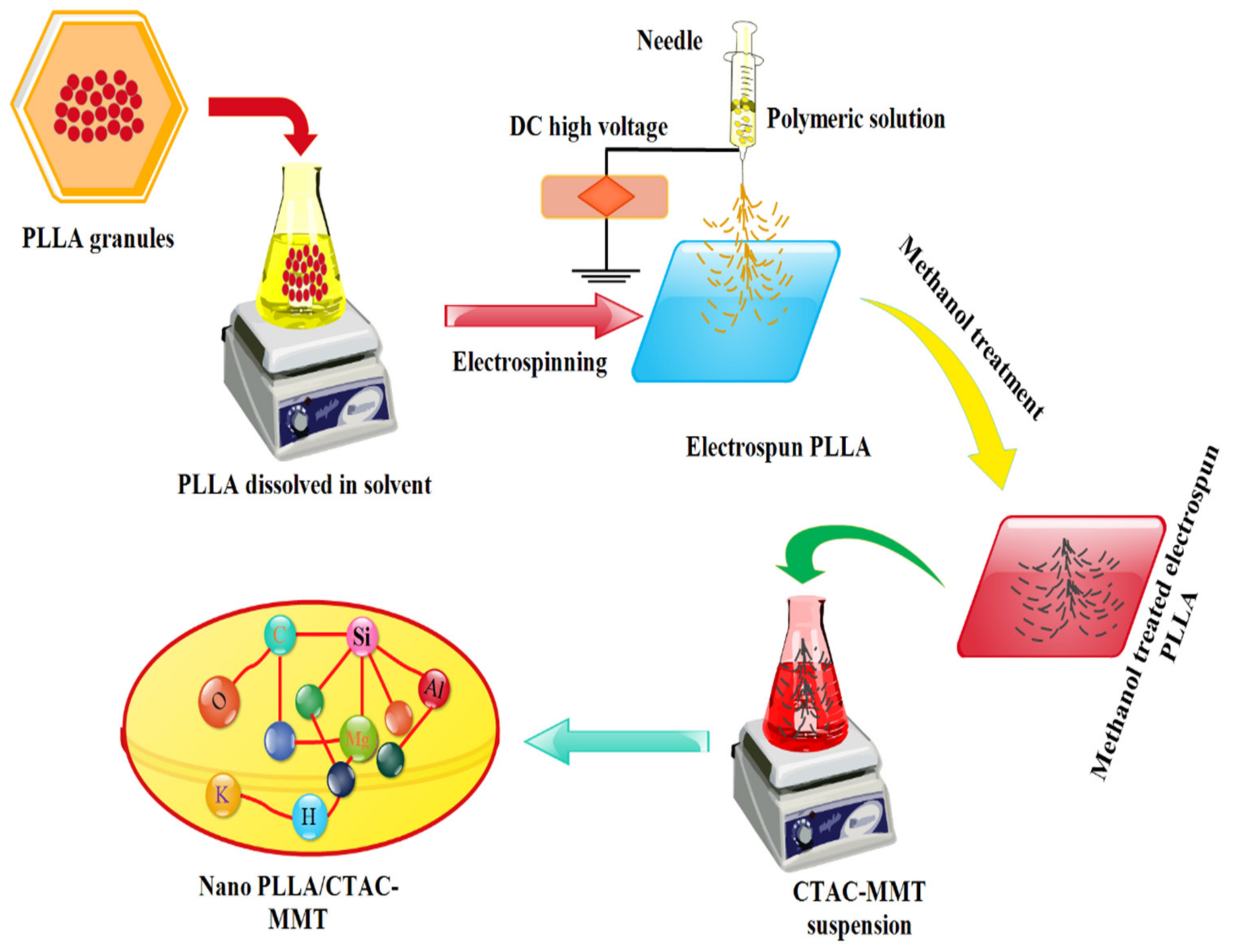
2.2. Preparation of PLA Nanofiber

The 10% w/v polymer concentration electrospinning solutions were prepared by dissolving PLA 50/50 v/v ratio. The pre-weighed amount of PLA was added in a glass bottle and magnetically stirred for 4 h at 25 °C temperature. PLA was dissolved to obtain solutions with concentrations 10, 12.5, and 15% w/v.
An electrospinning apparatus (model, CPS-60K02VIT; CHUNGPA EMT Co., Seoul, Korea) was used at 25 °C temperature. The PLA/DCM solution was added into a 5 mL syringe, which was connected with the high voltage power supply [36] to prepare the PLA nanofibers (Figure 1) in house laboratory of Jiangnan University, Wuxi, China. An electric voltage (20 to 30 kV) was supplied via a needle to droplets of PLA/DCM: DFM: THF solution. At 15 cm from the syringe tip, the electrospun nanofibers were collected on aluminum foil.

2.3. Synthesis of PLA/CTAC-MMT Composites

Figure 2 clearly illustrates the preparation process for the PLA/CTAC-MMT composite. For further explanation, the PLA nanofibers composite was immersed in absolute methanol at a temperature of 25 ± 0.1 °C for 15 min, then excess methanol was removed and the same was dried in a conditioned room at a temperature of 25 ± 0.3 °C until a constant weight was reached (WAKO Ltd., Tokyo, Japan). Three solutions of 0.1%, 0.5%, and 1.0% by weight aqueous solution of MMT were prepared in three separate conical flasks. Then, for dip coating, a portion of dried PLA nanofibers was accurately weighed and dipped in MMT solution flasks separately at 25 °C for 12 h. After that, the sample was dried until a constant weight at room temperature was obtained. The resulting products were named PLA/CTAC-MMT1, PLA/CTAC-MMT2, and PLA/CTAC-MMT3 nanocomposites with 0.1%, 0.5%, and 1.0% MMT, respectively.

2.4. Characterization

Surface morphologies of the PLA and PLA/CTAC-MMT nanocomposites were examined by (S4800 SEM Hitachi, Tokyo, Japan). Fiber diameter was measured by Image J software. A Nicolet Nexus 470 FT-IR spectrometer was used to examine different functional groups on the nanofibers, the FT-IR spectra were conducted in the wavelength range of 4000–450 cm−1.
X-ray spectroscopy was conducted using a Kratos XSAM800 XPS system with charge neutralizer and Kα source. An X-ray diffractometer (XRD, Bruker D8, 40 kV, 40 mA, Beijing, China) was used for the detection of a crystalline region with Cu Kα radiation (wavelength λ = 1.54 Å) at a scanning speed of 0.02° s–1 with a 2θ range of 10°–90°.
Transition temperatures and latent-heat capacity of PLA, CTACMMT and PLA/CTAC-MMT composites were evaluated with a differential scanning calorimetry technique by using this machine (DSC, Q 200) in an inert atmosphere of N2, and 10–400 °C temperature range at a heating/cooling rate of 5 °C min–1.

2.5. Mechanical Performance

The tensile strength of all samples was tested by a tensile tester (Instron, model 5566). All the samples were conditioned at room temperature and 45% relative humidity for 24 h. Samples were cut into sizes of 40 mm × 5 mm and tested at the rate of 10 mm/min at ambient temperature and 45% humidity. The tensile strength and elongation at break were calculated with an average of five-sample values. The thickness was adjusted with a micrometer caliper [40].

2.6. Contact Angle

Data Physics Instruments Gmbh (Filderstadt, Germany) was used to measure contact angles at 45% humidity and standard room temperature. A small 5 μL water droplet was dropped onto the samples one by one and the time to absorb and the angle at the nanofibrils sheet were measured. Five consecutive readings were observed for each sample to overcome chances of error.

3. Results and Discussion

3.1. Concentration Effect of PLA/DCM:THF:DFM Solution and Application

The findings reveal that as the solution concentration increased, the viscosity of the solution also increased. Surface tension and viscosity were the parameters to describe the fiber morphology with increasing concentration [16,41].
As the polymer concentration increased, the chain entanglements increased, and solution viscosity also increased, which increased in the viscoelastic force; the coulombic stretching forces are counterbalanced, therefore, resulting in nanofibers with low beads. This is also shown in Figure 3a–d [41,42,43]. The CTAC-MMT suspension was coated on a sheet of electrospun PLA nanofibers and the resultant composite SEM is shown in Figure 3e, which confirms that the obtained membranes containing PLA nanofibers were seemingly bonded to the MMT.
In the electrospinning process, all parameters including needle distance, solvent concentration, and polymer concentration outcome on the diameter of nanofibers (Table 2) were set according to requirements; the effect of the voltage parameter on the diameter of nanofibers has been previously discussed [44,45]. The ion movement charged the surface of the polymer solution. The surface tension was overcome with high electric force and a stable jet emerged from the needle. Therefore, it is necessary to manage the voltage to determine the cone shape of a polymer.
Figure 4 illustrates the fibers’ average diameter of PLA fibers collected at different concentrations. The ratio of solvents in the order of DCM:DMF:THF was set at 80:20:20, respectively, while the receiving distance was 15 cm with 1 mL/h rate. The first jet was initiated at a voltage of 8 kV. It was readjusted at 12 kV as it was not stable below this voltage (Taylor cone). By increasing the voltage over 20 kV, the Taylor cone shape was disturbed and became asymmetrical, and so the fiber diameter increased and became irregular as shown in Figure 4c. Figure 4a,b shows that both fiber diameters were relatively small at voltages of 12 and 15 kV. Further, the diameter deviation was the smallest at the voltage of 15 kV, which means that the diameter of a uniform fiber was formed as shown in Figure 4b.

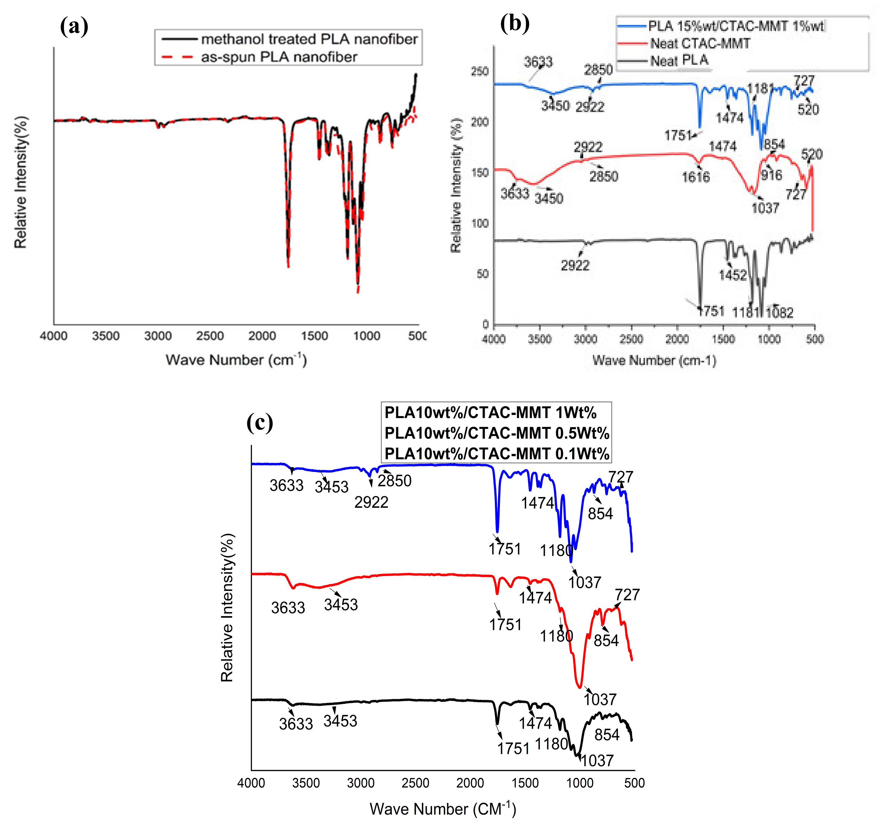
3.2. FT-IR Spectroscopy

By using methanol treatment used in the literature, a change was observed from a random coil structure β sheet conformation in the amide I and II regions. The spun PLA nanofiber had an absorption peak in between 1600 and 1700 cm−1 associated with amide-I, while the amide-II peak is in the range of 1500–1600 cm−1 [46]. Fourier-transfer infrared spectrometer (FT-IR, Nicolet Magna-IR 750) was employed to determine the molecular formulation of the PLA nanofibers (Figure 5a) [47].
The FTIR of the neat CTAC-MMT shows a strong peak at 3460 cm−1 associated with the characteristic O–H stretching vibration of the adsorbed water in the CTAC-MMT layer. The bending vibrations of O–H were observed at 1650 cm−1. The FTIR spectrum of neat CTAC-MMT shows the typical 3630 and 1040 cm−1 stretching vibrations of the O–H and Si–O functional groups. After the dip-coating method, PLA/CTAC-MMT clay composites appear as shown in Figure 5c, in addition to some new peaks at 2922–2988 and 2850 cm−1 belonging to –CH asymmetric stretching vibration and bending vibrations, respectively. Further, there was a new peak at 1474 cm−1, which corresponded to the –CH2 bending vibrations, and there was a new peak at 1474 cm−1, which corresponded to the –CH2 bending vibrations; this further supports the existence of alkylammonium ions between the silicate layers. The bands of the N–H amine groups of PLA/CTAC-MMT nanocomposites were assigned at 1470 cm−1 (Figure 5b) [48].
FTIR provided further evidence for the presence of MMT in new composite PLA/CTAC-MMT nanofibers (Figure 5). In the control CTAC-MMT, the absorption peak observed at 3633 cm−1 was attributed to the stretching vibration of Al–Al–OH groups in the octahedral layer. Si–O stretching vibrations were observed as the peak at 1037 cm−1. The O–H bending vibrations in dioctahedral 2:1 layer silicates were located at 916, 854 cm−1, and tetrahedral bending modes were also seen at 500 cm−1 for Si–O–Al. (Figure 5b) [49]. The PLA/CTAC-MMT nanocomposite nanofibers both displayed a broad absorption band at 3600–3100 cm−1 due to the –OH group. The peaks at 2998 and 2948 cm−1 can be attributed to the stretch vibration mode of –CH3 and –CH2– groups. The peaks located at 1725–1751 cm−1 are ascribed to C=O stretching vibration, representing the existence of –C=O– groups in PLA/CTAC-MMT nanocomposite nanofibers [50]. Compared with neat PLA nanofibers PLA/CTAC-MMT nanocomposite nanofibers showed two new peaks at 500–520 cm−1, signifying the existence of CTAC-MMT within the PLA membranes (Figure 5b) [51]. The peaks located at 2994 and 1751 cm−1 of PLA were allotted to the stretching vibration of –CH2 and vibration of –C=O bonds, correspondingly. The spectrum of PLA/CTAC-MMT nanocomposites shows the peaks at 2997 and 2944 cm−1 are due to the C–H stretching. The peak for C=O bending is observed at 1751 cm−1. The peak for C–O bending is at 1180 cm−1 (Figure 5c) [16,52]. In the area wavelengths of 1690–1760 cm−1, there is a C=O bond which is a carbonyl group corresponding to a wavelength of 1759 cm−1. Between the wavelengths of 1340 and 1470 cm−1, the CH3 bonds are revealed at the wavelengths of 1457 and 1050–1300 cm−1 (Figure 5c) [53].

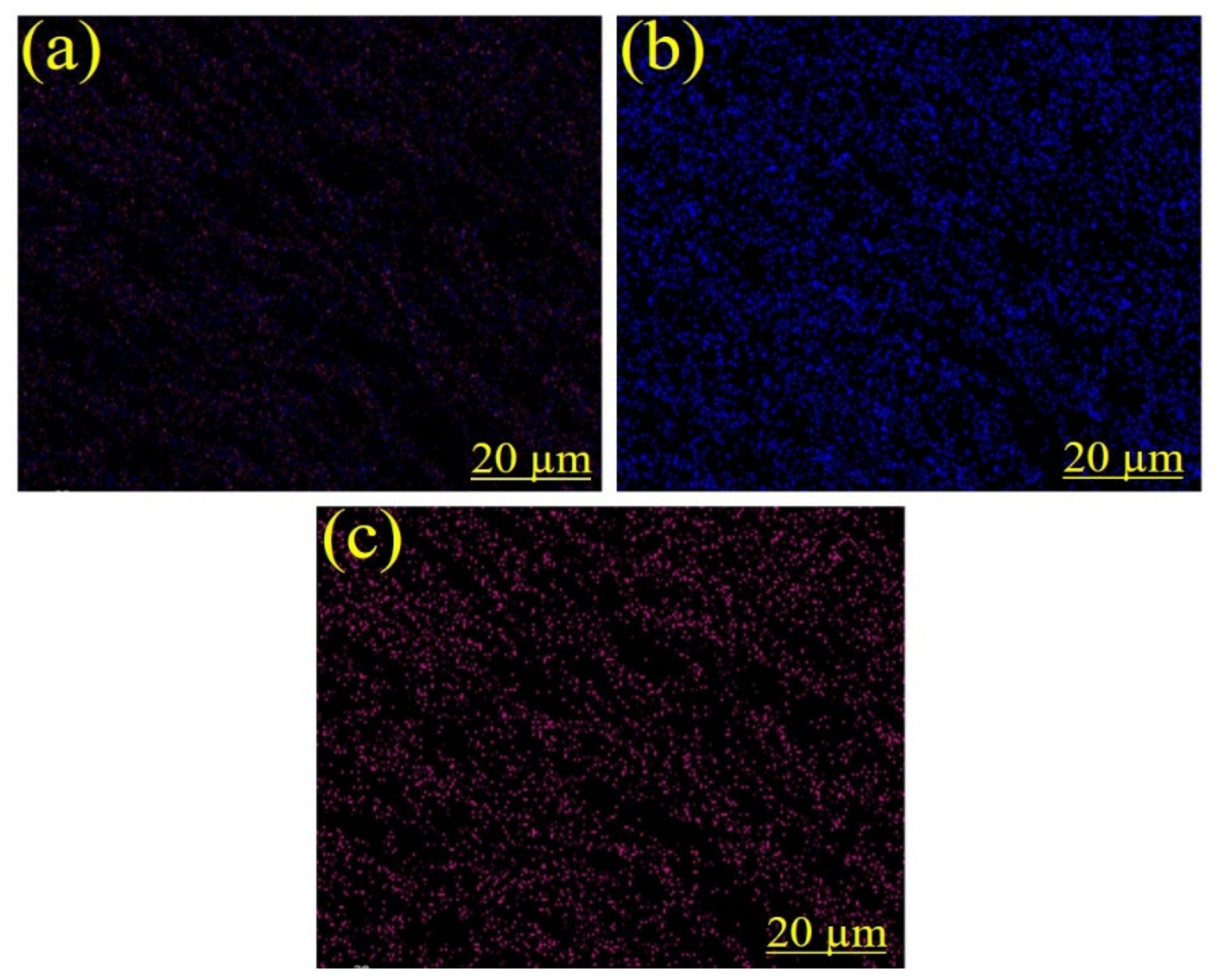
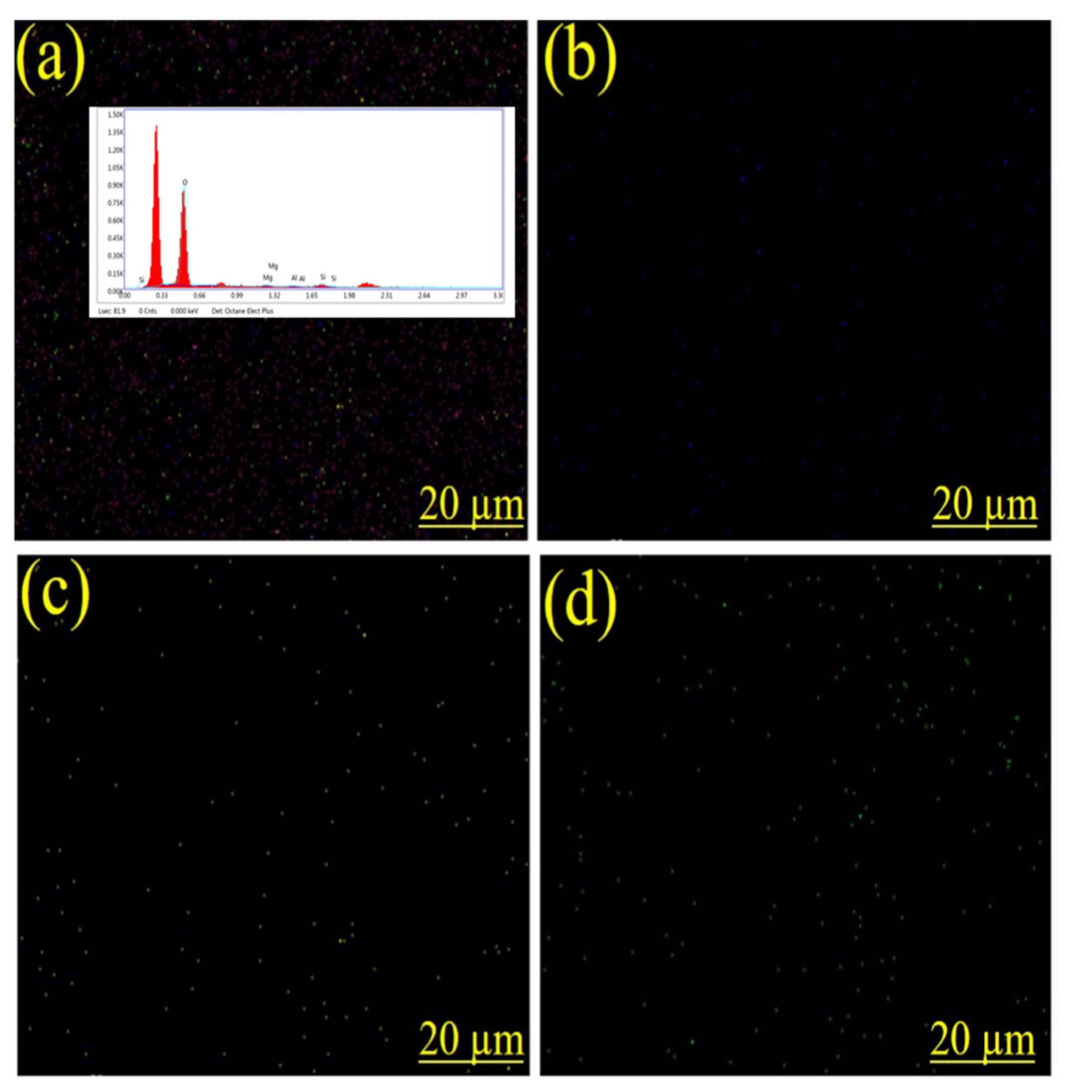
3.3. Energy Dispersive X-ray (EDX) Spectroscopy Analysis

EDX was performed to check the chemical properties like elemental presence in PLA and PLA/CTAC-MMT as shown in Figure 6. The carbon and oxygen are present in abundance in the PLA as shown in (Figure 6b). The thermal degradation significantly decreased the carbon content from PLA [54].
PLA/CTAC-MMT had a significantly higher amount of oxygen, magnesium, aluminum, and silicon representing the presence of the nano-clay in the material as also mentioned in the literature [54,55], thus it can be concluded that the product is mainly composed of nano-clay byproduct as clearly shown in Figure 6 and Figure 7.

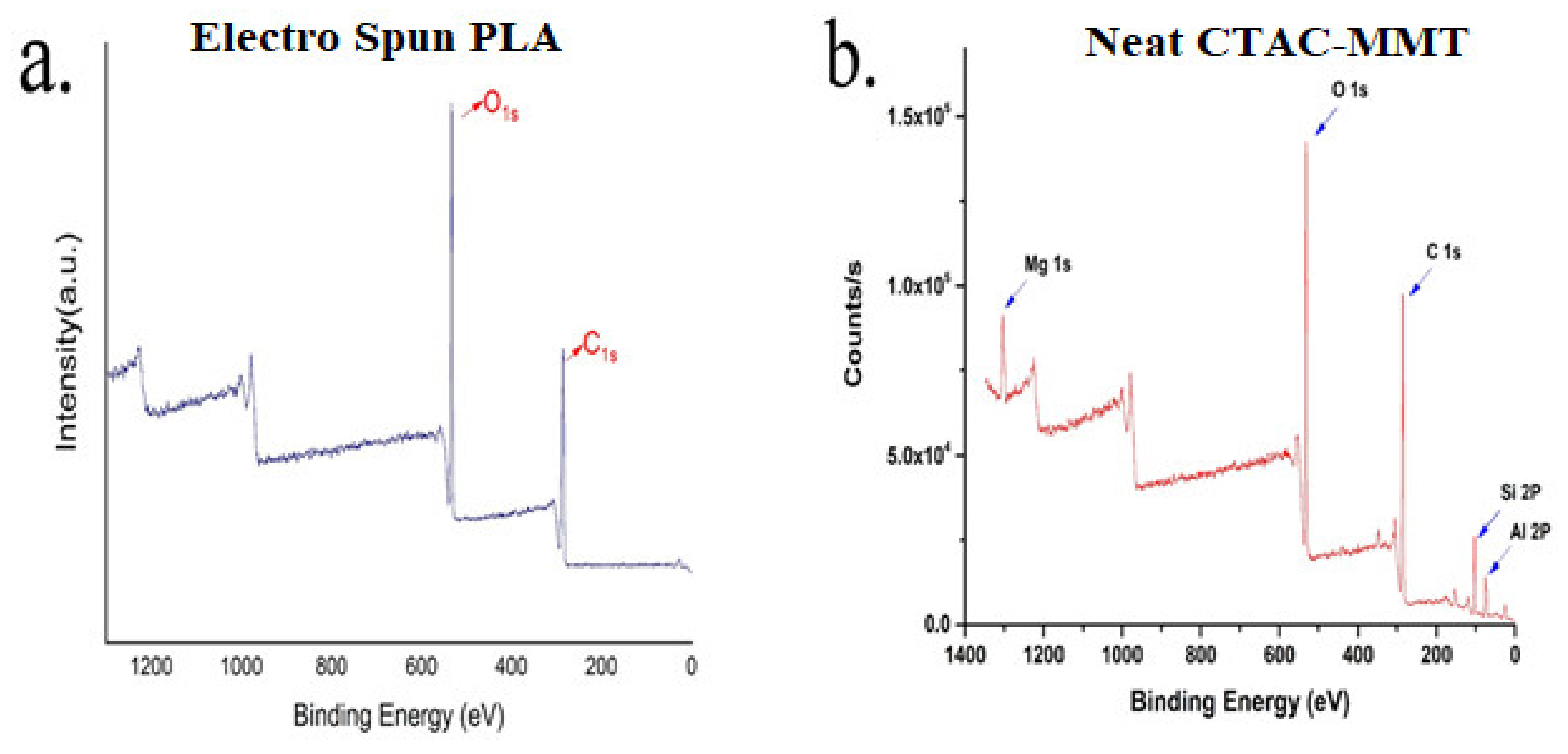
3.4. X-ray Photoelectron Spectroscopy Analysis

The XPS analysis showed the chemical status and surface elemental composition of PLA and PLA/CTAC-MMT composites. A wide survey scan of XPS spectra was taken, and the peaks corresponding to O and C of PLA were shown in (Figure 8a) and (Figure 8b) representing the presence of Mg, Al, and Si in a spectrum of CTAC-MMT. The O, C, Si, Al, and Mg elements in the PLA/CTAC-MMT nanocomposites represent the successful formation of the composite [56,57,58,59].

3.5. X-ray Diffraction (XRD) Analysis

X-ray diffraction (XRD) was applied to analyze the existence and distribution of the nano-clays in the PLA matrix. The degree of dispersion determined whether layered silicate nanofiber composites are intercalated or exfoliated. Intercalation can be defined as when the polymer chains enter into the interlayer regions of the nano-clay, while exfoliation is determined when the clay layers are removed and randomly spread in the polymer matrix [60]. X-ray diffraction patterns of the Neat PLA, Neat CTAC-MMT, and PLA/CTAC-MMT are depicted in Figure 9. The below-mentioned equation was used to measure the degree of crystallinity (Xc).
Xc = IcIc + K × Ia
where K is a correction factor for the crystalline phase disorder and Ia and Ic are the integrated intensities scattered over a suitable annular interval by the amorphous and the crystalline phases, respectively.
The organically modified montmorillonite through an exchange of cationic ions makes significant dispersion and exfoliation of the silicate layers into the PLA polymer matrix possible [60,61]. Figure 9 demonstrates that the diffraction peak (001) of sample PLA shifted to the right diffraction angle and the diffraction value of 2θ increased from 16.08 to 17.54 for Neat CTAC-MMT. Furthermore, by contrast with Neat CTAC-MMT, one can find some changes in PLA/CTAC-MMT but mostly the main diffraction peaks were maintained, indicating that the crystal structure of CTAC-MMT is significant as seen in XRD patterns and SEM images [57,62,63].

3.6. Contact Angle

Generally, the polymer lacks better mechanical and processing properties in the form of films that do not fit the desired wet behavior. To overcome this challenge, surface modification of polymer membranes is needed either. To achieve this, different techniques have been used for the preparation of membranes, for example, grafting, plasma-treatment, wet chemistry techniques, and coating methods, with the addition of one more step after the electrospun films are formed in order to attain the desired properties [1,2,3]. To determine the water behavior of electrospun nanofiber membranes and modified electrospun membranes, contact angle tests were conducted. The principal of the contact angle test is that a droplet of water is placed on nanofiber membranes where a contact angle θE is formed displaying the equilibrium of all complete interfacial energies involved and signifying the attraction of the surface with water. If θE is below 90°, the surface will be hydrophilic; if the contact angle is above 90°, then the surface of nanofiber membranes will be hydrophobic. Thus, θE is determined mainly by the chemical composition of the surface [4] and by the surface topography.
Contact angle test results determined the difference between neat electrospun PLA membranes and PLA/CTAC-MMT composites after applying the dip-coating method as shown in Figure 10. The average contact angles of neat electrospun polymer membrane are 143°, having the same range value as reported in previous reports [5]. Hydrophobic groups can get reoriented at the air/solid interface and the hydrogen bonds might form in the interior membrane structure. Furthermore, the comparatively higher crystallinity of the electrospun fibrous membrane makes the diffusion and transformation of water molecules difficult, resulting in surface hydrophobicity. In cooperation with CTAC-MMT, electrospun PLA membranes slightly transformed surface wettability as described in Table 3 below. The reduction in contact angle showed that composite nanofibers were formed and that they were connected to the side chains grafted on the CTAC-MMT structure. CTAC-MMT surface hydroxyls slightly improved the hydrophilicity of the PLA/CTAC-MMT composites via a dip-coating technique.

3.7. Mechanical Testing

Table 4 described the mechanical performance electrospun PLA with CTAC-MMT and without O-MMT. According to previous reports, PLA has a better tensile strength but low toughness. By using the dip-coating technique to add CTAC-MMT content in the PLA matrix, we obtained an improved the tensile strength of the electrospun membrane composites. PLA/CTAC-MMT composite mechanical performance was increased with the increase of CTAC-MMT content. We also observed better dispersion of CTAC-MMT nanoparticles in the PLA matrix. The tensile strength of electrospun PLA/O-MMT 0.1 wt.% composites was slightly increased by 20% when doing a comparison with neat electrospun PLA membranes. Similarly, PLA/CTAC-MMT 0.5 wt.% and PLA/O_MMT 1.0 wt.% composites showed a rise in tensile strength by 36% and 44%, correspondingly. The rise in the tensile strength of PLA can be ascribed to the interactions developed between the surface silanol groups and PLA chains [64,65].

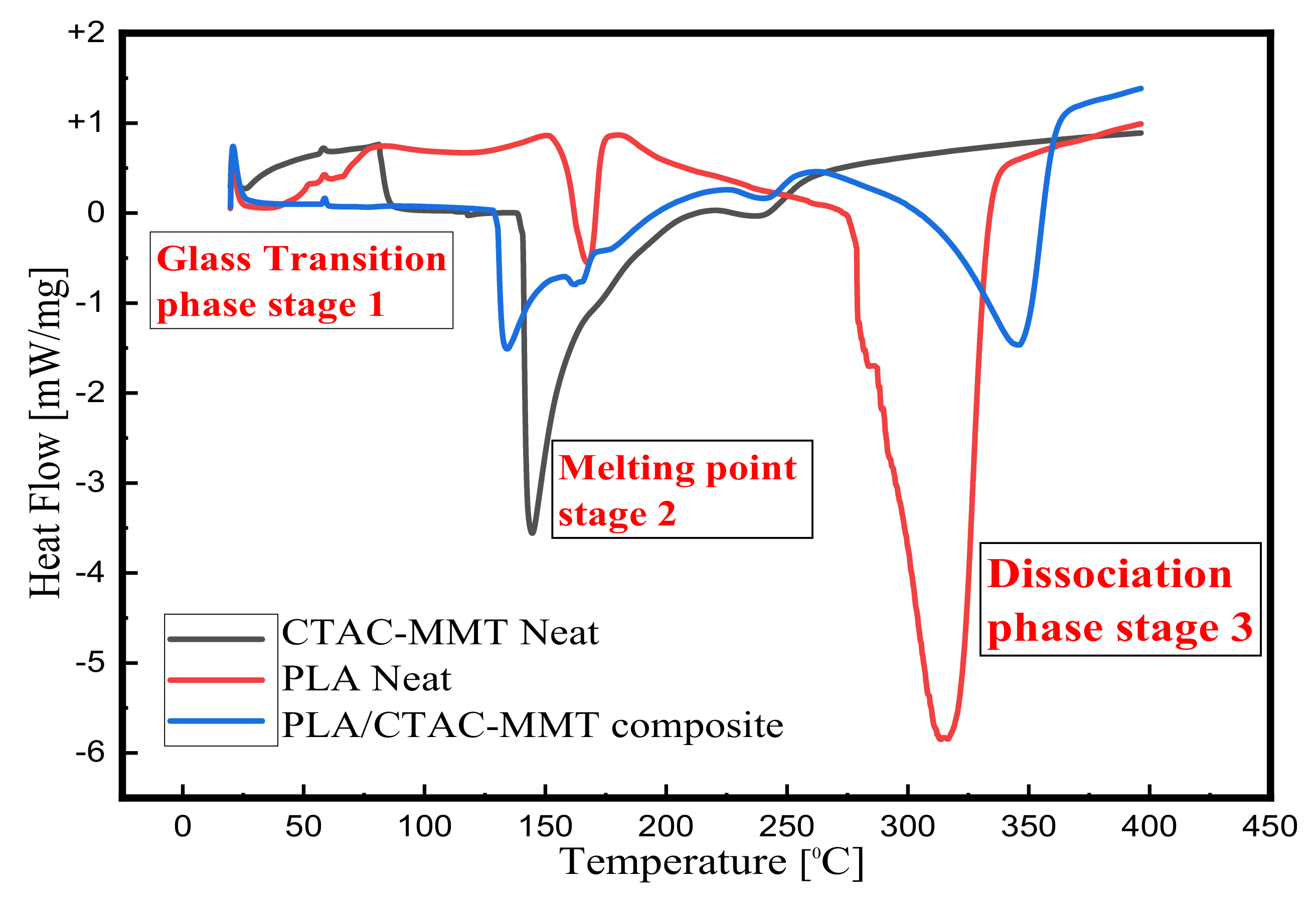
3.8. Differential Scanning Calorimeter Analysis

DSC analysis was utilized to investigate the influence of chemical composition on both the glass transition and crystallization/melting phenomena of PLA and PLA/CTAC-MMT composites. It can be seen in Figure 10 that all samples show a transition peak in the temperature range of 50–60 °C (Stage 1), which is related to the glass transition of the PLA and PLA/CTAC-MMT composites. At Stage 2, we notice that neat PLA material showed an exothermic trough at temperatures of 140–160 °C which revealed a less similar trend from works by Abdul et al. [66] and Tabi et al. [67]. Although their range showed an earlier curve at 80 °C, the difference can be attributed to the fact that the membrane used was moist and that there was possible contamination. We observed a melting point of CTAC-MMT at around 140 °C. Stage two is a very important analytical point since, after making the composite, we noticed a slight decrease in the melting point of the composite material. This is understood from the point that, with composite material, there is weaker hydrogen bonding on the surface and thus an early melting point was noticed. It is, however, very important to note that most of the melting of the composite material appeared at a lower temperature; the resistance was higher and, hence, the smaller area under the endotherm curve at stage 2 of PLA/CTAC-MMT. The next point of consideration is the degradation of the materials also known as the dissociation stage 3. PLA degradation has been reported to appear at temperatures between 350 and 400 °C (Tsutomi et al. [68]) which are slightly higher compared to our DSC results (300–350 °C). As demonstrated earlier at the melting point, there is deviation due to the pretreatment we applied (treatment in dichloromethane and tetrahydrofuran). Nevertheless, the deviation was not very significant. The most crucial impact is accounting for the increased mechanical performance of the composite on the addition of CTAC-MMT. The degradation point clearly shows that the resistance of the composite material to head degradation was immense and this is due to the compacted fiber bonding inside the composite.
Although DSC is not the appropriate method to study thermal degradation, we can observe some points that we suggest as the dissociation stage. Furthermore, as we mentioned, CTAC-MMT has attached in the interstices of the PLA nanofiber membranes structure and made weak hydrogen bonding with the PLA outer surface and fixed inside the web. Due to these new hydrogen bonds, stearic hindrances are produced and the structure intensifies to overcome its effect. This structural expansion weakens the bonds’ energy and overall affects the melting point of the resulting polymer. At stage 3, the sample was found to undergo dissociation. A comparison of the dissociation temperature of PLA with PLA/CTAC-MMT composites shows that it has significantly increased [69,70,71].

4. Conclusions

In this research work, a new composite of electrospun PLA nanofiber has been developed through the dip-coating of the CTAC-MMT solution. The newly developed composite material was characterized by morphological structure analysis. This research presents a unique structure of PLA nanofibers, which was modified by the dip-coating of the CTAC-MMT solution. We have attained a layered composite of PLA nanofibers/CTAC-MMT which was then characterized by elemental analysis. FTIR, SEM-EDS, XPS, DSC, and X-ray diffraction analytics were performed to observe the morphological structure. It was observed that, in a combination of CTAC-MMT with PLA nanofibers, the mechanical properties were slightly improved. As compared with neat PLA nanofiber, bonding between PLA nanofibers and CTAC-MMT, absorption was also increased. Results of material characterization demonstrated that CTAC-MMT can be used as a good filler for composites by the dip-coating method. Moreover, our findings reveal that PLA nanofiber diameter was affected by the concentrations of polymer solutions, as well as by varying the voltage during the electrospinning process. Furthermore, a newly prepared composite of PLA nanofibers/CTAC-MMT can be used in filtration, along with good antibacterial applications in wound dressing as well as drug delivery systems.

Author Contributions

Conceptualization, M.M. methodology, T.H.; software, M.R.K. and A.F.; Visualization, S.Y. and H.S.; formal analysis, M.W. and M.A.N.; review and editing, M.Q.S.; supervision, Q.W. All authors have read and agreed to the published version of the manuscript.

Funding

This research was funded by National first-class discipline program of Light Industry Technology and Engineering: LITE2018-21.

Acknowledgments

This research is grateful to the nanocomposite materials with training of young academic scholars, whereas instruments support of Key Laboratory of Eco Textiles, Jiangnan University, Wuxi, Jiangsu, China.

Conflicts of Interest

The authors declare no conflict of interest.

References

  1. Zhu, Y.; Liu, X.; Hu, Y.; Wang, R.; Chen, M.; Wu, J.; Wang, Y.; Kang, S.; Sun, Y.; Zhu, M. Behavior, remediation effect, and toxicity of nanomaterials in water environments. Environ. Res. 2019, 174, 54–60. [Google Scholar] [CrossRef] [PubMed]
  2. Shahrin, S.; Lau, W.J.; Goh, P.S.; Ismail, A.F.; Jaafar, J. Adsorptive mixed matrix membrane incorporating graphene oxide-manganese ferrite (GMF) hybrid nanomaterial for efficient As(V) ions removal. Compos. Part B Eng. 2019, 175, 107150. [Google Scholar] [CrossRef]
  3. Ullah, N.; Mansha, M.; Khan, I.; Qurashi, A. Nanomaterial-based optical chemical sensors for the detection of heavy metals in water: Recent advances and challenges. Trac Trends Anal. Chem. 2018, 100, 155–166. [Google Scholar] [CrossRef]
  4. Shi, J.; Zhu, Y.; Zhang, X.; Baeyens, W.R.G.; Garcia-Campaña, A.M. Recent developments in nanomaterial optical sensors. Trac Trends Anal. Chem. 2004, 23, 351–360. [Google Scholar] [CrossRef]
  5. Jia, H.-R.; Zhu, Y.-X.; Duan, Q.-Y.; Chen, Z.; Wu, F.-G. Nanomaterials meet zebrafish: Toxicity evaluation and drug delivery applications. J. Control. Release 2019, 311, 301–318. [Google Scholar] [CrossRef]
  6. Zhang, Q.; Wu, Z.; Li, N.; Pu, Y.; Wang, B.; Zhang, T.; Tao, J. Advanced review of graphene-based nanomaterials in drug delivery systems: Synthesis, modification, toxicity and application. Mater. Sci. Eng. C 2017, 77, 1363–1375. [Google Scholar] [CrossRef]
  7. Du, J.; Wong, K.K.Y. 9-Nanomaterials for Wound Healing: Scope and Advances, in Theranostic Bionanomaterials; Cui, W., Zhao, X., Eds.; Elsevier: Amsterdam, The Netherlands, 2019; pp. 211–230. [Google Scholar]
  8. Joseph, B.; Augustine, R.; Kalarikkal, N.; Thomas, S.; Seantier, B.; Grohens, Y. Recent advances in electrospun polycaprolactone based scaffolds for wound healing and skin bioengineering applications. Mater. Today Commun. 2019, 19, 319–335. [Google Scholar] [CrossRef]
  9. Papkov, D.; Beese, A.M.; Goponenko, A.; Zou, Y.; Naraghi, M.; Espinosa, H.D.; Saha, B.; Schatz, G.C.; Moravsky, A.; Loutfy, R. Extraordinary improvement of the graphitic structure of continuous carbon nanofibers templated with double wall carbon nanotubes. Acs Nano 2013, 7, 126–142. [Google Scholar] [CrossRef]
  10. Young, K.; Blighe, F.M.; Vilatela, J.J.; Windle, A.H.; Kinloch, I.A.; Deng, L.; Young, R.J.; Coleman, J.N. Strong dependence of mechanical properties on fiber diameter for polymer− nanotube composite fibers: Differentiating defect from orientation effects. Acs Nano 2010, 4, 6989–6997. [Google Scholar] [CrossRef]
  11. Rehman, A.; Ahmad, T.; Aadil, R.M.; Spotti, M.J.; Bakry, A.M.; Khan, I.M.; Zhao, L.; Riaz, T.; Tong, Q. Pectin polymers as wall materials for the nano-encapsulation of bioactive compounds. Trends Food Sci. Technol. 2019, 90, 35–46. [Google Scholar] [CrossRef]
  12. An, T.; Pant, B.; Kim, S.Y.; Park, M.; Park, S.-J.; Kim, H.-Y. Mechanical and optical properties of electrospun nylon-6, 6 nanofiber reinforced cyclic butylene terephthalate composites. J. Ind. Eng. Chem. 2017, 55, 35–39. [Google Scholar] [CrossRef]
  13. Pham, Q.P.; Sharma, U.; Mikos, A.G. Electrospinning of polymeric nanofibers for tissue engineering applications: A review. Tissue Eng. 2006, 12, 1197–1211. [Google Scholar] [CrossRef] [PubMed] [Green Version]
  14. Ghalia, M.A.; Dahman, Y. Chapter 6–Advanced nanobiomaterials in tissue engineering: Synthesis, properties, and applications. In Nanobiomaterials in Soft Tissue Engineering; Grumezescu, A.M., Ed.; William Andrew Publishing: Amsterdam, The Netherlands, 2016; pp. 141–172. [Google Scholar]
  15. Nunes, D.; Pimentel, A.; Santos, L.; Barquinha, P.; Pereira, L.; Fortunato, E.; Martins, R. 2—Synthesis, design, and morphology of metal oxide nanostructures. In Metal Oxide Nanostructures; Nunes, D., Pimentel, A., Santos, L., Barquinha, P., Pereira, L., Fortunato, E., Martins, R., Eds.; Elsevier: Amsterdam, The Netherlands, 2019; pp. 21–57. [Google Scholar]
  16. Casasola, R.; Thomas, N.L.; Trybala, A.; Georgiadou, S. Electrospun poly lactic acid (PLA) fibres: Effect of different solvent systems on fibre morphology and diameter. Polymer 2014, 55, 4728–4737. [Google Scholar] [CrossRef] [Green Version]
  17. Wen-Jie, C.; Bin-Jie, X.; Xiang-Ji, W. Fabrication and characterization of PSA nanofibers via electrospinning. J. Ind. Text. 2013, 44, 159–179. [Google Scholar] [CrossRef]
  18. Pant, B.; Park, M.; Park, S.-J. Drug delivery applications of core-sheath nanofibers prepared by coaxial electrospinning: A review. Pharmaceutics 2019, 11, 305. [Google Scholar] [CrossRef] [Green Version]
  19. Doshi, J.; Reneker, D.H. Electrospinning process and applications of electrospun fibers. J. Electrost. 1995, 35, 151–160. [Google Scholar] [CrossRef]
  20. Wang, H.; Cui, Y.; Wen, M.; E, Y.; Cheng, B. Release behavior under proteinase K and existing position of Domiphen® in its complexed poly-L-lactic acid micro-fibers electrospun from solution and W/O emulsion. J. Ind. Text. 2018, 48, 1024–1043. [Google Scholar] [CrossRef]
  21. Theron, S.A.; Zussman, E.; Yarin, A.L. Experimental investigation of the governing parameters in the electrospinning of polymer solutions. Polymer 2004, 45, 2017–2030. [Google Scholar] [CrossRef]
  22. Kim, G.-T.; Lee, J.-S.; Shin, J.-H.; Ahn, Y.-C.; Hwang, Y.-J.; Shin, H.-S.; Lee, J.-K.; Sung, C.-M. Investigation of pore formation for polystyrene electrospun fiber: Effect of relative humidity. Korean J. Chem. Eng. 2005, 22, 783–788. [Google Scholar] [CrossRef]
  23. Rehman, A.; Tong, Q.; Jafari, S.M.; Assadpour, E.; Shehzad, Q.; Aadil, R.M.; Iqbal, M.W.; Rashed, M.M.; Mushtaq, B.S.; Ashraf, W. Carotenoid-loaded nanocarriers: A comprehensive review. Adv. Colloid Interface Sci. 2020, 275, 102048. [Google Scholar] [CrossRef]
  24. Jayaramudu, J.; Reddy, G.S.M.; Varaprasad, K.; Sadiku, E.R.; Ray, S.S.; Rajulu, A.V. Structure and properties of poly (lactic acid)/Sterculia urens uniaxial fabric biocomposites. Carbohydr. Polym. 2013, 94, 822–828. [Google Scholar] [CrossRef] [PubMed]
  25. Mikes, P.; Horakova, J.; Saman, A.; Vejsadova, L.; Topham, P.; Punyodom, W.; Dumklang, M.; Jencova, V. Comparison and characterization of different polyester nano/micro fibres for use in tissue engineering applications. J. Ind. Text. 2019, 1528083719848155. [Google Scholar] [CrossRef]
  26. Ray, S.S.; Okamoto, M. Biodegradable polylactide and its nanocomposites: Opening a new dimension for plastics and composites. Macromol. Rapid Commun. 2003, 24, 815–840. [Google Scholar] [CrossRef]
  27. Yang, D.; Li, Y.; Nie, J. Preparation of gelatin/PVA nanofibers and their potential application in controlled release of drugs. Carbohydr. Polym. 2007, 69, 538–543. [Google Scholar] [CrossRef]
  28. Uddin, F. Montmorillonite: An introduction to properties and utilization. Curr. Top. Util. Clay Ind. Med. Appl. 2018, 1, 5–10. [Google Scholar]
  29. Yu, Y.-H.; Lin, C.-Y.; Yeh, J.-M.; Lin, W.-H. Preparation and properties of poly (vinyl alcohol)–clay nanocomposite materials. Polymer 2003, 44, 3553–3560. [Google Scholar] [CrossRef]
  30. Gilman, J.W.; Jackson, C.L.; Morgan, A.B.; Harris, R.; Manias, E.; Giannelis, E.P.; Wuthenow, M.; Hilton, D.; Phillips, S.H. Flammability properties of polymer− layered-silicate nanocomposites. Polypropylene and polystyrene nanocomposites. Chem. Mater. 2000, 12, 1866–1873. [Google Scholar] [CrossRef]
  31. Roy, A.; Joshi, M.; Butola, B.S.; Srivastava, A. Silver-loaded HDPE/clay nanocomposites with antibacterial property: A potential replacement for commodity polyethylene plastic. Polym. Compos. 2018, 39, E366–E377. [Google Scholar] [CrossRef]
  32. Sanchez-Valdes, S. Influence of maleated elastomer on filler dispersion, mechanical and antimicrobial properties of hybrid HDPE/clay/silver nanocomposites. J. Adhes. Sci. Technol. 2016, 30, 1006–1016. [Google Scholar] [CrossRef]
  33. Ibarra-Alonso, M.; Sánchez-Valdes, S.; Ramírez-Vargas, E.; Fernandez-Tavizón, S.; Romero-Garcia, J.; Ledezma-Perez, A.; de Valle, L.R.; Rodriguez-Fernandez, O.; Espinoza-Martinez, A.; Martinez-Colunga, J. Preparation and characterization of Polyethylene/Clay/Silver nanocomposites using functionalized polyethylenes as an adhesion promoter. J. Adhes. Sci. Technol. 2015, 29, 1911–1923. [Google Scholar] [CrossRef]
  34. Paul, D.R.; Robeson, L.M. Polymer nanotechnology: Nanocomposites. Polymer 2008, 49, 3187–3204. [Google Scholar] [CrossRef] [Green Version]
  35. Ogata, N.; Jimenez, G.; Kawai, H.; Ogihara, T. Structure and thermal/mechanical properties of poly(l-lactide)-clay blend. J. Polym. Sci. Part B: Polym. Phys. 1997, 35, 389–396. [Google Scholar] [CrossRef]
  36. Ray, S.S.; Maiti, P.; Okamoto, M.; Yamada, K.; Ueda, K. New Polylactide/Layered Silicate Nanocomposites. 1. Preparation, Characterization, and Properties. Macromolecules 2002, 35, 3104–3110. [Google Scholar]
  37. Pluta, M.; Jeszka, J.K.; Boiteux, G. Polylactide/montmorillonite nanocomposites: Structure, dielectric, viscoelastic and thermal properties. Eur. Polym. J. 2007, 43, 2819–2835. [Google Scholar] [CrossRef]
  38. Mushtaq, M.; Saba, H.; Wang, W.; Naeem, M.A.; Wei, Q. Fabrication and characterization of electrospun membranes from poly (lactic acid) and hexadecyl trimethyl ammonium chloride-modified montmorillonite clay. Journal of Industrial Textiles 2019, 2019, 1528083719831083. [Google Scholar] [CrossRef]
  39. Elshof, J.E.t. Chemical solution deposition techniques for epitaxial growth of complex oxides. In Epitaxial Growth of Complex Metal Oxides; Elsevier: Amsterdam, The Netherlands, 2015; pp. 69–93. [Google Scholar]
  40. Buapool, S.; Thavarungkul, N.; Srisukhumbowornchai, N.; Termsuksawad, P. Modeling and Analysis of the Effect of Dip-Spin Coating Process Parameters on Coating Thickness Using Factorial Design Method. Adv. Mater. Sci. Eng. 2017, 2017, 9639306. [Google Scholar]
  41. Lim, L.T.; Auras, R.; Rubino, M. Processing technologies for poly(lactic acid). Prog. Polym. Sci. 2008, 33, 820–852. [Google Scholar] [CrossRef]
  42. Garlotta, D. A literature review of poly (lactic acid). J. Polym. Environ. 2001, 9, 63–84. [Google Scholar] [CrossRef]
  43. Naeem, M.A.; Lv, P.; Zhou, H.; Naveed, T.; Wei, Q. A novel in situ self-assembling fabrication method for bacterial cellulose-electrospun nanofiber hybrid structures. Polymers 2018, 10, 712. [Google Scholar] [CrossRef] [Green Version]
  44. Jun, Z.; Hou, H.Q.; Schaper, A.; Wendorff, J.H.; Greiner, A. Poly-L-lactide nanofibers by electrospinning—Influence of solution viscosity and electrical conductivity on fiber diameter and fiber morphology. E-Polym. 2003, 3, 1618–7229. [Google Scholar] [CrossRef] [Green Version]
  45. Zong, X.H.; Kim, K.; Fang, D.F.; Ran, S.F.; Hsiao, B.S.; Chu, B. Structure and process relationship of electrospun bioabsorbable nanofiber membranes. Polymer 2002, 43, 4403–4412. [Google Scholar] [CrossRef]
  46. Arrieta, M.P.; López, J.; López, D.; Kenny, J.; Peponi, L. Development of flexible materials based on plasticized electrospun PLA–PHB blends: Structural, thermal, mechanical and disintegration properties. Eur. Polym. J. 2015, 73, 433–446. [Google Scholar] [CrossRef]
  47. Oliveira, J.E.; Mattoso, L.H.C.; Orts, W.J.; Medeiros, E.S. Structural and Morphological Characterization of Micro and Nanofibers Produced by Electrospinning and Solution Blow Spinning: A Comparative Study. Adv. Mater. Sci. Eng. 2013, 2013, 40957. [Google Scholar] [CrossRef] [Green Version]
  48. Jahangir, A.; Rumi, T.; Wahab, M.; Khan, M.; Rahman, M.; Sayed, Z. Poly Lactic Acid (PLA) Fibres: Different Solvent Systems and Their Effect on Fibre Morphology and Diameter. Am. J. Chem. 2017, 2017, 177–186. [Google Scholar]
  49. Kim, S.H.; Nam, Y.S.; Lee, T.S.; Park, W.H. Silk fibroin nanofiber. Electrospinning, properties, and structure. Polym. J. 2003, 35, 185–190. [Google Scholar] [CrossRef]
  50. Chieng, B.W.; Ibrahim, N.; Yunus, W.; Hussein, M. Effects of Graphene Nanopletelets on Poly(Lactic Acid)/Poly(Ethylene Glycol) Polymer Nanocomposites. Polymers 2013, 6, 93–104. [Google Scholar] [CrossRef] [Green Version]
  51. Kirbay, F.O.; Yalcinkaya, E.E.; Atik, G.; Evren, G.; Unal, B.; Demirkol, D.O.; Timur, S. Biofunctionalization of PAMAM-montmorillonite decorated poly (Ɛ-caprolactone)-chitosan electrospun nanofibers for cell adhesion and electrochemical cytosensing. Biosens. Bioelectron. 2018, 109, 286–294. [Google Scholar] [CrossRef]
  52. Tunc, S.; Duman, O.; Polat, T.G. Effects of montmorillonite on properties of methyl cellulose/carvacrol based active antimicrobial nanocomposites. Carbohydr. Polym. 2016, 150, 259–268. [Google Scholar] [CrossRef]
  53. Wei, Q.-B.; Fu, F.; Zhang, Y.-Q.; Tang, L. Preparation, characterization, and antibacterial properties of pH-responsive P(MMA-co-MAA)/silver nanocomposite hydrogels. J. Polym. Res. 2014, 21, 349. [Google Scholar] [CrossRef]
  54. Klika, Z.; Pustkova, P.; Praus, P.; Kovar, P.; Pospisil, M.; Maly, P.; Grygar, T.; Kulhankova, L.; Capkova, P. Fluorescence of reduced charge montmorillonite complexes with methylene blue: Experiments and molecular modeling. J. Colloid Interface Sci. 2009, 339, 416–423. [Google Scholar] [CrossRef]
  55. Huang, L. Generation of synthetic elastin-mimetic small diameter fibers and fiber networks. Macromolecules 2000, 33, 2989–2997. [Google Scholar] [CrossRef]
  56. Jamshidian, M.; Tehrany, E.A.; Imran, M.; Jacquot, M.; Desobry, S. Poly-Lactic Acid: Production, Applications, Nanocomposites, and Release Studies. Compr. Rev. Food. Sci. Food Saf. 2010, 9, 552–571. [Google Scholar] [CrossRef]
  57. Floody, M.C.; Theng, B.K.G.; Reyes, P.; Mora, M.L. Natural nanoclays: Applications and future trends—A Chilean perspective. Clay Miner. 2009, 44, 161–176. [Google Scholar] [CrossRef]
  58. Ying, Z.; Wu, D.; Wang, Z.; Xie, W.; Qiu, Y.; Wei, X. Rheological and mechanical properties of polylactide nanocomposites reinforced with the cellulose nanofibers with various surface treatments. Cellulose 2018, 25, 3955–3971. [Google Scholar] [CrossRef]
  59. Zhang, R.; Chen, C.; Li, J.; Wang, X. Preparation of montmorillonite@carbon composite and its application for U(VI) removal from aqueous solution. Appl. Surf. Sci. 2015, 349, 129–137. [Google Scholar] [CrossRef]
  60. Thirumalairajan, S.; Girija, K.; Mastelaro, V.R.; Ponpandian, N. Surface Morphology-Dependent Room-Temperature LaFeO3 Nanostructure Thin Films as Selective NO2 Gas Sensor Prepared by Radio Frequency Magnetron Sputtering. Acs Appl. Mater. Interfaces 2014, 6, 13917–13927. [Google Scholar] [CrossRef]
  61. De Azeredo, H.M. Nanocomposites for food packaging applications. Food Res. Int. 2009, 42, 1240–1253. [Google Scholar] [CrossRef] [Green Version]
  62. Reddy, M.M.; Vivekanandhan, S.; Misra, M.; Bhatia, S.K.; Mohanty, A.K. Biobased plastics and bionanocomposites: Current status and future opportunities. Prog. Polym. Sci. 2013, 38, 1653–1689. [Google Scholar] [CrossRef]
  63. Wang, G.; Zhang, D.; Li, B.; Wan, G.; Zhao, G.; Zhang, A. Strong and thermal-resistance glass fiber-reinforced polylactic acid (PLA) composites enabled by heat treatment. Int. J. Biol. Macromol. 2019, 129, 448–459. [Google Scholar] [CrossRef]
  64. Frone, A.N.; Panaitescu, D.M.; Chiulan, I.; Nicolae, C.A.; Vuluga, Z.; Vitelaru, C.; Damian, C.M. The effect of cellulose nanofibers on the crystallinity and nanostructure of poly(lactic acid) composites. J. Mater. Sci. 2016, 51, 9771–9791. [Google Scholar] [CrossRef]
  65. Lai, J.C.H.; Rahman, M.; Hamdan, S. Physical, mechanical, and thermal analysis of polylactic acid/fumed silica/clay (1.28 E) nanocomposites. Int. J. Polym. Sci. 2015, 2015, 698738. [Google Scholar] [CrossRef] [Green Version]
  66. Eng, C.C.; Ibrahim, N.; Zainuddin, N.; Ariffin, H.; Yunus, W.; Then, Y.Y.; Teh, C. Enhancement of Mechanical and Thermal Properties of Polylactic Acid/Polycaprolactone Blends by Hydrophilic Nanoclay. Indian J. Mater. Sci. 2013, 2013, 816503. [Google Scholar] [CrossRef] [Green Version]
  67. Mujeeb, A.; Lobo, A.G.; Antony, A.; Ramis, M. An experimental study on the thermal properties and electrical properties of polylactide doped with nano aluminium oxide and nano cupric oxide. Ina. Lett. 2017, 2, 145–151. [Google Scholar] [CrossRef]
  68. Tábi, T.; Suplicz, A.; Czigány, T.; Kovács, J.G. Thermal and mechanical analysis of injection moulded poly (lactic acid) filled with poly (ethylene glycol) and talc. J. Anal. Calorim. 2014, 118, 1419–1430. [Google Scholar] [CrossRef] [Green Version]
  69. Ohkita, T.; Lee, S.H. Thermal degradation and biodegradability of poly (lactic acid)/corn starch biocomposites. J. Appl. Polym. Sci. 2006, 100, 3009–3017. [Google Scholar] [CrossRef]
  70. Pyda, M.; Bopp, R.C.; Wunderlich, B. Heat capacity of poly(lactic acid). J. Chem. 2004, 36, 731–742. [Google Scholar] [CrossRef]
  71. Wang, G.; Li, A. Thermal Decomposition and Kinetics of Mixtures of Polylactic Acid and Biomass during Copyrolysis. Chin. J. Chem. Eng. 2008, 16, 929–933. [Google Scholar] [CrossRef]
Figure 1. Schematic instrumentation of the electrospinning process for the preparation of PLA nanofibers.
Coatings 10 00484 g001
Figure 2. Preparation process flow of PLA/CTAC-MMT composites to follow of electrospinning and dip-coating technique.
Coatings 10 00484 g002
Figure 3. Concentration effect on nanofiber morphology; SEM of PLA nanofibers at concentrations, 8% w/v (a), 10% w/v (b), 12.5% w/v (c), 15% w/v (d), 15% w/v (e) with CTAC-MMT.
Coatings 10 00484 g003
Figure 4. PLA fiber-diameter distribution with different solution concentrations; (a) 8%; average diameter 0.7 μm, (b) 10%; average diameter 0.9 μm, (c) 12.5%; average diameter 1.1 um, (d) 15%; average diameter 1.5 μm with CTAC-MMT.
Coatings 10 00484 g004
Figure 5. FT-IR spectra of the methanol treated PLA nanofiber (solid line) as-spun PLA nanofiber (a); (b) Neat electrospun PLA nanofiber (Black), Neat CTAC-MMT (Red) and PLA/CTAC-MMT nanocomposite (Blue), (c) PLA/CTAC-MMT fibers (b); (CTAC-MMT 1%/PLA 10% (blue), CTAC-MMT 0.5%/PLA (red), 10% CTAC-MMT 1%/PLA 10% (black)) (c).
Coatings 10 00484 g005
Figure 6. SEM-EDS elemental mapping images of PLA; (a) C & O mapping, (b) C mapping, and (c) O mapping.
Coatings 10 00484 g006
Figure 7. SEM-EDS elemental mapping images of PLA/CTAC-MMT nanocomposites; (a) O, Mg, Al, and Si mapping, (b) Mg mapping, (c) Al mapping (d) Si mapping.
Coatings 10 00484 g007
Figure 8. The graphic representation of XPS; (a) XPS spectrum of high-resolution C/O on PLA and, (b) PLA/CTAC-MMT.
Coatings 10 00484 g008
Figure 9. XRD patterns of Neat PLA (Black), Neat CTAC-MMT and PLA/CTAC-MMT nanocomposites.
Coatings 10 00484 g009
Figure 10. DSC of PLA, Neat CTAC-MMT, and PLA/CTAC-MMT nanocomposites.
Coatings 10 00484 g010
Table 1. Solvent properties used to dissolve the Polylactic acid. Viscosity is represented by η, ε is the dielectric constant, surface tension is σ, and δ is the solubility factor.
SolventBoiling Point (°C)H (mPa·s)Electrical Conductivity (μS·cm−1)εσ (mN/m)δ (cal1/2 cm−3/2)
DCM400.4494.3 × 10−59.1289.7
DMF1530.9206.0 × 10−236.73512.1
THF660.4804.5 × 1017.6289.1
Table 2. Effect of polymer concentration on solution viscosity, surface tension, conductivity, and fiber diameter [45].
PLA Concentration
% w/v
Solution Viscosity
mPa·s
Surface Tension
mN·m−1
Conductivity
μS·cm−1
Mean Nanofiber
Diameter
522 ± 929 ± 0.31.98Few nanofibers,
mainly beads
7.572 ± 729 ± 0.22.93223 ± 57
10213 ± 729 ± 0.63.40303 ± 88
12.5667 ± 6229.6 ± 0.93.87462 ± 125
151457 ± 14729.9 ± 0.93.60685 ± 206
Table 3. Contact angle and water absorption data for electrospun PLA nanofibers membrane and PLA/CTAC-MMT composite.
SamplesWater Absorption
%
CV wa
%
Contact AngleCV.cv
%
PLA0.450.040141 ± 2.82.8
PLA/O-MMT 0.1%0.550.062139 ± 1.71.7
PLA/O-MMT 0.5%0.600.076135 ± 1.71.7
PLA/O-MMT 1.0%0.700.05131 ± 1.91.9
Table 4. Tensile strength and elongation at break data for PLA and PLA/CTAC-MMT composites.
SamplesTensile Strength (MPA)Standard
(σ)
Tensile ModulusStandard
(σ)
Elongation at Break, %Standard
(σ)
PLA-02.50.114.501.2580.201.00
PLA/CTAC-MMT 0.1%3.00.9815.01.3278.00.80
PLA/CTAC-MMT 0.5%3.40.1515.61.1579.21.05
PLA/CTAC-MMT 1.0%3.60.216.01.5278.51.15

