Abstract
The active controlled hydrostatic bearing is becoming more and more popular because of its accuracy, safety, as well as low vibration and noise. In this paper, we present a design approach for a hydrostatic thrust bearing system, where the analytical nonlinear state space equation of the system is established first, and then three kinds of control inputs are investigated and compared to each other. It is found that, by selecting the supply pressure as the control input, we could obtain an affine nonlinear system, which could be linearized by the feedback linearization method, and its robustness could be enhanced by the sliding mode control method. The tracking control law could be easily obtained with the linearized system. The simulation verifies the effectiveness of the nonlinear control law. The proposed nonlinear control model might have a positive effect on the improvement of the machining accuracy, safety, and vibration absorption.
1. Introduction
The requirements of high accuracy and reliability demand the high lubrication performance of bearing. Many researchers [1,2,3] have focused on the effect of surface texture on the bearing performance. It was found that the lubrication performance of the textured bearing could be improved with appropriate surface texture geometry and texture distribution [3]. Another way for improving the performance of the bearing is to control the bearing. The design of a nonlinear control system for hydrostatic bearings is related to the fields of tribology, dynamics, and control [4]. The pressure distribution and dynamic response of a hydrostatic bearing are essential for achieving trajectory tracking.
Many scholars have studied the dynamic response of hydrostatic bearings. For example, Pang [5] studied the transient characteristics of a hydrostatic bearing under a step load, where the dynamic response of the system was obtained through a linearized transfer function. Tully [6] studied the static and dynamic performances of a hydrostatic thrust bearing compensated with a variable-flow restrictor. Yoshimoto [7] studied the step response of hydrostatic journal bearings with self-controlled restrictors by employing a floating disk. Wang [8] studied the dynamic characteristics of hydrostatic thrust bearings with a membrane restrictor, where the dynamic model of a bearing is established and solved numerically to obtain its transient response. All those works mainly analyzed the effects of the main parameters of a bearing system on its transient characteristics without mentioning their active control.
With the development of control technology, active hydrostatic bearings are becoming popular in industrial fields. To our best knowledge, active hydrostatic systems can be divided into three classes according to the control inputs:
- (1)
- Control the viscosity by using magnetorheological fluids.
For example, Hesselbach and Abel-Keilhack [9] proposed an active hydrostatic bearing which uses magnetorheological fluids. Using a variable external magnetic field, the viscosity of a magnetorheological fluid can be changed to maintain constant bearing gap with changing loads.
- (2)
- Control the recess pressure by using an active controlled restrictor.
For example, Morosi [4] and Fabian [10] proposed an actively-controlled gas bearing, where a piezoelectrically controlled jet is used to control the fluid pressure between the bearing surface and the rotating shaft. Mizumoto [11] proposed an active aerostatic bearing by incorporating an active orifice restrictor, where the stiffness and rotational accuracy of the system could be improved.
- (3)
- Control the supply pressure by using an active controlled pump.
For example, using hydraulic servo systems, Santos [12] proposed two kinds of active hydrostatic bearings, where the results showed an increase in damping and stabilization. Ryu [13] proposed, by controlling the feed pressure, the hybrid gas bearing could eliminate the vibration of the rotor when the critical speed of the system is crossed.
In a previous work, Santos [12] used a linearized model around the equilibrium position. However, a hydrostatic bearing is a highly nonlinear system as it contains a nonlinear component (oil film). A linearized model can only guarantee the performance of a system in a small region around the equilibrium position. To obtain a desirable global system performance, the nonlinear control is essential. Literature [4,10,11] used a combination of bearing displacements and velocities as control inputs to increase the stiffness and damping coefficients of a system, while the trajectory tracking was ignored.
In this paper, the pressure distribution in a hydrostatic thrust bearing is described analytically, and the nonlinear state space equation of the hydrostatic bearing is established. The analytical state space equation is then used to develop the tracking control law based on the feedback linearization method [14]. All three kinds of active bearing systems are explored using a model-based approach. The mathematical formulations of the three active bearing models are presented in Section 2 and their simulations are presented in Section 3. The goal of this paper is to design a nonlinear control system for hydrostatic thrust bearings, so as to improve the accuracy and safety of the system.
2. Mathematical Model
2.1. Model 1: Controlling the Fluid Viscosity
Consider an externally pressurized circular thrust bearing connected to a constant pressure pump. The schematic of the system is shown in Figure 1. The dynamic model of the bearing is given by:
where f is the fluid force of the oil film acting on the bearing, w is the external load, M is the mass of the bearing, and h is the displacement.
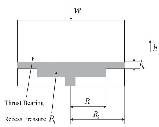
Figure 1.
Schematic of hydrostatic thrust bearing.
The fluid force in Equation (1) depends on the pressure distribution of the oil film. The pressure in the recess region is assumed to be constant, while the pressure in the restricted region of the hydrostatic thrust bearing is governed by the Reynolds equation [8]:
where is the oil viscosity. The solution of the Reynolds equation is obtained as:
Substituting the boundary condition , , the arbitrary constants and could be obtained by solving the following equation:
The pressure distribution in the restricted region is given by:
The fluid force in the restricted annular region is given by [8]:
The total fluid force of the oil film could be obtained as:
The state space equation of the system and the design of the controller will depend upon the selection of control inputs. For the first class of the active hydrostatic bearing system, we choose to control the fluid viscosity, i.e., the oil viscosity is treated as the control input . We rewrite the constant terms in Equation (7) as:
The fluid force f turns into:
The state space variable is . The state space equation can be obtained as:
where , , and . It is an affine nonlinear system. The relative degree and order of the system are the same. Hence, the nonlinear system can be fully linearized [14]. The control input could be chosen as follows:
where is the desired output and is the tracking error. We can select and to achieve exponentially convergent tracking.
2.2. Model 2: Active Membrane Restrictor
For the second class of the system, a subsystem needs to be introduced for controlling the bearing recess pressure. For example, consider the hydrostatic bearing compensated with a membrane restrictor, the schematic of which is shown in Figure 2. The dynamic behavior of the membrane is described as follows:
where m is the mass of membrane, k is the stiffness of the membrane, is the supply pressure, is external force acted on the top of membrane which is considered as the control input, and is the total fluid force acted on the bottom of membrane and can be expressed as:
where is the fluid force of the restricted annular region, and the pressure distribution in the restricted region is expressed by Equation (3), for which the arbitrary constants and could be obtained by substituting the boundary condition and . is obtained as:

Figure 2.
Schematic of hydrostatic thrust bearing compensated with a membrane restrictor.
The rate of flow into the bearing is expressed as [8];
The rate of flow out of the bearing is given by:
The continuity equation of the bearing is given by:
Substituting pressure distributions of bearing and restrictor into Equations (16), (17), and (18), could be obtained by:
The total force applied on the bearing could be obtained by substituting Equation (19) into Equation (10) and Equation (1), while the total force applied on the membrane could be obtained by substituting Equation (19) into Equations (5) and (13)–(15). The state space vector of the system is , and the state space equation of the system could be obtained as:
This system could not be linearized by the feedback linearization method, and the nonlinear control of the second class of system is still an open challenge.
2.3. Model 3: Active Pressure Supply System
The third kind of the system takes the supply pressure as the control input. For example, the hydrostatic thrust bearing compensated with a capillary restrictor, which is externally pressurized by an active pressure supply system, is shown in Figure 3:
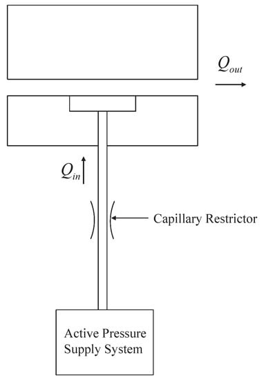
Figure 3.
Externally pressured hydrostatic bearing compensated with a capillary restrictor.
The rate of flow into the bearing is given by:
where d is the diameter of capillary restrictor, L is the length of capillary restrictor, and is the supply pressure.
The rate of flow out of the bearing is given by:
The continuity equation of the bearing is given by:
Substituting pressure distribution of bearing into Equation (23), the relationship between and is given by:
Substitute Equation (24) into Equations (1) and (10), the state space model of the hydrostatic thrust bearing is given by:
where , , , where w is the external load. is the supply pressure that is considered as a control input.
When we differentiate the output h twice, the input u appears. The relative degree and order of the system are the same. Hence, the nonlinear system can be fully linearized [14]. However, the disturbance force during the operation, and also modeling inaccuracies, will have strong adverse effects on the system. Hence, the robust control should be taken into consideration. The sliding mode control is an effective robust control method, the main idea of which is to design a sliding surface to which the desired system trajectory must belong. The advantage of this method is that the system behavior is insensitive to modeling inaccuracies and operational disturbances. However, it may suffer from the chattering problem caused by the switching frequency of the control devices. A straightforward approach to avoid chattering is to smoothen the discontinuity in the sign function by using the saturation function. The sliding mode surface is defined as [14]:
where is tracking error, is the desired trajectory, is a positive constant. The dynamics while in sliding mode can be written as:
The continuous control law that would achieve is:
In order to achieve robust performance despite disturbance on the system, we add to a saturation function across the sliding mode surface:
where k is a large enough constant to guarantee the robustness of the system, and is the thickness of the boundary layer neighboring the sliding mode surface.
3. Results
In order to verify the effectiveness of the proposed models, computer simulations were performed for the hydrostatic thrust bearing system, and the following calculation procedure was carried out:
- (1)
- Assume the value of the static external load, w.
- (2)
- Obtain the initial positions of the bearing , and the membrane , the initial velocities of the bearing , and the membrane , the initial accelerations of the bearing , and the membrane and the supply pressure .
- (3)
- By solving the continuity equation of the bearing, we can obtain the recess pressure using Equations (19) and (24).
- (4)
- Using Equations (1), (12), (13), and (29), the bearing displacements h, and the membrane displacements x at the next time step are obtained using the Euler method. Time increment of s is used in calculation.
- (5)
- Repeat the calculation steps (3) and (4) until a given time length is completed.
The values of the system related various parameters are given in Table 1.

Table 1.
Simulation parameters.
In model 1, fluid viscosity is taken as the control, and the control law is valid when the velocity of the thrust bearing is not zero. From Equation (12), one can see that, when the velocity of the bearing is zero, the control input would achieve infinity. As shown in Figure 4, under constant supply pressure Mpa, the initial bearing acceleration is and external load 1500 N, the hydrostatic bearing system is stable and the output converges to with the controller in Equation (12).
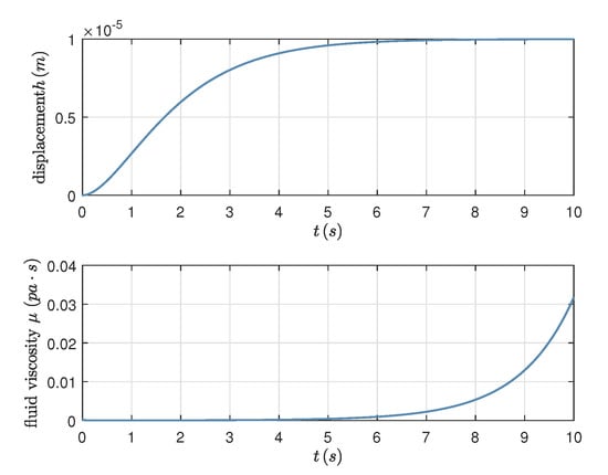
Figure 4.
Feedback linearization control input and resulting tracking performance.
In model 2, the second order subsystems of the hydrostatic bearing and the membrane restrictor are coupled through the continuity equation. The external force acting on the top of the membrane is taken as the control input. The dynamic responses of the hydrostatic thrust bearing can be seen in Figure 5. Without the control input, the bearing displacement converges to a constant with supply pressure Mpa and external load N. Under the control input , the steady-state bearing displacement become a sinusoidal wave with amplitude of 2.0539 m, when control input , the steady-state bearing displacement is no more a simple frequency sinusoidal wave, which is clear in the power spectrum of the system outputs as shown in Figure 6. Under control input , the power spectrum contains a higher frequency component.
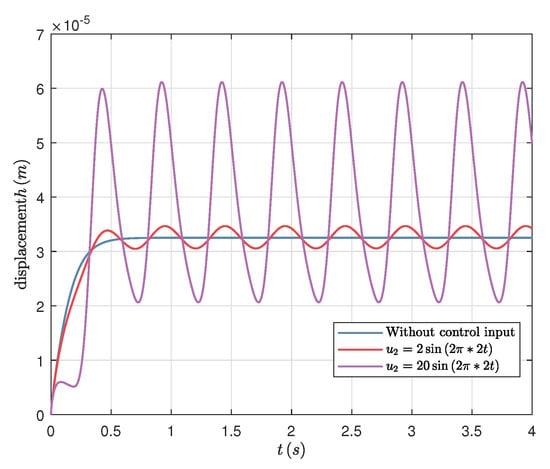
Figure 5.
Dynamic responses of hydrostatic bearing compensated with an active membrane restrictor.
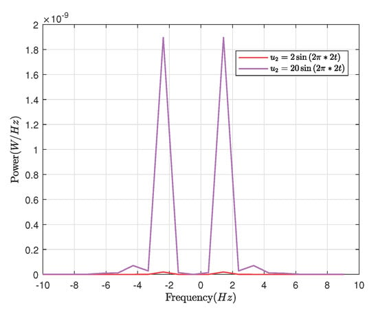
Figure 6.
Power spectrum of the steady-state response.
In model 3, a disturbance force exists. , , 1000 N. With the sliding mode controller in Equation (29), the system steady-state output converges to the desired as shown in Figure 7. determines the convergence rate of the system output, and the system output converges faster with increasing . The higher convergence rate will lead to a larger control input.
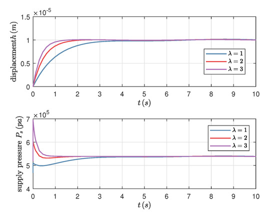
Figure 7.
Control input and tracking performance under .
4. Conclusions
In this paper, the design of a nonlinear control system for active lubrication of hydrostatic thrust bearing is investigated. From the study, we draw the following conclusions:
- (1)
- The analytical state space equation is required to design the nonlinear control law. For a circular thrust bearing, the one-dimensional Reynolds equation has analytical solutions. For other types of hydrostatic bearings, such as journal bearing, close form analytical solutions can be obtained, and the modeling error can also be handled through robust control.
- (2)
- Controlling of the trajectory tracking is not easy. The control input has a strong influence on the controlling effect: (a) If fluid viscosity is taken as the control input, the system can be controlled at the transient response stage only. Since the viscosity of a magnetic fluid can be changed in a limited range only, the desired trajectory will also be limited. (b) Addition of an active restrictor to the system is the cheapest and most convenient way to control the bearing trajectory. However, the system becomes very complicated, and hence also the tracking of the trajectory. (c) Taking the supply pressure as the control input, the system can be linearized and the sliding mode control can also be applied to ensure the robustness, but the drawback is that a complicated active pressure supply system is needed.
Author Contributions
Writing—original draft preparation, Y.S.; writing—review and editing, W.P., S.C., and P.G.; project administration, C.L. All authors have read and agreed to the published version of the manuscript.
Funding
This work is supported by the Shandong Provincial Natural Science Foundation (No. ZR2019MEE034), the National Natural Science Foundation of China (Grant No. 51975337), and the Focus on Research and Development Plan in Shandong Province (No. 2017CXGC0803).
Acknowledgments
The authors would like to thank all the people who helped to produce this article.
Conflicts of Interest
The authors declare no conflict of interest.
References
- Dadouche, A.; Conlon, M.J. Operational performance of textured journal bearings lubricated with a contaminated fluid. Tribol. Int. 2016, 93, 377–389. [Google Scholar] [CrossRef]
- Vlădescu, S.C.; Medina, S.; Olver, A.V.; Pegg, I.G.; Reddyhoff, T. Lubricant film thickness and friction force measurements in a laser surface textured reciprocating line contact simulating the piston ring–liner pairing. Tribol. Int. 2016, 98, 317–329. [Google Scholar] [CrossRef]
- Tala-Ighil, N.; Fillon, M. A numerical investigation of both thermal and texturing surface effects on the journal bearings static characteristics. Tribol. Int. 2015, 90, 228–239. [Google Scholar] [CrossRef]
- Morosi, S.; Santos, I.F. Active lubrication applied to radial gas journal bearings. Part 1: Modeling. Tribol. Int. 2011, 44, 1949–1958. [Google Scholar] [CrossRef]
- Pang, Z.; Wang, S.; Liu, Q.; Chi, W. Theoretical and experimental-study of the dynamic transient characteristics of a hydrostatic bearing. Wear 1993, 160, 27–31. [Google Scholar]
- Tully, N. Static and dynamic performance of an infinite stiffness hydrostatic thrust bearing. J. Tribol.-Trans. ASME 1977, 99, 106–112. [Google Scholar] [CrossRef]
- Yoshimoto, S.; Kikuchi, K. Step response characteristics of hydrostatic journal bearings with self-controlled restrictors employing a floating disk. J. Tribol.-Trans. ASME 1999, 121, 315–320. [Google Scholar] [CrossRef]
- Wang, C.; Cusano, C. Dynamic characteristics of externally pressurized, double-pad, circular thrust-bearings with membrane restrictors. J. Tribol.-Trans. ASME 1991, 113, 158–165. [Google Scholar] [CrossRef]
- Hesselbach, J.; Abel-Keilhack, C. Active hydrostatic bearing with magnetorheological fluid. J. Appl. Phys. 2003, 93, 8441–8443. [Google Scholar] [CrossRef]
- Pierart, F.G.; Santos, I.F. Active lubrication applied to radial gas journal bearings. Part 2: Modelling improvement and experimental validation. Tribol. Int. 2016, 96, 237–246. [Google Scholar] [CrossRef]
- Mizumoto, H.; Arii, S.; Kami, Y.; Goto, K.; Yamamoto, T.; Kawamoto, M. Active inherent restrictor for air-bearing spindles. Precis. Eng. 1996, 19, 141–147. [Google Scholar] [CrossRef]
- Santos, I.F.; Scalabrin, A. Control System Design for Active Lubrication With Theoretical and Experimental Examples. J. Eng. Gas Turbines Power 2002, 125, 75–80. [Google Scholar] [CrossRef]
- San Andrés, L.; Ryu, K. Hybrid Gas Bearings With Controlled Supply Pressure to Eliminate Rotor Vibrations While Crossing System Critical Speeds. J. Eng. Gas Turbines Power 2008, 130, 062505. [Google Scholar] [CrossRef]
- Slotine, J.J.E.; Li, W. Applied Nonlinear Control; Prentice Hall: Englewood Cliffs, NJ, USA, 1991; Volume 199. [Google Scholar]
© 2020 by the authors. Licensee MDPI, Basel, Switzerland. This article is an open access article distributed under the terms and conditions of the Creative Commons Attribution (CC BY) license (http://creativecommons.org/licenses/by/4.0/).