Abstract
Optical sensors fabricated in zeolite nanoparticle composite films rely on changes in their optical properties (refractive index, n, and thickness, d) to produce a measurable response in the presence of a target analyte. Here, ellipsometry is used to characterize the changes in optical properties of Linde Type L (LTL) zeolite thin films in the presence of Cu2+ ions in solution, with a view to improving the design of optical sensors that involve the change of n and/or d due to the adsorption of Cu2+ ions. The suitability of two different ellipsometry techniques (single wavelength and spectroscopic) for the evaluation of changes in n and d of both undoped and zeolite-doped films during exposure to water and Cu2+-containing solutions was investigated. The influence of pre-immersion thermal treatment conditions on sensor response was also studied. Due to the high temporal resolution, single wavelength ellipsometry facilitated the identification of a Cu2+ concentration response immediately after Cu2+ introduction, indicating that the single wavelength technique is suitable for dynamic studies of sensor–analyte interactions over short time scales. In comparison, spectroscopic ellipsometry produced a robust analysis of absolute changes in film n and d, as well as yielding insight into the net influence of competing and simultaneous changes in n and d inside the zeolite-doped films arising due to water adsorption and the ion exchange of potassium (K+) cations by copper (Cu2+).
1. Introduction
Sensors are being developed for every possible aspect of modern life, ranging from the detection of air pollutants [1] and food contaminants [2], monitoring health biomarkers [3,4], and even assisting in the detection of extra-terrestrial life [5]. There are many characteristics of an effective sensor, including high sensitivity, selectivity, high signal-to-noise ratio, fast response time, and reliability/stability. Sensors should ideally also be manufacturable at relatively low cost and have a reasonable shelf life that makes them cost-effective to use.
Optical diffraction grating-based sensors respond to an analyte or environmental stressor via a change in their optical properties, namely grating refractive index, n, refractive index modulation, Δn, and/or thickness, d. In the case of surface relief grating configuration sensors, Δn is the difference in refractive index, n, between the surface relief grating material and the surrounding medium. For volume grating configuration sensors, Δn is the difference in the refractive index, n, between illuminated and non-illuminated regions inside the grating. In the case of transmission-mode diffraction grating-based sensors illuminated with a probe beam (with incident intensity Io), any change in the value of Δn or d will vary the phase difference, φ, between the beams propagating along the zero (It) direction, and the higher orders (Id) of diffraction from the grating. For thin gratings operating in the Raman-Nath regime [6], the diffraction efficiency, η, can be related to φ via:
where Jm is the Bessel function of the order m, and φ is given by:
where λr is the wavelength of the probe beam and θB is the Bragg angle. Thus, changes in n, Δn and d due to analyte exposure can be indirectly measured via the η. Recently, Sabad-e-Gul et al. implemented this approach for the development of a surface relief diffraction grating (SRG)-based sensor for the detection of heavy metal ions in water [7]. The SRG-based sensor, fabricated via the holographic lithography of an acrylate photopolymer surface, which is subsequently functionalized with zeolite nanoparticles, successfully detected low concentrations of copper (Cu2+), Pb2+ and Ca2+ cations. It is postulated that the obtained change in η results from the adsorption of the metal ions onto the zeolite nanoparticles on the SRG surface, thereby changing the n of the functionalizing component (i.e., the zeolite nanoparticles) and consequently changing Δn.
While this indirect measurement technique is a straightforward and fast method for sensor evaluation and characterization, this approach provides limited information on the underlying sensor operation mechanism, such as the relative contribution of simultaneous and competing changes in grating n, Δn and d to the overall measured sensor response. Moreover, due to the nature of the Bessel function in Equation (1), it is not readily possible to ascertain from a change in η alone whether φ is increasing or decreasing as a result of analyte exposure. Theoretical modelling of the processes can be conducted; however, models require assumptions and a robust model has yet to be reported. It is thus preferable to directly measure the changes in grating n and d due to analyte exposure. Such measurements will facilitate the direct study of sensor–analyte interactions, which will facilitate the enhanced understanding, design and fabrication of optical sensors.
Here, the use of ellipsometry as a characterization tool to provide further insight into optical sensor operation and zeolite–analyte interactions is presented. Ellipsometry is a highly sensitive optical technique that uses polarized light to measure the dielectric properties, such as refractive index, of a thin film or layer system [8,9]. A beam of light with a known polarization state is transmitted or reflected from the surface of the thin film, causing a change in its polarization state. The modified polarization state can be decomposed into the reflection coefficients, rp and rs, as derived by Fresnel, of the parallel and normal components of the electric field with respect to the plane of incidence. Ellipsometry measures the ratio of rp and rs (known as the ellipsometric ratio, ), and uses this to calculate the ellipsometric angles, Δ and :
The angle of incidence, θ, of the light beam is selected to be near Brewster angle of the substrate in order to maximize the difference between rp and rs. Following the measurement of Δ and , a layer model is established for the thin film, which consists of any known optical constants (n, k) and thicknesses (d) of all individual sequential layers within the thin film. Using an iterative approach, the unknown optical constants and/or thicknesses are then varied until the best match for the measured values of Δ and is obtained. For increased accuracy, as much information as possible regarding the layer model should be known in advance.
The advantages of ellipsometry are obvious; it is a non-destructive, non-contact and non-invasive characterization technique that readily achieves sub-nanometer resolution in thickness. Due to this high sensitivity, its principles have even sometimes been used as a sensor transduction mechanism [10,11].
The current study aims at developing a better understanding of the changes to the nanozeolite-doped thin film that result as a consequence of its exposure to a target analyte. In addition, consideration will be given to the advantages and limitations of both the single wavelength and spectroscopic ellipsometry apparatus for this particular study.
2. Materials and Methods
2.1. Synthesis and Characterisation of LTL-Type Zeolite Nanoparticles
The Linde Type L (LTL) zeolite suspensions were prepared in the following manner. Firstly, solution A was prepared by dissolving 2.19 g of KOH (ACS reagent, ≥85%, pellets, Sigma-Aldrich, Saint-Quentin Fallavier, France) and 0.49 Al(OH)3 (reagent grade, Sigma-Aldrich) in 6.94 g of doubly distilled water at room temperature and stirred until the water was clear. Solution B was prepared by dissolving 1.09 g of KOH (ACS reagent, ≥85%, pellets, Sigma-Aldrich) and 10 g of LUDOX® SM 30 colloidal silica (30 wt.% suspension in H2O, Sigma-Aldrich) in 3.47 g of doubly distilled water at room temperature and stirred until the water was clear. Afterwards, solution A was added dropwise into solution B under vigorous stirring at room temperature to achieve a non-opaque suspension, free of organic template, with the following molar composition: 5 K2O:10 SiO2:0.5 A12O3:200 H2O [12]. The as-prepared precursor mixture was aged at room temperature for 24 h prior to hydrothermal treatment at 170 °C for 18 h. Upon completing the crystallization process, the nanosized product was washed with doubly distilled water and recovered by multistep centrifugation (20,000 rpm, 40 min) until pH = 8. The final stabilized nanocrystal suspension had a concentration of approximately 1.5 wt.%.
Dynamic light scattering and X-ray diffraction measurements were carried out to determine the size of the nanoparticles and to confirm their crystalline structure, respectively. The agglomeration and average size of particles and the aggregates in the crystalline suspensions were determined using dynamic light scattering (DLS) performed with a Malvern Zetasizer Nano instrument (Malvern, UK), scattering angle of 173°, laser wavelength of 632.8 nm and output power of 3 mW). X-ray diffraction measurements were operated on a PANalytical X’Pert Pro diffractometer (Almelo, The Netherlands) using the Cu Kα monochromatized radiation (α = 1.54059 Å). A detailed crystal morphology, particle size distribution and crystallinity of the LTL zeolite were examined by field-emission scanning electron microscope (FESEM) using a TESCAN Mira (Brno, Czech Republic) operating at an accelerating voltage 30 kV, and high-resolution transmission electron microscope (HRTEM) using a Tecnai G2 30 UT (LaB6, Hillsboro, OR, USA) operated at 300 kV with 0.17 nm point resolution equipped with an EDAX EDX detector (Mahwah, NJ, USA).
2.2. Preparation of TEOS-LTL Films
As in [7], the ellipsometry measurements necessitated prolonged exposure of the zeolite films to water. In order to facilitate increased mechanical stability of the LTL-type zeolite films in solution, the LTL-type zeolites were mixed with a pre-hydrolyzed tetraethyl orthosilicate (TEOS).
The following composition was used: 24 mL TEOS, 17.5 mL ethanol, 3 mL of 0.04 M nitric acid and 12 mL of the 1.5 wt.% LTL zeolite suspension described in Section 2.1 [13]. This solution was magnetically stirred for 24 h, filtered (0.8 μm), and then spin-coated at 5000 rpm onto a Silicon wafer substrate. This procedure produced dry films with a thickness of approximately 220 nm. Reference TEOS-only (i.e., no zeolites) samples were also fabricated in the same manner. Scanning electron microscopy studies were conducted to confirm the uniform distribution of LTL-type zeolites within the TEOS-LTL film.
All samples (both TEOS-LTL and TEOS-only) were initially annealed for 3 h to ensure that the zeolite nanoparticles contained no water prior to the ellipsometric measurements. For the single wavelength ellipsometric study, the samples were annealed at 170 °C under vacuum, whereas, for the spectroscopic ellipsometric study, the samples were annealed at 170 and 320 °C in air. The second annealing temperature, 320 °C, was added in order to compensate for the difference in the annealing conditions at 170 °C (i.e., vacuum vs. air), which arose due to the difference in available equipment across the multi-national laboratories contributing to the reported work. For the data presented for each study (single wavelength and spectroscopic) identical thermal treatment conditions were used, which facilitates meaningful analysis of the data.
2.3. Ellipsometric Characterization
2.3.1. Single Wavelength Ellipsometry Experiments
A single wavelength (632.8 nm) Multiskop (Optrel GbR, Sinzing, Germany) ellipsometer was used to study the change in the optical refractive index, n, and thickness, d, of the TEOS-LTL and TEOS-only films during exposure to Cu2+ water solutions with concentrations of 0, 2 and 4 mM. A custom-built liquid cell with quartz windows allowed for the transmission of the 632.8 nm ellipsometer probe beam with minimal losses. A similar approach was successfully used by Pristinski et al. [14] for the study of thin film swelling in liquid environments. Each test film was placed in the cell, which was then filled with 90 mL of deionized water. The measurement was commenced as soon as the probe beam was correctly aligned with both the sample and detector. A value for the Δ and parameters was captured every 10 s for 700 s. After 200 s, 10 mL of a concentrated Cu2+ solution was then added to the cell, ensuring not to disturb the test film. Due to dilution, the final overall concentrations in the cell were 0, 2 and 4 mM. The experiment was carried out in this fashion in order to determine if the change observed in the Δ and parameters of the test films is due simply to water or if the metal solution has a separate effect.
Following data collection, a four-media model within the Optrel Elli v3.2 software was used to calculate values for the d and n of the test films as function of time. These four media from top to bottom are: water (n = 1.33), the test film, SiO2 (n = 1.4585, d = 3 nm) and Si (n = 3.8858, k = 0.018 [15]). The model was additionally supplied with upper and lower limits n and d of the test film: n = 1.35–1.60 and d = 140–260 nm.
2.3.2. Spectroscopic Ellipsometry Experiments
A phase modulated spectroscopic ellipsometer (UVISEL 2, Horiba JobinYvon, Longjumeau Cedex, France) was used to characterize the change over time in the refractive index, n, the extinction coefficient, k, and the thickness, d, of the TEOS and TEOS-LTL films as a function of the incident wavelength. The phase modulated ellipsometer, which contains a Xenon light source, shows higher acquisition speed compared to, for example, null ellipsometer and rotating parts ellipsometer, because of the presence of the photoelastic modulator (PEM) with modulation frequency of 50 kHz. The modulator induces temporal change in polarization state of the light thus eliminating the need of rotating polarizer, analyser and compensator.
A specially designed cell was used in the study to enable measurements in liquid environment. In the first measurement step, the sample was placed in the cell and a measurement was taken in air. Then, without disturbing the sample, the solution of Cu2+ with particular concentration (0, 2 or 4 mM) was added and the measurements were taken after 90, 500 and 1000 s.
The temporal resolution of a specific scientific instrument is provided by the manufacturer and it is given for a single wavelength. However, the specific measurement time is determined by other parameters. For these measurements, scans were performed over the wavelength range 320–800 nm using a 5 nm increment. The increment was chosen based on the estimated thickness of the sample. The time integration interval was set to 200 ms, so that an optimum signal to noise ratio was achieved, taking into account the reflectivity of the sample. Thus, the time required for a single scan at these measurement conditions was larger than 19.2 s, since some time is required to record the data at a particular wavelength and to carry out the next measurement.
For the determination of the optical constants, a four media model was implemented: silicon substrate, the studied film, a thin (1–3 nm) surface layer that contains 50% voids and water. The top layer was used for modelling the surface roughness of the studied film and its thickness is one of the parameters that was calculated. In spectroscopic ellipsometry for the determination of optical constants (n and k), the so-called dispersion models were used. They relate n and k with wavelength through different dispersion parameters that usually have physical meaning. In our case, we used the one-oscillator Lorentz model where the complex dielectric constant, is described as:
where ε∞ is the high frequency dielectric constant, εs gives the value of the static dielectric constant at a zero frequency of light, is the frequency of light (in eV), (in eV) is the resonant frequency of the oscillator, whose energy corresponds to the absorption peak and (in eV) is the broadening of the oscillator also known as damping factor. The relation between n, k and is:
where and are the real and imaginary parts of , respectively.
3. Results and Discussion
3.1. Characterisation of the LTL Nanocrystals
The size of the LTL nanoparticles was confirmed to be 50 nm, as measured by DLS (Figure 1a). The DLS provides information on the average size of the crystals as individuals and as aggregates due to random Browning motion in the suspension during the measurements. Therefore, the particle size distribution curve covers the region 25–80 nm but centered at 50 nm. In addition, the size of individual zeolite grains according to the high-resolution transmission electron microscopy study (HRTEM) was determined to be in the range 10–20 nm (Figure 2b). It can be clearly observed that the LTL sample is fully crystalline (Figure 1b) and consists of many aggregates, which are formed from single rectangular crystalline domains with well-defined edges and crystalline fringes (Figure 2b).
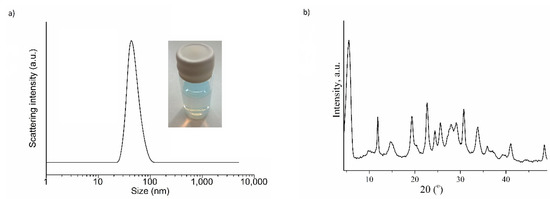
Figure 1.
Dynamic light scattering (DLS) data (a) and the X-ray diffraction (XRD) pattern (b) of the Linde Type L (LTL) zeolite nanoparticles.
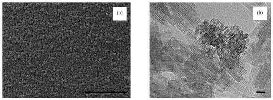
Figure 2.
SEM (Scale bar, M = 2000 nm) (a) and high-resolution transmission electron microscope (HRTEM) (Scale bar, M = 10 nm) (b) pictures of LTL nanosized zeolite.
The SEM picture in Figure 2a displays aggregates with the size of 100 to 200 nm with the particles closely connected to each other. These agglomerates are composed of crystalline single nanocrystals of rectangular shape with prominent edges with an average size of 20 nm. The aggregated crystals in the SEM pictures are due to the drying of the LTL colloidal suspension prior to the SEM study.
3.2. Single Wavelength Ellipsometric Studies
Figure 3 shows the results from the single wavelength ellipsometric measurements carried out using both undoped and doped (i.e., TEOS-only and TEOS-LTL) samples that have been exposed to water solutions of Cu2+ ions with concentrations of 0, 2 and 4 mM. All samples were thermally treated in a vacuum oven at 170 °C for 3 h in order to remove any residual water from the samples as a result of ambient humidity. A significant effort was made to minimize the period required for ellipsometer beam realignment between the addition of water and the commencement of the measurement (i.e., t = 0 s in Figure 3). This period was typically 50 ± 10 s. While some swelling of the film is expected during this period, the initial absolute values for n and d were largely consistent, implying that changes occurring during this period were minimal and consistent across all samples. Specifically, for the TEOS-LTL data shown in Figure 3, the average n at t = 0 s was 1.4412 ± 0.0029; the average d was 218.83 ± 4.00 nm. For the TEOS-only samples, the average n at t = 0 s was 1.4198 ± 0.0024; the average d was 227.63 ± 7.05 nm.
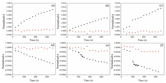
Figure 3.
(Top row) normalized thickness, d, as a function of exposure time to 0 (a), 2 (b) and 4 (c) mM Cu2+ solution; (bottom row) normalized refractive index, n, as a function of exposure time to 0 (d), 2 (e) and 4 (f) mM Cu2+ solution. Black square symbol represents tetraethyl orthosilicate (TEOS)-LTL data, and red spheroidal symbol represents TEOS-only data.
3.2.1. Dynamic Studies of Film n and d due to Exposure to Water
It can be seen (Figure 3a,d) that when exposed to water, both n and d of the reference TEOS-only films were relatively constant. This could be explained by the relatively low porosity of the undoped films, which reveals that the amount of water penetrating into the films was insignificant. The change in d (Figure 3a) was within 0.12% while the change in the films n was less than 1.3 × 10⁻⁴ (Figure 3d). It is worth noting that no significant disturbance of the samples was observed as a result of the injection of water at 200 s. This confirms that there was no mechanical instability during the injection step causing changes, thus any changes observed in presence of copper in the sample can be attributed solely to the presence of the copper analyte.
The introduction of LTL zeolite nanoparticles in the film increased swelling significantly (up to 1.2% in a 220-nm thick film) and the observed change in n is 1.1 × 10⁻³, revealing that the structure is more flexible (i.e., able to swell) as well as more porous and hydrophilic, which allows for the water molecules to penetrate the film.
3.2.2. Dynamics Studies of Film n and d due to Exposure to Copper Ions in Water
As seen from Figure 3b,c, the introduction of copper in the solution did not lead to a significant dimensional change in the TEOS-only films (within 0.13% for both 2 and 4 mM), while, in the TEOS-LTL zeolite-doped films, the swelling was similar to water solutions and within 1.2%. Nevertheless, a close examination revealed that the dynamics of the swelling is different, with a small jump at 200 s for the 4 mM concentration. One can conclude from these results that the swelling of the zeolite doped films is mainly due to the film being immersed in water and it is within 1.2% of the original thickness of the film for the first 700 s.
The examination of the dynamics of the refractive index of TEOS-LTL films under exposure to copper ions in water revealed that the rate of initial change of the refractive index after introduction of the copper ions strongly depends on their concentration (Figure 3d–f). The absolute refractive index change measured 500 s after the injection of copper ions was 7 × 10⁻⁴, 7 × 10⁻⁴ and 11 × 10−4 for samples with a concentration of 0, 2 and 4 mM correspondingly. This can be explained by the high ion exchange capacity of the LTL zeolite nanocrystals. The higher amount of Cu cations replacing the original K cations in the LTL zeolite nanocrystals leads to a higher decrease in the absolute refractive index (Figure 3).
As d increases due to swelling, the average n of the film will decrease as the TEOS-LTL matrix molecules become more separated in space. While one would expect that water replacing air will increase n of the film voids, the net effect of swelling of the TEOS-LTL matrix, which has an initially higher refractive index, likely overcomes this effect, causing an overall decrease in the n of the film with increasing water/Cu2+ exposure. This effect is not observed for the TEOS-only films, which are highly rigid. Understanding these effects is important for sensor design.
3.3. Spectroscopic Ellipsometric Studies
The spectroscopic measurements were carried out with two sets of samples: the first set was thermally treated at 170 °C for 3 h i.e., identical treatment to the samples studied by single wavelength ellipsometry except that the treatment was performed in air; the second set of samples was exposed to 320 °C degrees for 1 h in air in order to suppress any dimensional changes under exposure to water and to remove water and organic residues from the pores.
The calculated extinction coefficients, k, for the films in air, water and 4 mM Cu2+ solution are presented in Table S1. These k values are averaged over three different samples and the deviations from the average value are in the range (0.6–1) × 10−3 with the exception of 3 × 10⁻³ for the TEOS-only (170 °C) samples. Immersion does not lead to any substantial change in k, nor is some trend observed. This demonstrates that the absorption of the films at the wavelengths used in this study is negligible.
3.3.1. Studies of Film n and d due to Exposure to Water
Initially, we studied the optical behaviour of samples in pure water. Figure 4 presents the dispersion curves of the calculated refractive index, n, of both sets of samples measured prior to and after the immersion in water, while the calculated thickness values are displayed in Table 1. It is seen from Figure 4 that the refractive index of the TEOS-LTL composites annealed at both temperatures was substantially lower compared to the TEOS-only layers. The reason is that the refractive index of the LTL zeolites (~1.37) [16] is less than the refractive index of the TEOS matrix, and thus LTL addition reduces the effective refractive index of the composite. Furthermore, the annealing at higher temperature also led to a reduction in the refractive index; this effect was most pronounced for doped samples. The most probable reason is that after 170 °C annealing in air, water was still present in the pores of zeolite particles and the TEOS matrix but was then removed after the higher temperature treatment at 320 °C.
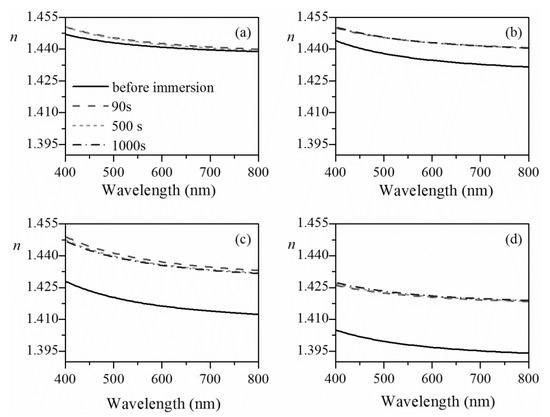
Figure 4.
Dispersion curves of refractive index of TEOS-only films annealed at 170 °C (a) and 320 °C (b) and TEOS-LTL films annealed at 170 °C (c) and 320 °C (d) immersed in water for the denoted duration. The reference curve of refractive index of the layers prior to immersion is also plotted (solid black line).

Table 1.
Calculated thickness values (in nm) and thickness change Δd = (d1000s − d90s)/d90s of undoped (TEOS-only) and doped (TEOS-LTL) films annealed at 170 and 320 °C after immersion in water for 90, 500 and 1000 s.
For all samples, the immersion in water led to an increase in the refractive index; this is expected considering the presence of porosity in the layers. Water, with a higher refractive index (n ~ 1.33) than air (n = 1), penetrates the pores, thus increasing the effective refractive index. It may be expected that with increasing the immersion time this trend will continue. However, it is interesting to note that for all samples except TEOS-LTL annealed at 320 °C, n was observed to decrease with increasing time of immersion (Figure 5). The most pronounced decrease was for samples annealed at 170 °C: decrease in n from 7 × 10⁻⁴ at 500 s to 11 × 10−4 at 1000 s was observed. The reason is the swelling of the TEOS matrix with the time of immersion led to a decrease in the overall film density, thus decreasing the refractive index. From Table 1, it can be seen that the thickness of samples annealed at 170 °C increased by 0.57% and 0.33% for the undoped (TEOS-only) and doped (TEOS-LTL) films, respectively. These results suggest that the addition of LTL zeolite particles in the TEOS matrix positively influences its mechanical stability, and dimensional changes due to immersion in water are less pronounced. Additionally, the calculated thickness changes (Table 1) show that the TEOS matrix annealed at 320 °C is more rigid compared to that annealed at 170 °C; the increase in d was only 0.19% and this explains the weaker decrease in n in this case: 1 × 10⁻⁴ at 500 s to 1.4 × 10⁻⁴ at 1000 s. Furthermore, the addition of zeolites in the TEOS matrix and annealing at higher temperature contribute to an increase in the mechanical strength of TEOS-LTL samples, thus minimizing its swelling when immersed in water (thickness change is 0.15% only). In this case, an expected increase of n was observed with the time of immersion due to the constant penetration of water in the pores: 1.8 × 10⁻⁴ at 500 s to 3.6 × 10⁻⁴ at 1000 s.
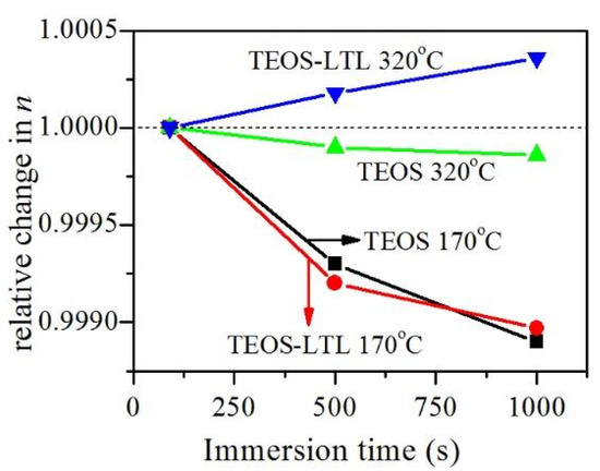
Figure 5.
Relative change of refractive index (at wavelength of 800 nm) as a function of immersion time in water.
We should note that for samples annealed at 170 °C, especially these of TEOS-only, the spectroscopic ellipsometry yielded higher changes in their d and n compared to the results obtained from single-wavelength ellipsometry. The reason is that the samples are not fully identical; the first set is annealed in air, while the second set is in vacuum. The conclusion is that annealing at a low temperature (170 °C in this case) in air is not effective enough for the TEOS matrix to become sufficiently rigid, and changes related to removing organic residues and water still take place. Considering all of the above, we decided to use only samples annealed at 320 °C for further experiments.
3.3.2. Studies of Film n and d due to Exposure to Copper Ions in Water
The relative changes of n (at wavelength of 800 nm) as a function of immersion time in pure water and Cu2+-containing water solution with a concentration of 4 mM for films annealed at 320 °C are presented in Figure 6. It was seen that, in both cases (water and Cu2+ ions), the influence of immersion was more pronounced for the TEOS-LTL samples. From the results presented above for water immersion, it has already been determined that the thickness changes in samples annealed at 320 °C are negligible and the refractive index changes are mainly due to the penetration of water inside the pores. As noted above, this is the reason for the continuous change of TEOS-LTL refractive index with immersion time, as seen in the earlier studies (Figure 5). It is also seen from Figure 6 that the changes in sample n when immersed in the copper ion solution are weaker compared to the case of water immersion. Considering that the calculated thickness changes in this case are less than 0.1%, we may conclude that the immersion of samples in Cu2+-containing solution leads to a decrease in the films’ refractive index for two reasons. The first reason is that the refractive index of copper solution is smaller than water [17], which leads to decrease of the effective refractive index of the films when the Cu2+ water solution penetrates the pores. The second reason is the decrease in the hydrophilicity of the zeolites by introducing copper; more Cu in the zeolites decreases the water content, leading to a decrease in the effective refractive index of the film. This was verified by contact angle measurement using a First Ten Angstroms (FTA200, USA) surface energy analyser (details of the measurement technique can be found in the Supplementary Material). The contact angles of the TEOS-only films and TEOS-LTL films were measured to be 62.55° and 70.50°, respectively. The increase in the contact angle value verifies the decrease in the hydrophilicity of the TEOS matrix due to the incorporation of LTL zeolites. The further increase in the contact angle of the TEOS-LTL films to 106.56° after exposure to Cu2+ ions in solution supports the claim that the hydrophilicity of the zeolite-doped film decreases due to the adsorption of copper (see Figure S1). Because for the TEOS-only films there is no change of hydrophilicity (no LTL zeolites), the decrease in n is smaller compared to the case of the TEOS-LTL films where both factors contribute to the decrease in n. The further increase in refractive index with time is due to the penetration of Cu2+ water solution inside the pores. For the TEOS-LTL samples, the difference in n of films in water and copper solution is almost the same at 500 and 1000 s—2.8 × 10⁻⁴ and 3.1 × 10⁻⁴, respectively. The same trend is observed for the TEOS-only samples, but the changes are weaker (0.9 × 10⁻⁴ and 1 × 10⁻⁴, respectively).
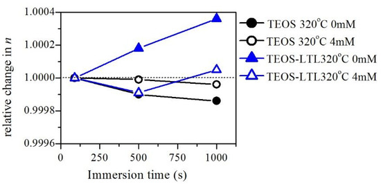
Figure 6.
Relative change in refractive index, n, (at wavelength of 800 nm) as a function of immersion time in water (solid symbols) and the solution of Cu2+ with a concentration of 4 mM (open symbols) for films of TEOS-only (circles) and TEOS-LTL (triangles) annealed at 320 °C.
4. Conclusions
The use of ellipsometry as a characterization tool to provide further insight into optical sensor operation and zeolite–analyte interactions is presented. The suitability of both single wavelength and spectroscopic ellipsometry for the evaluation of changes in the refractive index, n, and thickness, d, of zeolite-TEOS films during exposure to copper ion solutions has been investigated. Additionally, the influence of the initial film thermal treatment conditions on the response of both doped and undoped films has been studied.
Due to the short acquisition time involved, single wavelength ellipsometry offers excellent temporal resolution and thus is suitable for the real-time study of optical changes in thin films. This approach was used to study the dynamic changes in the n and d of TEOS-only and TEOS-LTL films immersed in water and copper ion solutions. Due to the competing effects of film swelling and refractive index change due to water and copper ion adsorption, no significant difference in the absolute values of n and d were observed between the different concentrations of Cu2+ ions. However, close examination reveals that the dynamics of change in n and d are different for the different Cu2+ concentrations, as well as between the TEOS-only and TEOS-LTL films. This highly sensitive measurement technique offers a unique insight into the sensor response mechanism over short timescales.
Spectroscopic ellipsometry was used as a second method for the study of the changes in TEOS-LTL film optical properties. While the temporal resolution of the spectroscopic system in this instance was limited by the necessity to acquire data over a larger wavelength range, the dispersion model used for data analysis in spectroscopic ellipsometry facilitates a more accurate estimation of the absolute values of the optical constants. Using this approach, detailed analysis of changes in n and d for the undoped and LTL zeolite doped TEOS films as a result of water and copper ion exposure was conducted. It was observed that the amount of film swelling can be controlled by the temperature at which the samples are treated before exposure to the analyte. The higher the temperature, the smaller the swelling of the TEOS films during immersion. Additionally, it was observed that the inclusion of LTL zeolites in the TEOS increases the rigidity and mechanical stability of the film under prolonged exposure to aqueous solutions.
Both the single wavelength and spectroscopic measurements of films pre-treated at 170 °C show a decrease in n after the sample is exposed to water or Cu2+-containing water solution. Samples pre-treated at 320 °C and doped with LTL zeolites show no swelling, and n slightly increases when immersed in water and decreases after exposure to copper ions. This is explained by (i) the lower refractive index of copper water solution as compared to pure water and (ii) the decrease in the hydrophilicity of zeolites with the addition of copper.
The suitability of ellipsometry for the study of optical material and sensor–analyte interactions, including the differentiation of the influence of simultaneous and competing processes, has been demonstrated. Future work will study a wider range of zeolite–analyte combinations over a wider range of annealing temperatures and conditions.
Supplementary Materials
The following are available online at https://www.mdpi.com/2079-6412/10/4/423/s1, Figure S1: Contact angle results for uncoated and coated films: SRG-surface relief grating; SRG-TEOS-sol-gel coated surface relief grating; SRG-TEOS-LTL-zeolite-doped sol-gel coated surface relief grating; SRG-TEOS-LTL-Cu II zeolite-doped sol-gel coated surface relief grating exposed to 4 mM Cu2+ solution, Table S1: Extinction coefficients at wavelength of 633 nm.
Author Contributions
Conceptualization, D.C. and I.N.; methodology, D.C., T.B., V.M., S.M., S.-e.-G., A.K., C.J.B. and I.N.; formal analysis, D.C., T.B., V.M. and I.N.; resources, D.C., T.B., V.M., S.M., C.J.B. and I.N.; writing—original draft preparation, D.C., I.N. and T.B.; writing—review and editing, D.C., T.B., V.M., S.M., S.-e.G., A.K., C.J.B. and I.N.; visualization, D.C., T.B. and V.M.; supervision, I.N. and C.J.B.; funding acquisition, I.N. and D.C. All authors have read and agreed to the published version of the manuscript.
Funding
This research was funded by the Arnold F Graves Postdoctoral Scholarship from Technological University Dublin, and a Flaherty Research Scholarship from the Ireland Canada University Foundation.
Acknowledgments
The authors would like to thank Oleg I. Lebedev from CRISMAT, CNRS-ENSICAEN, France, for preparation of the TEM images. The authors gratefully acknowledge the financial support provided for this work by the Arnold F. Graves Postdoctoral Scholarship from Technological University Dublin, and a Flaherty Research Scholarship from the Ireland Canada University Foundation. TB and VM acknowledge the support of the European Regional Development Fund within the Operational Programme “Science and Education for Smart Growth 2014–2020” under the Project CoE “National center of mechatronics and clean technologies” BG05M2OP001-1.001-0008-С01.
Conflicts of Interest
The authors declare no conflict of interest.
References
- Castell, N.; Dauge, F.R.; Schneider, P.; Vogt, M.; Lerner, U.; Fishbain, B.; Broday, D.; Bartonova, A. Can commercial low-cost sensor platforms contribute to air quality monitoring and exposure estimates? Environ. Int. 2017, 99, 293–302. [Google Scholar] [CrossRef] [PubMed]
- Yousefi, H.; Su, H.M.; Imani, S.M.; Alkhaldi, K.; Filipe, C.D.M.; Didar, T.F. Intelligent food packaging: A review of smart sensing technologies for monitoring food quality. ACS Sens. 2019, 4, 808–821. [Google Scholar] [CrossRef] [PubMed]
- Kim, J.; Campbell, A.S.; de Ávila, B.E.; Wang, J. Wearable biosensors for healthcare monitoring. Nat. Biotechnol. 2019, 37, 389–406. [Google Scholar] [CrossRef] [PubMed]
- Afsarimanesh, N.; Mukhopadhyay, S.C.; Kruger, M. Sensing technologies for monitoring of bone-health: A review. Sens. Actuators A Phys. 2018, 274, 165–178. [Google Scholar] [CrossRef]
- Nascetti, A.; Mirasoli, M.; Marchegiani, E.; Zangheri, M.; Costantini, F.; Porchetta, A.; Iannascoli, L.; Lovecchio, N.; Caputo, D.; de Cesare, G.; et al. Integrated chemiluminescence-based lab-on-chip for detection of life markers in extraterrestrial environments. Biosens. Bioelectron. 2019, 123, 195–203. [Google Scholar] [CrossRef] [PubMed]
- Raman, C.V.; Nagendra Nath, N.S. The diffraction of light by high frequency sound waves: Part 1. Proc. Indian Acad. Sci. A 1935, 32, 406–412. [Google Scholar] [CrossRef]
- Gul, S.E.; Cody, D.; Kharchenko, A.; Martin, S.; Mintova, S.; Cassidy, J.; Naydenova, I. LTL type nanozeolites utilized in surface photonics structures for environmental sensors. Microporous Mesoporous Mater. 2018, 261, 268–274. [Google Scholar] [CrossRef]
- Nestler, P.; Helm, C.A. Determination of refractive index and layer thickness of nm-thin films via ellipsometry. Opt. Express 2017, 25, 27077–27085. [Google Scholar] [CrossRef] [PubMed]
- Harke, M.; Teppner, R.; Schulz, O.; Motschmann, H.; Orendi, H. Description of a single modular optical setup for ellipsometry, surface plasmons, waveguide modes, and their corresponding imaging techniques including Brewster angle microscopy. Rev. Sci. Instrum. 1997, 68, 3130–3134. [Google Scholar] [CrossRef]
- Arwin, H. Is ellipsometry suitable for sensor applications? Sens. Actuators A Phys. 2001, 92, 43–51. [Google Scholar] [CrossRef]
- Moirangthem, R.S.; Chang, Y.C.; Hsu, S.H.; Wei, P.K. Surface plasmon resonance ellipsometry based sensor for studying biomolecular interaction. Biosens. Bioelectron. 2010, 25, 2633–2638. [Google Scholar] [CrossRef] [PubMed]
- Hölzl, M.; Mintova, S.; Bein, T. Colloidal LTL zeolite synthesized under microwave irradiation. Surf. Sci. Catal. 2005, 158, 11–18. [Google Scholar]
- Jaiswal, S.; McHale, P.; Duffy, B. Preparation and rapid analysis of antibacterial silver, copper and zinc doped sol-gel surfaces. Coll. Surf. B Biointerf. 2012, 94, 170–176. [Google Scholar] [CrossRef] [PubMed]
- Pristinski, D.; Kozlovskaya, V.; Sukhishvili, S.A. Determination of film thickness and refractive index in one measurement of phase-modulated ellipsometry. JOSA A 2006, 23, 2639–2644. [Google Scholar] [CrossRef] [PubMed]
- Adachi, S. Model dielectric constants of Si and Ge. Phys. Rev. B 1988, 38, 12966. [Google Scholar] [CrossRef] [PubMed]
- Babeva, T.; Awala, H.; Vasileva, M.; Fallah, J.; El Lazarova, K.; Thomas, S.; Mintova, S. Zeolite films as building blocks for antireflective coatings and vapor responsive Bragg stacks. Dalton Trans. 2014, 43, 8868–8876. [Google Scholar] [CrossRef] [PubMed]
- Chah, S.; Yi, J.; Zare, R.N. Surface plasmon resonance analysis of aqueous mercuric ions. Sens. Actuators B 2004, 99, 216–222. [Google Scholar] [CrossRef]
© 2020 by the authors. Licensee MDPI, Basel, Switzerland. This article is an open access article distributed under the terms and conditions of the Creative Commons Attribution (CC BY) license (http://creativecommons.org/licenses/by/4.0/).