1. Introduction
Molds used for high pressure casting of aluminum are made of tool steel, as they have to withstand long-term loading and temperature cycling. These harsh working conditions cause formation of local fissures and voids, both increasing in number and growing in size with time [
1]. During the casting process, all the mold defects are inherent to the produced parts adding to their surface roughness, which eventually exceeds a level acceptable for customers. The latter situation enforces immediate production breaks, which can be restarted only after mold refurbishing or substitution with a new one. Any of these two actions is both a time-consuming and expensive operation. That is why the foundries are interested in development of molds capable of withstanding significantly longer production runs than those being presently in use.
The extension of steel molds’ lifetime was at first sought by carburizing, nitriding or carbo-nitriding their surface, producing a relatively thick diffusive zone [
2,
3]. All these treatments turned out to be only partly successful as they raise not only the surface hardness, but also the harmful tensile strain level, accelerating development of a net of surface cracks. The experiments from other related areas, i.e.
, covering forging steel dies with PVD TiN/Ti(N,C)/TiC coatings, indicated that proper adjustment of interlayer thickness and chemical composition allows to tailor the surface stresses, improving the wear resistance as compared with that of the base material [
4]. However, due to much lower thickness of Physical Vapor Deposition (PVD) coatings as compared with diffusive zones formed during carburizing or nitriding, the gains were generally on a par. Later, it was found out that a hybrid treatment merging nitriding of the substrate with the following deposition of PVD CrN monolithic coatings with a Cr buffer layer is the most efficient way to extend the lifetime of hot forging tools [
5]. Recently, it was shown that the development of even better die protection could be achieved by deposition of nano-multilayer surface coatings with a combination of double or ternary nitrides like CrVN/TiN [
6] or Cr/CrN/(CrN/CrAlN)/(CrAlN/VN) [
7]. This idea was based on the assumption that such nano-multilayers offer not only higher hardness than the monolithic coatings, but also secure some self-lubricating capabilities due to the presence of vanadium nitride. The topmost VN nanolayers would be eventually exposed to air at higher temperatures resulting in their reaction with oxygen and formation of shearable vanadium oxides, helping to relieve surface stresses and serving as self-lubricating agent.
Protection of molds with such advanced hybrid coatings is a complicated process especially due to the problems with the deposition of PVD nano-multilayers of precisely controlled thickness and chemical composition. Additionally, the experiences from large-scale industrially produced TiN coated drills and similar indicated that significant extension of their lifetime was achieved as long as deposited coatings were at least several micrometers thick [
8]. The latter requirement is hard to fulfill in practice with most PVD techniques, except magnetron or arc sputtering. The effectiveness of the arc technique is the highest, but on the other hand marred by its tendency for droplet deposition of diameter exceeding many times the nanolayers period [
9,
10]. The latter situation leads to local deformation of the nanolayers geometry compromising the coatings quality. Additionally, both of these methods are liable to intermixing of deposited materials and producing multilayers of chemical composition being far from the nominal values. Therefore, independently of the PVD method used for deposition of hybrid coatings, their development should be based on detailed microstructure characterization serving as a feedback for the proper control of this process.
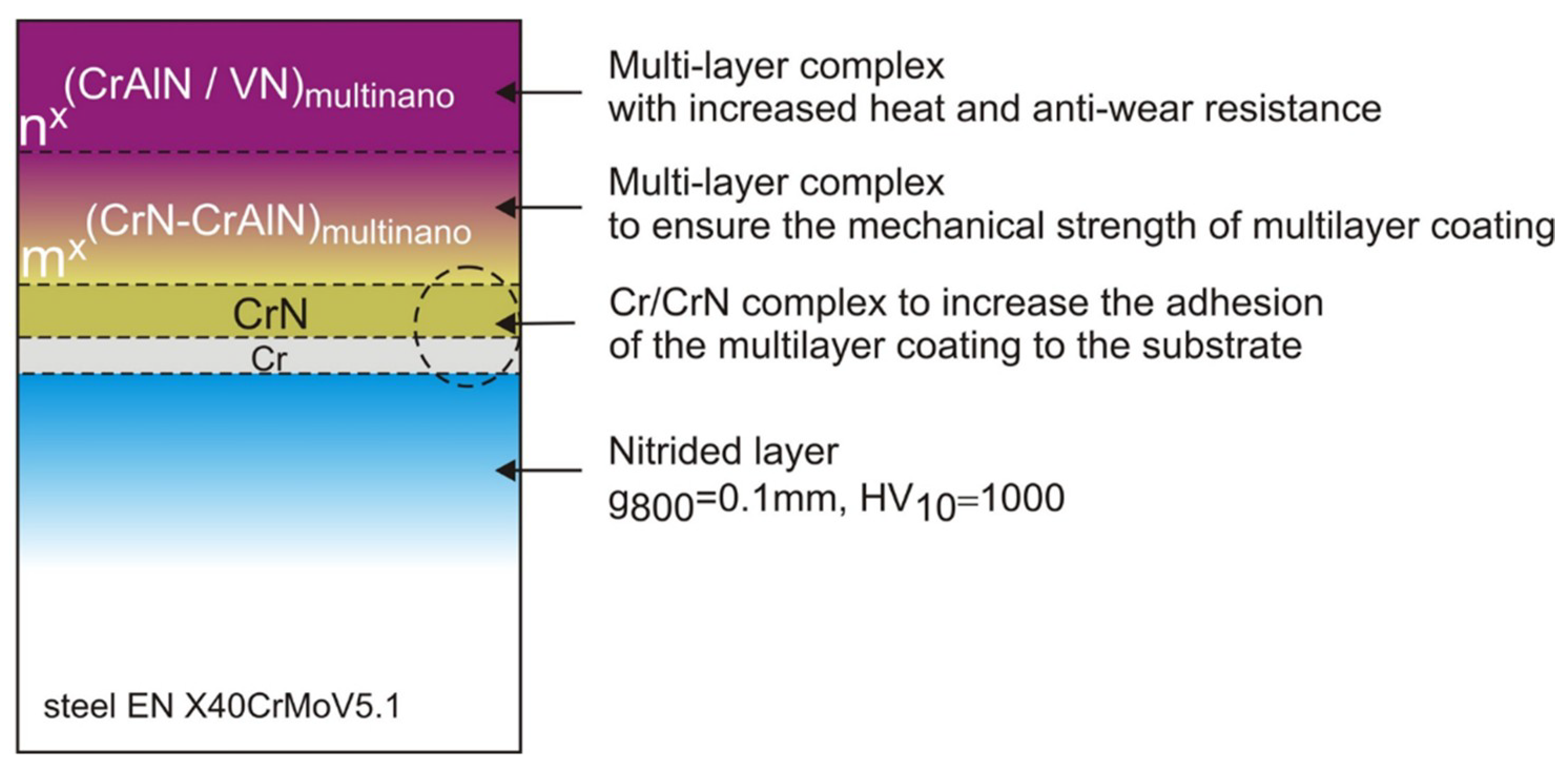
The aim of the presently described experiment was to estimate the effectiveness of a protection of the heat resistant steel through the hybrid treatment including substrate nitriding followed by arc deposition of Cr/(CrN)/nx(CrN/CrAlN)/mx(CrAlN/VN) or Cr/(CrN)/nx(CrN/TiAlN) /mx(TiAlN/VN) nano-multilayer coatings. It was realized through detailed scanning and transmission electron microscopy (SEM/TEM) microstructure characterization backed by hardness, adhesion and wear measurements.
2. Materials and Methods
The DIN 1.2344, EN X40CrMoV5.1 tool steel containing (in wt. %): C–0.39, Si–1.10, Mn–0.40, Cr–5.20, Mo–1.40, V–0.95, Fe–balance was used as a substrate for the developed coatings. The steel substrate was hot rolled at approximately 1050 °C, then annealed at 840 °C for 4 h and cooled with a furnace. Next, the complex heat treatment consisting of austenitization at 950 °C for 0.5 h and tempering at 550 °C for 2 h were conducted. The glow discharge nitriding was performed at 520 °C (
Ubias = 560–580 V,
Ibias = 7–9 A). Two types of coatings, i.e.
, Cr/(CrN)/n
x(CrN/CrAlN)/m
x(CrAlN/VN) and Cr/(CrN)/n
x(CrN/CrTiN)/ m
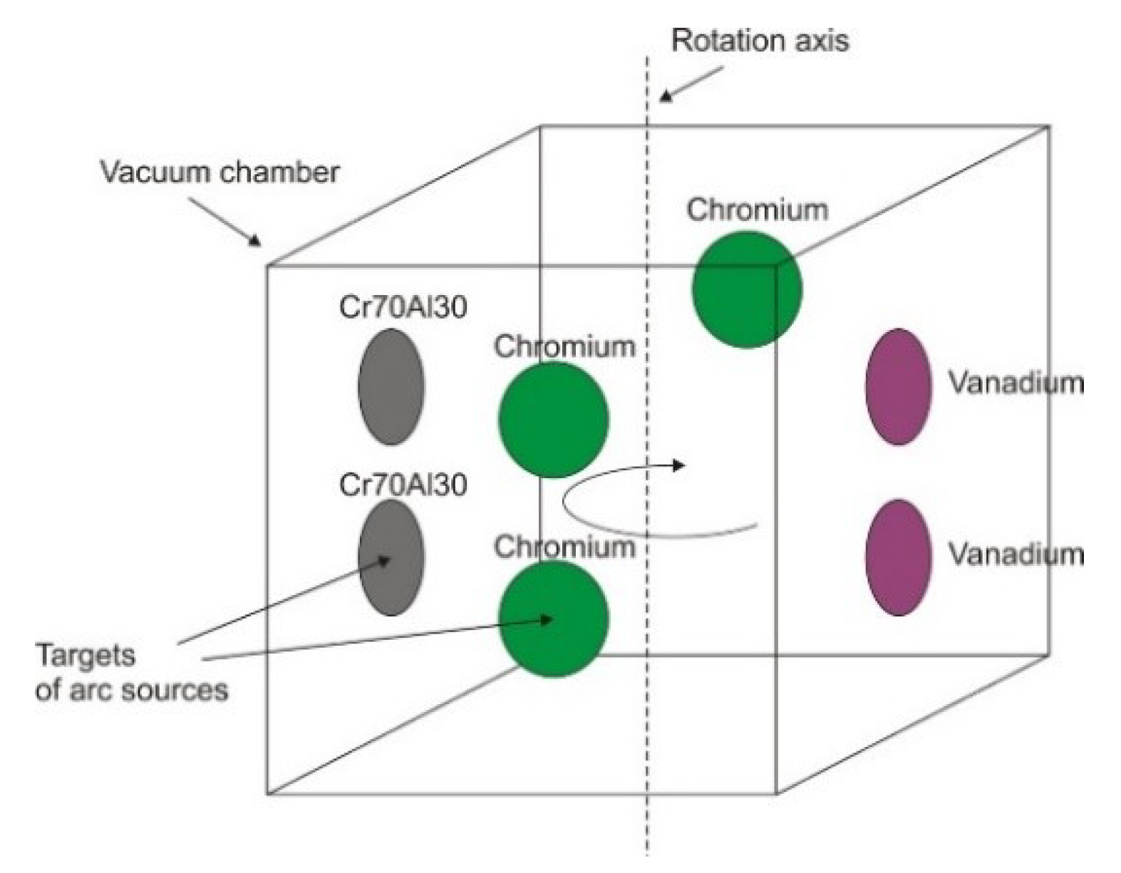
x(CrTiN-VN), assigned as P1 and P2, respectively, were deposited with a MZ383 Metaplas Ionon system. It consists of the vacuum chamber equipped with seven arc sources arranged as shown in
Figure 1. In the case of Cr/(CrN)/n
x(CrN-TiAlN)/m
x(TiAlN/VN) coatings, the Cr70Al30 targets were substituted with Ti70Al30 ones. Substrates were fixed to rotating table in a way that their surfaces were located opposite to the arc targets.
Deposition of the chromium layer was realized by activating the arc on all the chromium targets under argon atmosphere, while chromium nitride was obtained by substituting argon with nitrogen. The CrN-CrAlN stack was obtained by activating two Cr and two Cr70Al30 targets under nitrogen atmosphere and rotating the substrates at 5 rpm. Deposition of VN-CrAlN was carried out in similar way, i.e., by staying with activated discharge at Cr70Al30 targets and simultaneously switching arcs from chromium to vanadium targets. Parameters of the realized deposition process are given in
Table 1 (more details are given in [
7]).
An arrangement of the buffer layers and a sequence of the stacks of respective multilayers for the Cr/(CrN)/n
x(CrN/CrAlN)/m
x(CrAlN-VN) coating is presented in
Figure 2 (in the case of second coating the CrAlN nanolayers were substituted with CrTiN ones).
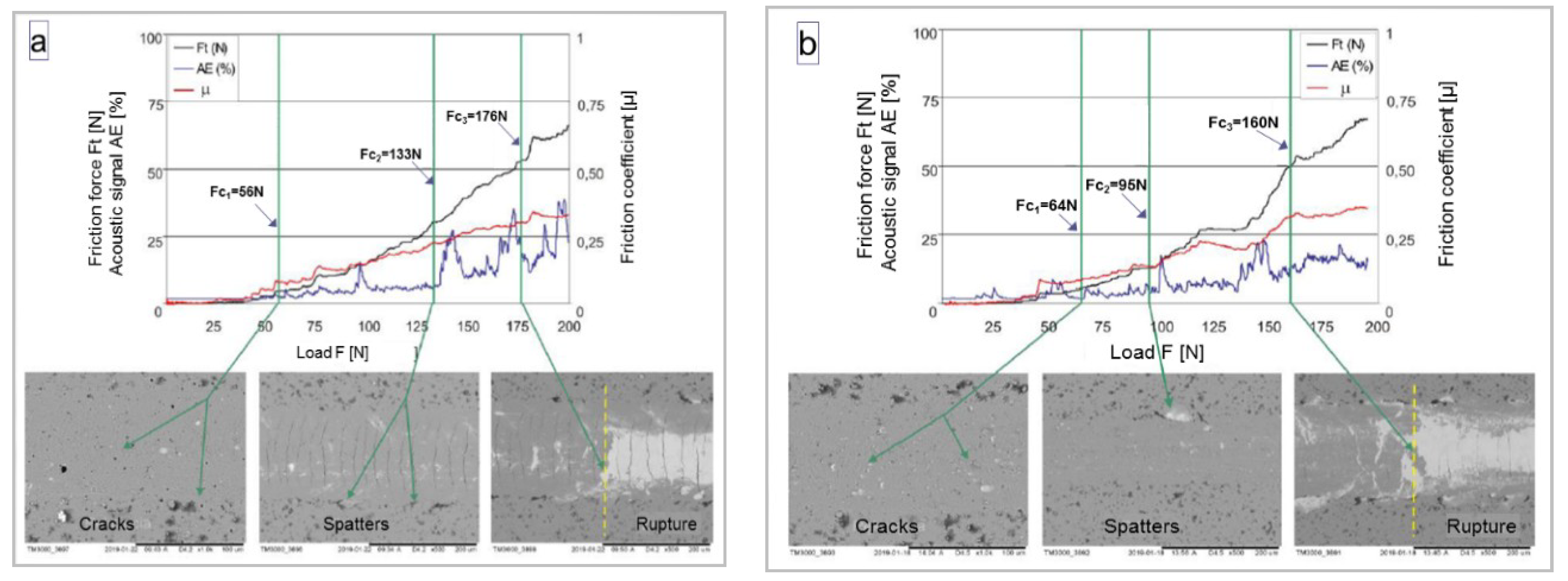
Measurements of hardness and Young modulus of the multilayer coating were performed using Berkovich indenter on NHT nanotester produced by CSM Instruments (Peuseux, Switzerland). Indentation depth was limited to ~300 nm (<30% of the coating thickness) with the aim to eliminate the effect of the substrate. The final hardness was taken as an average of up to 15 individual measurements. Adhesion was assessed in the scratch test with Rockwell penetrator (Peuseux, Switzerland) on the REVETEST CSM. The loading (from 0 to 200 N) was proportional to penetrator distance (ΔF = 10 N/mm). The start of cohesion cracks was marked as Fc1, while first delamination events were marked as Fc2. The force at which a total removal of the coating from the under the Rockwell penetrator takes place was denoted as Fc3. It was estimated basing on the sharp changes in the value of both friction coefficient and acoustic emission as well as observation of the indenter line using scanning microscopy (Hitachi TM3000, Tokyo, Japan) method.
The coatings’ microstructure was characterized using XL30 (30 kV) FEI scanning electron microscope (SEM) (FEI, Eindhoven, Netherlands) and Tecnai G2 F20 200kV FEG transmission electron microscope (Eindhoven, Netherlands). The latter was equipped with Fischione High Angle Annular Dark Field (HAADF) detector for STEM observations. The local chemical composition was determined with an integrated EDAX Energy Dispersive X-ray Spectroscope (EDS) (Berwyn, PA, USA). Thin lamellas for TEM observations were prepared using FEI Quanta 200 3D Dual Beam Focused Ion Beam (FIB) system. It involved covering coatings with a ~300 nm amorphous carbon layer serving as a buffer between them and platinum protecting stripe (1 mm wide, ~up to 20 mm long) was deposited on top of them. Next, all material at the stripe sides was removed with the Ga+ ion beam. Thus, the obtained platelet was lifted out with the Omniprobe attachment and welded to FIB copper grid. Finally, the platelet was thinned down to ~100 nm with Ga+ ions producing a lamella presenting the multilayer coating in a cross-section.
3. Results
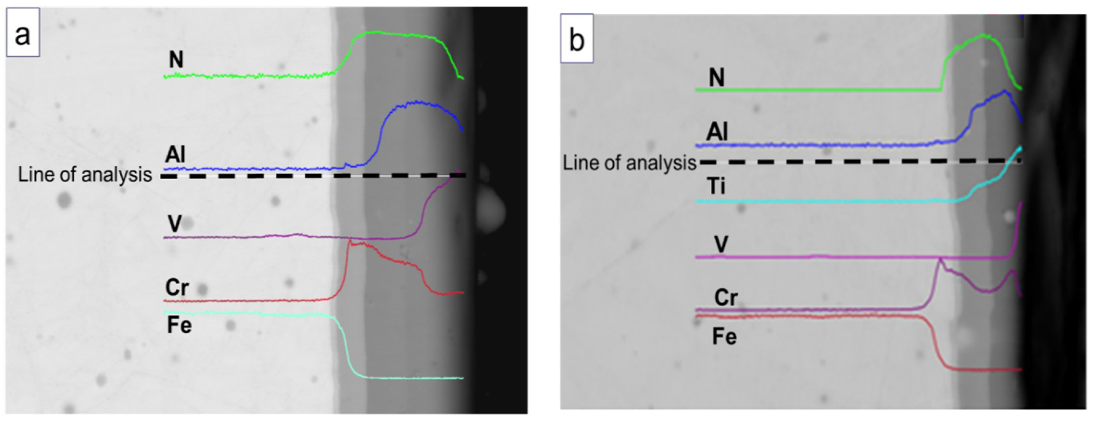
The SEM image acquired in Back Scattered Electrons (BSE) mode presenting cross-section of the hybrid processed tool steel, i.e., a nitrided base material covered with multilayer protective coatings, showed that deposition of the Cr/CrN buffer double layer secured formation of a non-porous interface between them (
Figure 3). The SEM/EDS profiles documenting distribution of elements across the Cr/(CrN)/n
x(CrN/CrAlN)/m
x(CrAlN/VN) coating confirms stepped decrease of Cr concentration from bottom to top as well as partial substitution of Al with V in the near surface area (
Figure 3a). The EDS profile obtained from Cr/(CrN)/n
x(CrN/TiAlN)/m
x(TiAlN/VN) coating shows roughly the same stepped relation as it concerns the diminishing concentration of Cr (raised Cr intensity is an artifact due to superposition of Cr-Kα with V-Kβ lines) as well as raising concentration of V in the near-surface area (
Figure 3b). The surface of the multilayers was found to be decorated with droplets of sizes starting from tens of nanometers and ending in micrometer range.
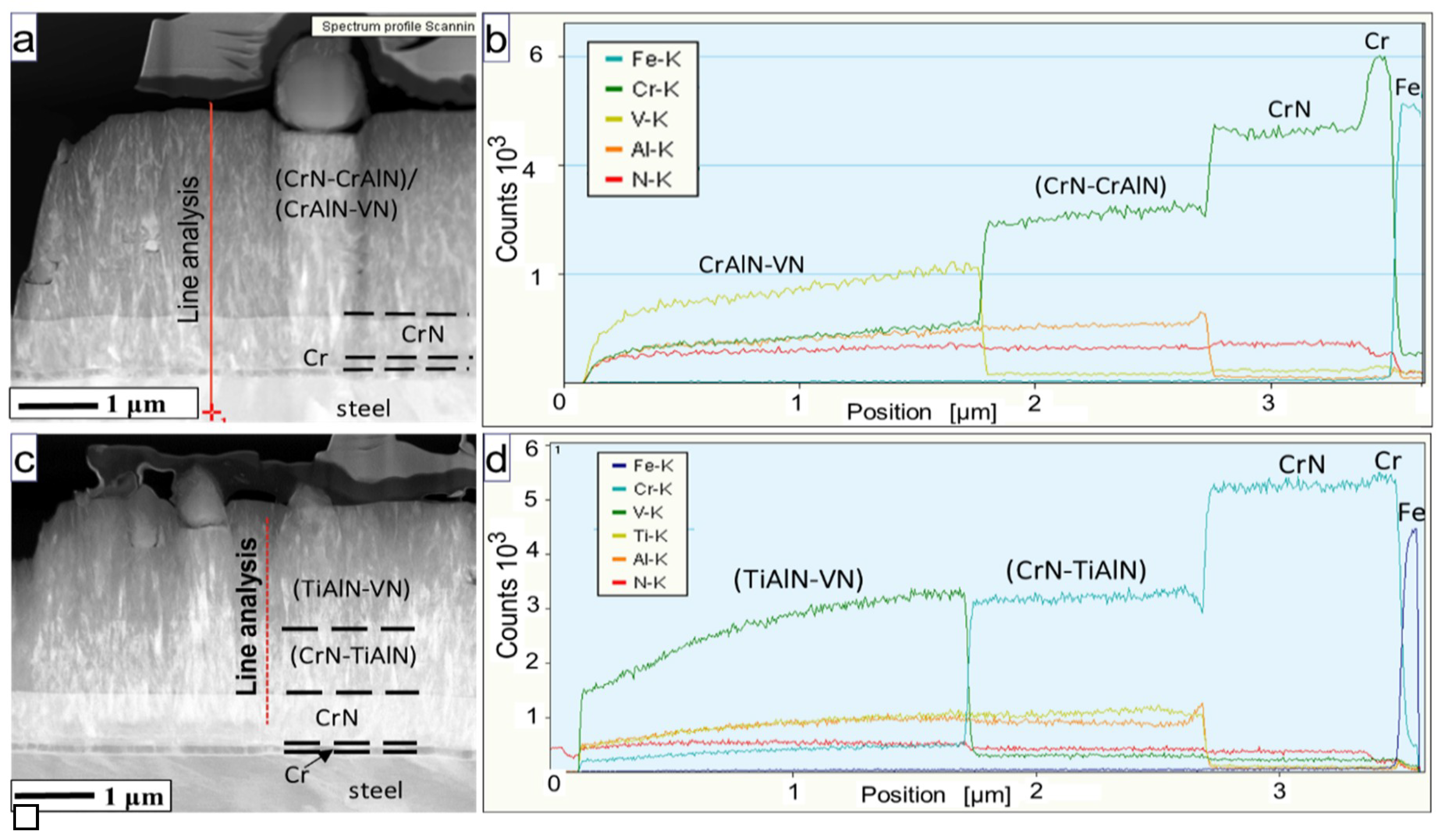
The STEM/HAADF microstructure images helped to establish that coatings are built of pseudo-columnar grains and the droplets observed previously on the coatings surface are also present within them (
Figure 4a,c). The EDS profiles are characterized by lowering number of acquired counts when approaching the surface of the coating due to reduced thickness of the TEM lamellas in such areas (
Figure 4b,d). The EDS signal acquired from the Cr/(CrN)/n
x(CrN/CrAlN)/m
x(CrAlN/VN) coating documented high chromium concentration in the first buffer layer and its lowering in CrN and the following stacks of nitride/nitride multilayers (
Figure 4b). In the case of the Cr/(CrN)/n
x(CrN-TiAlN)/m
x(TiAlN-VN) multilayer the situation is similar with an exception of much smaller difference between counts from Cr and CrN caused by oversaturation of the EDS detector due to large foil thickness. Simultaneously, the diminishing concentration of chromium is substituted first by aluminum starting at the middle of the multilayer and, later, also by vanadium located closer to the surface parts. The activation of the aluminum arc target is accompanied by a strong local enrichment of multilayer in this element, i.e., its concentration rises above the average for the CrN/CrAlN or CrN/TiAlN stack. However, a switching on of Ti or V targets proceeds through gradual approaching to the average concentration of the involved elements. As it took place during SEM/EDS measurements, the presence of a false chromium signal within the most top TiAlN/VN results from a superposition of vanadium and chromium lines, i.e., V-Kβ is taken for Cr-Kα (
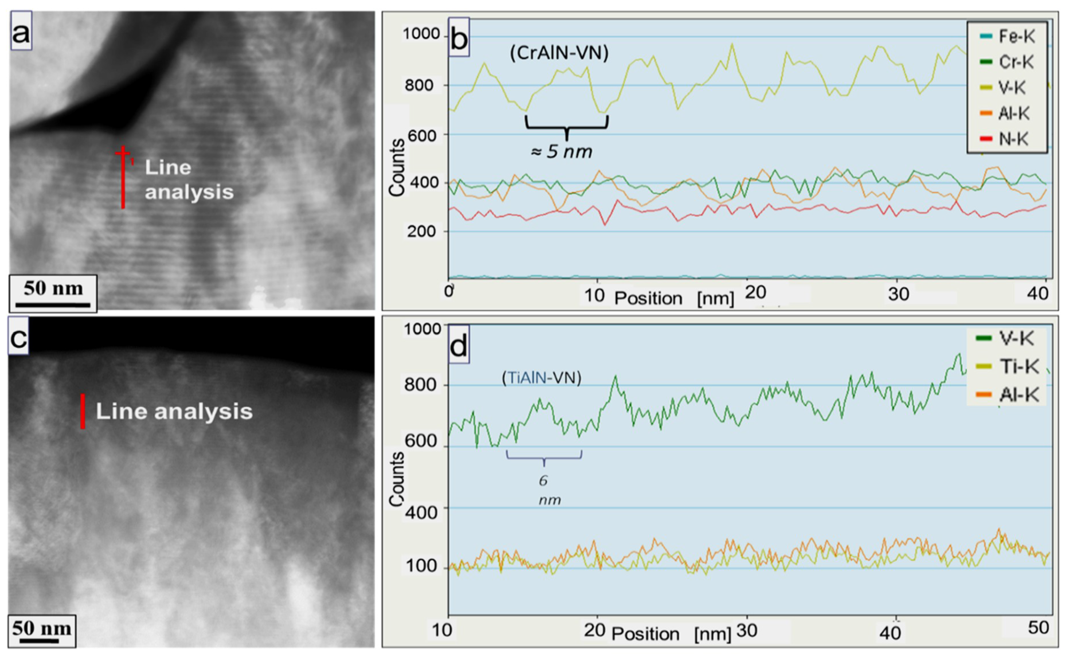
Figure 4d). The STEM/EDS profiles obtained at higher spatial resolution from the near-surface area helped to differentiate the multilayer character of this coating using vanadium signal (
Figure 5). The complementary changes of Al and Ti concentration were weaker but still evident, while changes in Cr in that area were too noisy to ascribe them to any specific set of nanolayers (the same situation was with the signal from nitrogen, which was therefore omitted from both graphs). The contrast variation seen in STEM/HAADF images and the changes in STEM/EDS signal strength helped to determine the characteristic parameter of the coatings as given in
Table 2.
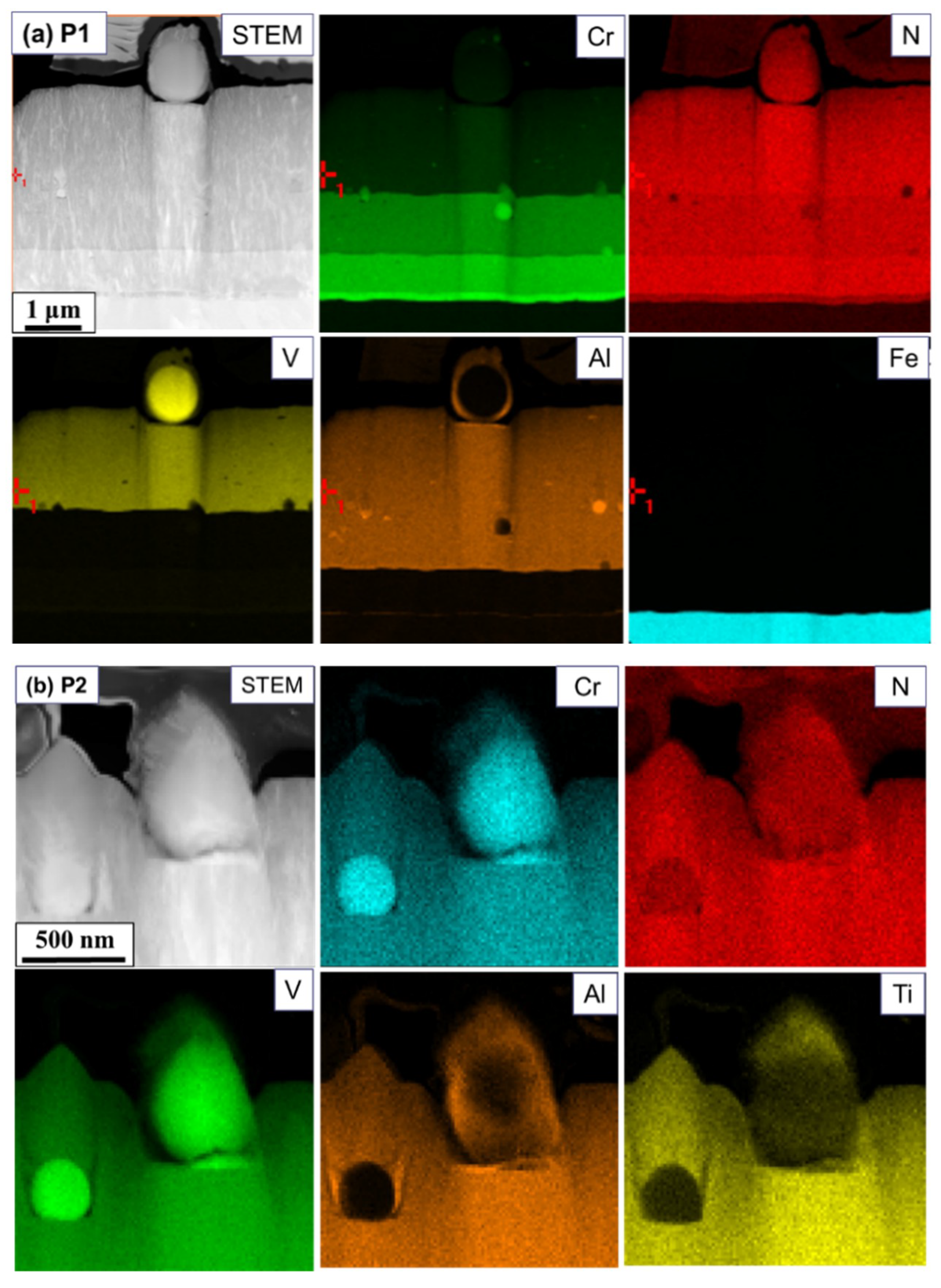
STEM/EDS maps with local distribution of coating forming elements indicated that the deposition of droplets takes place during the growth of all successive parts of the coatings, i.e., they bear Cr, Al, Ti and V ones. However, the biggest droplets were found to be built of vanadium (
Figure 6).
The mechanical testing of deposited coatings helped to established that they both present nearly the same hardness of 25.0 ÷ 26.0 GPa (
Table 3). However, the P2 was characterized by ~10% higher stiffness over the P1, i.e., with the average value of the Young modulus E of 400 and 370 GPa for the former and the latter, respectively.
Results of scratch tests of the P1 and P2 coatings are presented in the
Figure 7. The SEM observations of the path covered by Rockwell indenter helped to establish that in both coatings the first microcracks denoted as the Fc
1 show up at a distance corresponding to ~60 N. Up to that loading, also the friction coefficient remains practically negligible for both coatings. The measurements of accompanying acoustic emission from the P2 coating gave couple of sound pulses clearly above the noise level indicating that in this case the value of Fc
1 could be half of this determined through SEM observations. Applying the force exceeding 60 N caused a development of series of evident adhesive cracks accompanying by steadily raising friction coefficient as well as a series of acoustic emission pulses of medium strength in both the P1and P2 coatings. Only after the load on the indenter reached the values of ~130 N or ~100 N for the P1 and P2 coating, respectively, the scratch path showed first signs of removal of small parts of the coatings visibly, both at the bottom of the indenter path and at their edges (the value of the second critical force is marked as Fc
2). The above processes continue till the 160–170 N at which a total removal of the coating from under the indenter starts, followed by a steep raise in friction force as well as multiple strong acoustic pulses.
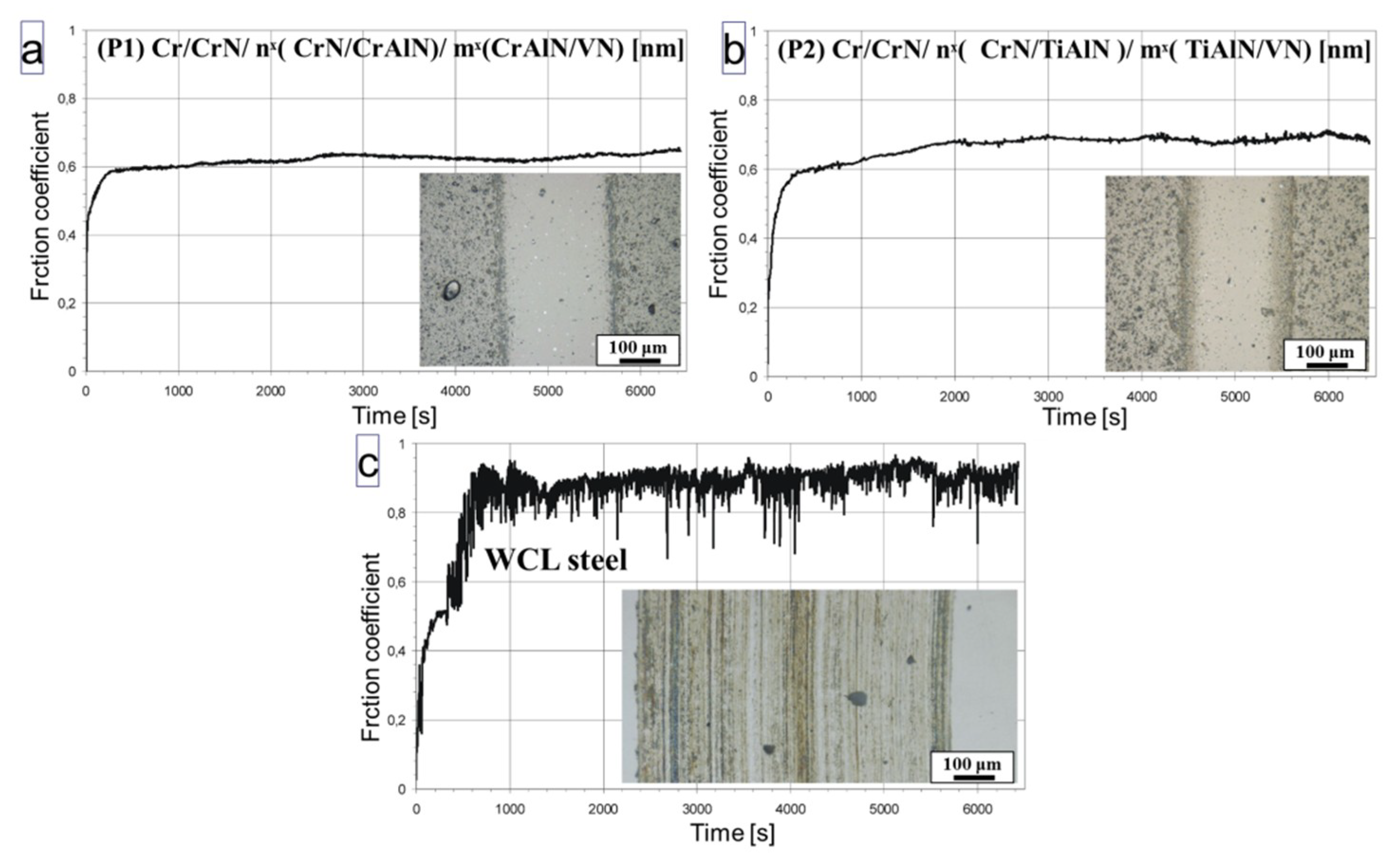
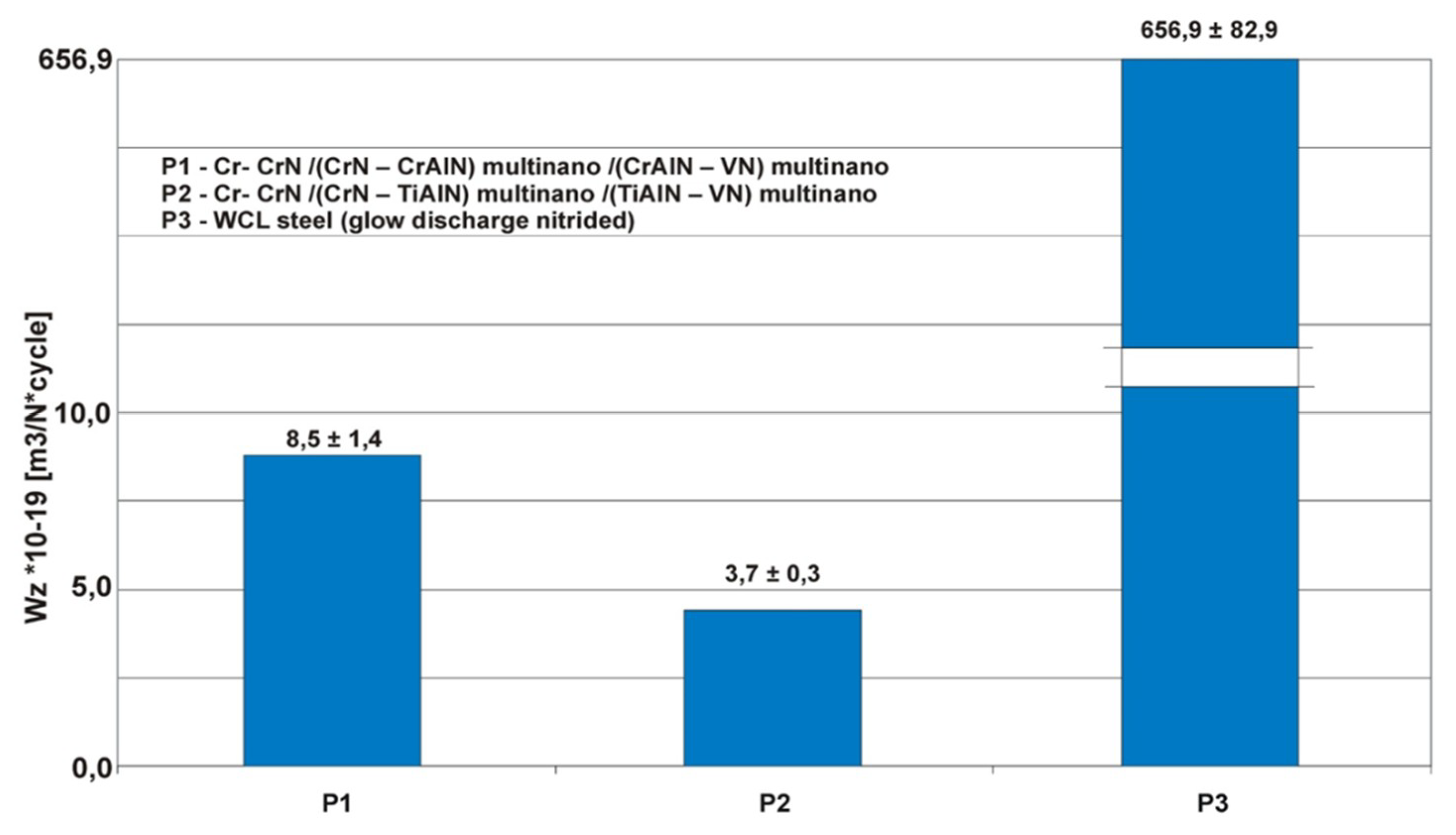
The wear test of the P1 and P2 multilayer coatings, done in a ball-on disc stand at ambient temperature, showed that the tracks forming as a result of ball action have smooth edges, sides and bottom (
Figure 8). The brighter spots within the wear track represent droplets cut by the passing ball, while the darker ones represent holes left by broken out droplets. The friction coefficients are similar for both coatings, even if this for the P2 coating was slightly higher than for P1 throughout most of the test, i.e., ~0.7 against ~0.6, respectively. The wear track on reference nitrided WCL steel was not only significantly wider after comparable times, but also bears the marks of deep groves along it. As a consequence of the above, the friction coefficient measured for this sample was not only the highest but also showed frequent instabilities. The quantitative assessment of the wear test helped to establish that, as compared with the reference plasma nitrided tool steel, the P1 and P2 multilayer coatings present ~100 times and ~200 times better wear resistance, respectively (
Figure 9).
4. Discussion
Reactive arc plasma sputtering of monolithic chromium, vanadium or sintered alloy targets like CrAl or TiAl at substrates rotating in front of them, as in the present experiment, allows us to obtain the stacks of alternating nitride/nitride nanolayers of the total thickness of a few micrometers, placing it among the most potent PVD methods. The high capability of this method in the deposition of hard coatings was documented in the past with the production of nanoperiod nitride/metallic and nitride/nitride multilayers by Wiecinski et al. [
10] and Chen et al
. [
11], respectively. The so much prized high deposition rate of the arc-plasma method is, however, tarnished by the unavoidable presence of droplets—as long as one wants to stay with the high deposition rate available with this method—exceeding the nano-multilayer period and intermixing of the deposited material.
The arc droplets compromise the multilayers’ geometry, increasing the surface roughness as well as overshadowing their surroundings and blocking of an in-flow of a new material in this area. The latter situation leads to formation of voids, which under stress could act as crack nucleation sites. The EDS measurements of nanolayers’ chemical composition pointed to a strong intermixing of material coming from different targets at their interfaces. It falls down away from them, but in the case of multilayer periods <10 nm it is still significant even in centers of the individual layers (as documented in
Figure 4). The intermixing experimentally determined through EDS measurements is definitely strongly overestimated by unavoidable probe broadening in the specimen (~100 nm thick), but more precise measurements with atom probe tomography of PVD CoFe/Cu/CoFe/Ni nanolayers [
12] indicated the presence of gradient composition extending up to 2 nanometers. Chang et al
. [
11] showed that the fcc-nitride/fcc-nitride multilayer interfaces are at least locally coherent, what explains a raise in hardness with the lowering of the multilayer period. However, the presence of intermixing of deposited material relieving stresses at such boundaries places a natural limit on their period of ~10 nm, below which no more gains in multilayer hardness are possible.
The local chemical composition, analyzed through a 2D mapping with EDS method, showed that the arc temperature is so high that the discussed droplets are ejected from both elemental and alloyed targets at approximately same rate independently from the strong difference between their melting temperature. Additionally, switching on the CrAl or TiAl targets results in short (extending up to 20 periods of CrN/CrAlN nanolayers) but relatively strong enrichment in aluminum of respective alloyed nitride layers (50% above the nominal). It is significant that somewhat similar activation of still another target later on, i.e., taking place during substitution of the Cr target with the V one, starting with the deposition of VN/CrAlN nano-multilayer allows us to deposit the material of designed chemical composition from the very beginning. The above may only mean that the CrAl or AlTi targets compacted from the elemental powders carry higher surface content of the aluminum oxide. During the start of the arc this surface material is the first to be transferred to the substrates causing the observed local enrichments in aluminum or titanium. But in such a case these parts of multilayers will have to be enriched in the oxygen. Its absence at the acquired spectra results just from the high absorption of this relatively soft X-ray radiation by metallic atoms in the thick FIB specimen.
Hardness measurements of monolithic bi-metallic nitride CrAlN arc coatings were found to be significantly (by ~30%) harder than CrN ones, i.e., achieving close to 23 GPa, but partial substitution of Cr with V (being of high interest as its oxide forms an excellent solid lubricant) has practically no effect on it [
13]. Magnetron deposition of metal-nitride/metal-nitride stacks, like in case of the TiAlN/CrN system as shown by Barshilia et al
. in 2005 [
14], turned out more effective than simple alloying of chromium nitride, as they presented hardness as high as ~38 GPa for the multilayer period of ~7 nm. Later experiments done by Chen et al
. [
9] showed that also the arc CrN/CrAlN/ (CrAlN/AlTiSiN) multilayer coatings could achieve comparable high hardness (~35 GPa) as long as a proper bias voltage sieving away at least part of droplets will be applied. Merging the knowledge from these experiments opened a field for development of coatings with bi-metallic multilayer nitrides from the Cr-Al-Ti-V system. As a consequence, the hardness of 38 GPa was achieved for AlCrN/TiVN (λ~14 nm) arc multilayers [
11]. The lower hardness (25–26 GPa) of the presently arc deposited stacks of nitrides with CrAlN/VN or TiAlN/VN at their top (elaborated within the present experiment) means that even the nano-multilayer engineering cannot make up for hardness loss due to introduction of relatively soft VN nitride.
Wear of materials protected by the coatings mostly depends on their adhesion and hardness as well as the type of wear debris. The latter could, under special conditions, serve as an additional solid lubricant. Therefore, the progress in this area is gained through development of the coatings characterized by improved micromechanical properties but also containing material lowering the friction. In this application the most popular is vanadium, as at higher temperatures and in the presence of oxygen from the atmosphere it turns into easily shearable vanadium oxide particles. Uchida et al
. [
13] showed that the wear of softer monolithic CrVN coating on AiSi52100 steel is four times lower (even more on cemented carbide substrates) than that of the much harder CrAlN. The first experiments with CrAlN/VN multilayer coatings (λ~20 nm) brought less spectacular, but also significant gains in wear resistance, i.e.
, improvement by nearly two times was achieved [
15]. The following experiments on arc AlCrN/TiN multilayers coatings (λ~14 nm) deposited on WC-Co substrates also gave roughly two times higher wear resistance [
11]. The combination of stacks of hard multilayer nitrides covered with stack of only slightly softer but bearing mono-metallic VN layers (in both case with λ < 10 nm) on nitrided X40CrMoV5 steel elaborated throughout the present experiment again helped to obtain very high increase in wear resistance, i.e.
, from 100 to 200 times, over the nitrided WCL reference material. The above success should be partly attributed to a deposition of vanadium carrying multilayers of very low period what helped to preserve the overall hardness of this coatings exceeding those proper for monolithic CrN. The other parameter contributing toward the low wear must have been the nitriding of the WCL steel substrate, which gave the coating a proper support and adhesion through the intermediate Cr/CrN bi-layer buffer.


