Review

Thermionic Vacuum Arc—A Versatile Technology for Thin Film Deposition and Its Applications

1
Department of Physics, Faculty of Applied Sciences and Engineering, Ovidius University, Mamaia bd. 124, 900527 Constanţa, Romania
2
Faculty of Mathematics and Physics, Charles University, Ke Karlovu 3, 121 16 Praha 2, Czech Republic
*
Author to whom correspondence should be addressed.
Coatings 2020, 10(3), 211; https://doi.org/10.3390/coatings10030211
Submission received: 31 January 2020 / Revised: 20 February 2020 / Accepted: 25 February 2020 / Published: 27 February 2020
(This article belongs to the Special Issue Thin Film Coatings for Multifunctional Applications)

Abstract

:
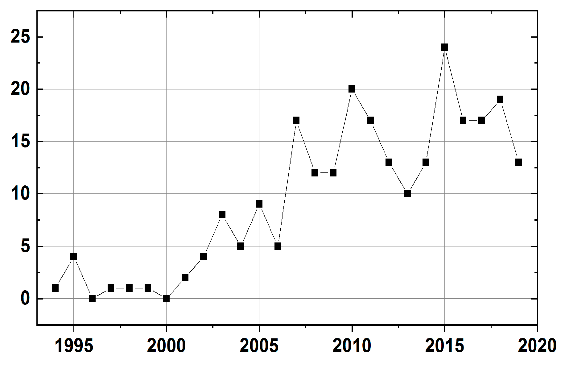
This review summarizes the more-than-25-years of development of the so-called thermionic vacuum arc (TVA). TVA is an anodic arc discharge in vapors of the material to be deposited; the energy for its melting is delivered by means of a focused electron beam. The resulting material ions fall at the substrate where they form a well-adhesive layer; the ion energy is controllable. The deposited layers are, as a rule, free from droplets typical for cathodic arc deposition systems and the thermal stress of the substrates being coated is low. TVA is especially suitable for processing refractory metals, e.g., carbon or tungsten, however, in the course of time, various useful applications of this system originated. They include layers for fusion application, hard coatings, low-friction coatings, biomedical-applicable films, materials for optoelectronics, and for solid-state batteries. Apart from the diagnostic of the film properties, also the diagnostic of the TVA discharge itself as well as of the by TVA generated plasma was performed. The research and application of the TVA proceeds in broad international collaboration. At present, the TVA technology has found its firm place among the different procedures for thin film deposition.

1. Introduction

The vacuum arc is commonly considered as a high-current, low-voltage electrical discharge, which produces a plasma consisting of vaporized and ionized electrode material. In [1] the arc is defined as “a discharge in a gas or vapor that has a voltage drop at the cathode of the order of the minimum ionizing or minimum exciting potential of the gas or vapor”. Further definition found in [2] characterizes arc as “a self-sustained discharge capable of supporting large currents by providing its own mechanism of electron emission from the negative electrode”. As pointed out in [2], the term “vacuum arc” is contradictory: if there is an arc there is no vacuum, and where vacuum is there is no arc. The term “vacuum arc” implies therefore that there was vacuum between electrodes before and after the arc discharge. Traditionally, “vacuum arc” is used to emphasize the absence of any significant gas pressure before the discharge [3].
The aim of this review is to introduce a versatile nanofabrication method based on plasma entitled thermionic vacuum arc (TVA). This consists of an externally heated cathode surrounded by a Wehnelt cylinder that concentrates by a high voltage accelerated electrons on the anode material. Due to the electron beam power, continuous evaporating of the anode material takes place and ensures its vapor density in steady state. When a certain vapor density is achieved, the applied high voltage ignites and maintains a bright discharge in the inter-electrodes space. The discharge sustaining gas is just the evaporating atoms in vacuum, therefore the thin film deposition is made in high purity conditions.
Vacuum arc plasma deposition is one of the oldest and, simultaneously, one of the most modern, emerging technologies, see e.g., [4]. The aim of this paper is to illustrate that by the samples of the relevant research in broad period: from the fifties in the last century until the present time. While most of the applications have been realized with the cathodic vacuum arc we turn our attention to the anodic vacuum arc, especially to its specific version called the thermionic vacuum arc.
As inventors of the vacuum arc deposition methods are usually quoted the U.S. patents filed by Snaper A. A or by Sablev L.P. [5,6]. However, the application of a vacuum arc for deposition of thin films of refractory metals begun a lot earlier. Already in 1954 there was published a paper where he used a vacuum arc for deposition of carbon thin film [7]. The widespread applications have been achieved with a cathodic vacuum arc. The cathodic arc plasmas are fully ionized with very energetic ions, promoting adhesion and the formation of dense films. The main disadvantage of the cathodic vacuum arc consists in creating macroparticles that deteriorate the properties of the deposited film. In addition, films may be under high compressive stress. In the sixties and seventies of the last century, the cathodic vacuum arc technology became intensively investigated and applied in Soviet Union, see e.g., [8,9]. In order to get rid of the macroparticles ingenious filters have been constructed, e.g., in [10] or [11]. Several books about the vacuum arc deposition have been published later, e.g., [1,2,12,13]. The books on the vacuum arc were revised and re-published several times that documents interest of the scientific community in this technology.
The anode of an arc discharge does not always have to be a passive electron collector but may emit vapor that then becomes a plasma; that phenomenon is called the anodic vacuum arc. That phenomenon is mentioned as hot anode vacuum arc (HAVA) or hot refractory anode vacuum arc (HRAVA) in [14]. It is noted there that these modes, rather than “conventional cathodic arc” can eliminate or greatly reduce the macroparticles production. In the present article, we focus on the anodic vacuum arc type of discharge, especially on its modification called TVA.
To our knowledge, the first paper related to the phenomenon of the anodic vacuum arc, was [15]. As sometimes happens in science, this discovery was, from their point of view, an unexpected finding that later became known as so-called sustained self-sputtering. They run an argon arc discharge supported by a hot tungsten filament that was positioned above a crucible with materials; in their case, the materials were Fe–V and Fe–Ni alloys. When they increased the discharge/arc current above a certain level, they realized that the materials in the crucible melted. Consequently, the argon gas that formerly supported the arc discharge was no longer necessary, and the arc could burn in vapors of the material to be deposited. The novelty of their finding resided in the fact that the crucible represented the anode of the discharge, and that the anode material was heated by an electron swarm; not by an electron beam.
In ref. [16] is described a new type of vacuum arc, in which the auto-generation of the medium occurred exclusively because of evaporation of the anode. The anode was heated by an electron beam that was created by a hollow cathode. It was concluded that this vacuum arc may find applications for producing high-density atomic plasma of solid materials.
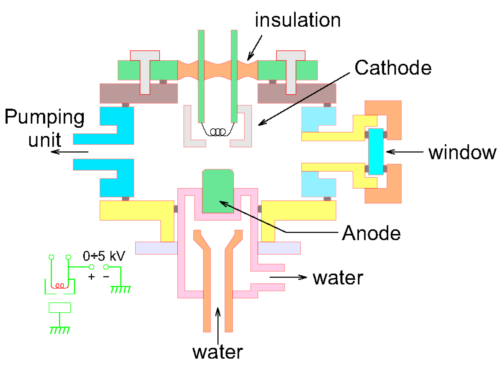
Electron beam heating sources have been exploited for thermal evaporation (PVD) of refractory metals since 1965, see e.g., [17,18,19]. Apart from using an electron beam for process of thermal evaporation of refractory metals, these authors describe also so-called reactive evaporation process when the reacting gas neutral molecules are activated by passing them through a glow discharge or microwave discharge prior to the gas being released into the reaction zone, i.e., the space between the source and the substrate. Closer to the anodic vacuum arc was already the process of so-called activated reactive evaporation [17], see Figure 1. It uses the phenomenon that the molten target material, heated by a high acceleration-voltage electron beam, has a plasma sheath on the top. An auxiliary electrode placed above the target is biased to a low positive dc potential 20–100 V. The low-energy secondary electrons from the plasma sheath are then pulled upwards into the reaction zone. These electrons ionize and/or activate the metal and reaction gas atoms and increase the reaction probability on collision. TiC films by reaction of Ti target molten by an electron beam and C2H2 gas atoms were achieved by this process. The method obtained a U.S. patent, [20]. However, this process cannot be called, in our opinion, as an anodic vacuum arc yet.
The genuine anodic vacuum arc was treated in detail by one of the researchers that later cooperated with the invention of the TVA, H. Ehrich. He published four relevant papers, namely [21,22,23,24] at the end of nineties. In the first paper, he described the construction of the discharge electrodes: the W cathode and the anode e.g., in form of a W crucible filled with the respective material; in his case Al. In order to ignite the arc discharge, the electrodes had to be shortly contacted. Alternatively, a low pressure of Ar, around 100 Pa, was introduced at the beginning of the process that was turned off afterwards. He found that the Al metallic coatings produced by means of the anodic vacuum arc showed promising features: the coatings were homogeneous, the deposition rates were comparatively high (8 nm/s for a 0.7 kW Al arc), and the thermal stress of the substrates being coated was low. In ref. [22] an experimental study of the anodic arc plasma was performed. Spectroscopic investigations of the interelectrodic plasma showed that the discharge was totally sustained by evaporated anode material. Additionally, that the evaporating part of the anode was a source of a metal plasma with a high degree of ionization; between 4% and 20% of the atoms arriving at the surface of a substrate were ionized. The surface temperature at the anode was far above the melting point of the consumed material. The expanding metal vapor plasma from the anode was investigated at distances of 0.12 and 0.24 m from the anode for the metals Al, Cr, and Ti; electron densities in the order of 1016 m−3 and electron temperatures between 0.2 and 1.0 eV were determined. Deposition rates ranged from 1 to 50 nm/s. In ref. [23,24] the findings about the anodic vacuum arc and its application to coating were summarized. The method obtained a U.S. patent [25].
The diffusion theory of the low-voltage arc plasma has been presented by [26]. Studies on a vacuum arc discharge with an evaporating anode and a thermionic cathode using an electrostatic field to focus the electron beam onto the anode have been, however, for the first time published in 1983 in [27]. In this paper, a discharge similar to the low voltage arc has been observed in metal vapors during the experiments on the electron beam welding in high vacuum using a simplified electron gun, mounted at a small distance from the pieces to be welded. In ref. [28] the electrical (I-V characteristic) and spectral characteristics of a heated cathode discharge in vapors of Ti and Cu have been studied. The schematic diagram of the apparatus is shown in Figure 2. The electron beam focused by Wehnelt cylinder produced a melted spot on the anode material and the spectroscopy proved that the discharge burns in the vapors of the anode material. In ref. [29] there was suggested to apply heated cathode discharge in anode vapors for high-power copper laser construction. For the first time the pulse-operation of this type of discharge in Cu vapors, needed for the prolonged laser operation, was discussed, realized and diagnosed. The pulsed operation of a hot-cathode discharge in copper vapors from a melted anode was investigated also in ref. [30]. A similar anodic arc discharge was applied to deposition of protective layers inside tubes [31].
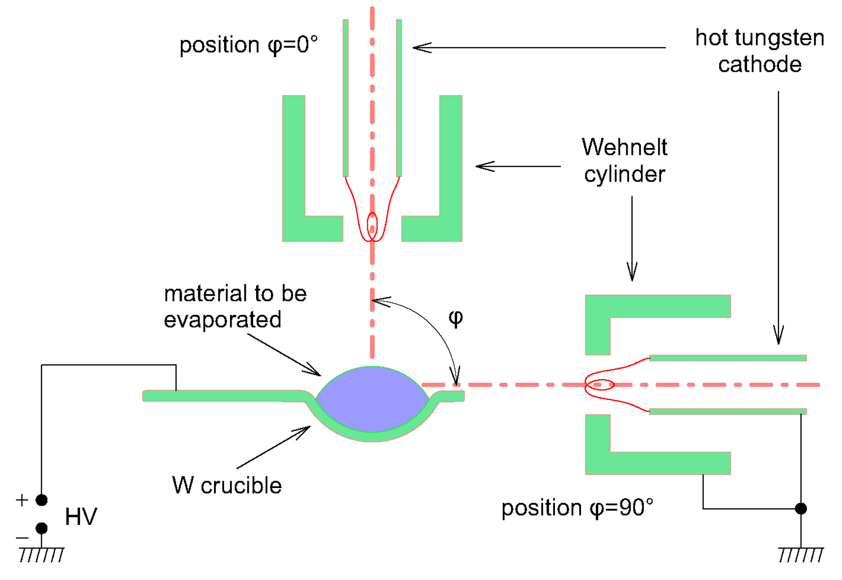
In ref. [32] the authors performed the more-detailed studies that used a focused electron beam for heating material of a vacuum arc anode. The authors investigated vacuum arc discharges with evaporating anodes that exploited the directly as well as indirectly heated cathodes. The principle construction is depicted in Figure 3. We see the hot cathode, directly heated, that emits a swarm of electrons. The electrons are then focused by the Wehnelt cylinder into a beam with a cross-section around 4 mm2. That beam is directed onto an anode in form of a tungsten crucible containing the material to be deposited at an angle φ. The I–V characteristics of the discharge were measured for different inter-electrode distance, different cathode heating current and different guiding angles φ for the anode made of Cu, Al, and Zn. For the first time also the Langmuir probe diagnostic of the expanding plasma has been performed yielding the plasma potential of the order 100 V, electron temperature around 10 eV and electron density around 5 × 10¹⁵ m−3. That corresponded roughly to the degree of ionization between 1–6 × 10⁻². The discharge had a similar behavior as a low-voltage arc; thus, the authors introduced the name “thermionic cathode vacuum arc”. In order to remove the possible confusion with the cathodic vacuum arc the name was later shortened to TVA, thermionic vacuum arc; sometimes spelled as “thermoionic vacuum arc”.
The energy of ions generated by a TVA discharge, which is a decisive parameter for reaching good quality of deposited films, has been measured in ref. [33]. These studies revealed the possibility of adjusting the energy of the ions even during deposition by changing only a few specific working parameters. The work concludes further that nearly every metal vapor plasma can be generated by the TVA plasma source.
Advantages of the TVA system are summarized in [34]. They are as follows: (i) extended application possibilities for the increase of the microhardness of the pieces, (ii) decrease of the friction of moving pieces, (iii) change of the chemical reactivity of the pieces (corrosion-resistant components), (iv) possibility to develop the nanostructural materials. As a disadvantage of this system some authors quote the rather short time of the tungsten filament, especially in cases with boron deposition. The limited amount of the material in the crucible may also present a restriction. In some cases, the discharge may be unstable, which creates (surmountable) problems with plasma diagnostic.
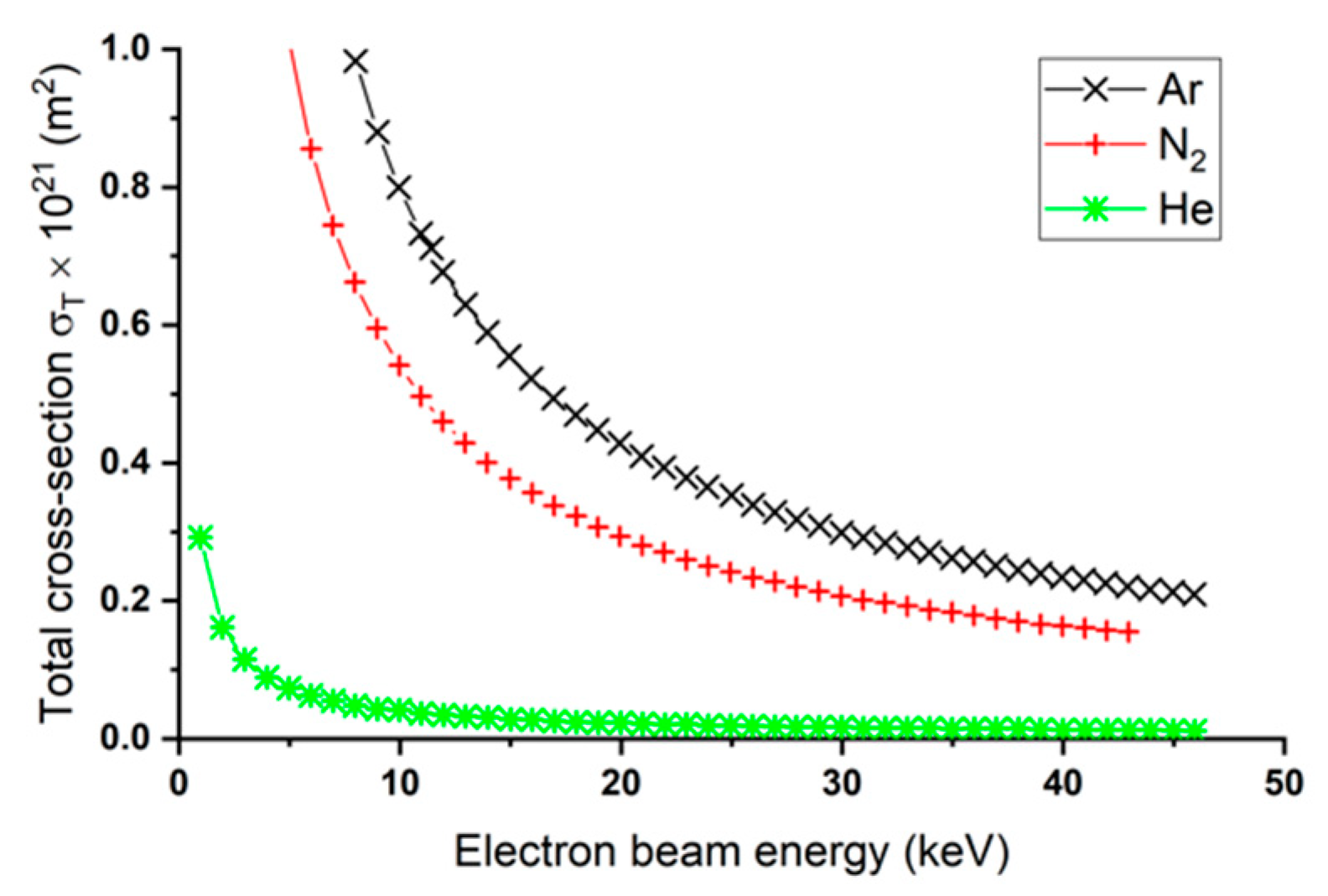
The physics of the discharge ignition in a TVA system is itself an interesting problem. The former papers describing the TVA just show the abrupt change in an I-V characteristic of the discharge when the discharge ignites, however, they do not describe the actual physical mechanism. The sentence “If the interelectrode gap is sufficiently small, the vapor density between the electrodes is high enough to ignite and sustain a vacuum arc discharge“ found in ref. [32] suggests a volume interaction between the vapor particles and the electron beam. Nevertheless, the pressure inside a TVA chamber when the arc is running is so low that the atoms and ions of the anode material reach the substrate almost without collisions with neutrals. A question therefore appears how the electrons in the electron beam can efficiently ionize the neutral gas in a volume considering that the mean free path for electrons is much higher than that for atoms. In order to find the answer we have to look more deeply at the inelastic cross section for the interaction of an electron accelerated at several kVs with a neutral particle. At such energies, the wave-like nature of an electron has to be taken into account. In ref. [35] the authors calculated the dependence of the total cross section for the interaction of an electron beam with three different neutral particles, see Figure 4. The sharp rise of the total cross section at lower beam energies suggests that at the energies around 3–4 keV, used in TVA systems, the volume ionization is not excluded. On the other hand, the suggestion in ref. [12], namely that the plasma is first created on the top of the melted anode material may be closer to the truth. Only simulations of the plasma ignition process in a TVA system might enlighten the problem.
The TVA technology has been studied and successfully used for the synthesis of a large range of metals, oxides and carbon. That is proved by published papers, patents and internationally funded projects. Nowadays the TVA method has been perfected to an affordable, versatile, and dependable method for obtaining multi-material processing like alloy/composite thin films at a nanometric scale for wide range of applications.

2. Arrangements of the TVA Systems

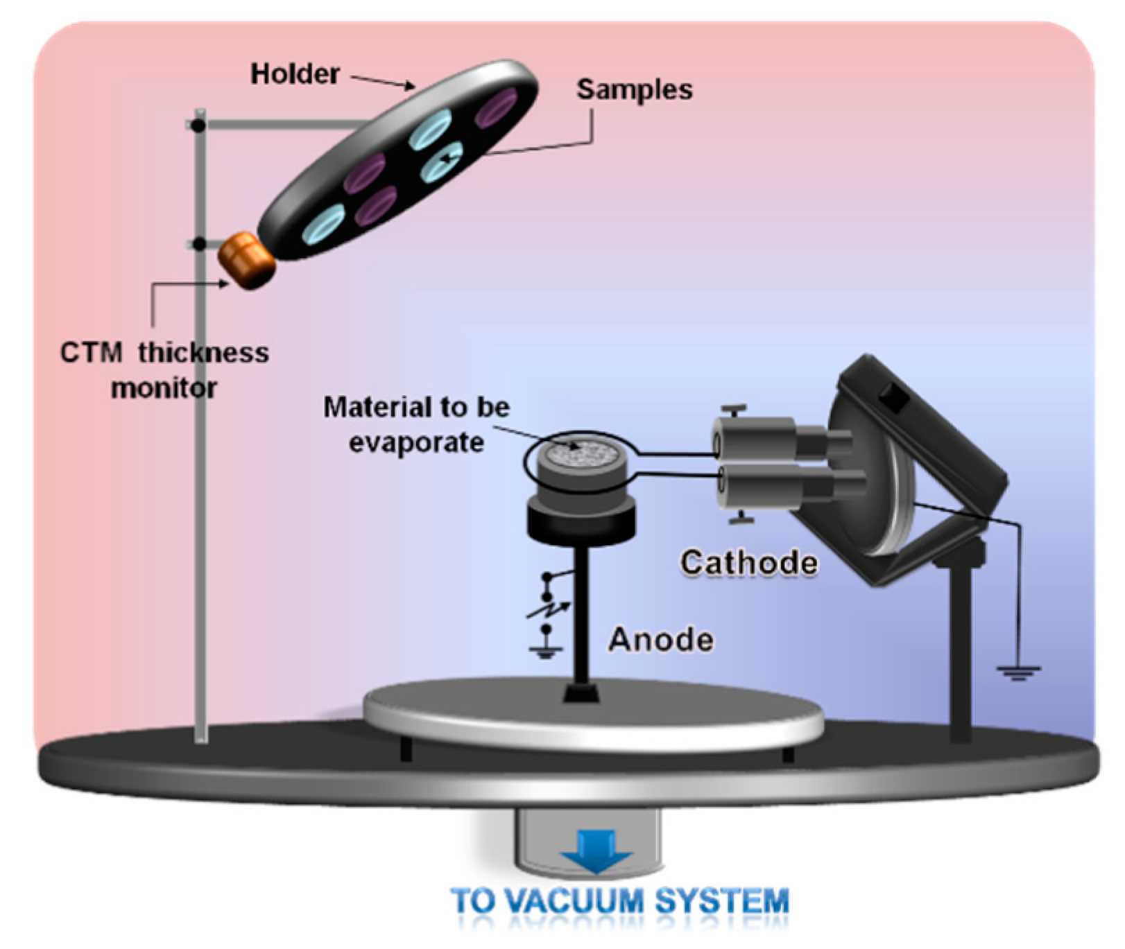
In the TVA method, the energy introduced into the system for ignition of the plasma is supplied by a low-voltage source powering the hot cathode and a high voltage source that ignites and supports the TVA discharge. The thermionically emitted electrons from the heated cathode filament electron are accelerated by the applied high voltage between the cathode and anode. The electrons bombard the material to be deposited, e.g., carbon. The increasing temperature of the anode material increases its vapor pressure. At sufficient vapor pressure, the vacuum arc is ignited between the hot cathode and anode. A substantial part, around 10%, of the evaporated neutral atoms becomes ionized. Consequently, the thin film on a substrate grows due to the bombardment of both the neutral atoms as well as ions of the depositing material. This is a major advantage in obtaining high-purity thin films, because the discharge burns in high vacuum and the film is bombarded during its growing with its own atoms, which are ionized. The ions have a random thermal energy superposed on a much higher directed energy towards the wall. Directed energy of ions is controllable and can achieve values up to 500 V. The thickness of the deposited film can be controlled during deposition by a monitor and can be variable, from tens of nm to microns, depending on the desired application.

2.1. One electron Gun and One Crucible

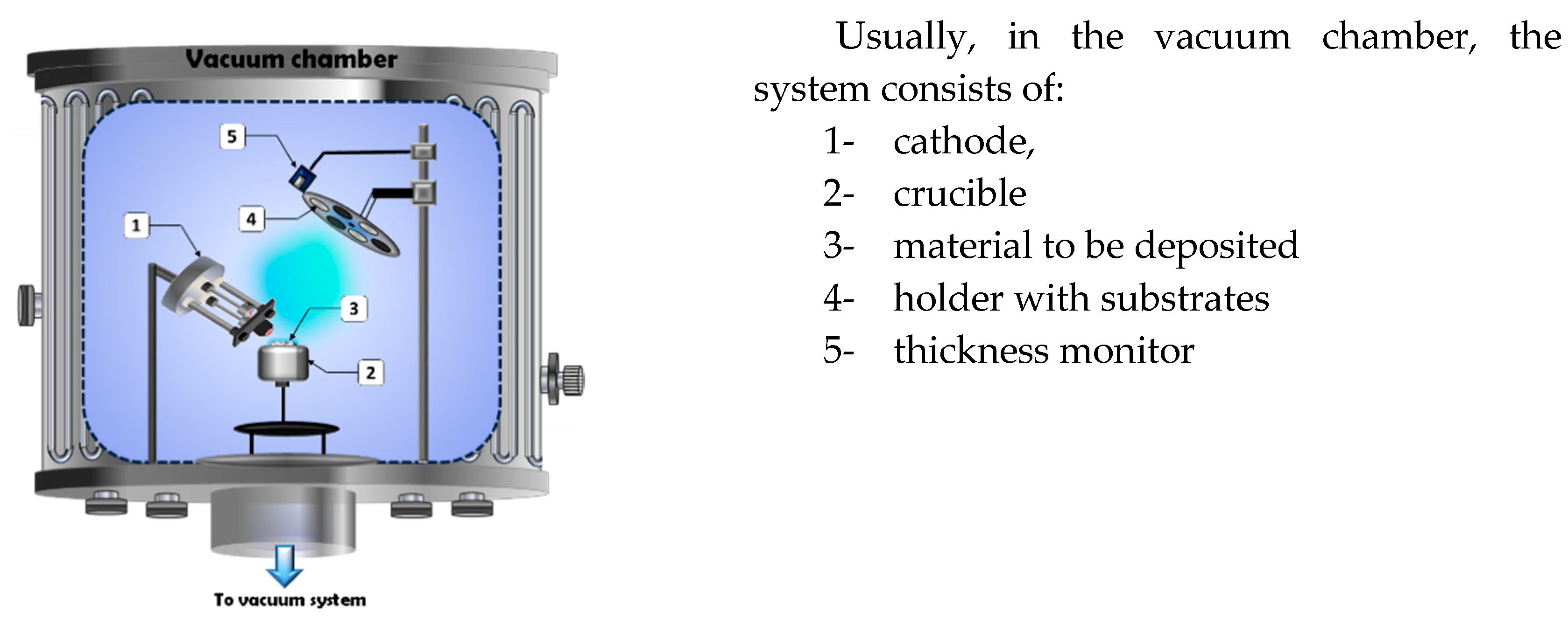
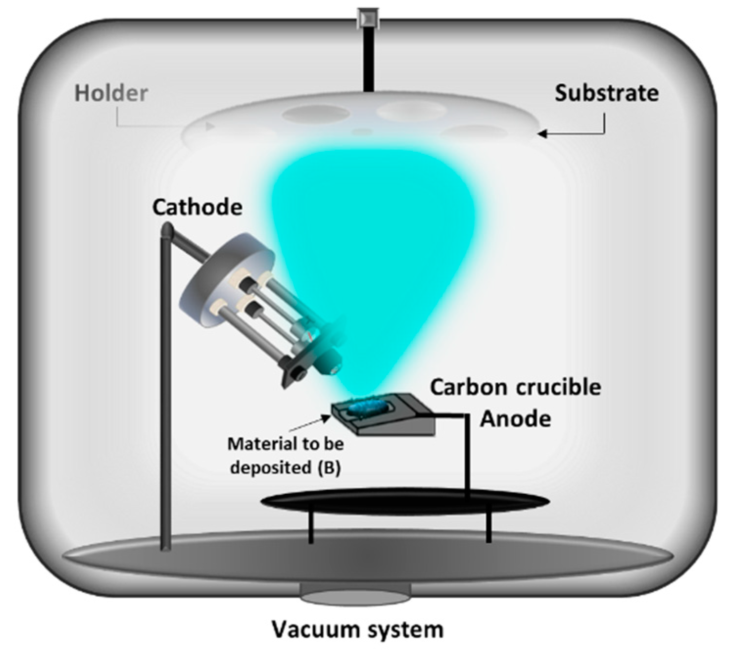
The mostly used arrangement of the TVA apparatus, found in more than 170 our references, is the simplest combination of one electron gun and one crucible with material. As an example this arrangement is illustrated in the ref. [34], see Figure 5.
This simplest arrangement, one electron gun and one crucible, is applicable also in cases when the intention is to deposit a film from several materials, which can be put together into one crucible; see e.g., ref. [36,37,38,39,40].
As an example we can discuss in more detail the paper in ref. [41]. They studied the silicon doped gallium nitride thin films deposited on glass and polyethylene terephthalate (PET) substrates. For that, they put into the tungsten crucible both Si (0.06g) and GaN (0.03g) materials together. The authors concluded that the thermionic vacuum arc method presented important advantages for optical and industrial applications of these layers.
Another experiment, with a different shape of crucible experiment was configured for the deposition of boron. The experimental set-up is presented in Figure 6 [42]. Boron has a melting temperature 2076 °C and the boiling temperature 3927 °C, very comparable values with those of refractory metals. Voltages up to 4 kV were used to ignite and to maintain the boron TVA discharge; the arc current and the cathode filament current are not quoted in the paper. As the substrates, the glass plates, stainless steel, copper, KCl crystal, and Mg deposited glass plates were used. The substrates were positioned at the vertical distance 100 mm from the anode crucible; the achieved deposition rate was up to 200 nm/min. The interatomic distances measured on the boron film by an electron diffraction revealed a nanostructured boron film with a d-spacing corresponding to a rhombohedral structure space group R-3m with a = 1.092 nm and c = 2.381 nm.
As a disadvantage, the authors quote the reduced lifetime of the tungsten filament due to the boron vapor interaction with the tungsten cathode. That is a general disadvantage of a directly heated cathode that can react with certain materials to be deposited. This disadvantage can be possibly reduced by using an indirectly heated cathode. However, the authors did not find traces of tungsten in boron films [43].

2.2. One Electron Gun and Two/Three Crucibles

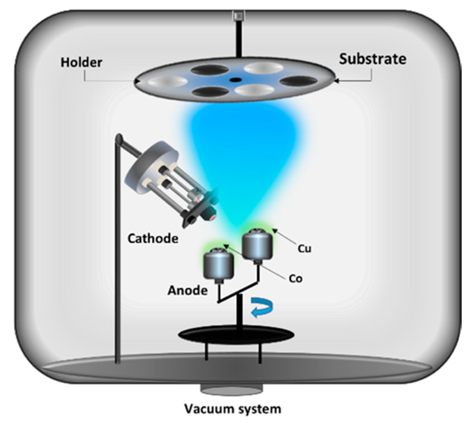
Since the electron gun produces a comparatively well-focused beam it is impossible to direct one beam to two crucibles. However, when two crucibles are fixed on a turntable, like in Figure 7, it is possible to deposit multilayers without breaking the vacuum in the TVA system. The arrangement is suitable for deposition of the nanostructured materials with special resistive magnetic properties [44,45,46]. For that purpose, the Cu and Co thin films were grown by the TVA method in this arrangement. Successive layers of Cu and Co were deposited on ceramic substrates using tungsten crucibles each containing Cu and Co metals, respectively. The combination of two magnetic (Co) layers separated by a non-magnetic (Cu) layer gives the possibility to create material with magnetoresistive properties, i.e., to change the resistance of such material by an external magnetic field.
If the spins in the magnetic layers are oriented parallel, the resistance is low; if they are anti-parallel, the resistance is high. The authors achieved the relative magnetoresistance (change of resistance due to the magnetic field measured by the resistance without the magnetic field in percent) of their samples to reach 22%.
A similar arrangement, but with three crucibles was used in [47]. Here the fusion-related mixed layers containing tungsten, nickel, and iron in fixed and rotated deposition geometries were deposited by one electron gun and three crucibles on a turntable.

2.3. Two Electron Guns and Two Crucibles

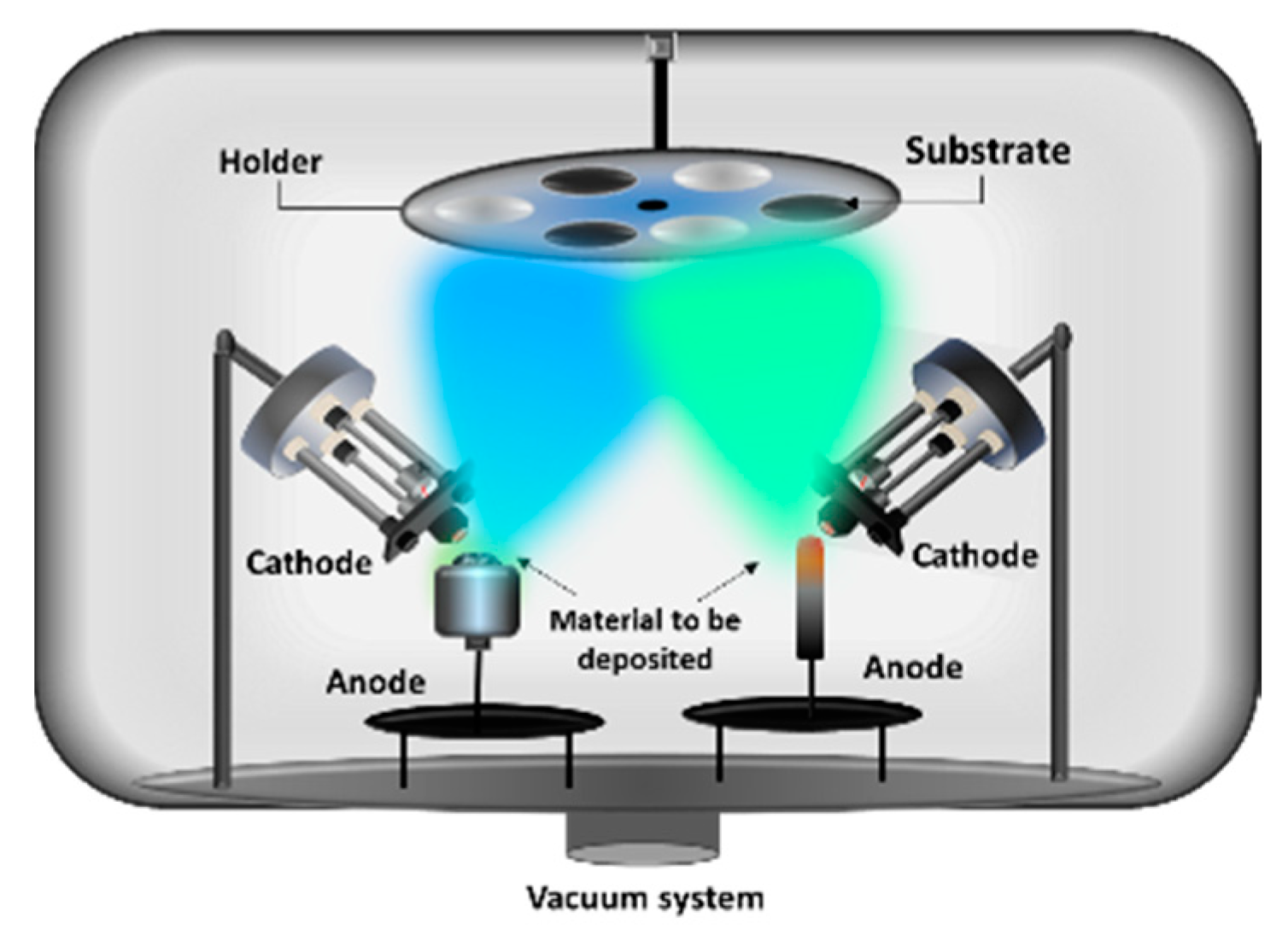
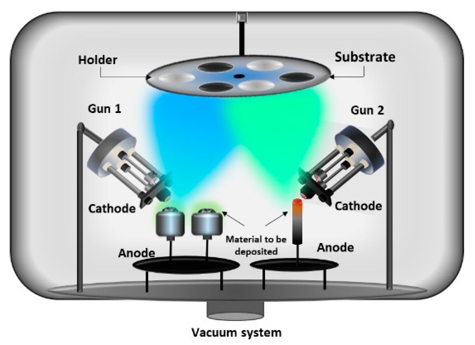
Materials composed of alternating thin layers of two different material offer extraordinary strength, hardness, and heat-resistance and new useful properties. The giant magnetoresistance (GMR) layers described above may serve as an example. The simultaneous deposition of two different materials without the need of movable material support enabled the TVA arrangement with two guns and two crucibles. Out of approximately 20 references using such TVA arrangement, we chose as an example the work by [48]. Here a method was developed to grow metal-carbon zero-stress films for micro-electro-mechanical-systems (MEMS) applications. The TVA arrangement is shown in Figure 8. For minimizing the internal stress in the carbon layer, a metal (Fe, Cr, Al, Ni) interlayer was deposited simultaneously with carbon using the second electron gun. The coatings were performed on mirror-polished Si and glass substrates.
An average roughness of the carbon films was 2–3 nm and the diameter of the embedded metal particles 3–11 nm. The electric resistance of the films decreased with increasing atomic number of the metal additive. In the work [49] a carbon rod was used as a source of carbon instead of a crucible.

2.4. Two Electron Guns and One Crucible

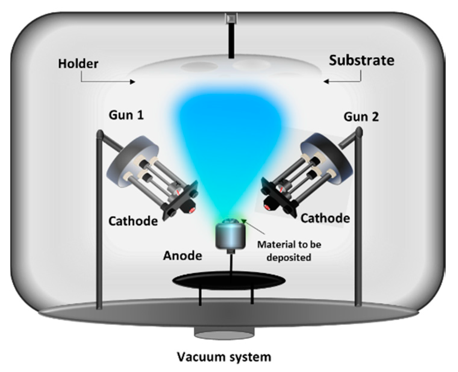
In order to obtain very smooth and uniform thickness along the substrate, another configuration has been used, such as two electron guns and one crucible. In this case, two electron guns, symmetrically arranged with respect to the central line, are incident on the materials contained in the crucible; see Figure 9.
This configuration is suitable especially for deposition of the dielectrics and semiconductors, where the transfer of the heat is not so fast like in the case of other metals [50].

2.5. Two Electron Guns and Three Crucibles

A variation of the two above mentioned arrangement was used e.g., in [51]. The intention of the authors were the materials showing the giant magnetoresistance (GMR) and the Magneto-Optical Kerr Effect (MOKE). They created a multilayer/sandwich structures where the layers of magnetic material (Ni, Co) were interleaved by Cu layers.
One electron gun was used together with a graphite crucible containing copper. For the magnetic materials, the authors used another electron gun that aimed at a circular rotary graphite disk. On this disk were placed two graphite crucibles, each containing Ni and Co respectively, as depicted in Figure 10. The maximum relative magnetoresistance reached for the 8-layer Cu-Ni-Cu-Co-Cu-Ni-Cu-Co structure was 19%. MOKE measurements confirmed the GMR effect.

2.6. Three Electron Guns and Three Crucibles

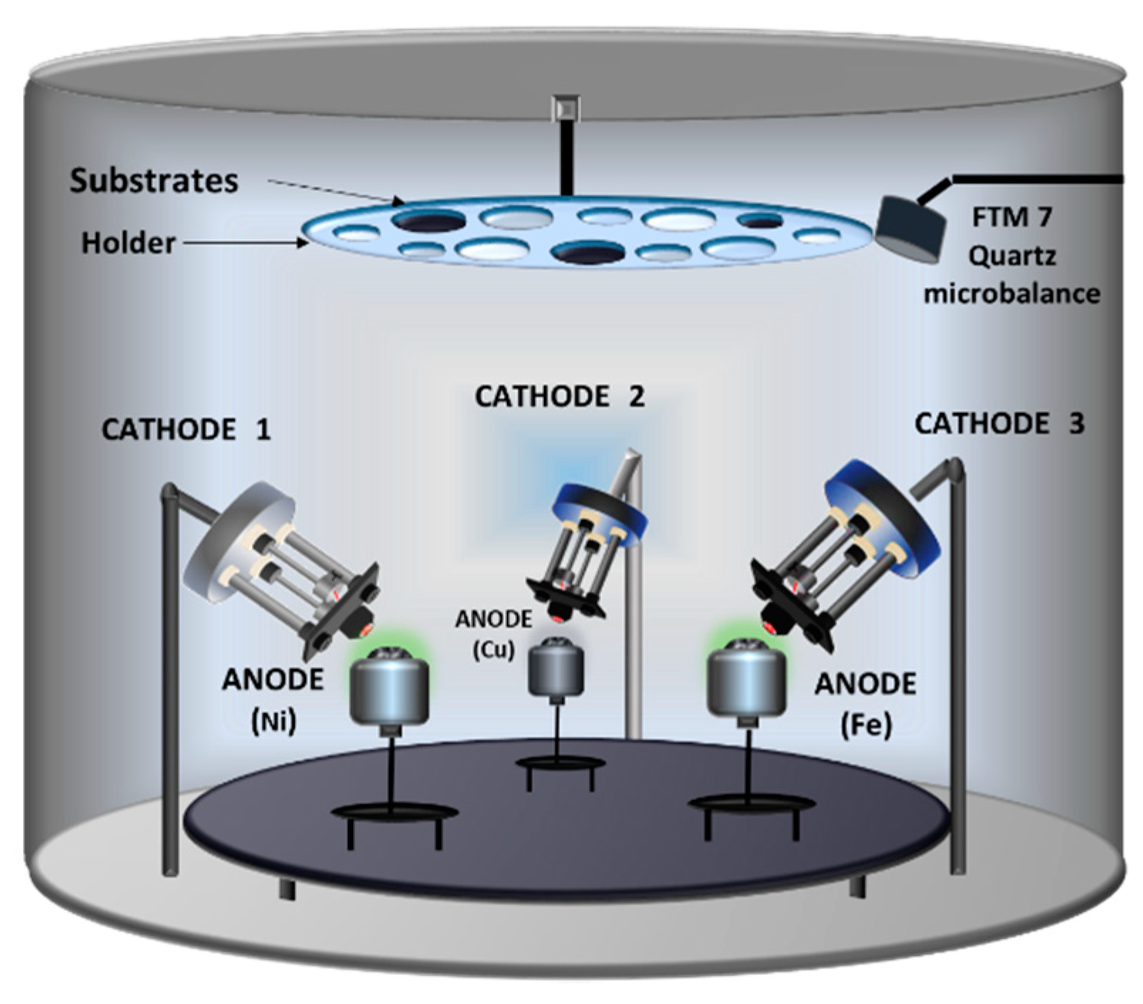
The effort for creating layers of several materials led to further refinement of the TVA system. In ref. [52] the authors intended to deposit granular ferromagnetic films. Such a material usually consists of nanometric magnetic grains (Fe, Co) uniformly distributed within a nonmagnetic matrice (copper, silver, or gold). The sequential deposition applied e.g., in the mentioned work in [46] was unusable; it was necessary to deposit three materials, Fe, Ni, and Cu simultaneously. That was achieved by constructing a TVA system with three electron guns aiming at three separated crucibles that contained Fe, Ni, and Cu, respectively. The schematic diagram of the system is given in Figure 11. All three electron guns operated simultaneously resulting in a layer consisting of all three materials deposited on a silicon substrate. The authors investigated on their samples successfully the Magneto-Optic Kerr Effect (MOKE) and the effect of magnetoresistance.

2.7. Three Electron Guns and Nine Crucibles

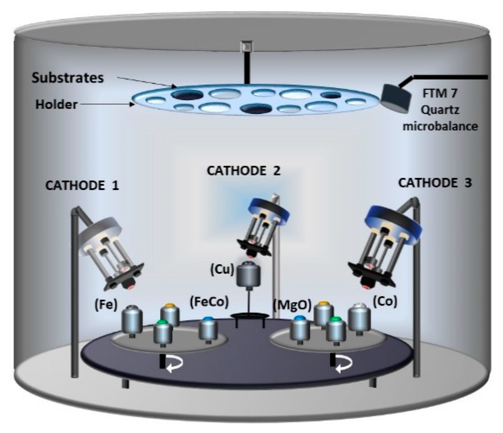
The effect of giant magnetoresistance (GMR) and that of tunneling magnetoresistance (TMR) and their combinations was investigated in [53]. For studying GMR the authors prepared the layers in which the magnetic material Fe–Co was embedded in a Cu matrix. The layers that were made to model the combinatorial GMR + TMR effect were made as a combination between Fe–Co alloy, embedded in a matrix of Cu combined with MgO. While the Fe and Co have similar melting points (1538 °C and 1495 °C, respectively), the other materials have very different melting points (Cu 1085 °C, MgO 2852 °C).
It was necessary to use three electron guns for evaporating Fe, Co, MgO, and Cu, see Figure 12. For the GMR layers the Fe and Co materials were deposited separately, for the TMR layers the authors used a Fe-Co alloy placed in one of the crucibles. Due to different positioning of each sample with respect to the anode-cathode, different elemental concentrations were obtained in a single batch of samples. The relative magnetoresistance varied with the relative elemental concentration between 1.31% and 26.4% for the Fe + Cu + Co thin films; for the FeCo + Cu + MgO structure between 4.5% and 19% at the sample temperature 27 °C. For both layers the magnetoresistive effect depended on temperature: for the former it was highest at 40 °C (80%) and for the latter at 43 °C (69%). The results confirmed the efficiency of TVA method in obtaining combinatorial magnetic structures.

2.8. One Ring-Shaped Electron Gun and One Crucible

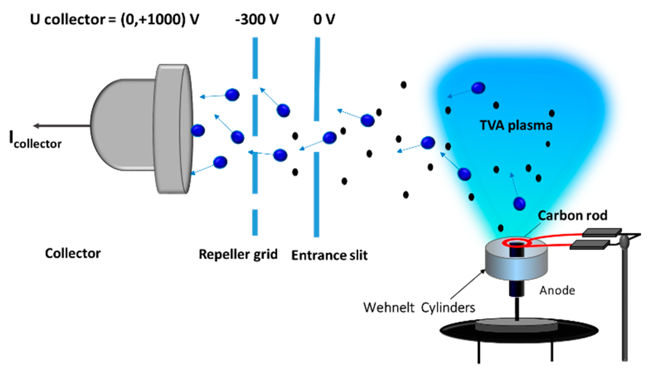
A sophisticated construction of a TVA system is presented in ref. [54]. In this work, the original arrangement of the electron gun was modified in a way that it surrounded the anode material, see Figure 13. The ring-shaped tungsten filament, the electron beam focusing Wehnelt cylinder and the anode material (this time the carbon rod) are arranged along the same axis of symmetry. The TVA plasma is localized above the anode, where the highest vapor pressure is obtained. The ions are accelerated to the grounded chamber walls and to the substrate due the potential difference between the plasma potential and the ground; that is a similar mechanism as in the original TVA design [32]. The authors claim that the new setup offers higher plasma stability than the original design. The authors investigated the influence of plasma parameters on the preferential formation of sp3 phase in carbon films; the phase that is responsible high mechanical properties in diamond-like carbon (DLC) films. The authors concluded that the ration of the sp3:sp2 phases is higher at higher applied voltage; a consequence of the higher energy of carbon ions. In addition, since no buffer gas or catalyst was needed to support the DLC film deposition process, the films were obtained hydrogen-free and pure.

2.9. Two Ring-Shaped Electron Guns and Two Crucibles

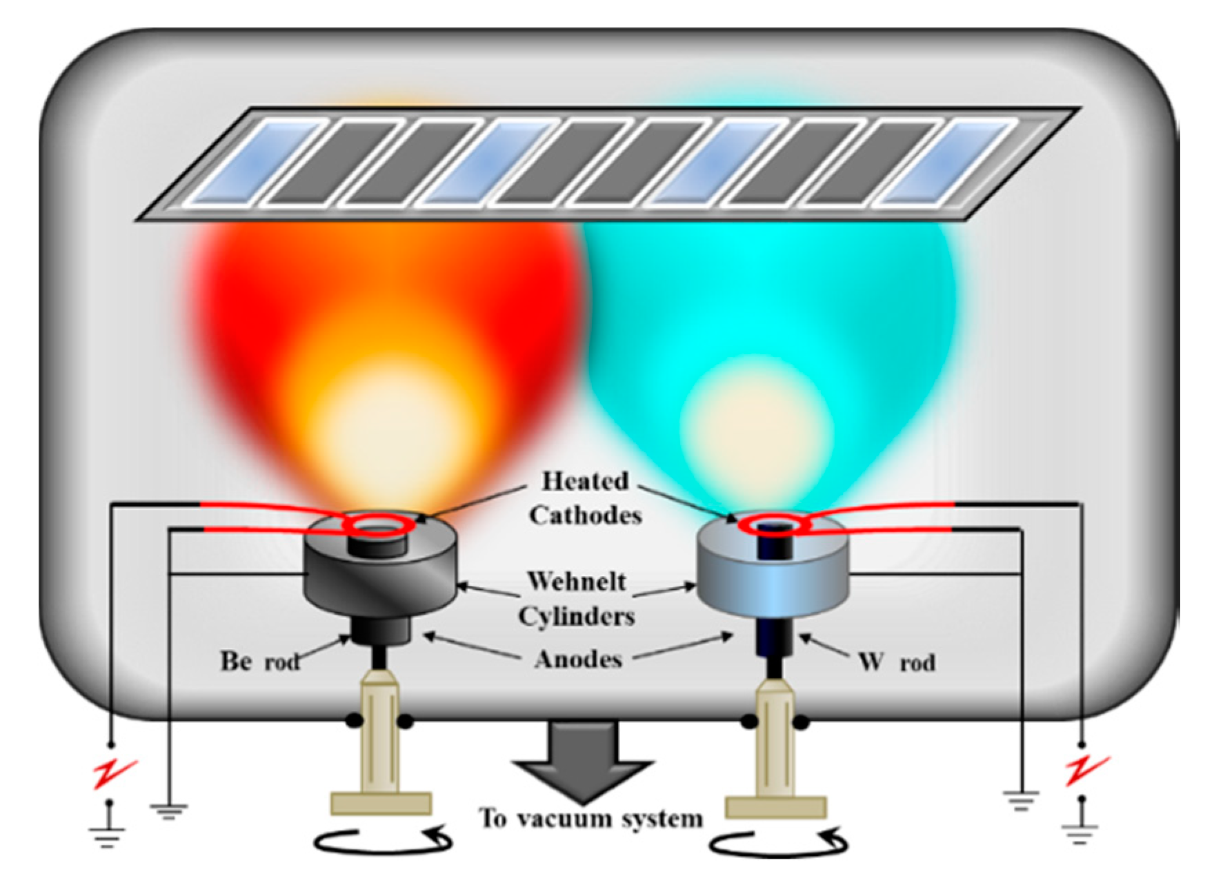
One of the most important application of the TVA system consists in creating the Be and W layers intended for the ITER first wall. The melting point of tungsten lies at 3422 °C, that of Be at 1287 °C. Especially interesting for fusion application are the mixed Be-W materials that are likely to be created due to material migration on the tokamak walls. These mixed surfaces can influence fuel retention and desorption from the initial plasma-facing components, which in turn will affect the hydrogen recycling and in-vessel tritium inventory. For this reason, the work from ref. [55] studies the deuterium retention in the mixed Be-W films in laboratory. That is not an easy task in spite of the Be toxicity; the experimental work with Be requires hence approvals by the respective official bodies. Since the melting points of both materials are vastly different, the authors used the separate crucibles heated by two ring-shaped electron guns, see Figure 14. In this way, the precise control of the Be-W ratio in the samples was allowed. The work yielded important information on the samples morphology and the preferential sputtering effect of Be at the surface following the plasma exposure. The research was performed in collaboration with Center for Energy Research, University of California, San Diego, USA.

2.10. Gaseous Thermionic Vacuum Arc (G-TVA)

Previously reported was TiC grown by the reaction of Ti metal vapor, created by the interaction of an electron beam with a Ti target, and C2H2 gas atoms [20]. The gaseous thermionic vacuum arc (G-TVA) system was first presented by authors in ref. [56] as “an extension of TVA input materials from solid samples to gases and liquids for carbon thin film deposition”. By adding acetylene into the volume between the electrodes, the G-TVA system uses a sintered filter that serves as the discharge anode [20]. Through the filter, the gases or vapors enter the discharge chamber; that resembles anode evaporation under the bombardment by an electron gun. The added gas creates a gradient of pressure nearby the anode; consequently, the G-TVA discharge is concentrated there. That is a similar feature as in a TVA system, but here the gradient of pressure arises due to the vapors from the melted anode material.
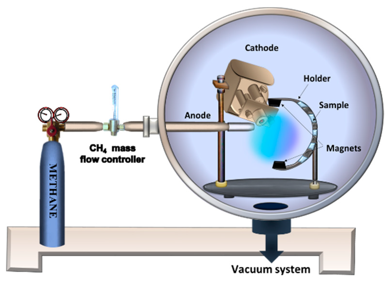
Figure 15 shows a simplified diagram of the G-TVA system. As in a standard TVA, the system consists of an electron gun aiming at the anode, and the sample holder. An isolated tubing feeds the gas/vapor precursor into a disk of sintered metal powder placed in the anode. The sintered metal powder disperses the incoming gas. In this way, the G-TVA discharge creates a plasma that is uniformly distributed over the full anode surface. The fact that plasma is localized just above the gas inlet infers that the heat transfer from the hot core plasma on the substrate is minimized. That represents one of the main advantages of the G-TVA system: the possibility of coating the thermal sensitive materials as polymers or dielectrics. Further, the ignition of the discharge is easier in G-TVA than in TVA since the gas state is already achieved. Finally, the deposition rate in G-TVA is rather high, up to 100 nm, and the created films are, as a rule, smooth, uniform, and pinhole-free.
The G-TVA discharge ignites when the DC voltage is applied at the anode (the cathode is grounded) and the thermionic cathode is in operation. The distance between the electrodes is critical; too small a distance results in a cold cathode discharge. The first experiments reported in [56] were performed in methane with distance between the electrodes of 5 mm. The anode-sample distance varied from 55 mm up to 75 mm. Percentage of sp2 and sp3 bonding was investigated by XPS in the deposited carbon films.
First plasma diagnostic of the G-TVA discharge in methane was realized in [57]. The optical emission spectrum showed the dissociation of CH4 into hydrogen and the CH radicals.
It is obvious that a TVA system can be rather simply converted into a G-TVA system, and vice versa. A system like that was constructed in [58]. The mechanical properties of the DLC films deposited on silicon and glass substrates by the both systems were investigated by using the nanoindentation techniques. It was concluded, that the both methods could produce DLC films with a comparable hardness. In [59] and [60], the hydrogenated amorphous carbon layers (a-C:H) were deposited by G-TVA on silicon and glass substrates. The surface free energy and the mechanical properties of the films were investigated. The comprehensive comparison of both the TVA and G-TVA methods from the point of view of producing DLC coatings is given in [61]. A system that combines a ring shaped cathode and the anode that allows to inlet precursor gas into the discharge chamber has been also developed and called the C-TVA (compact-TVA) [62,63].

3. Diagnostic of TVA Plasma

From the very beginning of TVA system invention, the researchers aimed at understanding the physical processes going on in the TVA plasma. The plasma diagnostic methods included basic macroscopic measurements, optical emission spectroscopy, Langmuir/emissive probe studies, mass-spectrometry, and ion-energy analysis. The following survey is organized in groups in accord with the respective diagnostic method.

3.1. Basic Macroscopic Measurements

In almost all of these references one finds certain basic macroscopic measurements of TVA discharge. They include e.g., the I-V characteristics of arc discharge, voltage applied between the TVA electrodes, filament current of the thermionic cathode, distance between the electrodes, the anode-substrate, etc. The I–V characteristic of the anodic arc with stainless steel anode (workpiece to be welded) was measured [27]. In the non-ignited state, the I-V dependence was similar to that of a vacuum diode; high voltage between hot thermionic cathode and grounded anode induced only a small current. After the arc was ignited, the voltage dropped and the current increased; however, the arc I-V characteristic still featured the positive dynamic resistance. Spectral investigations proved that only metallic lines were present. This fact proved that the discharge occurs in the vapors of the metal continuously evaporated from the melted spot on the anode surface.
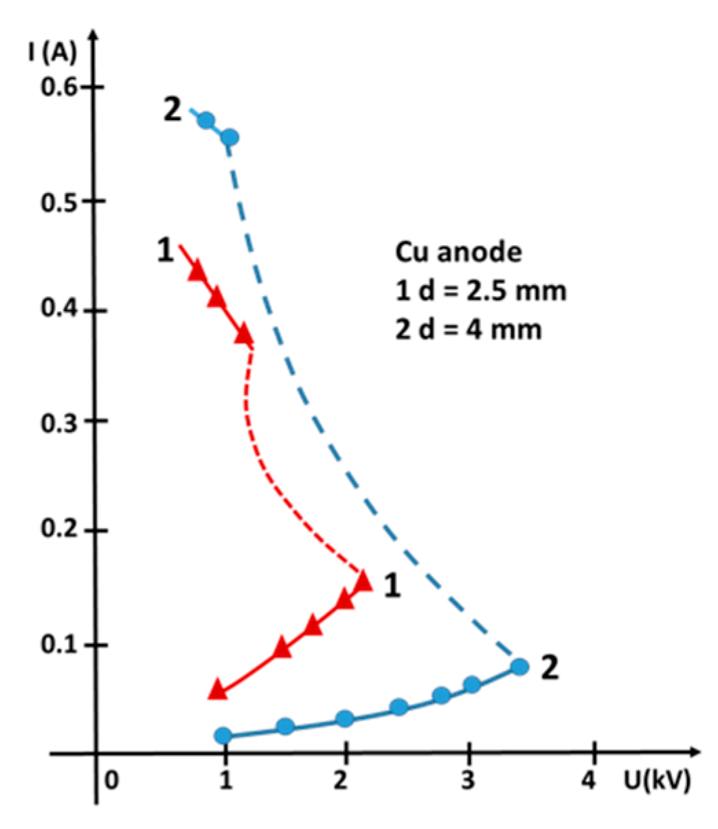
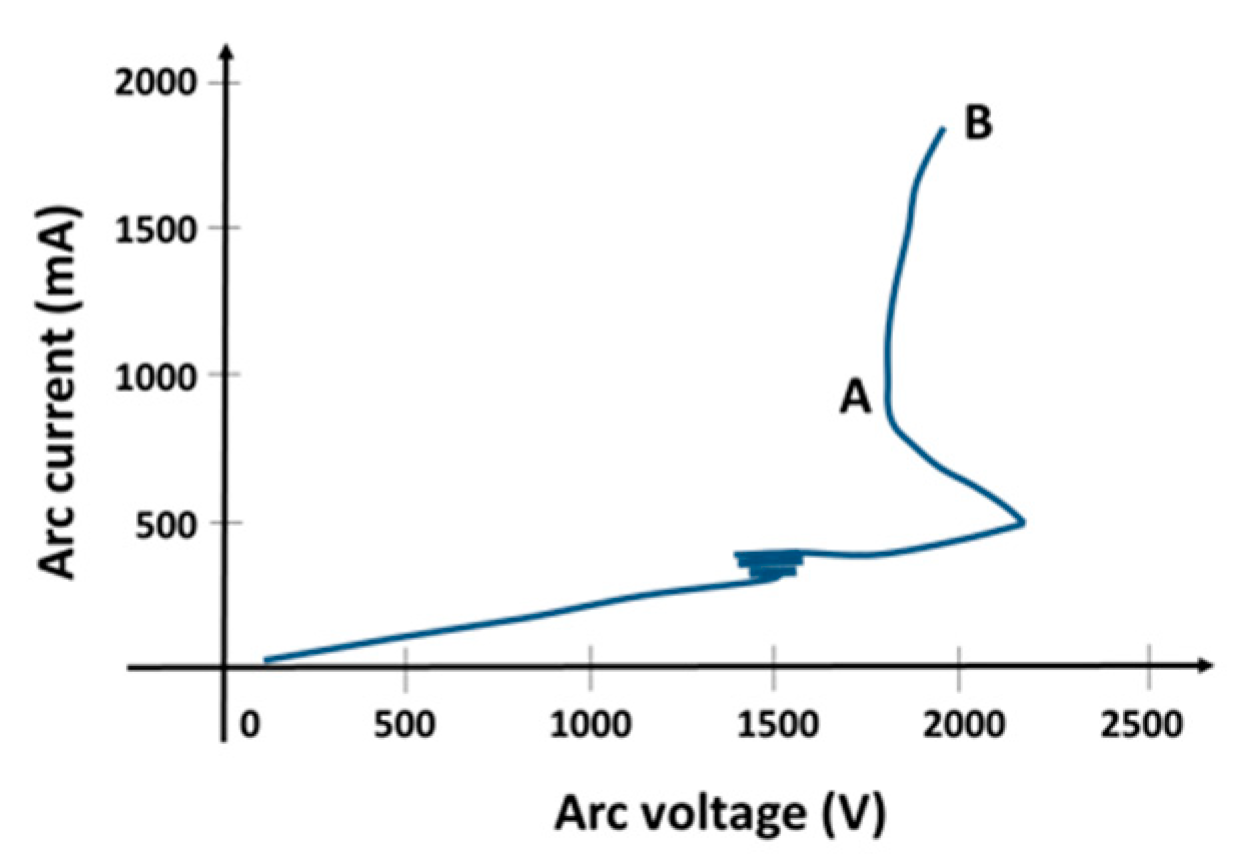
In [28] similar measurements were performed with a Ti and Cu anode. This time a special vacuum apparatus, later called TVA, was constructed. The I-V characteristics were measured for both materials and for different anode-cathode distances. Sample of measurement with Cu anode shows Figure 16. The curves corresponding to rather high voltage and low current represent the “vacuum diode” characteristics; no discharge is present. A dotted line illustrates the instant of the arc ignition. We recognize the typical arc I-V characteristic featuring the negative dynamic resistance. The arc ignition voltage increases, as one would expect, with increasing the discharge gap. Similar measurements of the I-V characteristics in the vapors of various metals (Zn, Pb, Ag, Sn, Cu, Au, Co, Ti) and Cu-Ag and Cu-Sn alloys. Cu-Ag and Cu-Sn alloys in various mass ratios were performed in [64,65]. The ignition and the operation of the gaseous TVA with CH4 as precursor diffusing through the sintered powder anode were tested in [56]. Another measurement of the I-V characteristic of a TVA discharge in Cu vapors is presented in [66]. This work shows also the dependences of the plasma potential on the arc current and concludes that the energy of ions impinging the substrate is given by the potential difference between the plasma potential and the substrate potential, which is usually grounded. The research done in [54] shows that the TVA discharge provided by a ring-shaped cathode may also have a positive differential resistance within a certain current range, see Figure 17. Consequently, for particular film requirements the I-V range can be tailored to obtain either high ion energies (A) or high ion densities (B). The I-V characteristics of a TVA discharge in Cu vapors for different electrode distances and different cathode heating currents can be found also in [67,68,69]. In ref. [70] the I–V characteristics have been measured in Ag and alumina vapors.

3.2. Langmuir/Emissive/Heated Probe Measurements

The paper by [22] does not investigate the TVA, but an anodic arc created with cold cathode (arc is created by shortly contacting the electrodes). However, this work presents the first Langmuir probe measurements of the anodic arc plasma parameters; the anode materials were Al, Ti, and Cr. The measured electron temperatures were around 0.5 eV and slightly depended on the arc current. The electron densities were within the order 1017 m−3 and increased with increasing the arc current for all the three anode materials. In addition, the total energy of the ion reaching the substrate was estimated around 5−6 eV based on a simple model of the expanding plasma. Finally, in the summarizing paper, where the arc was operated in the range of currents 20-200A, [24] quotes the electron temperature 0.4−1 eV, the electron density 1015–1018 m−3, the ion temperature about 1eV, and the degree of ionization 0.5–25%.
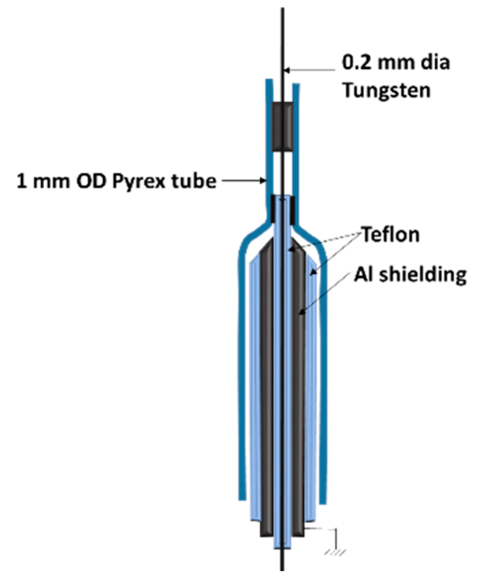
Diagnostic studies of the TVA plasma have been presented in [32]. Apart from refined measurements of the arc I-V characteristics, also the results of the Langmuir probe measurements of the expanding plasma are illustrated. An example of a proper construction of a Langmuir probe for plasmas used for deposition of conducting layers illustrates Figure 18. Within the arc current range 2.4–3.6 A with a Cu anode the electron densities were between (2.7−6.3) × 1015 m−3, the electron temperatures 6–15 eV, and the degree of ionization 0.6–6%. The ion energy analyzer indicated the ion energies above 100 eV. The more accurate ion energy measurements are presented in [33] together with the measurements of the potential distribution in the direction of plasma expansion done with a movable Langmuir probe. The authors concluded that the ions are accelerated in the volume that is a unique feature of a TVA system. Consequently, the ion energy—the parameter influencing substantially the deposited film parameters—can be adjusted easily by proper choice of operating parameters and the substrate-arc distance. Similar measurement can be found in [71].
The measurements by a Langmuir probe in a TVA plasma are difficult, since the deposition rate is, as a rule, high, and the non-conducting layers on the probe and/or on its ceramic support, degrade the probe characteristic.
An emissive probe was applied for measurements of the plasma potential distribution along the TVA discharge axis [68]. The hot tungsten loop of an emissive probe eliminated the formation of disturbing layers on the probe surface and the floating potential of a sufficiently emitting probe estimated the plasma potential. The topical review on emissive probes can be found in [73]. The emissive probe was further applied in [68,69].
It has to be noted, that one has to be careful when using an emissive probe for plasma potential estimation. The emitted electrons create a potential well near the emitting wire that causes an error of plasma potential estimation; see e.g., [74]. The situation is even more complicated by the fact that the difference between the “true” plasma potential and the floating potential of an emissive probe is influenced by the plasma potential fluctuations, see e.g., [75,76]. On the other hand, even when burdened by some inaccuracy, the emissive probe yields important data for optimization of a particular TVA deposition process, e.g., [77].
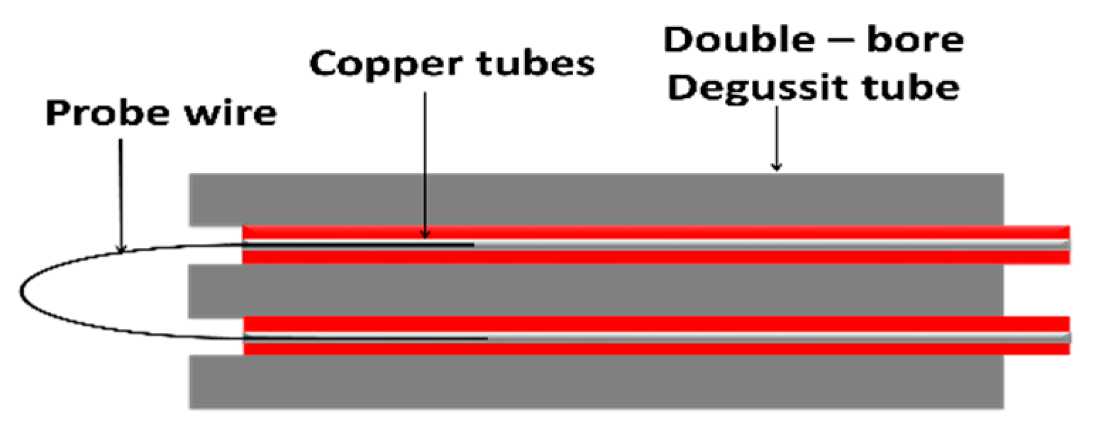
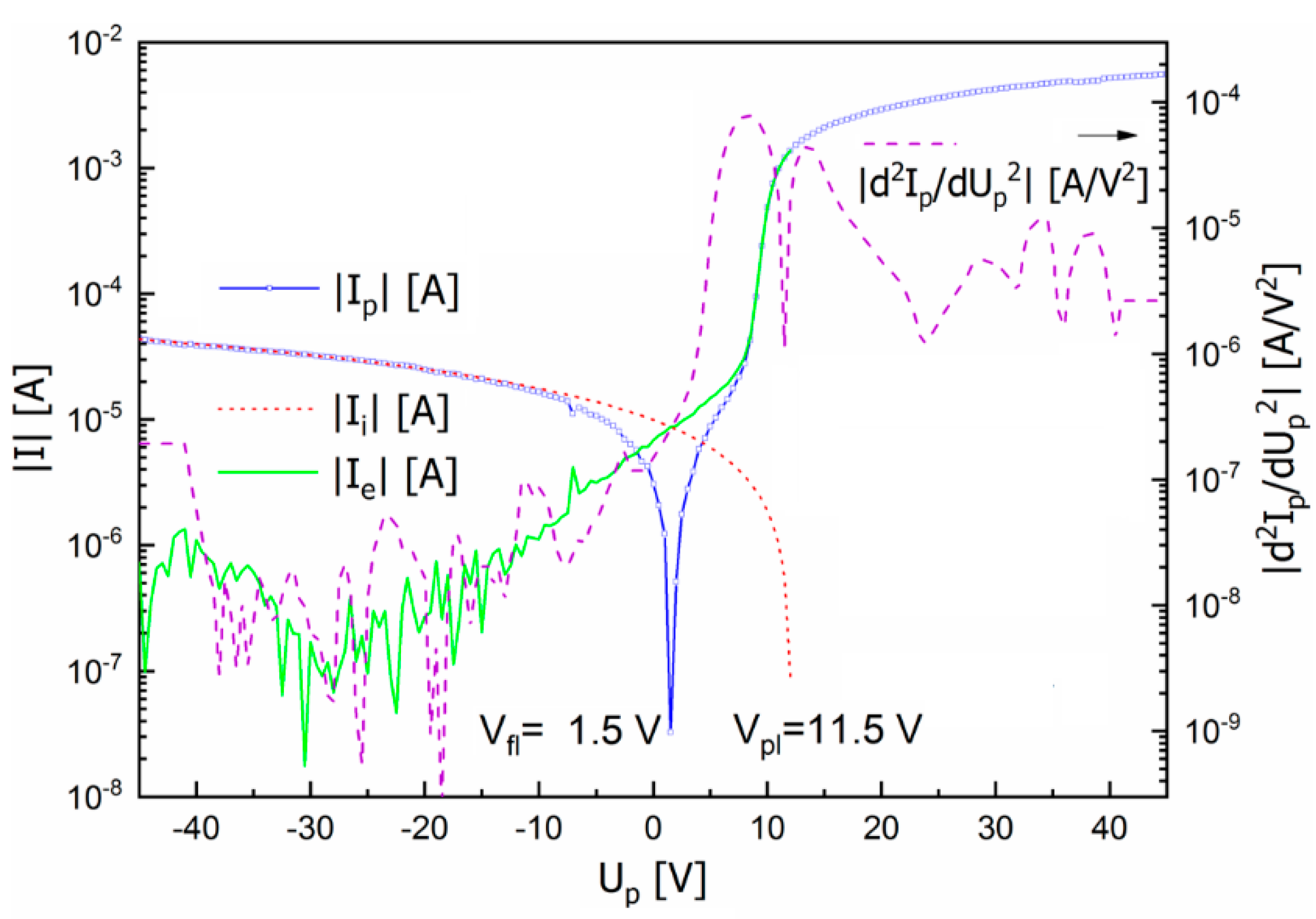
While the emissive probe serves as a sensor of the plasma potential, it cannot be used for the electron temperature or the electron density estimation. That can be performed by a so-called heated probe. The heated probe is of a similar construction as an emissive probe, i.e., in a form of a tungsten wire loop, but heated to a lower temperature when it does not emit electrons; see Figure 19. The high temperature reduces creation of a non-conducting layer on the probe surface that would degrade the probe characteristic measurement otherwise. The probe temperature must be higher than the boiling point of a material to be deposited in the TVA system. Measurements of plasma parameters in the TVA discharge in Mg and in Mg–Zn vapors by a heated probe have been performed in [78] and [79], respectively. In the latter, also the electron energy distribution function (EEDF) was determined from the second derivative of the heated probe characteristic with respect to the probe voltage, see Figure 20.

3.3. Optical Emission Spectroscopy

Very fine optical emission spectroscopy (OES) measurements of the electron temperature in TVA plasma with Ti anode one finds in [80]. The Ti film deposition on the optical window of the vacuum system was eliminated using two mirrors. The planar grating spectrograph controlled by a computer was used to record the emission spectrum. Finally, the Boltzmann graph method was used to calculate the excitation temperature of Ti atoms. Under the assumption of a local thermodynamic equilibrium (LTE) the excitation temperature of the Ti atoms is approximately equal to the electron temperature. In the LTE state, the relative intensities of the spectral lines emitted by the atoms of the same kind depend only on the plasma electron temperature. The estimated temperature around 2800 K corresponded to the surface temperature of the melted titanium obtained by absolute intensity measurements of the anode surface radiation at a wavelength λ = 607.5 nm [22].
Similar OES measurements in the TVA discharge in silver vapor yield in [81] and in [70]. The Ag I 328.068 nm and Ag I 338.289 nm lines have been selected for evaluation of the electron temperature Te using the Boltzmann relation. The electron temperature of the silver plasma was estimated to be in the range 2000-2700 K. That corresponds well to the Ag melting and boiling point 962 °C and 2212 °C, respectively. Ref. [70] recorded also an optical emission spectrum of the TVA discharge in alumina vapors. That spectrum resembled black body radiation; continuous curve with peaks corresponding to the spectrum of neutral Al. This finding the authors attributed to high temperature of the tungsten crucible.
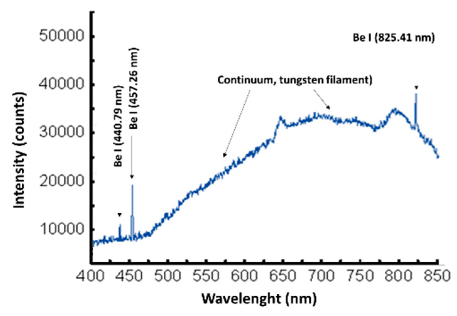
In Figure 21 there is depicted an optical emission spectrum of Be TVA plasma recorded in [82]. This time the continuum part of the spectrum is due to the radiation of the tungsten filament of the electron gun that was impossible to shield. For calculation of the temperature using the Boltzmann relation the intensities of the Be I lines have been estimated by subtracting the continuum background from the total measured intensity. Electron temperature was found in the range of 6620–7900 K; it increased with increasing the anode-cathode potential and decreased with increasing the discharge current.
The nickel TVA plasma has been studied by OES in [83]. By a calibrated system the authors performed an absolute measurement of the emissivity of the Ni pool on the top of the anode and by using the Stefan-Boltzmann relation estimated the anode temperature. The temperature of the Ni pool was found within 1500−2500 K (melting point of Ni is 1728 K). They could observe the pool temperature both before ignition and during arc running; it depended on the total discharge power and on the filament current of the electron gun cathode. Knowing the Ni pool temperature, they could calculate the local pressure of the Ni vapors and the evaporation rate. The electron temperature Te in the range of 2 eV they estimated from the ratio of the intensities of two pairs of Ni spectral lines: (i) Ni I 380.714 and Ni I 385.830 nm, and (ii) Ni I 380.714 and Ni I 397.356 nm. It was found that plasma parameters increase with increasing the discharge power, however, after the arc ignition have relatively constant values. The opportunity to have in real time the vapor pressure, the evaporation, and the deposition rate at hand enabled an optimization of all process parameters.
A very interesting application of OES in the XUV range was presented in [84]. In this work the tungsten carbon bi-layer having prospective application in the ITER first wall or divertor were deposited by TVA. Since the key interest in these layers resided in their resistance against the energetic radiation the films were irradiated by a train of pulses by the TEWALAS laser system. The high surface energy density (around 0.5 TJ/m2) of the laser pulse created a plasma plume in front of the prepared C-W structure. Such a plasma contains many charged ions that mostly radiate in the XUV spectral range 10-22 nm. By considering the band amplitude variation in the center of the observed spectral range, the authors concluded the sequence of individual layer ablation: first the carbon layer, then the tungsten layer followed by a graphite substrate.
By presenting several examples of the OES application for estimating the TVA plasma parameters, we intended to illustrate the important features of this diagnostic. OES enables the estimation of the excitation temperature of the atoms of the used material, and, consequently, under the assumption of LTE, also the electron temperature. The electron temperature in TVA arc plasma is usually low, around or below 1 eV. Furthermore, with a calibrated system the absolute emissivity measurements give the surface temperature of the molten material at the anode that in turn enables the estimation of the local pressure of the respective vapors and the evaporation rate.

3.4. Mass-Spectrometry, Ion Energy Analysis

The interest in the DLC films provoked experiments in depositing DLC-type films by the TVA technique. The structure, the texture as well as physical properties of DLC films depend on the growth conditions, which determine the relative concentration of the sp3 and sp2 bonds. Growth conditions include a series of plasma parameters among which ion energy distribution and ion mass are the most important. To our knowledge, the first spectral mass analysis and ion energy measurements in the carbon TVA plasma were presented in [85]. The carbon plasma was obtained by bombardment of a graphite rod by an electron gun with a hot cathode. The local heating by a focused electron beam induced evaporation (or sublimation) of carbon atoms. A high voltage applied at the anode (the cathode of the electron gun is grounded) ignites an arc in carbon vapors. The plasma ions are accelerated toward the walls due to the potential difference between the plasma and the grounded wall/substrate. The plasma potential and thus the ion energy can be easily controlled. Apart from ions, also neutrals impinge the substrate. The measured mass-spectrum indicated some water impurity that desorbed from the walls. Consequently, during deposition not only carbon atoms were observed, but also water, hydrogen, oxygen, and carbon oxides.
The principle of the retarding field analyzer (RFA) for ion energy measurements illustrates Figure 22. Inside the RFA there is a negatively biased grid that repels electrons. The ions are filtered, in dependence on their energy, by a positive collector with controllable bias. The resulting I–V characteristic of an RFA is a curve that decreases with increasing the positive collector bias. Since the collector is planar and the ions unidirectional, the first derivative of the I–V curve yields the ion energy distribution function, IEDF. The doubly-peaked form of the IEDF with maximums at 90 and 180 eV found in [86] was attributed to single- and double-charged C ions. The double-charged ions were not seen in the mass spectrum since the mass-spectrometer monitored just neutrals using the built-in ionizer. The dependence of IEDF on the arc voltage was not investigated in this work yet.
The RFA measurements in a carbon TVA plasma at various experimental conditions were repeated in [87]. The arrangement of the TVA system was that with a ring-shaped cathode filament. The intention was to show that the ion energy could be rather easily varied by the macro-parameters of the TVA deposition experiment. The ion energy at the maximum of the IEDF varied from 284 to 485 eV when the arc voltage varied from 550 to 1280 V; it increased with increasing the arc voltage. The authors concluded in this paper that the maximum energy of carbon ions seemed to be proportional to the applied arc voltage. In addition, that the energy of the carbon ions in a TVA plasma was higher than in other plasma-aided deposition methods.
Similar measurements of the IEDF were presented in a carbon TVA plasma [88]. Again, the arrangement of the TVA system was that with a ring-shaped cathode filament. In addition, a double-peaked IEDF structure was found [85]. In contrast to the work in [87] the authors did not observe a significant dependence of the ion energy on the applied anode voltage. They claim “that the values of the ion energy of carbon ions vary within a relatively small range around 450 eV for arc voltages in the 700–1250 V range.” All three papers are in accord, however, in stating that such a high ion energy is not typical for the ions formed in other types of plasma used for material deposition.
More precision of the ion energy analysis provides the energy-resolved mass spectrometer. Such an energy analyzer, which is nowadays a standard part of more-expensive quadrupole mass-spectrometers, uses the performance characteristics of a 127° electrostatic analyzer. This ion-energy-resolving system is based on an analysis of a charged particle movement in the electric field within a bounded two-dimensional cylindrical sector. At a certain dc voltage between the two cylindrical segments only ions with a certain energy pass through and are then detected by a channeltron detector. The IEDF measurement proceeds therefore not by measurement of a continuous current as in the RFA, but by registering the pulses from individual ions when changing step-wise the voltage between segments. An example of IEDF measurements of Be+ ions by an energy-resolved mass spectrometer presents the work in [77].

4. Applications of TVA Deposition System

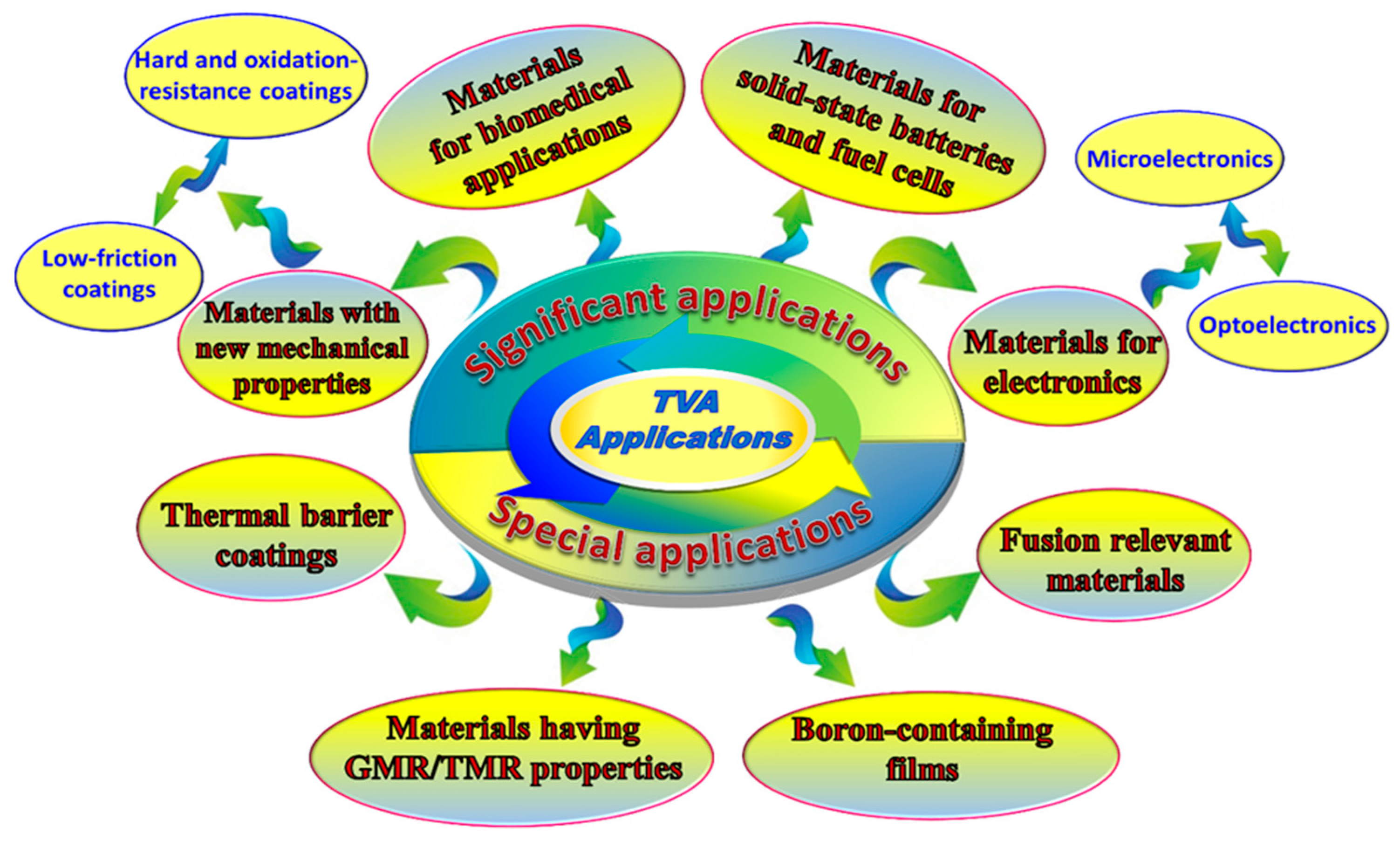
Over more than 25 years since the TVA system invention, the researchers made effort to use all its advantages for efficient development of new materials. The range of TVA applications is very broad; they encompass new mechanical properties (hard coatings, low friction coatings), fusion relevant applications (Be and W coatings), biomedical applications (DLC coatings, etc.), thermal barrier coatings, materials for optoelectronic (CuO, TiO2, ZnO, etc.), materials for microelectronic, materials for solid-state batteries, and materials having giant magnetoresistive (GMR) properties; see Figure 23.
We attempted to present this part of our review as a survey that we organize in groups in accord with the respective application of the new materials. In many cases, however, it is impossible to say that a particular material can be used just for one practical purpose. There are many examples of materials useful for optoelectronic as well as for microelectronic, for biomedical applications and/or low-friction materials, for fusion applications as well as hard or corrosion resistant coatings. We would therefore like to ask the reader to be generous when finding a particular material in one chapter and not in another one.
Many different surface analysis methods have been used in inspecting/estimating the thin film properties, like their structure, roughness, composition, conductivity, hardness, friction coefficient, biocompatibility, and others. They include the optical microscope, transmission electron microscope (TEM), scanning transmission electron microscope (STEM), scanning electron microscope (SEM), focused ion beam technique (FIB), scanning tunneling microscope (STM), field emission scanning electron microscope (FESEM), X-Ray Excited Auger Electron Spectra C KLL (XAES), atomic force microscopy (AFM), energy dispersive X-ray spectroscopy (EDX), wavelength dispersive X-ray spectroscopy (WDS), X-ray photoelectron spectroscopy (XPS), Rutherford backscattering spectrometry (RBS), Resonant Nuclear Reaction Analysis (RNRA), X-ray diffraction (XRD), selected-area electron diffraction (SAED), Fourier-transform infrared spectroscopy, Raman spectroscopy, ellipsometry, nanoindentation, resistivity measurement, wear resistance and corrosion resistance measurements, and others. We assume that the reader is familiar with the principles of these methods and the information that these methods give about the layer under test.

4.1. Materials with New Mechanical Properties

The earlier papers on the thin film deposition by TVA, presented e.g., in [32,50,72] were performed with rather low power in the TVA discharge (anode voltage several hundred volts, discharge current tens of mA). The selection of materials to be deposited by TVA was hence limited to those with rather low melting point. Still the layers of attractive features have been created: the Cu layer in [32,33], the idea of metallization of plastic surfaces by copper films in [72], the MgO film in [50,89], etc.
A new era for the TVA application began with the deposition of layers containing carbon; the first paper describing the carbon film deposited by TVA is [90]. With the directed energy of the energy of carbon ions reaching the substrate of the order 500 eV a nanostructured carbon film was created on NaCl or KCl substrates. Prior to examination of the films by TEM the substrates were dissolved in water. The electron diffraction pattern showed the formation of rhomboidal crystalline structure close to that of DLC in the deposited films. Since no carbon-containing precursor was added, i.e., the film was created purely in the carbon plasma, the hydrogen-free carbon films were obtained [91].
As described in [92] the DLC is a semiconductor with a high mechanical hardness, chemical inertness, and optical transparency. As such, the DLC films have wide applications for hard and corrosion-resistant coatings, optical windows and micro-electromechanical devices (MEMs). From structural point of view, DLC is a metastable form of amorphous carbon with significant sp3 bonding. The sp3 bonding contributes to many of the beneficial properties of DLC that are close to a natural diamond. It is of interest that DLC exists not only as the amorphous carbon, a-C, but also as a hydrogenated alloy, a-C:H. Both these DLC forms have been subsequently created and studied by TVA technology.

4.2. Low-friction Coatings

Carbon-metal nanocomposites. A low-friction coating consisting of a carbon incorporated into silver matrix by TVA is reported in [93]. As a result, the coefficient of friction dropped from that of a bronze substrate ~0.8 down to ~0.35. Similar tribological behavior Ag-DLC films are reported in [94]. The silver/amorphous carbon, Ag/a-C, nanocomposite thin films on Si, glass, and stainless steel OLC45 were deposited and studied [95]. The authors used a single electron gun system and both the C and Ag materials were placed as grains into one tungsten crucible. The soft metal incorporated in the film could act as solid lubricant and, in addition, the silver-containing layers have antibacterial properties. The authors discovered significant differences of the film structure due to the nature of the substrate: they obtained polycrystalline film and cubic CFC Ag (CFC—Cubic Face Centered) with grain sizes of 16nm (on steel) and 23 nm (on Si substrate). The structure of the film deposited on glass was a composite material with large partially graphitized carbon particles covered by small crystalline Ag particles.
A complex study of the properties of the C–Ag, C–Cu, Cu–Sn, and Cu–Al −20–50 nm thick deposited by TVA films produced by TVA is given in [96] and [36]. C–Cu and C-Sn composite films having low coefficient of friction in dry sliding were formed on stainless steel substrates by TVA method. Apart from achieving a similar friction reduction as that quoted above valuable experiences were collected and reported regarding to film smoothness control by process parameters (cathode temperature, electrical power, anode-cathode distance, and the distance between the anode and the substrate). The film structure was defined as polycrystalline metal grains embedded into the amorphous carbon matrix. Further study concerned the low-friction C–Cu and C–Sn films on inoxidable supports and ordinary glass deposited by dual TVA—carbon rod as one anode and metal (Sn, Cu) in a ZrB2 crucible as the second anode [97]. The layer consisted of a thin intermediary layer of Cu or Sn, respectively, on which the thick 2 µm mixed layer was deposited simultaneously by dual TVA. Copper-doped amorphous carbon composite films, a-C(Cu), revealed a minimum value of 0.19 for the friction coefficient [98]. Another attempt to create the low-friction carbon-metal film was performed in [99]; this time the metal incorporated into a carbon amorphous composite film was tin. The friction coefficient of the C–Sn layer on steel substrate reached in dry conditions the values as low as 0.12–0.14 deposited by TVA aluminum-doped amorphous carbon nanocomposite films and reached a minimum value of 0.28 for the friction coefficient. Al-doped amorphous carbon nanocomposite coatings were also deposited by TVA [100].
Nanostructured carbon-nickel coatings prepared by TVA method were reported in [101]. The C-Ni film, and in general, carbon-metal layers act as solid lubricants. The coefficients of friction of the C-Ni coatings measured using a CSM ball-on-disc tribometer were in the range of 0.19–0.27, i.e., 3–5 times lower than that of the uncoated steel substrates. [102] has found the friction coefficients in similar range, 0.15–0.35, in carbon-tungsten nanocomposite films prepared by dual-TVA system. High percentage of tungsten in the carbon film is suitable for plain bearing overlays in the tribological application.
The tribological properties of nanostructured 200 nm thick C–Ag [103] and C–Ti thin films synthesized by TVA method were studied [104,105]. The coated layers consisted of a base layer of about 100 nm of carbon and seven carbon and titanium layers deposited alternatively, at different substrate temperatures values and at different substrate bias voltages. Tribological measurements showed a decrease of the friction coefficient with increase of the normal load. In addition, the films of the known solid-state lubricant molybdenum disulfide, MoS2 were prepared by TVA on glass substrates; they reached the value of the friction coefficient around 0.2 [106].

4.3. Hard and Oxidation-Resistant Coatings

4.3.1. Outstanding Properties of the Deposited DLC Thin Films

The best properties of the TVA technology become evident when depositing layers of materials that were hard or impossible to obtain by other deposition techniques. The first conclusion was that the TVA technology is suitable high quality-smooth, pure, and compact DLC and hydrogen-free carbon film deposition [90]. By its electron gun, TVA provides the needed high value of the energy needed to evaporate/sublimate pure carbon. Moreover, the plasma potential of a TVA plasma is controllable, hence also the energy of ions impinging the substrate. With the intention to increase the bearing lifetime, DLC films were deposited on bronze, iron and bearing steel substrates [107]. The achieved hardness of the DLC films was between 50 and 60 GPa. The film friction coefficient was in the range 0.05–0.1, almost 10 times lower than that of the substrate materials.
The deposition of DLC films is also discussed in [108,109]. Raman spectra of the deposited DLC films have been studied in [110]. The obtained spectra with two peaks, one at 1379 cm−1 and the other at 1558.69 cm−1 (D and G band, respectively) were typical for DLC films with sp2 structure. That confirmed the observation that it is possible to obtain the DLC film with a very high purity by TVA technique. A comparative study of three methods for nanocarbon film deposition was performed: TVA, magnetron sputtering (MS), and filtered cathodic vacuum arc (FCVA) [111]. The film structures have been characterized by X-ray photoelectrons spectroscopy (XPS), Auger electron spectroscopy AES, Raman spectroscopy and transmission electron microscopy (TEM). Amorphous films were obtained with sp3/sp2 abundance ranges between 14% and 41% by all three methods. Crystalline inclusions embedded into the amorphous carbon films were revealed in cases of by TVA and MS deposited samples, which indicate possible applications in wear-protective coatings for magnetic devices. Another possible application of the crystalline carbon thin films could be in anticorrosive coatings for magnetic devices [112].

4.3.2. Surface and Interface Analysis

The surface energy evaluation of H-free DLC thin film deposited by TVA method on different surfaces (Zn and Al foils, stainless steel, glass) was performed in [113]. This study showed that the surface free energy and the wettability of a deposited unhydrogenated DLC film depend strongly on the distance between samples and the point of the ignition of the discharge. The TEM analysis and electrical measurements of carbon thin films on glass and silicon substrates created by TVA can be found in [114]. The techniques used to acquire information were Bright Field transmission electron microscopy (BF-TEM), Dark Field transmission electron microscopy (DF-TEM), High Resolution transmission electron microscopy (HRTEM), Selected Area Electron Diffraction (SAED), and Radial Distribution Function (RDF). The carbon film on both samples could be described using a diamond cubic structure with lattice parameters a = 0.206 nm and c = 0.111 nm.

4.3.3. Refractory Materials and Superalloys

TVA can be used also for deposition of tungsten on graphite substrates [115]. The AFM measurements have proved the smoothness of the deposited films with peak to valley roughness in the range of 20–30 nm. In the ref. [116], an attempt to deposit rhenium (Re) as a part of so-called Ni-based superalloys, e.g., Re–Cr–Ni was reported. Melting point of Re is 3450 K, its boiling point 5903 K. The authors investigated the problem of Re deposition connected with interaction of Re atoms with the hot filament of the electron gun. Since Re has the work function (5.1 eV) greater than tungsten (4.5 eV), and even more than the usually used thoriated tungsten (4 eV), the Re deposited on the hot filament decreased over the deposition time the electron gun power and, consequently the deposition process. The authors finally solved the problem by increasing the filament current to 120 A. That diminished the adsorption of Re atoms on the filament surface and the deposition process could run for the needed time. As a result, Re films of 6 µm thick were deposited on Nb substrates; deposition time was 1 h. The power in the discharge was around 2.5 kW (anode voltage 2 kV, discharge current 1.2 A). In [117] the Re and Re–Cr–Ni films were deposited using: (i) a single discharge in Re vapors and (ii) two independent discharges in Re and Ni/Cr vapors, running in the same vacuum vessel. Such films have a potential application as components of oxidation-resistant coatings for turbine blades. The superalloy Re–Cr–Ni coatings were further studied, including the influence of the different substrates: copper, glass, and ceramic [118,119]. The film composition was inspected by XPS. The thermogravimetric analysis showed that these layers were not subject to surface corrosion in air up to the temperatures 1000 °C. The prepared films were found to be very adherent, pure, and smooth.

4.3.4. Binary and Ternary Combination

The surface density and height distribution of the defects in the layers deposited by TVA and by magnetron sputtering was studied [120,121]. The layers were the multilayers hard coatings of TiAlN, TiN, CrN, and CrN/TiAlN deposited on powder metallurgical high-speed steelASP30, a hot work tool steel H11, a cold work tool steel D2, and cemented carbide. The substrates were polished, ultrasonically cleaned and dried in hot air. Prior to deposition, they were cleaned by ion etching. The surface morphology of the coatings was examined using a 3D stylus profilometer. An SEM in combination with a focused ion beam technique (FIB) and atomic force microscopy (AFM) analyses were performed on selected samples. The authors concluded that defect density depended on deposition time, deposition technique, deposition parameters, substrate position in the vacuum chamber, its orientation, and rotation mode. Any correlation of defect density with coating thickness and substrate material was not found. In ref. [37,38,39,40] were studied silicon-carbide multilayer protective coatings at temperatures up to 1000 °C. Measurements showed that the third layer acts as a stopping layer for oxygen. Characterization of ternary C-Si-Al nanocomposite thin films obtained by TVA presented in [122]. In ref [123,124,125] were studied the nitrogen-doped silicon carbide nanostructures/protective coatings obtained by TVA method. In ref. [126] the prepared hydrogen-free amorphous carbon films doped with Ag, Si, and Mg presented a defined wettability and high corrosion/wear resistance. Ref. [127] studied the properties of binary and ternary Ti based coatings.

4.3.5. Adhesion on the Substrate

One of the problems in the development of the new carbon films production technologies is the bad adhesion to the substrate due to the residual stress during deposition. The adherence of the carbon films could be increased by simultaneous deposition of carbon and several metals: Fe, Cr, Al, and Ni [48]. The stress on the Fe-C layer was inspected by X-ray diffraction on the atomic plane Si (100) by comparing the XRD spectrum of the pure Si substrate with that coated by Fe–C layer. The very low shift and practically no change in the FWHM (Full width at half maximum) of the Si (100) peak allow to conclude that the Fe–C coating do not produce significant stress in the Si wafer. The prepared layers were created and tested for future application in micro-electro-mechanical-systems, MEMS. Properties of the amorphous DLC films on glass and single crystal silicon substrates prepared by TVA have been studied in [128]. The films yielded the hardness 10–14 GPa and elastic modulus 100–125 GPa. Nanometer-sized diamond crystallites were found on all samples, with high sp3 content and relatively low stress. Similar studies were performed in [129] and [130]. The XRD spectra revealed three crystal systems in the deposited layers: graphite in hexagonal form, diamond in cubic form, and tungsten carbide in hexagonal form. The appearance of the latter the authors attributed to the interaction of carbon vapors with the tungsten filament of the electron gun.

4.3.6. Tailoring the DLC Structure

An effort to influence the sp3 content in the DLC films deposited by TVA revealed in [54]. It was found that the following TVA parameters are essential: filament current of the cathode of the electron gun, arc current, applied voltage, and the distance from the anode to the substrate. The authors achieved the sp3:sp2 ration between 20–50% depending on TVA discharge conditions. Application of diamond-like films as nano-abrasives is presented in [87]. Here it was found a direct correlation of the size of the nanocrystallite grains embedded in an amorphous structure with distance of the substrate from the anode. That showed the ability of the TVA technique to synthesize DLC films with a controlled nanoscale roughness and sp3 content. Ref. [131] suggests for estimation of the sp3 content the so-called D-value method.

4.4. Materials for Microelectronics/Optoelectronics

The versatility of TVA technology was reflected in ample applications for optoelectronic and microelectronic. Even if in some cases the below mentioned materials are possible to be created by other techniques, the TVA utilizes its cleanliness, absence of droplets, and easy adjustment of the energy of the ions forming the thin film.

4.4.1. Magnesium-Based Materials

Coatings containing magnesium are interesting for both the opto- and microelectronics. For instance, MgO were deposited by TVA directly from MgO pellets (melting point of MgO is 2852 °C), with the film transparency >94.5% and refractive index of 1.73; values significantly different from those corresponding to bulk material [50]. Pure Mg films were deposited and studied with thickness approximately 200 nm on glass substrate [132]. The films were found to be polycrystalline with preferred orientation (0 0 2). Ref. [133] investigated the MgO/Co multilayers on glass and brass substrates. The films were nanostructures and smooth. The in-TVA synthesis of reinforced magnesium embedded in carbon matrix was performed in [134]. In ref. [135] were deposited Mg-doped GaAs thin films by TVA nanocrystalline with thickness 120 nm on glass. In this work, Mg was suggested as a p-dopant for the GaAs semiconductor with potential application in high-power lasers or red laser diodes. An advantage of using TVA for doping semiconductors resides in the fact that both materials can be placed into one crucible in the requested mass ratio, i.e., the simplest TVA arrangement with one electron gun and one crucible is used. The Mg-doped GaAs thin films showed high transmittance reaching 80% at IR wavelengths and a bandgap value close to that quoted by literature.

4.4.2. Thin Films Deposited as Dielectrics

TVA is also suitable for creating dielectric films. In ref. [136] a capacitor with capacitance 2–4 pF using Ag-Al2O3 composite was created. The ferroelectric lead zirconate titanate (PZT) deposited on ceramic substrates by TVA directly from PZT type powder. The films were nanostructured and smooth and indicated the PZT stoichiometry [137]. Ref. [138] studied the PZT deposited by TVA and pulse laser deposition (PLD). Co-MgF2 thin films with possible applications as thin-film inductors in microelectronic circuits.

4.4.3. Deposition for Solar-Cell Technology

Several works showed also the usefulness of TVA method in solar-cell technology. Ref. [139] prepared the CuInSe ternary compound (CIS) by an electrodeposition process on plastic substrates coated by Ni using TVA technique. CIS has a potential application on absorber material for thin-film solar-cells. Tantalum pentoxide on Si substrates for applications as antireflective or highly reflective film mirrors for solar-cells, for birefringent coatings, or as a component of multilayer interference filters in optical devices was studied [140]. The films were uniform, smooth, with a low roughness and had a rather high refractive index 2.07. Antireflective coatings based on MgF2 are discussed also in [141]; those based on CaF2 in [142]. The BaF2 films with high transparency and low reflections values were produced in [143]. Hard and antireflective carbon thin films on strontium titanate (SrTiO3) reached hardness around 40 GPa [144]. Ex-situ thermal treatment effects on the ZrO2 thin films with regard to their transmittance, refractive index, and bandgap are studied in [145]. The relative changes in transmittance/absorbance due to the thermal treatment were around 10%. From the absorbance, the bandgap was estimated in the range 3.85–4.02, and from that the refractive index of the ZrO2 film between 2.16–2.20. The morphological and optical properties (transmittance, absorbance, reflectance, refractive index) of graphene-doped tin oxide (SnO) deposited by TVA on glass and Si were studied in [146]. A substantial dependence of the optical properties on the substrate material was found and attributed to the different lattice properties of the substrates. The bandgap was estimated from the measured absorption coefficient as explained above, but also measured by fluorescence spectrometer; the data for C-doped SnO was 3.11 eV and 3.33 eV for the glass and Si substrate, respectively; lower than for a non-doped SnO material.

4.4.4. Thin Film Deposition on Special Substrates

In a TVA system, the substrates can be positioned comparatively far from the melted anode material. Consequently, deposition on thermoplastic substrates is possible; usually combined with a deposition on a standard glass or Si substrate. coating the transparent polyethylene terephthalate (PET) substrates by SiO2 and ZrO2 pursued in [147]. Since there is no background gas in the TVA system the both oxides may be deposited “as is”. That means that the oxide is as a material in the crucible is just melted, without danger to change its chemical composition e.g., by oxygen remaining in the discharge vessel. The relatively high deposition rate and hence short deposition time contributed to success of this experiment: the PET substrates were coated without thermal degradation. The work presents and discusses the courses of transmittance and reflectance on the wavelength. Transparent and conductive Ag and Au layers were deposited on PET with the intention to create a material suitable as transparent and conductive film [148]. In addition to reflectance and transmittance measurements also electrical resistivity measurements are performed. Direct deposition of ITO (indium tin oxide, In2O5Sn, typically 90 wt % In2O3 and 10 wt % SnO2) on glass and PET was presented in [149]. Optical properties of ITO thin films on glass and PET were studied by a spectroscopic ellipsometer and UV-vis spectrophotometer. The resistivity of 120nm thick ITO films measured by a four-point method was 1 × 10⁻⁵ Ω.cm and 0.5 × 10⁻⁵ Ω.cm on glass and PET respectively. a similar study with ITO films recently performed when the glass and PET substrates we complemented by silicon [150]. In this work, also the surface free energy was studied by a contact angle method. It revealed the hydrophobic character of the deposited films. The measured conductivity was in a similar range as quoted above. [151] presented SiGe thin films deposited by TVA on glass and PET substrates. SiGe coated samples with low optical bandgaps exhibited low transparency and high absorption.

4.4.5. Gallium-Based Materials

In [152] single-crystal gallium arsenide (GaAs) layers of micron thickness on glass and PET substrates were deposited by TVA in two minutes. GaAs semiconductor is perhaps best known from its application in Gunn diodes used for microwave power generation in radars, however further applications in IR LEDs, laser diodes, solar cells, and optical windows are also important. The GaAs deposition in TVA system reached 13nm/s with elemental composition ratio 45:55% for a PET substrate and 66:34% for a glass substrate. The refractive index estimated from the optical parameters of the layer was 3.64. The authors stress in Conclusion that “… a simple doping procedure is possible in a TVA system …” and “… within the same amount of time multiple deposition processes can be carried out for multi-layer quantum well design …”. Experiments with doping the GaAs semiconductor are presented in: [153] (Mo-doped GaAs on glass substrates), [154] (Sn-doped GaAs on glass substrates), [155] (Zn-doped GaAs on glass substrates), [156,157] (Si-doped GaAs on glass), [158] (C-doped GaAs on glass), [159] (B-doped GaAs on glass), [160] (In-doped GaAs on glass), [161] (Ge- and Mo-Ge-doped GaAs on glass), [162,163] (Co-doped GaAs on glass), [135] (Mg-doped GaAs on glass), [164] (Pb-doped GaAs on glass).
The nitride semiconductors are studied for their potential applications in high-frequency and power electronic devices, such as AlGaN thin films on a glass substrate. The 52 nm thick film showed the p-type conductivity with a bandgap around 3.3 eV [165]. The water contact angle below 90° indicated rather hydrophilic character of the film. Continuation of this study one finds in [166,167]. An alternative study in depositing the AlGaAs films by TVA presents [168]. The InGaN thin film deposited by TVA on GaN and ITO substrate was studied in [169]. In this way, a sandwich layer ITO/GaN/InGaN was created with an average thickness 250 nm. The energy bandgap of the InGaN material was calculated from the measured absorbance data as 2.53 eV.
Gallium nitride (GaN) films studied on glass and PET [170], on Si substrates [171]. When studying the indium gallium nitride (InGaN) layers on glass substrates, [172] has found that “… it is possible to adjust the physical properties of a thin film grown by TVA technique by changing the voltage applied between the discharge electrodes …” (they used 500V and 600V tension). Consequently, a correct discharge voltage may be crucial for reaching the best film quality.
Several types of doped GaN thin films were studied: the Mo-doped GaN [173], the Si-doped GaN films [42], the C-doped GaN [174], the Ge-doped GaN [175], Sn-doped GaN [176] thin films, Ti-doped GaN nanosheets [177] on glass and PET substrates, and compared the film reflectance, refractive index with respect to the type of substrate. In addition, the GaN-based material alloyed with boron, BGaN on glass, and PET substrates. The film was produced in a simple TVA arrangement with one electron gun and one tungsten crucible, where the boron piece and GaN powder were placed [178]. In addition, the properties of undoped and lead-doped GaN films on glass, Si, sapphire, and PET were studied. Hall measurements indicated that the resulting material is n-type semiconductor. Pd doping did not influence substantially the refractive index (undoped GaN 3.45, Pb-doped GaN 3.47) [179]. The last study concerning a doped GaN material was performed in [180], where the Zr-doped thin films deposited by TVA on glass and PET substrates were studied. The film refractive index slightly depended on substrate material (2.55 for the film on glass, 2.60 for the film on PET). Additionally, the film on PET substrate had smaller crystal size, higher resistivity, and higher mobility when compared to that on a glass substrate. The measured conductivity of Zr-doped GaN was n-type.

4.4.6. Deposition of the Semiconductors

Perhaps the largest group of TVA application in opto- and microelectronics concerns the semiconductor technology. [181] coated the Si and glass substrates by zinc sulfide (ZnS). ZnS is a binary compound semiconductor important in photonics research and optoelectronic application. Again, ZnS was deposited directly from the purchased material placed into a tungsten crucible. The refractive index of the 167 nm thick ZnS layer was estimated as 2.05 and the bandgap 3.7 eV. Similar experiment, but with deposition of ZnSe binary semiconductor on a Si substrate was performed in [182]. This time a refractive index of the deposited layer around 2.5 was found. A recent work [183] studies ZnSB, i.e., an alloy of ZnS with boron, deposited by TVA on glass, semi-crystalline PET, and Si substrates. Boron is close to the refractory metals and very suitable candidate for p-type doping in semiconductors. The produced ZnSB films were characterized as wide bandgap semiconductors; from optical properties determined bandgaps were 3.69 and 3.54 eV for ZnSB/glass and ZnSB/PET respectively. Film transmittance reached 90% at 550 nm light wavelength. The author concludes that “ZnSB thin films deposited on three different substrates exhibited almost the same properties”.
Another important semiconductor material, namely from the point of view of its potential application as a transparent conductive oxide is zinc oxide (ZnO) with bandgap 3.27–3.41 eV. ZnO is also non-toxic, abundant in nature, and highly chemical and thermally stable. The crystalline structure can have either cubic or hexagonal symmetry; the phase transition occurs either at rather high pressure or due to an influence of an external magnetic field. Due to the optical and electrical applications, usually, the substrates were glass and PET. The effect of Ge doping on the structural, morphological and optical properties of ZnO:Ge films was studied in [184]. The average crystallite size in the 60–80 nm thick films varied between 11 nm and 30 nm for both substrates; film roughness was greater on PET substrate. Good transmittance was achieved, 90% and 80% on glass and PET substrate, respectively. The bandgap estimated from the optical properties data was somewhat lower for PET substrate (3.43 eV for film on glass and 3.38 eV for film on PET). Further study made in ref [185] concerned Si- doped ZnO (SZO). The film thickness was 35 and 55 nm for PET and glass substrates respectively. The conductivity of the film had ohmic character. Si doping has increased the bandgap to 3.74 and 3.84 eV for glass and PET substrates respectively. Other authors experimented with doping the ZnO by different elements. In [186], the Zr-doped ZnO thin films deposited by TVA on glass, PET, and Si substrates were investigated. The film thickness was approximately 70 nm. Mean crystallite size was 50 nm, 25 nm, and 10 nm for the glass, PET, and Si substrates, respectively. In addition, film roughness was different on the three substrates (20 nm on glass, 5 nm on PET, and 1.5 nm on Si). The paper gives graphs of transmittance, absorbance, and refractive index of the film on the wavelength for all three substrates. Other studies implied Cr-doped ZnO thin films [187] and C-doped polycrystalline ZnO films [188]. In both cases the films were polycrystalline with mean crystallite size 20 nm on both substrates. Transmittance and reflectance of the films was estimated 53% for glass and 16% for PET substrate. Bandgap was determined from the optical properties (transmittance, absorbance) as 3.34 eV. In addition, C-doped ZnO film hardness was estimated as 8 GPa.
In [189,190] TVA was applied for deposition of B-doped ZnO (Zno:B) films on glass and PET substrates. The polycrystalline films were 50 nm/60 nm thick on glass/PET substrate, the crystallite size around 20 nm. Measured transmittance yielded 62%/83%, the refractive index 1.69/1.65, and bandgap 3.2/3.3 eV for glass/PET substrates. Some of the most recent studies were also devoted to this type of semiconductor. In [191] the graphene-doped ZnO (ZnO:Gr) nanocomposite thin films on glass and Si substrates was studied. The Al-doped ZnO films deposited by TVA onto glass, semi-crystal PET, and single crystal Si substrates. Within the films, metal oxide phases (ZnO and Al2O3) and bi-metal oxide phases (ZnAl2O4) were detected [192].
An important semiconductor material is also zinc sulfide (ZnS). It is an n-type semiconductor compound with a bandgap energy 3.73 eV at 300K. Due to its favorable optical properties the ZnS films can be used antireflective coatings for infrared devices and for solar cells. The refractive index of ZnS is rather high, of 2.4. The whole range of potential applications of the ZnS thin films can be found in [193], where the characteristics of ZnS/Si heterojunction diode fabricated by TVA are studied. XRD results showed that the ZnS film has a cubic crystal structure. The fabricated diode demonstrated p-n I-V characteristics in dark at 300K. The photoelectrical properties of ZnS/Si heterojunction produced by TVA were studied in [194]. Photocurrent measurements indicated that the fabricated-device could be used as a photodetector in the UV wavelength range as well as in the longer wavelength range 860–1160 nm.
Among various further semiconductors studied as thin films deposited by TVA plays an interesting role copper oxide in view of the fact that the copper-oxide (Cu2O) rectifiers were used in industry since 1924. CuO thin film is a p-type semiconductor with a tunable bandgap that varies from 1.2 eV to 2.6 eV depending on oxygen content. The authors of ref. [195] studied the In-doped CuxO thin films deposited by TVA onto amorphous glass substrates. The films were 30–60 nm thick, XRD analysis indicated crystallites of Cu, CuO, CuInO2, Cu2O, and CuInO2. The film was found to be a p-type semiconductor. This study was extended in [196], where the structural CuOx film parameters were determined: thickness 66 nm, mean crystallite size 20 nm, average roughness 1.8 nm. The film was polycrystalline, including CuO and Cu crystallites. Refractive index was estimated to be 2.2 at wavelength 632 nm. The most recent work studies the Cr-doped CuxO thin film deposited by TVA on glass substrates [197]. In the film CrO2, Cu2O, Cu, CuO crystallites were found with mean crystallite size 15 nm. Bandgap was determined as 2.0 eV; the deposited film was transparent and had a high dielectric constant.

4.4.7. Deposition of the Titanium Dioxide

Further material interesting for micro- and optoelectronic applications is titanium dioxide, TiO2. Its applications in form of a thin film encompass catalysis, gas sensors, solar cells, optical filters, etc. The authors of ref. [198] produced the TiO2 films by TVA on Indium-tin-oxide (ITO) and fluorine-tin-oxide (FTO) coated glass substrates. The deposited films were identified to be in anatase and rutile crystalline phases. The electrochromic properties of the TiO2 films were studied and the results compared with literature. Transparent titania (TiO2) thin films on glass microscope slide and on a PET substrate were obtained [199]. The authors emphasize rather short deposition time (1 min). The measured optical and surface properties of the coated TiO2 surfaces were closely linked to literature values.

4.5. Beryllium and Tungsten—Fusion-Relevant Materials

4.5.1. The Role of TVA Method in Be Coatings for Fusion Application

The first step in the research and development process for the ITER-like full metal wall of the JET tokamak was to find and assess a suitable coating method of the so-called marker tiles by beryllium. The first attempt to use TVA technique for this purpose is described in [200] as a collaborative effort of Romania, Sweden, and the UK. In order to enable monitoring of Be erosion from tokamak limiters the properties of the marker film had to closely match that of bulk Be. The film was deposited on a so-called high-Z metal interlayer that had to be deposited first on the marker tile. The Be film had to have rather high thickness of several µm, ensure good adhesion and thermomechanical compatibility. The authors have chosen the simple TVA arrangement with one electron gun and one tungsten crucible. In order to avoid impurities of W in the Be film the Be was inserted into the crucible as a solid cylinder (i.e., not in powder form). The deposition rate achieved for Be was around 5 nm/s and for W around 1 nm/s; the substrate was heated up to 400 °C. As a high-Z metal interlayer nickel was deposited. That study was complemented by a spectroscopic study of Be plasma in [83]. Spectroscopically determined electron temperature ranged between 6620K-7900K (0.571 eV–0.686 eV). Numerical simulation of the Be deposition phenomena by TVA method performed [201].
The process of deuterium implantation and retention into the Be films prepared by TVA was studied in [202,203]. A wide range of substrate bias voltages, from −200V up to +700V, was applied in order to modify the morphology of the Be films. Measurements of the film parameters revealed that by applying a negative substrate bias it is possible to obtain adherent, compact and smooth Be films. Since the films were rather thick, the Rutherford backscattering spectrometry (RBS) was applied to study the thickness and composition of each film. The deuterium implantation and retention was studied by a high current ion source.
A linear divertor plasma simulator PISCES-B for studying the erosion yields of Be surfaces prepared by various techniques, a.o. TVA, was applied in [204]. It was found that the erosion yield of the TVA deposited layers was fully comparable with that of the layer deposited by magnetron sputtering. Tungsten films on stainless steel and PK-7 glass substrates were investigated in [88]. Instead of using sintered W rods, which contain high amount of impurities with different dependence of saturated vapor pressure on temperature, a bunch of thin W wires served as an anode material. The obtained W films were pure and dense. Tungsten oxides WO2 and WO3 detected by XPS on the film surface were attributed to reaction with ambient air. A study for Be-W mixed thin films prepared by TVA on a polished steel substrate was presented in [55].
The hydrogen permeability of Be films prepared by TVA were studied in [205,206,207]. Be film samples were deposited on Eurofer steel membranes with exposed area 8.4 cm2. The permeation reduction factor varied on six samples from 14 to 135 (with respect to the bare Eurofer membrane). Lower values the authors explained by microscopic imperfections in the film; some of them were revealed by SEM. In [208] the hydrogen depth profiling in DLC films deposited by TVA by Resonant Nuclear Reaction Analysis (RNRA) was studied. The small hydrogen content, around 5%, in the DLC films was explained by dissociation of water molecules that desorbed from chamber walls during deposition. The influence of nitrogen co-deposition in ITER relevant mixed layers on retention and release dynamics of deuterium was studied in situ in [209]. Nuclear Reaction Analysis (NRA) and thermodesorption spectroscopy were used for analysis of W:Al and W:Be mixed layers deposited by thermionic vacuum arc (TVA) method. Aluminum was tested in view of its potential application as proxy material for Be in experiments regarding D uptake.

4.5.2. Fusion-Related Mixed Layers

Most of the works devoted to fusion-relevant materials study Be and W separately. Alternatively, in [210] there were characterized carbon-tungsten and carbon-beryllium nanostructured films for potential application in divertor coatings by SEM, TEM, and AFM. The films were wear-resistant with rather low friction coefficient 0.15–0.35. A similar study, including the construction of a dual TVA system for simultaneous sequential deposition of carbon and tungsten layers was performed in [211,212]. The layer composition on the substrate position with respect to the C and W anodes and power in each TVA circuit. In [213] tungsten films of thickness from nanometers to micrometers were prepared by TVA and characterized in terms of composition and topography. The W films were pure and contained a thin surface layer of WO3 (oxygen probably coming from rests of water vapors that desorbed from chamber walls at elevated temperature). The authors of [214] prepared the functional fusion related materials by TVA and combined magnetron sputtering and ion implantation (CMSII): W films on Si substrate and Ni films of fine grain graphite (FGG). The analysis of the thickness uniformity was performed by X-ray fluorescence (XRF) and its modifications for thinner layers (< few microns) micro-beam XRF (µ-XRF) and for thicker layers (>40 µm) high-energy XRF (HEXRF). These techniques have been applied on 2D mapping of various functional coatings of tokamak plasma facing surfaces.
Ref. [47] studied fusion-related mixed layers containing tungsten, nickel, and iron in fixed and rotated TVA deposition geometries. The geometrical dependence on a planar substrate using three independent evaporators was studied comparing 2D µ-XRF and compared with theoretical predictions. Pure nanocrystalline Be thin films with thickness approximately 1 µm were deposited by TVA on Si and stainless steel substrates in [78]. The intention of the study was the investigation of the TVA operation parameters on the Be ion energy and plasma ionization degree and on the structural and mechanical properties of the Be thin films. Contrary to [200] the substrates were intentionally unheated, i.e., the deposition proceeded on the substrates at room temperature. Optimum mechanical properties of Be coatings were achieved at rather high TVA discharge voltage values, 1.5–2 kV. It is of interest that also a course of plasma potential in between the TVA electrodes was measured using an emissive probe.

4.5.3. Carbon-Metal Nanocomposites for Fusion Applications

Important group of fusion related materials form the carbon-metal nanocomposites. In [215] they used a dual TVA system for deposition of carbon-aluminum nanocomposite film. The C–Al film have the potential application for the first-wall in ITER tokamak. The film consisted of nanocrystals of size from 2 nm to 50 nm. The C-Al film was characterized by a very low friction coefficient 0.1−0.2 [85] produced by TVA carbon tungsten bi-layer (2.5 µm thick carbon layer on top of 200 nm tungsten film) on fine grain graphite substrate by a dual TVA with two ring-shaped cathodes. The carbon tungsten film was then irradiated by TEWALAS laser system (800 nm wavelength) in order to study the carbon ablation. By observing the XUV emission of the plasma plume due to the ionized ablated material in the spectral range 14–18 nm it was possible to tell the end of the ablation of the carbon layer (after carbon layer ablation the XUV spectrum was characteristic for tungsten). Similar study of interaction of the 250–500 nm thick Be, W, and C layers prepared by TVA with a terawatt TEWALAS laser system is presented in [216], and in [217] the C–W films were deposited on silicon wafer substrates by a dual TVA in order to investigate the influence of TVA operation parameters on the composition of the deposited film. Larger target–substrate distances resulted in smoother films but slower composition variations.

4.6. Materials Having GMR/TMR Properties

Giant magnetoresistance (GMR) or tunneling magnetoresistance (TMR) is a quantum mechanical effect, which arises in thin film structures composed either of alternating ferromagnetic and nonmagnetic layers or in granular-type layers where 3d magnetic metal cluster are uniformly distributed within an insulating matrix. The effect manifests itself as a change in electrical resistance in the presence of a magnetic field.
Sandwich-like layers having GMR/TMR properties. Both types of GMR/TMR structures, sandwich-like as well as granular, can be comparatively easily produced by TVA using the arrangement with two electron guns and two (or more) crucibles with respective materials. In our knowledge, the first effort in depositing the granular layers having the GMR properties is presented in [218]. The work presents the FexCu100−x granular layers with thicknesses about 1000 nm; i.e., a single layer containing two materials. The films were prepared by the simultaneous deposition of Fe and Cu from two anode crucibles heated by two electron guns. As a substrate, Kapton mylar was used. The GMR effect was measured by a relative change of sample resistance ΔR/R when the sample resistance exhibited saturation with a magnetic field. ΔR/R around 38% was obtained in this work for certain samples, however, questions remained about the actual mechanism of the effect with respect to the film properties. The importance of specific deposition conditions and film parameters on the magnetoresistance behavior attempts to explain the work [219]. In this paper, the Fe–Cu and Fe–Co MR systems were prepared by a dual TVA on the Kapton and Si substrates. The elemental composition of Fe/Co and Cu in the film was controlled by a distance from the crucibles with respective materials. Since the crucibles are hot, the same distances define the substrate temperature and hence the size of magnetic clusters by a “real-time annealing”. Both the structural and morphological properties of the deposited films are important with respect to their GMR properties. It was found, that a suitable thermal annealing at the temperature around 410 °C increased the MR effect substantially. That was interpreted as a structural relaxation via, presumably, electron-phonon interactions. The MR film composition consisting of Fe–Cu clusters embedded in the Cu matrix was confirmed by Mössbauer spectroscopy. Similar results are presented in [220].
The authors of [221,222] used for studies of the tunneling magnetoresistance (TMR) effect nanoglobular films where the role of an insulating material played MgO and that of a ferromagnetic one Co. The deposition proceeded in dual TVA and the relative amount of Co in different samples was controlled by the distance of the substrate from the Co crucible; the highest Co content around 35 at. % was achieved at the distance 20 cm (the optimal Co content was found to be 25 at. %). Apart from standard film diagnostic (SEM, HRTEM, EDX) the Magneto-Optic Kerr Effect (MOKE) was applied as a monitor of film magnetic properties. The deposited films were annealed at 300 °C for one hour in high-vacuum conditions. The annealing appeared to decrease the TMR effect in contrast to the nanoglobular systems Co–Cu and Fe–Cu. That was attributed to increasing distances among Co nanograins due to annealing. In [52] the authors studied the 77–200 nm thick granular ferromagnetic Cu/Ni/Fe structures deposited by a triple TVA on glass and silicon wafer substrates. Positive as well as negative magnetoresistive effect of the order +−4.8% was obtained on different samples depending on the mutual weight concentration of Fe and Ni in the samples.
Effect of thickness on magnetic properties of an amorphous thin film prepared by TVA technique from as-cast alloy of nominal composition Fe36Co36B19.2Si4.8Mo2W2 were studied in [223]. The bulk magnetic properties of thin films (the hysteresis loops) were examined at room temperature using an ADE Magnetics EV9 vibrating sample magnetometer (VSM) with maximum magnetic field strength of 1750 kA/m. Measurements showed that the bulk coercivity increases with increasing the film thickness. The grain size in MgO-Co multilayers prepared by TVA studied the work [224] as materials with potential application in spintronic devices. Potential technological applications in thin-film inductors for power converters for microprocessors can have also the Co–MgF2 granular layers deposited by TVA on glass and Si substrates and investigated in [225]. This material represents also a metal-insulator granular system composed of grains of a ferromagnetic element immersed in an insulating matrix. A TVA system with two ring-shaped cathodes and two crucibles: a W one for Co evaporation and a TiB2 one for MgF2 evaporation. Smooth, 200 nm thick, granular Co–MgF2 films were produced and comprehensively analyzed by XRD, TEM, and AFM. Structural and magnetic properties of nanostructured Co deposited by TVA on Si (111) surfaces is studied in [226,227]. The film magnetic properties were examined by a vibrating sample magnetometer (VSM). This work was a collaborative effort of Université Paris 13, France, NILPR Magurele, Romania, and Université d’Annaba, Algeria.
TVA method was further successfully used in obtaining two types of FeCo based structures in [53]. One, a GMR combination where the ferromagnetic grains of iron and cobalt were embedded in a pure copper matrix and the other one, a combinatorial GMR + TMR structure which contained as a ferromagnetic material the FeCo alloy embedded in a nonmagnetic semi-conductive copper–magnesium oxide matrix. The relative GMR effect varied, with respect to the relative elemental concentration from 1.3% up to 26.4% for the first type of material and from 4.5% up to 19% for the FeCo + Cu + MgO structure at room temperature. At 40 °C the highest ΔR/R value was 80% and 69% for material of the former and latter type, respectively. The magnetoresistive effect obtained by TVA prepared CuNiCo nanogranular thin films for the studied samples varied from 0.6% to 19% in respect sample structure and temperature for a constant magnetic field describes the work [51]. The optical, surface, as well as magnetic properties of the Ti-doped GaN nanosheets deposited by TVA on glass and PET substrates were studied in [180]. This material is usually studied as a transparent conductive material, but it shows also ferromagnetic properties.
Sandwich-like GMR structures, so-called spin valves, were first produced in dual TVA system in [228]. The spin valve structures consisted of an antiferromagnetic layer composed of Fe and Mn in the same mass proportion, and of another layer composed of Fe and Ni permalloy). The percentage of Fe and Ni in this layer was varied in order to achieve minimum coercive force thus enabling easy re-orientation of the magnetic domains even at low magnetic fields. In this work, the mechanical tests of the films were made using nanoindentation and SEM and the study was then extended in [229]. In order to change the relative percentage of Fe and Mn in the sample the Fe-Mn binary layers were alternatively obtained using the single TVA with a Fe-Mn alloy pre-prepared in the requested ratio. The experiments indicated that smoother systems are obtained by depositing NiFe layer over the FeMn layer than in the inverted deposition sequence. The tiny changes of the magnetic field in the samples due to applied magnetic field between −0.15T and +0.15T (hysteresis loops) were measured by SQUID magnetometry and MOKE.
The copper-nickel magnetoresistive multilayers were prepared in [230]. Successive layers of Cu and Ni were deposited on silicon substrates by a dual TVA with two tungsten crucibles containing Cu and Ni respectively. The deposited films were characterized by EDAX and TEM. An appearance of tiny impurities of Zn and Ag in the deposited films was discussed. For deposition of GMR/TMR multilayers on glass and Si substrates a triple TVA system, i.e., three combinations of electron guns and crucibles arranged in one vacuum chamber were applied in [67]. One TVA was envisaged only for Cu deposition since Cu was used as a non-magnetic metallic interlayer. The other two electron guns worked with several crucibles each arranged on a turntable that contained the MgO, Co, Ta, and Ag. Different voltages/discharge currents were used for each electron gun/crucible combination. In the course of deposition of a particular material, the unused crucibles were shielded by a molybdenum plate. In such manner, sandwich-like structures were deposited in-situ without breaking vacuum. Apart from SEM the MOKE diagnostic was used together with measurements of electrical resistance of the final multilayer samples in magnetic files between −0.4T and +0.4T. The sandwich structure consisted of Ta film deposited directly on the substrate, of the second sandwich layer containing combination of six Co films separated by layers containing Ag and MgO, and of the final Ta structure completing layer. For the GMR/TMR measurement the structure started with a Cu layer that made an electrical contact. By changing the substrate position with respect to the respective anode the weight percentage of materials in the film was controlled. The resistance of the samples was measured by four-point method. Both the positive TMR effect (decrease of resistance with increasing the magnetic field) and the negative TMR effect (vice-versa) was observed; the relative ΔR/R was about 28%. Similar sandwich structures Co–Cu–Co on glass, Si and ceramic substrates were characterized in [231], and in [46]. A summarizing description of the TVA method and its uses in both simultaneous and alternate thin film deposition is presented in [232].
Multilayer structures of Cu–Co–Cu-Fe deposited by TVA were studied in [44,45]. The structure of the thin films contained 16 layers (totaling 180 nm), structured in 4 sets of 4 successive layers: Cu, Co, Cu, and Fe. The thicknesses of the Co and Fe layers was 10 nm each and the thickness of Cu layer was 12 nm. This work presented excellent cross-sectional SEM images of the deposited sandwich structures at magnification 200,000. The detected relative (negative) GMR effect was −31% at magnetic field induction 0.4 T and temperature 340 K. The GMR effect was attributed to the nanoscale film size. MOKE measurements confirmed that the multilayer structure had ferromagnetic properties.

4.7. Materials for Biomedical Applications

Many of the materials already mentioned, for instance those with low-friction, have found applications in biomedicine. As examples, they may serve as coatings on hip joints, stents, or dental implants. However, the materials used in this area must also be biocompatible, not toxic and must not cause allergenic reactions. They should be flexible and durable, have the high tensile strength, proof strength, low density, and low elasticity modulus.

4.7.1. Dental Implants

The authors of [233] studied the materials suitable for dental implants and compared the DLC-coated materials with not coated ones. As substrates/specimens the 3 mm in diameter and 100 mm long laminated titanium rods were used; the DLC coatings were performed by a TVA system. The deposition continued until the thickness of the DLC film reached 20nm. Then the rod was rotated by 10 degrees and another 20 nm thick film was deposited. Since for dental implants the mechanical properties are crucial, the samples were tested for bending and tensile deformation. The bending strength of coated specimens slightly increased with respect to the uncoated ones; consequently, the dental implants made from Ti with carbon coatings will resist better than the uncoated ones. The tensile tests indicated increased elasticity of the DLC-coated specimens; this could lead to the increase of implant’s lifetime. A similar study in coating Ti rods by DLC films was performed in [234]. The deposition method was the same: 20 nm film was grown, then the rod rotated by 180 degrees and another 20 nm layer was grown. The bending strength and elasticity of the samples coated by a DLC film was found higher and close to the bone features than that of uncovered samples. Better elastic behavior was also found in tensile tests for DLC coated specimens.

4.7.2. Implantable Medical Devices

It is well known that devices containing nanocrystalline silver and platinum may provide improved antimicrobial and anti-inflammatory properties for implantable medical devices. That is why the metal-containing amorphous carbon (a-C:Me) and the tetrahedral (diamond-like) amorphous carbon (ta-C:Me) were studied in [235]. A dual TVA system was used with two electron guns and two sources of material: a carbon rod of 10 mm in diameter and 150 mm in length and a TiB2 crucible containing silver. As substrates, the steel polished disks and the disks from BK7 optical glass; both with diameter 25 mm were used. The surface diagnostic of the 2 µm thick films revealed the cubic crystalline phase of the Ag in the layer with a mean crystallite size 15–19 nm. The tribological analysis indicated a rather low friction coefficient for films containing 32.2% of Ag.

4.7.3. Biomedical Coatings

While for hard-coatings purposes are advantageous the hydrogen free carbon films, for the biomedical applications the a-C:H films are more suitable. Hydrogenated carbon films have been proved to be very useful for biomedical coatings (hip joints, stents, actuators, etc.) and biosensors, they are anticorrosive and chemically stable. However, the density and hardness of these films are lower than for hydrogen free carbon films; that is why they are included in so-called soft films category. The amount of hydrogen in the film is best controlled by using the G-TVA for film deposition. The a-C:H thin films with precise characteristics at the nanometric scale presents the work [51]. Smooth and pinhole-free a-C:H films were deposited by G-TVA and reported in [60]. The films exhibited good fracture toughness, wear resistance and good adhesion to silicon and carbon substrates. Their hardness and elastic modulus were found in the range 6-24 GPa and 64-163 GPa, respectively.

4.7.4. Antibacterial Materials

Metal ions are antibacterial materials. The antibacterial effects of metal ions are related to their ionization energy and to their group number in the periodic table. Atoms with lower ionization energy can cause stronger antibacterial effect; the higher the group number the lower the antibacterial effect. Antibacterial properties of nano-layered Au, Ag, and Al films deposited by TVA on flexible organic substrates were studied in [236]. The antibacterial properties of the coatings were examined using Escherichia coli (ATCC 25922) bacteria. The contact time was 3 h and the antibacterial properties were determined after 24 h. The authors state that the antibacterial effects of metal ions are related to their ionization energy and to their group number in the periodic table. Atoms with lower ionization energy have stronger antibacterial effect; atom in higher group have weaker antibacterial effect. The results showed that the antibacterial effect was strongest with Ag films (ionization energy 7.58 eV, group 11), followed by Au (ionization energy 9.23 eV, group 11) and Al (ionization energy 5.99 eV, group 13) films. All the coated organic substrates were chemically inert and showed antibacterial property.
Adding antibacterial properties to implants can confer local therapy and poses no risk of inducing development of resistant strains. The antibacterial properties and corrosion resistance of the silver-doped DLC coatings on titanium (Ti) were studied in [237]. The work evaluated the composite silver-hydrogen-free DLC film deposited on a Ti substrate using a dual target TVA plasma. The TVA arrangement was that of a ring-shaped cathode and two crucibles/anodes with carbon and Ag materials. The results related to surface characterization report good electrochemical stability (corrosion resistance) and excellent antibacterial effect against Staphylococcus aureus of the silver doped DLC coatings.
While the DLC films proved their suitability in a variety of in vivo biomedical applications, some in vitro studies focusing on DLC films demonstrate that cellular behavior on DLC is cell type specific. The study in [238] evaluated the interaction between DLC substrates and keratinocyte stem cells isolated from oral epithelia. The work demonstrated that DLC films are biocompatible with oral keratinocyte stem cells. Moreover, that cell proliferation, viability and colony forming efficiency depended on the physical attributes and chemical composition of DLC films. This work was a collaborative work of eight Romanian Universities and research institutes.

4.7.5. Sensors for Biomedical Analysis

A novel disposable stochastic sensor for biomedical analysis was developed in [239]. The aim was to simplify the detection of Interleukin-6 (IL-6), which is a biomarker for cardiovascular and several other diseases. The new sensors were based on a special fabric (textile) material. The veil textile was covered first by silver that created an electrical contact. Then the active side of the veil was covered by a DLC layer by an anodic arc (TVA) plasma. The technology utilized the benefit of TVA system, namely that even the temperature-sensitive substrates may be deposited. The sensors showed high sensitivity (Il-6 detection limit 1 fg/mL). The sensors were developed as disposable, they could be used 1 day only. Nevertheless, they have potential application for early diagnosis of cancer, inflammation, and obesity from blood samples. Disposable, carbon-modified paper based sensors for biomedical analysis were reported in [240]. The sensors were based on carbon thin films deposited on adsorbent and glossy papers modified with nanostructured material. The authors performed qualitative and quantitative tests of the new sensors. The results confirmed that they could be used as disposable sensors for biomedical analyses with high reliability.

4.8. Materials for Solid-State Batteries and Fuel Cells

In our world of mobile phones, tablets, and other easy portable electronic, acquire an increasing importance the batteries with low thickness. Batteries like this use a solid-state electrolyte. As follows from literature, see e.g., [241], the ideal solid-state electrolytes must have a high ionic conductivity. Li3PO4 all solid-state electrolyte has highest ionic conductivity 4 × 10⁻⁷ S/cm at 25 °C, it is electrochemically stable and represents therefore a good separator for thin film battery. The transparent nano layered Li3PO4 coatings on bare and ITO coated glass by TVA presents [242].

4.8.1. Thin Rechargeable Batteries

In the work [243] there are for the first time presented attempts to manufacture thin rechargeable batteries using the TVA and RF (Radio Frecquency) sputtering methods. Even if not mentioned in this short conference abstract, the authors attempted to manufacture this type of electrolyte; as follows from their works mentioned below.
The technology of producing the transparent all-solid electrolyte by RF magnetron sputtering is described in [244]. As a magnetron target material, a 5 cm diameter disk from Li3PO4 was used. The deposition proceeded in a pure argon RF discharge. The resulting Li3PO4 films were about 100 nm thick, homogeneous, compact and hydrophylic. The authors concluded that “… Li3PO4 was more proper solid state electrolyte compared to LiPON (lithium phosphorus oxynitride) due to absorption edge of sample is not in visible and near infrared region.”

4.8.2. Lithium-Based Materials

Above quoted success stimulated further research in this field. The application of TVA technology for production of Li3PO4 all-solid electrolyte is for the first time in detail described in [245]. This technique yielded transparent solid-state electrolyte in a very short production time. The TVA configuration was that with one electron gun and one molybdenum crucible, where the Li3PO4 target material was placed. The deposition process lasted 85 s with a deposition rate of 4.53 nm/s. The resulting film thickness measured by Filmmetrics F20 device was 385 nm. The film was homogeneous, highly compact and void-free. The XRD showed the complete amorphous nature of the film. From the optical parameters (transmittance, reflectance, absorbance) determined the optical band gap ranged between 8.1 eV and 9.3 eV. The authors concluded that “the obtained results are suitable in secondary type battery applications.”
In order to study the effect of two different production methods on the thin film battery characteristics the authors of [246] produced the Li3PO4/LiCoO2/ITO/glass (LPO/LCO/ITO/glass) structures (half-cell battery designs) by a combination of TVA and RF sputtering. At first, the LCO layers were deposited onto ITO coated substrates by RF sputtering. Then the LPO electrolyte layer was deposited either by RF sputtering or by TVA method. No thermal treatment has been applied after the thin film deposition process. The high transparency cells were produced by both methods. It was found, that the Li ratio in the half-cell produced by RF sputtering was higher than that produced by TVA due to the influence of RF power. The porous structures were better obtained by TVA technique. Consequently, a combination of both methods provided a suitable technology for production of LPO/LCO/ITO/glass thin film battery half-cells.

4.8.3. Platinum-Based Materials

The carbon-platinum catalysts for fuel cell technology are studied in [247]. In order to prepare nanostructured carbon based films (C—Glass + Pt) on glass for use in the anode and cathode parts of fuel cells, the TVA method was used in one electronic gun configuration. First the glass substrate was covered by a carbon film with about 50 nm thickness. C-covered glass samples were then layered by a very thin Pt layer 3.2–4 nm thick. At such low thickness, Pt was deposited in the form of isles. The thorough examination by several surface-analysis methods revealed that the C-glass+Pt films have a uniform morphology and amorphous structure. Electrical analysis showed certain magnetoresistive effect (up to about +− 7%) that was attributed to Pt film. This work continued in [248] by a study of PtNiPd thin films on glass, which are relevant as Platinum Group Metal alloy fuel cells catalysts. This time a TVA in a three gun and three crucible configuration was applied. The HRTEM records showed the spherical Pd nanoparticles about 5 nm in diameter nucleated into PtNi matrix as intended. The PtNiPd films were found smooth, homogeneous, and exhibited rather low friction coefficient between 0.3–0.4 depending on normal force and very low mechanical attrition rate.

4.9. Thermal Barrier Coatings

Thermal barrier coatings (TBC) are key technology for advanced gas turbine materials to provide thermal insulation from the hot gas stream, because of their outstanding thermomechanical properties, see e.g., [249]. The TBC structure is usually composed of two main layers; an aluminum-rich bond coat and a ceramic top coat as a thermal insulator.

4.9.1. Nickel-Based Alloys

The work [250] studies the nickel-based alloys that are highly efficient at elevated temperatures, exhibit surface stability and corrosion and oxidation resistance. Nickel-based alloys contain materials such as ruthenium (Ru), rhenium (Re), titanium (Ti), cobalt (Co), chromium (Cr), and others. The paper [250] studies mixed alloys of Re, Ni, Cr prepared on silicon, graphite, glass, and stainless steel substrates using multiple (three) TVA sources with ring shaped cathodes configuration and three rod-shaped sources of the respective material. In this configuration, the plasma does not fill up the whole vacuum chamber, but remains concentrated above the cathode. That enabled (i) monitoring of the rates of deposition of all three materials separately and (ii) variation of the relative elemental concentration in the film by changing the distance from individual anode-cathode system. As explained in Introduction, the TVA system enables independent variation of the arc voltage that defines the plasma potential and hence the energy of ions impinging on the substrate, and of the arc current that controls the rate of deposition. In this system, the discharge voltages and currents for every TVA source were kept constant during deposition. The analysis of the resulting layers was performed by a micro X-ray fluorescence (micro XRF) method. In order to calibrate the relationship between the micro-XRF photon counts and the atomic concentration in the films the films with precisely known thicknesses of individual materials Ni, Re, an Cr were prepared. The distribution of atomic concentration (atoms per square cm) in the films with respect to the width and length coordinate within the rectangular substrate was calculated, measured by micro-XRF and the results were compared. The measured distributions of atomic concentrations corresponded qualitatively quite well to the calculated values.

4.9.2. Carbon-Titanium Multilayer Films

Carbon-titanium multilayer films on silicon substrates were prepared in [104]. The final film thickness was up to 400 nm. First, a 100 nm carbon layer was deposited followed by seven carbon and titanium layers deposited alternatively. A dual TVA with two ring-shaped cathodes and two rods with respective material (C, Ti) as anodes was used. Different samples were manufactured by variation of the substrate temperature between 0 °C and 400 °C and by variation of the negative substrate voltage up to −700V. Low deposition rate was applied in order to obtain layers with a precise thickness. Apart from a study of the GMR feature discussed above, a thermal conductance of the multilayers was computed using the measured electrical conductivity. It appeared that such multilayer structures are also good thermal isolators.

4.10. Boron-Containing Films

Boron has at atmospheric pressure melting temperature 2076 °C and boiling temperature 3927 °C. It is used as a compound element in a large number of chemicals. In addition, the observed superconductivity of magnesium diboride (MgB2) has generated an increased interest in boron processing. From the point of view of its high melting point, boron can be observed as close to the refractory metals. It was therefore a good candidate for a test of TVA abilities from the very discovery of the TVA technique. To the best of our knowledge, the first paper describing the boron film deposition was [251], presented on the 4th International Conference on New Research Trends in Material Science ARM-4. The film analysis by various techniques showed that the films were of high quality. The evaporation process was quite stable, even if, in view of the high melting point of boron, high TVA discharge voltages and currents had to be used. The first on the boron deposition problems discovered subsequently was already detected: the boron carbide production at carbon crucible due to its reaction with evaporated boron. The uniqueness and complexity of boron film production by TVA was also the reason for placement of this technology into a separate paragraph.
As it is clear from its high melting point the power needed to reach sufficient concentration of boron atoms in TVA vacuum chamber is rather high. The authors of [41] needed almost 4 kV at the cathode current 0.4 A in order to ignite the discharge; after ignition, the discharge voltage dropped down to approximately 1.5 kV at discharge current around 1 A: power deposited at the carbon crucible with boron was around 1.5 kW during deposition. In order to inspect the films by TEM, the films were deposited on KCL substrates that were later dissolved in water. As a drawback, the authors quote the rather low deposition rate and the reduced lifetime of the tungsten filament-part of the TVA electron gun. The use of an indirectly heated cathode in the TVA electron gun was suggested.
The paper [252] as the first one pointed out the problems connected with the boron film deposition by TVA. The first, already mentioned problem rests in finding a material suitable for TVA crucible. At high temperatures, necessary for evaporating boron in sufficient quantities, compounds like boron carbide and tungsten carbide are formed resulting in the failure of either crucible or electron gun cathode or both. In the work [252], various materials for TVA crucibles were tried, solid tungsten crucible, crucible formed by tungsten wires, carbon crucibles with different shapes, glassy carbon, molybdenum, boron rod, etc. Metallic crucibles failed since the alloys of boron with the respective material, W, Mo were formed and introduced impurities into the deposited films. As a result, tungsten wires and glassy carbon crucible were found acceptable for boron deposition. Even so, the tungsten filament lifetime was too short, several minutes. The boron film surface appeared smooth with roughness under 10 nm, the deposition rate was small, around 10 nm/s.
Properties of the boron films deposited by the above-described method were examined in [253]. XPS analysis indicated 68 at. % of boron, the impurities being carbon (11 at. %), nitrogen (8 at. %), oxygen (12 at. %), and silicon (1 at. %). From the measured optical properties (transparency, reflectance, absorbance) the optical bandgap of the produced boron film was estimated as 2.5 eV.
An attempt to produce the superconducting material MgB2 was presented in [253]. In this work, a combination of magnetron sputtering and TVA was applied. The Mg films were produced by a thermal evaporation and DC magnetron sputtering, the boron layers by TVA; the final layer composition was Mg/B/Mg. The used substrate was glass covered by a thin chromium layer for better adhesion of the subsequent films. The vacuum chamber therefore contained three technological parts: thermal evaporator for the first Mg layer, TVA system with a tungsten crucible, and a magnetron cathode with Mg as a target material. During thermal evaporation, the pressure was kept low, around 10−4 Pa, the DC magnetron discharge operated in argon at pressure around 0.3 Pa. This pressure was adjusted dynamically by controlling the pumping speed at argon flow 20 sccm. During the Mg target pre-sputtering (in order to remove any contamination on the target surface), a shutter movable via a vacuum feed through shielded the sample. The final layer structure was composed of two 500 nm thick Mg films separated by 1 µm thick boron film. After two-step annealing at 650 °C the resulting films exhibited an onset of the superconducting transition at the temperature approximately 33 K with a transition width 6 K; the zero resistivity was reached at 27 K. The paper [43] studies the boron evaporation property before TVA ignition. Further, XPS analyses of boron thin film deposited by TVA are presented.

5. Conclusions

Figure 24 shows the number of scientific papers related to TVA technology with respect to the year of publication. It is evident that during the last 25 years, the thermionic vacuum arc (TVA) technology has proved its viability in fundamental science as well as in practical applications. The TVA system simplicity, cleanliness, easy control of ion energy, creation of alloys with controllable percentage of components, possibility to form sandwich-like multilayer structures, 2D nanomaterials, and superior film properties are just a few advantages of the deposition of thin films of different materials by TVA. The research encompassing TVA technology contributed in many fields that are beneficial for mankind: mechanical engineering, optoelectronics, biomedicine, fusion, batteries, thermal barriers, superconductivity. Applications of TVA stimulated world-wide scientific collaboration, the research results were appreciated by several patents. Without doubt, the TVA technology will develop in the future and bring objects that will further ease the human life.

Author Contributions

Methodology: R.V., M.T.; software, V.D., A.M.; validation, R.V., M.T.; formal analysis, R.V., M.T.; investigation, R.V., M.T., V.D.; resources, R.V., M.T.; writing—original draft preparation, R.V., M.T.; writing—review and editing, R.V., M.T., V.D.; visualization, R.V., M.T., A.M., P.K.; supervision, R.V., M.T.; project administration, R.V., M.T.; funding acquisition, R.V., M.T., V.D. All authors have read and agreed to the published version of the manuscript.

Funding

This research was funded by Ministry of Research and Innovation, CNCS–UEFISCDI, project 70/2017, PNCDI III and by the Czech Science Foundation, project No. 19-00579S.

Conflicts of Interest

The authors declare no conflict of interest.

References

  1. Boxman, R.L.; Philip, J.M.; David, M.S. Handbook of Vacuum Arc Science and Technology: Fundamentals and Applications, 1st ed.; William Andrew Publishing/Noyes Publications: Park Ridge, NJ, USA, 1995. [Google Scholar]
  2. Lafferty, J.W. Vacuum Arcs: Theory and Practice, 2nd ed.; John Wiley: Hoboken, NJ, USA, 1980. [Google Scholar]
  3. Anders, A. Available online: https://escholarship.org/uc/item/33n1m86d (accessed on 26 February 2020).
  4. Matthews, A. Plasma-based physical vapor deposition surface engineering processes. J. Vac. Sci. Technol. A 2003, 21, S224–S231. [Google Scholar] [CrossRef]
  5. Snaper, A.A. Arc Deposition Process and Apparatus. U.S. Patent 3,625,848, 7 December 1971. [Google Scholar]
  6. Sablev, L.P. Apparaturs for Metal Evaporating Coating. U.S. Patent 3,793,179, 19 July 1971. [Google Scholar]
  7. Bradley, D.E. Evaporated carbon films for use in electron microscopy. Br. J. Appl. Phys. 1954, 5, 65–66. [Google Scholar] [CrossRef]
  8. Kesaev, I.G. Cathode Processes of an Electric Arc; Nauka: Moscow, Russia, 1968. (In Russian) [Google Scholar]
  9. Rakhovskii, V.I. Physical Foundations of Switching Electrical Current in Vacuum; Nauka: Moscow, Russia, 1970. (In Russian) [Google Scholar]
  10. Aksenov, I.I.; Belous, V.A.; Padalka, V.G. Apparatus to rid the plasma of a vacuum arc of macroparticles. Instrum. Exp. Tech. 1978, 21, 1416–1418. [Google Scholar]
  11. Karpov, D.; Efremov, D.V. Arc sources of metallic plasma for coatings in vacuum and for high speed vacuum pumping. Vacuum 1995, 46, 825–826. [Google Scholar] [CrossRef]
  12. Bunshah, R.F. Deposition Technologies for Films and Coatings: Developments and Applications, 1st ed.; Noyes: Park Ridge, NJ, USA, 1 June 1982. [Google Scholar]
  13. Mattox, D.M. The Foundations of Vacuum Coating Technology; Noyes Publications: Norwich, NY, USA, 2017. [Google Scholar]
  14. Boxman, R.L.; Zhitomirski, V.N. Vacuum arc deposition devices. Rev. Sci. Instrum. 2006, 77, 021101. [Google Scholar] [CrossRef]
  15. Krutenac, R.C.; Gesick, W.R. Vapor Deposition by Liquid Phase Sputtering. J. Vac. Sci. Technol. 1970, 7, S40–S43. [Google Scholar] [CrossRef]
  16. Dorodnov, A.M.; Kuznetsov, A.N.; Petrosov, V.A. New anode-vapor vacuum arc with a permanent hollow cathode. Sov. Tech. Phys. Lett. 1979, 5, 418–419. [Google Scholar]
  17. Bunshah, R.F.; Raghuram, A.C. Activated Reactive Evaporation Process for High Rate Deposition of Compounds. J. Vac. Sci. Technol. 1972, 9, 1385–1388. [Google Scholar] [CrossRef]
  18. Bunshah, R.F.; Juntz, R.S. High-rate evaporation/deposition processes of metals, alloys, and ceramics for vacuum metallurgical applications. In Transactions of the Vacuum Metallurgy Conference; American Vacuum Society: New York, NY, USA, 1965; p. 200. [Google Scholar]
  19. Bunshah, R.F. High-rate evaporation/deposition processes of metals, alloys, and ceramics for vacuum metallurgical applications. J. Vac. Sci. Technol. 1974, 11, 814–819. [Google Scholar] [CrossRef]
  20. Bunshah, R.F. High Rate Deposition of Carbides by Activated Reactive Evaporation. U.S. Patent 3,791,852, 12 February 1974. [Google Scholar]
  21. Ehrich, H. The anodic vacuum arc. I. Basic construction and phenomenology. J. Vac. Sci. Technol. A 1988, 6, 134–138. [Google Scholar] [CrossRef]
  22. Ehrich, H.; Hasse, B.; Mausbach, M.; Müller, K.G. The anodic vacuum arc. II. Experimental study of arc plasma. J. Vac. Sci. Technol. A 1988, 6, 2499–2503. [Google Scholar] [CrossRef]
  23. Ehrich, H.; Hasse, B.; Mausbach, M.; Müller, K.G. The anodic vacuum arc and its application to coating. J. Vac. Sci. Technol. A 1990, 8, 2160–2164. [Google Scholar] [CrossRef]
  24. Ehrich, H.; Hasse, B.; Mausbach, M.; Muller, K.G. Plasma Deposition of Thin Films Utilizing the Anodic Vacuum Arc. IEEE Trans. Plasma Sci. 1990, 18, 895–903. [Google Scholar] [CrossRef]
  25. Ehrich, H. Method and Apparatus for Evaporating Material in Vacuum. U.S. Patent 4,917,786, 16 February 1990. [Google Scholar]
  26. Popescu, I.; Brandus, L.; Moldovan, C.; Musa, G. On the diffusion theory of the low-voltage arc plasma. Br. J. Appl. Phys. 1966, 17, 129–131. [Google Scholar] [CrossRef]
  27. Musa, G.; Betiu, N.; Mustata, I.; Baltog, A.; Popescu, A. Low Voltage Arc Welding in Vacuum. Rev. Roum. Phys. 1983, 28, 907. [Google Scholar]
  28. Musa, G.; Baltog, A.; Popescu, A.; Betiu, N.; Mustata, I. Electrical and Spectral Characteristics of a Heated Cathode Discharge in Metal Vapors. Beitr. Plasmaphys. 1986, 26, 171. [Google Scholar] [CrossRef]
  29. Musa, G.; Baltog, A.; Popescu, A.; Betiu, N.; Mustata, I. Possible High Power Laser Construction Using a New Discharge Type-Heated Cathode Discharge in the Copper vapours Continuously Evaporated from the Anode. Beitr. Plasmaphys. 1987, 27, 431. [Google Scholar] [CrossRef]
  30. Musa, G.; Popescu, A.; BaItog, A.; Betiu, N.; Mustata, I. Hot Cathode Pulsed Discharge in Copper Vapors from a Melted Anode. Rev. Roum. Phys. 1987, 32, 869. [Google Scholar]
  31. Musa, G.; Mustata, I.; Dinescu, G.; Bajeu, G.; Raiciu, E. Evaporation Source for Deposition of Protective Layers inside Tubes. Jpn. J. Appl. Phys. 1992, 31, 2869–2871. [Google Scholar] [CrossRef]
  32. Musa, G.; Ehrich, H.; Mausbach, M. Studies on thermionic cathode anodic vacuum arcs. J. Vac. Sci. Technol. A 1994, 12, 2887–2895. [Google Scholar] [CrossRef]
  33. Musa, G.S.; Ehrich, H.; Schuhmann, J. Pure Metal Vapor Plasma Source with Controlled Energy of Ions. IEEE Trans. Plasma Sci. 1997, 25, 386–391. [Google Scholar] [CrossRef]
  34. Vladoiu, R.; Musa, G.; Mustata, I. Thermoionic vacuum arc—A new method of thin film deposition. J. Optoelectron. Adv. Mater. 2003, 5, 325–330. [Google Scholar]
  35. Kadoun, A.; Belkorissat, R.; Khelifa, B.; Mathieu, C. Comparative study of electron beam-gas interaction in an SEM operating at pressures up to 300 Pa. Vacuum 2003, 69, 537–543. [Google Scholar] [CrossRef]
  36. Ciupina, V.; Vladoiu, R.; Mandes, A.; Musa, G.; Lungu, C.P. TEM investigation of the C-Me multilayer nanocomposites deposited by Thermionic Vacuum Arc (TVA) method. J. Optoelectron. Adv. Mater. 2008, 10, 2958–2962. [Google Scholar]
  37. Ciupina, V.; Vladoiu, R.; Lungu, C.P.; Dinca, V.; Contulov, M.; Mandes, A.; Popov, P.; Prodan, G. Investigation of the SiC thin films synthetized by Thermionic Vacuum Arc method (TVA). Eur. Phys. J. D 2012, 66, 99. [Google Scholar] [CrossRef]
  38. Ciupina, V.; Lungu, C.P.; Vladoiu, R.; Epure, T.D.; Prodan, G.; Rosca, C.; Porosnicu, C.; Jepu, I.; Belc, M.; Prodan, M. SiC multi-layer protective coating on carbon obtained by thermionic vacuum arc method. Proc. SPIE 2013, 8818, UNSP 881807. [Google Scholar] [CrossRef]
  39. Ciupina, V.; Lungu, C.P.; Vladoiu, R.; Prodan, G.; Porosnicu, C.; Belc, M.; Stanescu, I.M.; Vasile, E.; Rughinis, R. Silicon carbide multilayer protective coating on carbon obtained by thermionic vacuum arc method. J. Nanophotonics 2014, 8, 083996. [Google Scholar] [CrossRef]
  40. Ciupina, V.; Lungu, C.P.; Vladoiu, R.; Prodan, G.C.; Antohe, S.; Porosnicu, C.; Stanescu, I.; Jepu, I.; Iftimie, S.; Prodan, M. The effect of the substrate temperature and the acceleration potential drop on the structural and physical properties of SiC thin films deposed by TVA method. Proc. SPIE 2014, 9172, 91720Y. [Google Scholar] [CrossRef]
  41. Özen, S.; Senay, V.; Pat, S.; Korkmaz, S. Morphological and optical comparison of the Si doped GaN thin film deposited onto the transparent substrates. Mater. Res. Express 2016, 3, 045012. [Google Scholar] [CrossRef]
  42. Akan, T.; Ekem, N.; Pat, S.; Issever, U.G.; Balbag, M.Z.; Cenik, M.I.; Vladoiu, R.; Musa, G. Boron thin film deposition by using Thermionic Vacuum Arc (TVA) technology. Mater. Lett. 2007, 61, 23–26. [Google Scholar] [CrossRef]
  43. Akan, T.; Karakas, E. Boron processes using thermionic vacuum arc. Optoelectron. Adv. Mater. Rapid Commun. 2014, 8, 480–482. [Google Scholar]
  44. Ciupina, V.; Ilie, D.; Manu, R.; Prioteasa, I.; Jepu, I.; Petrasescu, L.; Dinca, P.; Vasile, E. Investigation of the Cu-Co-Fe Nanostructurated Films Deposited by Thermionic Vacuum Arc Technology. Dig. J. Nanomater. Biostructures 2017, 12, 805–813. [Google Scholar]
  45. Ciupină, V.; Prioteasa, I.; Ilie, D.; Manu, R.; Petrăşescu, L.; Tutun, Ş.G.; Dincă, P.; Mustaţă, I.; Lungu, C.P.; Jepu, I.; et al. Synthesis and characterization of Copper/Cobalt/Copper/Iron nanostructurated films with magnetoresistive properties. AIP Conf. Proc. 2017, 1815, 040001. [Google Scholar] [CrossRef] [Green Version]
  46. Răsleanu, D.; Ciupină, V.; Prodan, G.; Lungu, C.P.; Jepu, I.; Eugeniu, V. Obtaining and stuying of thermionic vacuum arc deposited Cu and Co nanostructured multilayers on ceramic substrate. J. Optoelectron. Adv. Mater. 2013, 15, 46–49. [Google Scholar]
  47. Lungu, M.; Tiseanu, I.; Porosnicu, C.; Dobrea, C.; Jepu, I.; Dinca, P.; Marcu, A.; Lungu, C.P. Tribological Investigations on Laser Irradiated Composite Thin Films Prepared by TVA Technique. Dig. J. Nanomater. Biostruct. 2016, 11, 401–410. [Google Scholar]
  48. Lungu, C.P.; Mustata, I.; Musa, G.; Lungu, A.M.; Brinza, O.; Moldovan, C.; Rotaru, C.; Iosub, R.; Sava, F.; Popescu, M.; et al. Unstressed carbon-metal films deposited by thermionic vacuum arc method. J. Optoelectron. Adv. Mater. 2006, 8, 74–77. [Google Scholar]
  49. Vladoiu, R.; Ciupina, V.; Lungu, C.P.; Pompilian, O.I.; Chiru, P.; Lungu, A.M.; Prodan, G.; Mandes, A.; Musa, G. Characterization of Nanostructured Carbon-Metal Bilayers Deposited by Thermionic Vacuum Arc (TVA) Technology. Chem. Listy 2008, 102, s1482–s1485. [Google Scholar]
  50. Ehrich, H.; Musa, G.; Popescu, A.; Mustata, I.; Salabas, A.; Cretu, M.; Leu, G.F. MgO thin film deposition using TVA (thermoionic vacuum arc). Solid Films 1999, 343, 63–66. [Google Scholar] [CrossRef]
  51. Prioteasa, I.; Porosnicu, C.; Lungu, C.P.; Jepu, I.; Schinteie, G.; Ciupina, V.; Prodan, G.; Vasile, E.; Dinca, P. GMR on CuNiCo Thin Layers Deposited Using TVA Method. Dig. J. Nanomater. Biostruct. 2015, 10, 429–436. [Google Scholar]
  52. Jepu, I.; Porosnicu, C.; Mustata, I.; Lungu, C.P.; Kunkser, V.; Osiac, M.; Iacobescu, G.; Ionescu, V.; Tudor, T. Simultaneously Thermionic Vacuum Arc Discharges in Obtaining Ferromagnetic Thin Films. Rom. Rep. Phys. 2011, 63, 804–816. [Google Scholar]
  53. Jepu, I.; Porosnicu, C.; Lungu, C.P.; Mustata, I.; Luculescu, C.; Kuncser, V.; Iacobescu, G.; Marin, A.; Ciupina, V. Combinatorial Fe–Co thin film magnetic structures obtained by thermionic vacuum arc method. Surf. Coat. Technol. 2014, 240, 344–352. [Google Scholar] [CrossRef] [Green Version]
  54. Surdu-Bob, C.C.; Vladoiu, R.; Badulescu, M.; Musa, G. Control over the sp2/sp3 ratio by tuning plasma parameters of the Thermoionic Vacuum Arc. Diam. Relat. Mater. 2008, 17, 1625–1628. [Google Scholar] [CrossRef]
  55. Jepu, I.; Doerner, R.P.; Baldwin, M.J.; Porosnicu, C.; Lungu, C.P. Temperature influence on deuterium retention for Be–W mixed thin films prepared by Thermionic Vacuum Arc method exposed to PISCES B plasma. J. Nucl. Mater. 2015, 463, 983–988. [Google Scholar] [CrossRef] [Green Version]
  56. Musa, G.; Surdu Bob, C.; Lungu, C.P.; Ciupina, V.; Vladoiu, R. Gaseous Thermionic Vacuum Arc (G-TVA)—An extension of TVA (Thermionic Vacuum Arc) input materials from solid samples to gases and liquids for carbon thin film deposition. J. Optoelectron. Adv. Mater. 2007, 9, 867–870. [Google Scholar]
  57. Surdu-Bob, C.; Musa, G.; Vladoiu, R.; Lungu, C.P. The synthesis of DLC using a novel cathodic arc technique: Gas-TVA. J. Optoelectron. Adv. Mater. 2007, 9, 2660–2662. [Google Scholar]
  58. Stoica, A.; Vlădoiu, R.; Musa, G.; Ciupină, V.; Contulov, M.; Buršíková, V.; Bláhová, O. Mechanical Properties of Thin Films Deposited by TVA and G-TVA Methods. Chem. Listy 2011, 105, S132–S135. [Google Scholar]
  59. Vladoiu, R.; Ciupina, V.; Contulov, M.; Mandes, A.; Dinca, V.; Prodan, M. HRTEM Images of a-C:H Thin Films Deposited by G-TVA Technique. IEEE Trans. Plasma Sci. 2011, 39, 2802–2803. [Google Scholar] [CrossRef]
  60. Vladoiu, R.; Ciupina, V.; Contulov, M.; Dinca, V.; Mandes, A.; Bursikova, V. Synthesis and Characterization of Nanostructured a-C:H (Hydrogenated Amorphous Carbon) Thin Films by Gaseous Thermionic Vacuum Arc (G-TVA) Deposition Technique. Plasma Chem. Plasma Process. 2012, 32, 219–229. [Google Scholar] [CrossRef]
  61. Vladoiu, R.; Ciupina, V.; Contulov, M.; Dinca, V.; Mandes, A.; Prodan, M. DLC thin films growth in thermionic vacuum arc technologies: TVA and GTVA. In Diamond-Like Carbon Films, Chapter: DLC Thin Films Growth in Thermionic Vacuum Arc Technologies: TVA and GTVA; Nova Science Publishers: New York, NY, USA, 2012; pp. 141–150. ISBN 10 1613247915. [Google Scholar]
  62. Surdu-Bob, C.C.; Badulescu, M. The C-TVA plasma source—A chemical vacuum thin film deposition tool. Tech. Proc. 2013 NSTI Nanotechnol. Conf. Expo Nanotech. 2013, 2, 446–449. [Google Scholar]
  63. Surdu-Bob, C.C.; Badulescu, M.; Anghel, A.; Sporea, D. Compact-TVA plasma—New opportunity for thin film deposition for energy applications. In Proceedings of the 5th International Symposium on Energy Challenges & Mechanics—Working on small scales, Inverness, UK, 10–14 July 2016. [Google Scholar]
  64. Akan, T. Operation Parameters of the Thermionic Vacuum Arc Discharge. Turk. J. Phys. 2003, 27, 69–75. [Google Scholar]
  65. Akan, T.; Ekem, N.; Pat, S.; Vladoiu, R.; Musa, G. Studies on the thermionic vacuum arc discharges in the vapors of Cu-Ag and Cu-Sn alloys. J. Optoelectron. Adv. Mater. 2005, 7, 2489–2494. [Google Scholar]
  66. Surdu-Bob, C.; Mustata, I.; Iacob, C. General characteristics of the Thermoionic Vacuum Arc plasma. J. Optoelectron. Adv. Mater. 2007, 9, 2932–2934. [Google Scholar]
  67. Jepu, I.; Porosnicu, C.; Mustata, I.; Lungu, C.P.; Kuncser, V.; Miculescu, F. Optimization of Thermionic Vacuum Arc Plasma Used for Multilayer GMR/TMR Films Preparation. Rom. Rep. Phys. 2010, 62, 771–779. [Google Scholar]
  68. Tiron, V.; Mihaescu, L.; Lungu, C.P.; Popa, G. Strong Double Layer Structure in Thermionic Vacuum Arc Plasma. Rom. Rep. Phys. 2011, 56, 41–46. [Google Scholar]
  69. Tiron, V.; Dobromir, M.; Pohoata, V.; Popa, G. Ion Energy Distribution in Thermionic Vacuum Arc Plasma. IEEE Trans. Plasma Sci. 2011, 39, 1403–1407. [Google Scholar] [CrossRef]
  70. Akan, T.; Demirkol, S.; Ekem, N.; Pat, S.; Musa, G. Study of Metal and Ceramic Thermionic Vacuum Arc Discharges. Plasma Sci. Technol. 2007, 9, 280–283. [Google Scholar] [CrossRef]
  71. Ehrich, H.; Schuhmann, J.; Musa, G.; Popescu, A.; Mustata, I. Adhesive metal films obtained by thermionic vacuum arc (TVA) deposition. Thin Solid Films 1998, 333, 95–102. [Google Scholar] [CrossRef]
  72. Fernández Palop, J.I.; Ballesteros, J.; Colomer, V.; Hernández, M.A. A new smoothing method for obtaining the electron energy distribution function in plasmas by the numerical differentiation of the I-V probe characteristic. Rev. Sci. Instrum. 1995, 66, 4625–4636. [Google Scholar] [CrossRef]
  73. Sheehan, J.P.; Hershkowitz, N. Emissive probes. Plasma Sources Sci. Technol. 2011, 20, 063001. [Google Scholar] [CrossRef]
  74. Takamura, S.; Ohno, N.; Ye, M.Y.; Kuwabara, T. Space-Charge Limited Current from Plasma-Facing Material Surface. Contrib. Plasma Phys. 2004, 44, 126–137. [Google Scholar] [CrossRef]
  75. Bousselin, G.; Lemoine, N.; Cavalier, J.; Heuraux, S.; Bonhomme, G. Note: On the measurement of plasma potential fluctuations using emissive probes. Rev. Sci. Instr. 2014, 85, 056102. [Google Scholar] [CrossRef] [PubMed]
  76. Bousselin, G.; Plihon, N.; Lemoine, N.; Cavalier, J.; Heuraux, S. How plasma parameters fluctuations influence emissive probe measurements. Phys. Plasmas 2015, 22, 053511. [Google Scholar] [CrossRef] [Green Version]
  77. Tiron, V.; Porosnicu, C.; Dinca, P.; Velicuc, I.-L.; Cristea, D.; Munteanu, D.; Révész, Á.; Stoian, G.; Lungu, C.P. Beryllium thin films deposited by thermionic vacuum arc for nuclear applications. Appl. Surf. Sci. 2019, 481, 327–336. [Google Scholar] [CrossRef]
  78. Vladoiu, R.; Mandes, A.; Dinca Balan, V.; Prodan, G.; Kudrna, P.; Tichý, M. Magnesium plasma diagnostics by heated probe and characterization of the Mg thin films deposited by thermionic vacuum arc technology. Plasma Sources Sci. Technol. 2015, 24, 035008. [Google Scholar] [CrossRef]
  79. Vladoiu, R.; Mandes, A.; Dinca, V.; Prodan, G.; Kudrna, P.; Tichý, M. Plasma diagnostics and characterization of the Mg and Mg–Zn thin films deposited by thermionic vacuum arc (TVA) method. Vacuum 2019, 167, 129–135. [Google Scholar] [CrossRef]
  80. Biloiu, C.; Ehrich, H.; Musa, G. Spectral plasma temperature determination of thermionic vacuum arc in the titanium vapors. J. Vac. Sci. Technol. A 2001, 19, 757–761. [Google Scholar] [CrossRef]
  81. Pat, S.; Ekem, N.; Akan, T.; Küsmüs, Ö.; Demirkol, S.; Vladoiu, R.; Lungu, C.P.; Musa, G. Study on Termionic Vacuum Arc—A Novel and Advanced Technology for Surface Coating. J. Optoelectron. Adv. Mater. 2005, 7, 2495–2499. [Google Scholar]
  82. Lungu, C.P.; Mustata, I.; Zaroschi, V.; Lungu, A.M.; Chiru, P.; Anghel, A.; Burcea, G.; Bailescu, V.; Dinuta, G.; Din, F. Spectroscopic study of beryllium plasma produced by thermionic vacuum arc. J. Optoelectron. Adv. Mater. 2007, 9, 884–886. [Google Scholar]
  83. Osiac, M.; Surdu-Bob, C.C.; Badulescu, M.; Lungu, C.P. Optical emission spectroscopy diagnostics of a Ni Thermionic Vacuum Arc (TVA) plasma. J. Optoelectron. Adv. Mater. 2008, 10, 2007–2010. [Google Scholar]
  84. Lungu, C.P.; Marcu, A.; Porosnicu, C.; Jepu, I.; Lungu, A.M.; Chiru, P.; Luculescu, C.; Banici, R.; Ursescu, D.; Dabu, R.; et al. Terawatt laser system irradiation of carbon/tungsten bilayers. Phys. Status Solidi A 2012, 209, 1732–1737. [Google Scholar] [CrossRef]
  85. Surdu-Bob, C.; Musa, G.; Buck, V.; Mustata, I.; Filipov, O.; Poukhovoi, A. Mass spectrometry and ion energy analysis of the carbon TVA plasma for the synthesis of DLC films. J. Optoelectron. Adv. Mater. 2007, 9, 2657–2659. [Google Scholar]
  86. Badulescu, M.; Gruia, I.; Micheli, V.; Calliari, L.; Surdu-Bob, C. Diamond film nano-abrasives obtained by anodic arc. Optoelectron. Adv. Mater. Rapid Commun. 2009, 3, 1207–1209. [Google Scholar]
  87. Badulescu, M.; Gruia, I.; Surdu-Bob, C.; Iacob, C. Arc plasma tailoring for the synthesis of compact tungsten films. Optoelectron. Adv. Mater. Rapid Commun. 2009, 11, 1231–1234. [Google Scholar]
  88. Surdu-Bob, C.C.; Badulescu, M.; Iacob, C.; Porosnicu, C.; Lungu, C.P. Ion energy distribution analysis of the TVA plasma ignited in carbon vapours using RFA. J. Phys. Conf. Ser. 2010, 207, 012018. [Google Scholar] [CrossRef]
  89. Ehrich, H.; Musa, G.; Mustata, I. Thermoionic Vacuum Arc (TVA)—One of the Best Suitable Method for High Purity Compact Smooth Thin Films Deposition. Bonpocы Amoмнoй Hayкu u Texнuкu 2002, 12, 169–171. [Google Scholar]
  90. Musa, G.; Mustata, I.; Blideran, M.; Ciupina, V.; Vladoiua, R.; Prodan, G.; Vasile, E. Nanostructured Carbon Thin Films Deposition Using Thermionic Vacuum Arc (TVA) Technology. J. Optoelectron. Adv. Mater. 2003, 5, 667–673. [Google Scholar]
  91. Musa, G.; Mustata, I.; Ciupina, V.; Vladoiu, R.; Prodan, G.; Vasile, E.; Ehrich, H. Diamond-like nanostructured carbon film deposition using thermionic vacuum arc. Diam. Relat. Mater. 2004, 13, 1398–1401. [Google Scholar] [CrossRef]
  92. Robertson, J. Diamond-like amorphous carbon. Mater. Sci. Eng. R 2002, 37, 129–281. [Google Scholar] [CrossRef] [Green Version]
  93. Mustata, I.; Musa, G.; Blideran, M.; Zaroschi, V.; Lungu, A.M.; Lungu, C.P.; Iwasaki, K. Ag-DLC tribological film deposition by double thermionic vacuum arc. In Proceedings of the 26th International Conference on Phenomena in Ionized Gases, Greifswald, Germany, 15–20 July 2003; Volume 4, pp. 87–88. [Google Scholar]
  94. Lungu, C.P.; Mustata, I.; Musa, G.; Zaroschi, V.; Lungu, A.M.; Iwasaki, K. Low friction silver-DLC coatings prepared by thermionic vacuum arc method. Vacuum 2004, 76, 127–130. [Google Scholar] [CrossRef]
  95. Mandes, A.; Vladoiu, R.; Dinca, V.; Prodan, G. Binary C–Ag Plasma Breakdown and Structural Characterization of the Deposited Thin Films by Thermionic Vacuum Arc Method. IEEE Trans. Plasma Sci. 2014, 42, 2806–2807. [Google Scholar] [CrossRef]
  96. Lungu, C.P.; Tudor, A.; Mustata, I.; Zaroschi, V.; Lungu, A.M.; Pompilian, O.; Porosnicu, C.; Chiru, P.; Vlase, M. Low Friction C-Cu, C-Sn Films Prepared by Thermionic Vacuum Arc Method. In Proceedings of the 7th International Conference “THE Coatings in Manufacturing Engineering”, Chalkidiki, Greece, 1–3 October 2008; pp. 439–448. [Google Scholar]
  97. Manole, D.; Casapu, C.; Pompilian, O.; Lungu, C.P.; Prodan, G.; Ciupina, V. Carbon-metal thin films deposited by thermionic vacuum arc method (TVA). J. Optoelectron. Adv. Mater. 2008, 10, 2954–2957. [Google Scholar]
  98. Ionescu, V.; Lungu, C.; Osiac, M.; Cotarlan, C.; Pompilian, O.; Lungu, A.M.; Ciupina, V. Carbon-copper amorphous composite coatings grown by thermionic vacuum arc method. Ovidius Univ. Ann. Chem. 2009, 20, 193–198. [Google Scholar]
  99. Ionescu, V.; Lungu, C.P.; Jepu, I.; Osia, M.; Iacobescu, G.E. Characterization of Thermionic Vacuum Arc Deposited Co-MgF2 Granular Thin Films Using X-Ray Diffraction and Microscopy Techniques. Rom. Rep. Phys. 2013, 65, 1390–1397. [Google Scholar]
  100. Lungu, C.P.; Ionescu, V.; Osiac, M.; Cotarlan, C.; Pompilian, O.; Lungu, A.M.; Ciupina, V. Thermionic Vacuum Arc Deposited Al—Doped Amorphous Carbon Nanocomposite Coatings. J. Non-Oxide Glasses 2009, 1, 175–182. [Google Scholar]
  101. Lungu, C.P.; Lungu, A.M.; Chiru, P.; Pompilian, O.G.; Tudor, A.; Brescia, R. Low friction properties of nano-structured C-Ni films prepared by thermionic vacuum arc method. Int. J. Surf. Sci. Eng. 2010, 4, 191–200. [Google Scholar] [CrossRef]
  102. Vladoiu, R.; Ciupina, V.; Mandes, A.; Contulov, M.; Dinca, V.; Popov, P.; Lungu, C.P. Tribological Properties of Carbon-Tungsten Nanocomposites Synthetized by Thermionic Vacuum Arc (TVA) Method. Rom. Rep. Phys. 2011, 63, 1053–1060. [Google Scholar]
  103. Vladoiu, R.; Mandes, A.; Dinca-Balan, V.; Bursikova, V. Structural and Mechanical Properties of Nanostructured C-Ag Thin Films Synthesized by Thermionic Vacuum Arc Method. Hindawi J. Nanomater. 2018, 2018, 9632041. [Google Scholar] [CrossRef] [Green Version]
  104. Ciupina, V.; Lungu, C.P.; Vladoiu, R.; Prodan, G.C.; Porosnicu, C.; Vasile, E.; Prodan, M.; Nicolescu, V.; Mandes, A.; Dinca, V.; et al. Nanostructured Carbon-Titanium multilayer films obtained by Thermionic Vacuum Arc method. Proc. SPIE 2018, 10731, 1073107. [Google Scholar] [CrossRef]
  105. Ciupină, V.; Lungu, C.P.; Vasile, E.; Prodan, G.C.; Porosnicu, C.; Vladoiu, R.; Mandes, A.; Dinca, V.; Nicolescu, V.; Prodan, M.; et al. Carbon-titanium multilayer films: Synthesis and characterization. AIP Conf. Proc. 2018, 2042, 020034. [Google Scholar] [CrossRef]
  106. Musaoğlu, C.; Pat, S.; Özen, S.; Mohammadigharehbagh, R.; Korkmaz, Ş. Investigation of the microstructural, surface and optical properties of nano-layer MoxSy thin film deposited by thermionic vacuum arc. Mater. Res. Express 2019, 6, 036411. [Google Scholar] [CrossRef]
  107. Vladoiu, R.; Ciupina, V.; Mustata, I.; Lungu, C.P.; Musa, G. Characterization of Carbon Thin Film Deposited by Thermionic Vacuum Arc (TVA) Method. Rom. J. Phys. 2004, 51, 215–218. [Google Scholar]
  108. Musa, G.; Mustata, I.; Blideran, M.; Ciupina, V.; Vladoiu, R.; Prodan, G.; Vasile, E.; Ehrich, H. Thermionic Vacuum Arc—New Technique for High Purity Carbon Thin Film Deposition. Acta Phys. Slovaca 2005, 55, 417–421. [Google Scholar]
  109. Musa, G.; Mustata, I.; Ciupina, V.; Vladoiu, R.; Prodan, G.; Lungu, C.P.; Ehrich, H. Thermionic Vacuum Arc (TVA)—Carbon Thin Film Deposition. J. Optoelectron. Adv. Mater. 2005, 7, 2485–2487. [Google Scholar]
  110. Musa, G.; Vladoiu, R.; Ciupina, V.; Janik, J. Raman spectra of carbon thin films. J. Optoelectron. Adv. Mater. 2006, 8, 617–1620. [Google Scholar]
  111. Vladoiu, R.; Ciupina, V.; Mandes, A.; Dinca, V.; Contulov, M.; Prodan, G.; Musa, G. Preliminary results on comparative study of three methods for nanocarbon films deposition: Thermionic vacuum arc, magnetron sputtering and cathodic arc. J. Optoelectron. Adv. Mater. 2008, 10, 723–726. [Google Scholar]
  112. Ciupina, V.; Morjan, I.G.; Alexandrescu, R.; Dumitrache, F.V.; Prodan, G.; Lungu, C.; Vladoiu, R.; Mustata, I.; Zarovschi, V.; Sullivan, J.; et al. Synthesis and Characterization of Some Carbon Based Nanostructures. Proc. SPIE 2010, 7764, 77640O. [Google Scholar] [CrossRef] [Green Version]
  113. Vladoiu, R.; Dinca, V.; Musa, G. Surface energy evaluation of unhydrogenated DLC thin film deposited by thermionic vacuum arc (TVA) method. Eur. Phys. J. D 2009, 54, 433–437. [Google Scholar] [CrossRef]
  114. Oancea-Stanescu, I.M.; Ciupina, V.; Prodan, G.; Prodan, M.; Caraiane, A.; Dulgheru, N.; Jepu, I.; Lungu, C.P. Transmission electron microscopy analysis and electrical measurements of carbon thin films. J. Optoelectron. Adv. Mater. 2010, 12, 824–828. [Google Scholar]
  115. Vladoiu, R.; Ciupina, V.; Lungu, C.P.; Bursikova, V.; Musa, G. Thermoionic vacuum arc (TVA) deposited tungsten thin film characterization. J. Optoelectron. Adv. Mater. 2005, 8, 71–73. [Google Scholar]
  116. Lungu, C.P.; Mustata, I.; Lungu, A.M.; Zaroschi, V.; Musa, G.; Iwanaga, I.; Tanaka, R.; Matsumura, Y.; Tanaka, H.; Oi, T.; et al. Influence of Re on the Thermo-Electron Emission From Thoriated W Cathode During Re Deposition by Thermionic Vacuum Arc (TVA) Method. J. Optoelectron. Adv. Mater. 2005, 7, 2513–2519. [Google Scholar]
  117. Lungu, C.P.; Mustata, I.; Musa, G.; Lungu, A.M.; Zaroschi, V.; Iwasaki, K.; Tanaka, R.; Matsumura, Y.; Iwanaga, I.; Tanaka, H.; et al. Formation of nanostructured Re–Cr–Ni diffusion barrier coatings on Nb superalloys by TVA method. Surf. Coat. Technol. 2005, 200, 399–402. [Google Scholar] [CrossRef]
  118. Surdu-Bob, C.C.; Lungu, C.P.; Mustata, I.; Frunza, L. Re–Cr–Ni high-temperature resistant coatings on Cu substrates prepared by thermionic vacuum arc (TVA) method. J. Phys. D Appl. Phys. 2008, 41, 132001. [Google Scholar] [CrossRef]
  119. Pompilian, O.G.; Osiac, M.; Iacobescu, G.E.; Lungu, C.P. Layer coatings of Re and Re-NiCr obtained by thermoionic vacuum arc technique. J. Optoelectron. Adv. Mater. 2009, 11, 1779–1782. [Google Scholar]
  120. Vladoiu, R.; Mandes, A.; Dinca, V.; Prodan, G. Titanium-based thin films for protective coatings prepared by TVA (Thermionic Vacuum Arc) technology. MATEC Web Conf. 2018, 249, 0100. [Google Scholar] [CrossRef] [Green Version]
  121. Panjan, P.; Cekada, M.; Panjan, M.; Kek-Merl, D. Growth defects in PVD hard coatings. Vacuum 2010, 84, 209–214. [Google Scholar] [CrossRef]
  122. Porosnicu, C.; Lungu, C.P.; Jepu, I.; Pompilian, O.G.; Dinca, P.; Luculescu, C.; Prodan, G.; Marin, A.; Vladescu, A.; Vladoiu, R. Characterization of Ternary C-Si-Al Nanocomposite Thin Films Obtained by TVA Method. Dig. J. Nanomater. Biostruct. 2014, 9, 765–775. [Google Scholar]
  123. Ciupina, V.; Lungu, C.P.; Vladoiu, R.; Prodan, G.C.; Antohe, S.; Porosnicu, C.; Stanescu, I.; Jepu, I.; Iftimie, S.; Belc, M. Structural and electrical properties of N doped SiC nanostructures obtained by TVA method. Proc. SPIE 2015, 9558, 955808. [Google Scholar] [CrossRef]
  124. Ciupina, V.; Vasile, E.; Porosnicu, C.; Prodan, G.C.; Lungu, C.P.; Vladoiu, R.; Jepu, I.; Mandes, A.; Dinca, V.; Caraiane, A. Characterization of nitrogen doped silicon–carbon multi-layer nanostructures obtained by TVA method. Proc. SPIE 2016, 9929, 992910. [Google Scholar] [CrossRef]
  125. Ciupina, V.; Vasile, E.; Porosnicu, C.; Vladoiu, R.; Mandes, A.; Dinca, V.; Nicolescu, V.; Manu, R.; Dinca, P.; Zaharia, A. Nitrogen Doped Silicon-Carbon Multilayer Protective Coatings on Carbon Obtained By Thermionic Vacuum Arc (TVA) Method. AIP Conf. Proc. 2018, 1935, UNSP 050001. [Google Scholar] [CrossRef] [Green Version]
  126. Dinca-Balan, V.; Vladoiu, R.; Mandes, A.; Prodan, G. Correlation study of nanocrystalline carbon doped thin films prepared by a thermionic vacuum arc deposition technique. J. Phys. D Appl. Phys. 2017, 50, 435305. [Google Scholar] [CrossRef] [Green Version]
  127. Mandes, A.; Vladoiu, R.; Prodan, G.; Dinca, V.; Porosnicu, C.; Dinca, P. The Properties of Binary and Ternary Ti Based Coatings Produced by Thermionic Vacuum Arc (TVA) Technology. Coatings 2018, 8, 114. [Google Scholar] [CrossRef] [Green Version]
  128. Vladoiu, R.; Ciupina, V.; Surdu-Bob, C.; Lungu, C.P.; Janik, J.; Skalny, J.D.; Bursikova, V.; Bursik, J.; Musa, G. Properties of the carbon thin films deposited by thermionic vacuum arc. J. Optoelectron. Adv. Mater. 2007, 9, 862–866. [Google Scholar]
  129. Ekem, N.; Musa, G.; Pat, S.; Balbag, Z.; Cenik, I.; Vladoiu, R. Carbon thin film deposition by Thermionic Vacuum Arc (TVA). J. Optoelectron. Adv. Mater. 2008, 10, 672–674. [Google Scholar]
  130. Lungu, C.P.; Grigorescu, C.E.A.; Rusu, M.I.; Jepu, I.; Porosnicu, C.; Lungu, A.M.; Feraru, I.D.; Savastru, D. Nanodiamond crystallites embedded in carbon films prepared by thermionic vacuum arc method. Diam. Relat. Mater. 2011, 20, 1061–1064. [Google Scholar] [CrossRef]
  131. Ciupina, V.; Sullivan, J.; Saied, S.; Vladoiu, R.; Prodan, M.; Oancea-Stanescu, I.; Mandes, A.; Contulov, M.; Dinca, V.; Prodan, M.; et al. Synthesis and Characterization of Some Carbon Based Nanostructures. Contrib. Plasma Phys. 2011, 51, 546–553. [Google Scholar] [CrossRef] [Green Version]
  132. Balbag, M.Z.; Pat, S.; Ozkan, M.; Ekem, N.; Musa, G. Thermionic vacuum arc (TVA) technique for magnesium thin film deposition. Physica B 2010, 405, 3276–3278. [Google Scholar] [CrossRef]
  133. Marin, I.; Ciupina, V.; Oancea-Stanescu, I.M.; Vasile, E.; Ungureanu, G.D.; Prodan, G. Structural characterization of MgO-Co multilayers prepared by thermionic vacuum arc method. Optoelectron. Adv. Mater. Rapid Commun. 2010, 4, 2048–2051. [Google Scholar]
  134. Vladoiu, R.; Mandes, A.; Dinca, V.; Prodan, G.; Ciupina, V. Synthesis of Reinforced Magnesium Embedded in Carbon Matrix by using Thermionic Vacuum Arc (TVA) Technology. Rom. Rep. Phys. 2016, 68, 1076–1084. [Google Scholar]
  135. Pat, S.; Ozen, S.; Senay, V.; Korkmaz, S. Optical and Surface Characteristics of Mg-Doped GaAs Nanocrystalline Thin Film Deposited by Thermionic Vacuum Arc Technique. J. Electron. Mater. 2017, 46, 1–5. [Google Scholar] [CrossRef]
  136. Akan, T.; Ekem, N.; Demirkol, S.; Pat, S.; Balbag, M.Z.; Cenik, M.I.; Deligoz, H.; Musa, G. Studies on Ag-Al2O3 Nano-layer Composite Produced by the Thermionic Vacuum Arc Method (TVA). AIP Conf. Proc. 2007, 899, 695. [Google Scholar]
  137. Rasleanu, D.; Ionescu, V.; Prodan, G.; Ciupina, V.; Lungu, C.P.; Surdu-Bob, C.; Osiac, M.; Pompilian, O.; Badulescu, M.; Lungu, A.M.; et al. Nanostructured PZT type thin films prepared by thermionic vacuum arc method. J. Optoelectron. Adv. Mater. 2008, 10, 3041–3047. [Google Scholar]
  138. Savastru, D.; Tenciu, D.; Lungu, C.P.; Viespe, C.; Grigoriu, C.; Iordanescu, R.; Feraru, I.D.; Ionescu, V.; Monnereau, O.; Tortet, L. PZT Films Prepared by TVA and PLD From PbO2:TiO2:ZrO2 (1:1:1) Nanoceramic Targets. Dig. J. Nanomater. Biostruct. 2011, 6, 207–2011. [Google Scholar]
  139. Burada, M.; Soare, V.; Mitrica, D.; Lungu, C.P.; Ghenescu, V.; Ion, L. Growth of CIS Thin Films using one Step Electrodeposition Process. Metal. Int. 2009, 14, 193–196. [Google Scholar]
  140. Vladoiu, R.; Ciupina, V.; Mandes, A.; Dinca, V.; Prodan, M.; Musa, G. Growth and characteristics of tantalum oxide thin films deposited using thermionic vacuum arc technology. J. Appl. Phys. 2010, 108, 093301. [Google Scholar] [CrossRef]
  141. Korkmaz, Ş.; Elmas, S.; Ekem, N.; Pat, S.; Balbağ, M.Z. Deposition of MgF2 thin films for antireflection coating by using thermionic vacuum arc (TVA). Opt. Commun. 2012, 285, 2373–2376. [Google Scholar] [CrossRef]
  142. Emre Cetin, N.; Korkmaz, S.; Elmas, S.; Ekem, N.; Pat, S.; Balbag, M.Z.; Tarhan, E.; Temel, S.; Ozmumcu, M. The structural, optical and morphological properties of CaF2 thin films. Mater. Lett. 2013, 91, 175–178. [Google Scholar] [CrossRef] [Green Version]
  143. Pat, S.; Cetin, N.E.; Korkmaz, S.; Balbag, M.Z.; Ekem, N. Characterization of BaF2 Thin Film Deposited by Thermionic Vacuum Arc. J. Nanoelectron. Optoelectron. 2015, 10, 301–303. [Google Scholar] [CrossRef]
  144. Pat, S.; Balbag, M.Z.; Korkmaz, S. Ultra Thin Carbon Films Deposited on SrTiO3 Substrates by Thermionic Vacuum Arc. Nano 2013, 8, 1350028. [Google Scholar] [CrossRef]
  145. Korkmaz, S.; Pat, S.; Ekem, N.; Balbag, M.Z.; Temel, S. Thermal treatment effect on the optical properties of ZrO2 thin films deposited by thermionic vacuum arc. Vacuum 2012, 86, 1930–1933. [Google Scholar] [CrossRef]
  146. Demirkol, U.; Pat, S.; Mohammadigharehbagh, R.; Musaoğlu, C.; Özgür, M.; Elmas, S.; Özen, S.; Korkmaz, Ş. Determination of the structural, morphological and optical properties of graphene doped SnO thin films deposited by using thermionic vacuum arc technique. Phys. B Condens. Matter 2019, 569, 14–19. [Google Scholar] [CrossRef]
  147. Pat, S.; Ozmumcu, M.; Ekem, N.; Ozkan, M.; Korkmaz, S.; Balbag, M.Z. Antireflective Coating on Polyethylene Terephthalate by Thermionic Vacuum Arc. J. Plast. Film Sheeting 2010, 26, 259–270. [Google Scholar] [CrossRef]
  148. Balbag, M.Z.; Pat, S. Electrically conductive and optically transparent polyethylene terephthalate films coated with gold and silver by thermionic vacuum arc. J. Plast. Film Sheeting 2011, 27, 209–222. [Google Scholar] [CrossRef]
  149. Elmas, S.; Korkmaz, S.; Pat, S. Optical characterization of deposited ITO thin films on glass and PET substrates. Appl. Surf. Sci. 2013, 276, 641–645. [Google Scholar] [CrossRef]
  150. Elmas, S.; Korkmaz, Ş.; Pat, S. Investigation of physical properties and surface free energy of produced ITO thin films by TVA technique. J. Mater. Sci. Mater. Electron. 2019, 30, 8876–8882. [Google Scholar] [CrossRef]
  151. Özen, S.; Pat, S.; Senay, V.; Korkmaz, S.; Gecici, B. Physical Properties of the SiGe Thin Film Coatings by Thermionic Vacuum Arc (TVA). J. Nanoelectron. Optoelectron. 2015, 10, 56–60. [Google Scholar] [CrossRef]
  152. Pat, S.; Senay, V.; Ozen, S.; Korkmaz, S. Direct and fast growth of GaAs thin films on glass and polyethylene terephthalate substrates using a thermionic vacuum arc. J. Mater. Sci. Mater. Electron. 2015, 26, 2210–2214. [Google Scholar] [CrossRef]
  153. Özen, S.; Senay, V.; Pat, S.; Korkmaz, S. Deposition of a Mo doped GaN thin film on glass substrate by thermionic vacuum arc (TVA). J. Mater. Sci. Mater. Electron. 2015, 26, 5060–5064. [Google Scholar] [CrossRef]
  154. Özen, S.; Senay, V.; Pat, S.; Korkmaz, S. Characterization of a fast grown GaAs:Sn thin film by thermionic vacuum arc. J. Mater. Sci. Mater. Electron. 2015, 26, 8983–8987. [Google Scholar] [CrossRef]
  155. Senay, V.; Ozen, S.; Pat, S.; Korkmaz, S. Optical, Structural and Morphological Characterization of a Zn-Doped GaAs Semiconducting Thin Film Produced by Thermionic Vacuum Arc. Mater. Focus 2015, 4, 397–402. [Google Scholar] [CrossRef]
  156. Senay, V.; Ozen, S.; Pat, S.; Korkmaz, S. Direct and Fast Growth of a Si:GaAs Thin Film by means of Thermionic Vacuum Arc (TVA). In Proceedings of the 42nd IEEE International Conference on Plasma Sciences (ICOPS), Belek, Turkey, 24–28 May 2015. [Google Scholar]
  157. Senay, V.; Ozen, S.; Pat, S.; Korkmaz, S. Some physical properties of a Si-doped nano-crystalline GaAs thin film grown by thermionic vacuum arc. Vacuum 2015, 119, 228–232. [Google Scholar] [CrossRef]
  158. Pat, S.; Korkmaz, S.; Ozen, S.; Senay, V. Heavily carbon doped GaAs nanocrystalline thin film deposited by thermionic vacuum arc method. J. Alloys Compd. 2016, 657, 711–716. [Google Scholar] [CrossRef]
  159. Pat, S.; Korkmaz, S.; Ozen, S.; Senay, V. The Effects of Boron Alloying on the Structural and Optical Properties of GaAs Deposited by a Thermionic Vacuum Arc Method. Mater. Focus 2016, 5, 1–4. [Google Scholar] [CrossRef]
  160. Pat, S.; Ozen, S.; Senay, V.; Korkmaz, S.; Simsek, V. Optical and Surface Properties of the In Doped GaAs Layer Deposition. Scanning 2016, 38, 297–302. [Google Scholar] [CrossRef] [PubMed]
  161. Pat, S.; Senay, V.; Ozen, S.; Korkmaz, S. Surface, Nanomechanical, and Optical Properties of Mo-Doped GeGaAs Thin Film Deposited by Thermionic Vacuum Arc. J. Electron. Mater. 2016, 45, 255–261. [Google Scholar] [CrossRef]
  162. Senay, V.; Ozen, S.; Pat, S.; Korkmaz, S.; Mohammadigharehbagh, R. Some physical properties of Co-doped GaAs thin films grown by thermionic vacuum arc. AIP Conf. Proc. 2016, 1722, 290016. [Google Scholar]
  163. Senay, V.; Ozen, S.; Pat, S.; Korkmaz, S. Optical, structural, morphological and compositional characterization of a Co-doped GaAs semiconducting thin film produced by thermionic vacuum arc. J. Alloys Compd. 2016, 663, 829–833. [Google Scholar] [CrossRef]
  164. Senay, V.; Ozen, S.; Pat, S.; Korkmaz, S. A study on some physical properties of a Pb-doped GaAs thin film produced by thermionic vacuum arc. J. Alloys Compd. 2017, 720, 383–387. [Google Scholar] [CrossRef]
  165. Özen, S.; Senay, V.; Pat, S.; Korkmaz, S. Investigation on the morphology and surface free energy of the AlGaN thin film. J. Alloys Compd. 2015, 653, 162–167. [Google Scholar] [CrossRef]
  166. Özen, S.; Bilgiç, E.; Gülmez, G.; Şenay, V.; Pat, S.; Korkmaz, Ş.; Mohammadigharehbagh, R. Investigation of the thickness effect to impedance analysis results AlGaN acoustic sensor. AIP Conf. Proc. 2016, 1722, 240004. [Google Scholar]
  167. Özen, S.; Bilgiç, E.; Gülmez, G.; Şenay, V.; Pat, S.; Korkmaz, Ş.; Mohammadigharehbagh, R. Impedance analysis of nano thickness layered AlGaN acoustic sensor deposited by thermionic vacuum arc. AIP Conf. Proc. 2016, 1722, 240005. [Google Scholar]
  168. Özen, S.; Senay, V.; Pat, S.; Korkmaz, S. AlGaAs film growth using thermionic vacuum arc (TVA) and determination of its physical properties. Eur. Phys. J. Plus 2015, 130, 108. [Google Scholar] [CrossRef]
  169. Erdoğan, E.; Kundakçı, M. Investigation of GaN/InGaN thin film growth on ITO substrate by thermionic vacuum arc (TVA). SN Appl. Sci. 2019, 1, 9. [Google Scholar] [CrossRef] [Green Version]
  170. Pat, S.; Ozen, S.; Korkmaz, S.; Senay, V. GaN thin film deposition on glass and PET substrates by thermionic vacuum arc (TVA). Mater. Chem. Phys. 2015, 159, 1–5. [Google Scholar] [CrossRef]
  171. Kundakçı, M.; Mantarcı, A.; Erdoğan, E. Growth and characterization of GaN thin film on Si substrate by thermionic vacuum arc (TVA). Mater. Res. Express 2017, 4, 016410. [Google Scholar] [CrossRef]
  172. Özen, S.; Senay, V.; Pat, S.; Korkmaz, S. The Influence of Voltage Applied Between the Electrodes on Optical and Morphological Properties of the InGaN Thin Films Grown by Thermionic Vacuum Arc. Scanning 2016, 38, 14–20. [Google Scholar] [CrossRef] [PubMed]
  173. Özen, S.; Pat, S.; Korkmaz, S.; Senay, V. Mo Doped GaN Thin Film Growth Using Thermionic Vacuum Arc (TVA). In Proceedings of the 42nd IEEE International Conference on Plasma Sciences (ICOPS), Belek, Turkey, 24–28 May 2015. [Google Scholar]
  174. Pat, S.; Ozen, S.; Senay, V.; Korkmaz, S. Comparisons of surface and optical properties of the heavily carbon carbon doped GaN nanocrystalline films deposited by thermionic vacuum arc method. Vacuum 2016, 133, 38–42. [Google Scholar] [CrossRef]
  175. Özen, S.; Korkmaz, Ş.; Şenay, V.; Pat, S. The substrate effect on Ge doped GaN thin films coated by thermionic vacuum arc. J. Mater. Sci. Mater. Electron. 2017, 28, 1288–1293. [Google Scholar] [CrossRef]
  176. Pat, S.; Ozen, S.; Korkmaz, S. A Rapid Method for Deposition of Sn-Doped GaN Thin Films on Glass and Polyethylene Terephthalate Substrates. J. Electron. Mater. 2018, 47, 167–172. [Google Scholar] [CrossRef]
  177. Pat, S.; Korkmaz, S.; Ozen, S.; Senay, V. Optical, surface and magnetic properties of the Ti-doped GaN nanosheets on glass and PET substrates by thermionic vacuum arc (TVA) method. Part. Sci. Technol. 2018, 37, 333–338. [Google Scholar] [CrossRef]
  178. Özen, S.; Pat, S.; Senay, V.; Korkmaz, S. The surface morphology research of the BGaN thin films deposited by thermionic vacuum arc. Vacuum 2017, 135, 50–54. [Google Scholar] [CrossRef]
  179. Özen, S.; Pat, S.; Korkmaz, S. Characterization of Pb-Doped GaN Thin Films Grown by Thermionic Vacuum Arc. J. Electron. Mater. 2018, 47, 3727–3732. [Google Scholar] [CrossRef]
  180. Özen, S. Zr-doped GaN thin films grown onto glass and PET substrates. Mater. Res. Express 2019, 6, 046401. [Google Scholar] [CrossRef]
  181. Özkan, M.; Ekem, N.; Pat, S.; Balbag, M.Z. ZnS thin film deposition on Silicon and glass substrates by Thermionic vacuum Arc. Mater. Sci. Semicond. Process. 2012, 15, 113–119. [Google Scholar] [CrossRef]
  182. Özkan, M.; Ekem, N.; Balbag, M.Z.; Pat, S. ZnSe nanocrystalline thin films deposition on Si substrate by thermionic vacuum arc. Proc. Inst. Mech. Eng. Part L J. Mater. Des. Appl. 2012, 226, 103–108. [Google Scholar] [CrossRef]
  183. Sürdem, S. Determination of some properties of ZnSB thin films deposited by a thermionic vacuum arc technique. J. Mater. Sci. Mater. Electron. 2019, 30, 19060–19068. [Google Scholar] [CrossRef]
  184. Mohammadigharehbagh, R.; Özen, S.; Yudar, H.H.; Pat, S. Investigation of the some physical properties of Ge-doped ZnO thin films deposited by thermionic vacuum arc technique. J. Mater. Sci. Mater. Electron. 2017, 28, 14131–14137. [Google Scholar] [CrossRef]
  185. Mohammadigharehbagh, R.; Özen, S.; Yudar, H.H.; Pat, S.; Korkmaz, Ş. The electrical, elemental, optical, and surface properties of Si-doped ZnO thin films prepared by thermionic vacuum arc. Mater. Res. Express 2017, 4, 096404. [Google Scholar] [CrossRef]
  186. Demirkol, U.; Pat, S.; Mohammadigharehbagh, R.; Musaoğlu, C.; Özgür, M.; Elmas, S.; Özen, S.; Korkmaz, Ş. Investigation of the substrate effect for Zr doped ZnO thin film deposition by thermionic vacuum arc technique. J. Mater. Sci. Mater. Electron. 2018, 29, 18098–18104. [Google Scholar] [CrossRef]
  187. Mohammadigharehbagh, R.; Pat, S.; Musaoglu, C.; Korkmaz, Ş.; Özen, S. The investigation of the Cr doped ZnO thin films deposited by thermionic vacuum arc technique. Mater. Res. Express 2018, 5, 026403. [Google Scholar] [CrossRef]
  188. Mohammadigharehbagh, R.; Özen, S.; Yudar, H.H.; Senay, V.; Pat, S.; Korkmaz, S. Investigation on the physical properties of C-doped ZnO thin films deposited by the thermionic vacuum arc. Eur. Phys. J. Plus 2017, 132, 28. [Google Scholar] [CrossRef]
  189. Pat, S.; Mohammadigharehbagh, R.; Musaoglu, C.; Özen, S.; Korkmaz, Ş. Investigation of the surface, morphological and optical properties of boron–doped ZnO thin films deposited by thermionic vacuum arc technique. Mater. Res. Express 2018, 5, 066419. [Google Scholar] [CrossRef]
  190. Elmas, S.; Pat, S.; Mohammadigharehbagh, R.; Musaoğlu, C.; Özgür, M.; Demirkol, U.; Özen, S.; Korkmaz, Ş. Determination of physical properties of graphene doped ZnO (ZnO:Gr) nanocomposite thin films deposited by a thermionic vacuum arc technique. Phys. B Condens. Matter 2019, 557, 27–33. [Google Scholar] [CrossRef]
  191. Özgür, M.; Pat, S.; Mohammadigharehbagh, R.; Musaoğlu, C.; Demirkol, U.; Elmas, S.; Özen, S.; Korkmaz, Ş. Al doped ZnO thin film deposition by thermionic vacuum arc. J. Mater. Sci. Mater. Electron. 2019, 30, 624–630. [Google Scholar] [CrossRef]
  192. Kaplan, H.K.; Sarsıcı, S.; Akay, S.K.; Ahmetoglu, M. The characteristics of ZnS/Si heterojunction diode fabricated by thermionic vacuum arc. J. Alloys Compd. 2017, 724, 543–548. [Google Scholar] [CrossRef]
  193. Kaplan, H.K.; Akay, S.K.; Ahmetoglu, M. Photoelectrical properties of fabricated ZnS/Si heterojunction device using thermionic vacuum arc method. Superlattices Microstruct. 2018, 120, 402–409. [Google Scholar] [CrossRef]
  194. Musaoğlu, C.; Pat, S.; Özen, S.; Korkmaz, Ş.; Mohammadigharehbagh, R. Investigation of the structural, surface, optical and electrical properties of the Indium doped CuxO thin films deposited by a thermionic vacuum arc. Mater. Res. Express 2018, 5, 035909. [Google Scholar] [CrossRef]
  195. Musaoğlu, C.; Pat, S.; Mohammadigharehbagh, R.; Özen, S.; Korkmaz, S. The Thermionic Vacuum Arc Method for Rapid Deposition of Cu/CuO/Cu2O Thin Film. J. Electron. Mater. 2019, 48, 2272–2277. [Google Scholar] [CrossRef]
  196. Pat, S.; Mohammadigharehbagh, R.; Musaoglu, C.; Özen, S.; Korkmaz, Ş. Investigation of the optical properties of the Cr doped CuxO thin film deposited by thermionic vacuum arc plasma. Opt. Int. J. Light Electron Opt. 2019, 180, 350–354. [Google Scholar] [CrossRef]
  197. Silik, E.; Pat, S.; Özen, S.; Mohammadigharehbagh, R.; Yudar, H.H.; Musaoğlu, C.; Korkmaz, Ş. Electrochromic properties of TiO2 thin films grown by thermionic vacuum arc method. Thin Solid Films 2017, 640, 27–32. [Google Scholar] [CrossRef]
  198. Senay, V.; Ozen, S.; Pat, S.; Gecici, B.; Korkmaz, S. A new method for titania thin film production: Thermionic vacuum arc method. J. Thermoplast. Compos. Mater. 2017, 30, 808–815. [Google Scholar] [CrossRef]
  199. Lungu, C.P.; Mustata, I.; Zaroschi, V.; Lungu, A.M.; Anghel, A.; Chiru, P.; Rubel, M.; Coad, P.; Matthews, G.F.; JET-EFDA Contributors. Beryllium coatings on metals for marker tiles at JET: Development of process and characterization of layers. Phys. Scr. T 2007, 128, 157–161. [Google Scholar] [CrossRef]
  200. Gavrila, C.; Lungu, C.P.; Gruia, I. A Numerical Simulation of the Phenomena in Be Plasma. Proc. SPIE 2011, 8001, 80013D. [Google Scholar] [CrossRef]
  201. Anghel, A.; Porosnicu, C.; Badulescu, M.; Mustata, I.; Lungu, C.P.; Sugiyama, K.; Lindig, S.; Kriegeb, K.; Roth, J.; Nastuta, A.; et al. Surface morphology influence on deuterium retention in beryllium films prepared by thermionic vacuum arc method. Nucl. Instrum. Methods Phys. Res. B 2009, 267, 426–429. [Google Scholar] [CrossRef] [Green Version]
  202. Anghel, A.; Mustata, I.; Porosnicu, C.; Lungu, C.P. Influence of the bias voltage on the formation of beryllium films by a thermionic vacuum arc method. J. Nucl. Mater. 2009, 385, 242–245. [Google Scholar] [CrossRef]
  203. Nishijima, D.; Doerner, R.P.; Baldwin, M.J.; De Temmerman, G. Erosion yields of deposited beryllium layers. J. Nucl. Mater. 2009, 390, 132–135. [Google Scholar] [CrossRef]
  204. Nemanič, V.; Zajec, B.; Zumer, M.; Porosnicu, C.; Lungu, C.P. Hydrogen permeability of beryllium films prepared by the thermionic vacuum arc method. Fusion Eng. Des. 2011, 86, 2421–2424. [Google Scholar] [CrossRef]
  205. Zajec, B.; Nemanic, V.; Zumer, M.; Porosnicu, C.; Lungu, C.P. Hydrogen permeability through beryllium films and the impact of surface oxides. J. Nucl. Mater. 2013, 443, 185–194. [Google Scholar] [CrossRef]
  206. Nemanič, V.; Kovač, J.; Lungu, C.; Porosnicu, C.; Zajec, B. Characterization of tungsten films and their hydrogen permeability. J. Vac. Sci. Technol. A 2014, 32, 061511. [Google Scholar] [CrossRef]
  207. Burducea, I.; Straticiuc, M.; Racolta, P.M.; Surdu-Bob, C.C.; Badulescu, M.; Anghel, A.; Jipa, A.; Luculescu, C. Hydrogen depth profiling in DLC films using RNRA. Optoelectron. Adv. Mater. Rapid Commun. 2012, 6, 832–835. [Google Scholar]
  208. Zaloznik, A.; Markelj, S.; Cadez, I.; Pelicon, P.; Vavpetic, P.; Porosnicu, C.; Lungu, C.P. The influence of nitrogen co-deposition in mixed layers on deuterium retention and thermal desorption. J. Nucl. Mater. 2015, 467, 472–479. [Google Scholar] [CrossRef]
  209. Ciupina, V.; Morjan, I.; Lungu, C.P.; Vladoiu, R.; Prodan, G.; Prodan, M.; Zarovschi, V.; Porosnicu, C.; Stanescu, I.M.; Contulov, M. Electron Microscopy Characterization of Some Carbon Based Nanostructures with Application in Divertors Coatings From Fusion Reactor. Proc. SPIE 2011, 8104, UNSP 810411. [Google Scholar] [CrossRef]
  210. Ciupina, V.; Morjan, I.; Vladoiu, R.; Lungu, C.P.; Porosnicu, C.; Jepu, I.; Prodan, G.; Stanescu, I.M.; Mandes, A.; Contulov, M.; et al. Application of carbon-tungsten, carbon-beryllium and carbon-aluminium nanostructures in divertors coatings from fusion reactor. J. Optoelectron. Adv. Mater. 2013, 15, 1450–1456. [Google Scholar]
  211. Marcu, A.; Ticoş, C.M.; Grigoriu, C.; Jepu, I.; Porosnicu, C.; Lungu, A.M.; Lungu, C.P. Simultaneous carbon and tungsten thin film deposition using two thermionic vacuum arcs. Thin Solid Films 2011, 519, 4074–4077. [Google Scholar] [CrossRef]
  212. Surdu-Bob, C.C.; Racolta, P.M.; Badulescu, M.; Chiojdeanu, C.; Arsene, N.; Logofatu, C.; Ionescu, C.; Sporea, D.; Gruia, I. Pure, smooth and dense W films obtained by an anodic arc plasma. Optoelectron. Adv. Mater. Rapid Commun. 2011, 5, 1336–1340. [Google Scholar]
  213. Lungu, M.; Tiseanu, I.; Dobrea, C.; Porosnicu, C.; Jepu, I.; JET-EURO Fusion Contributors. Preparation and Analysis of Functional Fusion Technology Related Materials. Rom. J. Phys. 2015, 60, 560–572. [Google Scholar]
  214. Ciupina, V.; Lungu, C.P.; Vladoiu, R.; Epure, T.D.; Prodan, G.; Porosnicu, C.; Prodan, M.; Stanescu, I.M.; Contulov, M.; Mandes, A. Application of Carbon-Aluminum Nanostructures in Divertors Coatings from Fusion Reactor. Proc. SPIE 2012, 8465, 846508. [Google Scholar] [CrossRef]
  215. Lungu, C.P.; Porosnicu, C.; Jepu, I.; Lungu, M.; Marcu, A.; Luculescu, C.; Ticos, C.; Marin, A.; Grigorescu, C.E.A. The behavior of W, Be and C layers in interaction with plasma produced by terawatt laser beam pulses. Vacuum 2014, 110, 207–212. [Google Scholar] [CrossRef]
  216. Lungu, C.P.; Marcu, A.; Porosnicu, C.; Jepu, I.; Kovac, J.; Nemanic, V. Carbon–Tungsten Thin-Film Deposition by a Dual Thermionic Vacuum Arc. IEEE Trans. Plasma Sci. 2012, 40, 3546–3551. [Google Scholar] [CrossRef]
  217. Kuncser, V.; Mustata, I.; Lungu, C.P.; Lungu, A.M.; Zaroschi, V.; Keune, W.; Sahoo, B.; Stromberg, F.; Walterfang, M.; Ion, L.; et al. Fe–Cu granular thin films with giant magnetoresistance by thermionic vacuum arc method: Preparation and structural characterization. Surf. Coat. Technol. 2005, 200, 980–983. [Google Scholar] [CrossRef]
  218. Lungu, C.P.; Mustata, I.; Lungu, A.M.; Brinza, O.; Zaroschi, V.; Kuncser, V.; Filoti, G.; Ion, L. Giant Magnetoresistance Effects in Correlation with Local Magnetic Interactions in Fe-Cu and Co-Cu Granular Thin Films Prepared by Thermionic Vacuum Arc Method. J. Optoelectron. Adv. Mater. 2005, 7, 2507–2512. [Google Scholar]
  219. Anghel, A.; Lungu, C.P.; Mustata, I.; Zaroschi, V.; Lungu, A.M.; Barbu, I.; Badulescu, M.; Pompilian, O.; Schinteie, G.; Predoi, D.; et al. Giant magnetoresistive coatings using thermionic vacuum arc technology. Czechoslov. J. Phys. 2006, 5, B16–B20. [Google Scholar] [CrossRef]
  220. Mustata, I.; Lungu, C.P.; Lungu, A.M.; Zaroski, V.; Blideran, M.; Ciupina, V. Giant magneto-resistive granular layers deposited by TVA method. Vacuum 2004, 76, 131–134. [Google Scholar] [CrossRef]
  221. Mustata, I.; Anghel, A.; Lungu, C.P.; Pompilian, O.; Kuncser, V.; Schinteie, G. Tunneling magneto-resistance granular thin films deposited by thermo-ionic vacuum arc technique. J. Optoelectron. Adv. Mater. 2007, 9, 3816–3820. [Google Scholar] [CrossRef]
  222. Perincek, F.; Erturk, K.; Aykol, M.; Kucuk, I.; Akdeniz, M.V. Effect of Thickness on Magnetic Properties of Fe36Co36B19:2Si4:8Mo2W2 Thin Film Prepared by Thermionic Vacuum Arc. Acta Phys. Pol. A 2012, 121, 147–148. [Google Scholar] [CrossRef]
  223. Marin, I.; Ciupina, V.; Prodan, G.; Oancea-Stanescu, I.M. Analysis of grain size in MgO-Co multilayers using TEM investigations. Optoelectron. Adv. Mater. Rapid Commun. 2012, 6, 606–609. [Google Scholar]
  224. Ionescu, V.; Osiac, M.; Lungu, C.P.; Pompilian, O.G.; Jepu, I.; Mustata, I.; Iacobescu, G.E. Morphological and structural investigations of Co–MgF2 granular thin films grown by thermionic vacuum arc. Thin Solid Films 2010, 518, 3945–3948. [Google Scholar] [CrossRef]
  225. Bounour-Bouzamouche, W.; Chérif, S.M.; Farhat, S.; Roussigné, Y.; Lungu, C.P.; Mazaleyrat, F.; Guerioune, M. Lithography-free synthesis of nanostructured cobalt on Si (111) surfaces: Structural and magnetic properties. EPJ Web Conf. 2014, 75, 05012. [Google Scholar] [CrossRef] [Green Version]
  226. Bounour-Bouzamouche, W.; Chérif, S.M.; Farhat, S.; Roussigné, Y.; Tallaire, A.; Gicquel, A.; Lungu, C.P.; Guerioun, M. Structural and magnetic properties of cobalt nanostructures on SiO2/Si(1 1 1) substrates. Appl. Surf. Sci. 2014, 320, 858–862. [Google Scholar] [CrossRef]
  227. Vladoiu, R.; Lungu, C.P.; Mustata, I.; Bursikova, V.; Bursik, J. Characterization by nanoindentation and Scanning Electron Microscopy of the spin valves structures prepared by Thermionic Vacuum Arc (TVA) method. J. Optoelectron. Adv. Mater. 2007, 9, 1087–1090. [Google Scholar]
  228. Kuncser, V.; Valeanu, M.; Schinteie, G.; Filoti, G.; Mustata, I.; Lungu, C.P.; Anghel, A.; Chiriac, H.; Vladoiu, R.; Bartolome, J. Exchange bias and spin valve systems with Fe–Mn antiferromagnetic pinning layers, obtained by the thermo-ionic vacuum arc method. J. Magn. Magn. Mater. 2008, 320, e226–e230. [Google Scholar] [CrossRef]
  229. Ilie, D.; Răsleanu, D.; Ionescu, V.; Mocanu, V.; Mureşan, M.G.; Oancea-Stănescu, I.M.; Ciupină, V.; Prodan, G.; Vasile, E.; Mustaţă, I.; et al. Preparation and characterization of Copper/Nikel nanostructurated multilayers using thermionic vacuum arc method. J. Optoelectron. Adv. Mater. 2010, 35, 839–843. [Google Scholar]
  230. Răsleanu, D.; Ilie, D.; Ionescu, V.; Mocanu, V.; Mureşan, M.G.; Oancea-Stănescu, I.M.; Ciupină, V.; Prodan, G.; Vasile, E.; Mustaţă, I.; et al. Thermionic vacuum Arc deposited Cu and Co nanostructured multilayers: Synthesis and characterization. J. Optoelectron. Adv. Mater. 2010, 12, 834–838. [Google Scholar]
  231. Mustata, I.; Porosnicu, C.; Jepu, I.; Lungu, C.P. Simultaneous and Alternate Thin Film Depositions by Thermionic Vacuum Arc (TVA) Method. Rom. J. Phys. 2015, 60, 1525–1535. [Google Scholar]
  232. Comşa, S.; Pacioga, A.; Gheorghiu, D. Determination of Mechanical Properties of Nanostructured Materials Used for Dental Implants. In Proceedings of the 1st International Conference on Innovations, Recent Trends and Challenges in Mechatronics, Mechanical Engineering and New High-Tech Products Development, MECAHITECH’09, Bucharest, Romania, 8–9 October 2009; pp. 126–135. [Google Scholar]
  233. Prodan, M.; Stanescu, I.; Ciupina, V.; Gheorghiu, D.; Stanca, C.; Eugeniu, V.; Prodan, G. Nanostructured thin films for prosthetic dentistry applications. Rom. Biotechnol. Lett. 2010, 15, 109–116. [Google Scholar]
  234. Ionescu, V.; Lungu, C.P.; Osiac, M.; Ciupină, V. Silver Containing Carbon Amorphous Nanocomposite Films Deposited by Termionic Vacuum Arc Technique. Rom. J. Phys. 2010, 55, 119–126. [Google Scholar]
  235. Pat, Z.; Sanci, Ö.; Yüksel, H.; Pat, S. Antibacterial Properties of Nano-Layered Au, Ag and Al Film Coatings on Flexible Organic Substrates. Asian J. Chem. 2014, 26, 6015–6017. [Google Scholar] [CrossRef]
  236. Mazare, A.; Anghel, A.; Surdu-Bob, C.; Totea, G.; Demetrescu, I.; Ionita, D. Silver doped diamond-like carbon antibacterial and corrosion resistance coatings on titanium. Thin Solid Films 2018, 657, 16–23. [Google Scholar] [CrossRef]
  237. Calenic, B.; Greabu, M.; Caruntu, C.; Nicolescu, M.I.; Moraru, L.; Surdu-Bob, C.C.; Badulescu, M.; Anghel, A.; Logofatu, C.; Boda, D. Oral keratinocyte stem cells behavior on diamond like carbon films. Rom. Biotechnol. Lett. 2016, 21, 11914–11922. [Google Scholar]
  238. Stefan-van Staden, R.I.; Gugoaşă, L.A.; Badulescu, M.; Surdu-Bob, C.C. Novel textile material based disposable sensors for biomedical analysis. RSC Adv. 2015, 5, 45545. [Google Scholar] [CrossRef]
  239. Stefan-van Staden, R.I.; Moldoveanua, I.; Surdu-Bob, C.C.; Badulescu, M.; Frederick van Stadena, J. Carbon Modified Paper Based Sensors. J. Electrochem. Soc. 2015, 162, B360–B362. [Google Scholar] [CrossRef]
  240. Kuwata, N.; Iwagami, N.; Yoshinari, T.; Matsuda, Y.; Kawamura, J. Characterization of Thin-Film Lithium Batteries with Stable Thin-Film Li3PO4 Solid Electrolytes Fabricated by ArF Excimer Laser Deposition. J. Electrochem. Soc. 2010, 157, A521–A527. [Google Scholar] [CrossRef]
  241. Pat, S.; Yudar, H.H.; Korkmaz, Ş.; Özen, S.; Mohammadigharehbagh, R.; Pat, Z. Transparent nano layered Li3PO4 coatings on bare and ITO coated glass by thermionic vacuum arc method. J. Mater. Sci. Mater. Electron. 2017, 28, 19010–19016. [Google Scholar] [CrossRef]
  242. Pat, S.; Ozen, S.; Senay, V.; Korkmaz, S.; Pat, Z. Solid State Battery Manufacturing with Thermionic Vacuum Arc and RF Sputtering. In Proceedings of the 42nd IEEE International Conference on Plasma Sciences (ICOPS), Belek, Turkey, 24–28 May 2015. [Google Scholar]
  243. Pat, S.; Özen, S.; Senay, V.; Korkmaz, S. Optical and Surface Properties of Optically Transparent Li3PO4 Solid Electrolyte Layer for Transparent Solid Batteries. Scanning 2016, 38, 317–321. [Google Scholar] [CrossRef] [PubMed]
  244. Özen, S.; Korkmaz, Ş.; Pat, S.; Yudar, H.H. A new technique for transparent solid state Li3PO4 electrolyte layer growth: Thermionic vacuum arc technique. J. Mater. Sci. Mater. Electron. 2017, 28, 11557–11561. [Google Scholar] [CrossRef]
  245. Özen, S.; Pat, S.; Yudar, H.H.; Korkmaz, Ş.; Pat, Z. An investigation on the half-cell production for transparent secondary type solid-state batteries. Vacuum 2018, 153, 112–116. [Google Scholar] [CrossRef]
  246. Petrăşescu, L.; Ciupină, V.; Tutun, Ş.G.; Vlădoiu, R.; Prodan, G.; Poroşnicu, C.; Vasile, E.; Prioteasa, I.; Manu, R. Carbon—Platinum nanostructured catalysts for hydrogen fuel cells. J. Nanoelectron. Optoelectron. 2015, 17, 1464–1470. [Google Scholar]
  247. Petrăşescu, L.; Ciupină, V.; Prodan, G.; Poroşnicu, C.; Vasile, E.; Prioteasa, I.; Manu, R. PtNiPd thin films obtained by Thermionic Vacuum Arc Method: Synthesis and characterization. J. Optoelectron. Adv. Mater. 2018, 20, 196–200. [Google Scholar]
  248. Wang, Y.; Ohnuki, S.; Shigenari, H.; Narita, T. Submicron Structure of Rhenium-Base Diffusion Barrier Coating Layer on a Nickel-Base Superalloy. Mater. Trans. 2007, 48, 526–530. [Google Scholar] [CrossRef] [Green Version]
  249. Lungu, M.; Dobrea, C.; Craciunescu, T.; Tiseanu, I.; Porosnicu, C.; Jepu, I.; Mustata, I. Mixed Film Coatings Analyzed by Micro X-Ray Fluorescence Method. Dig. J. Nanomater. Biostruct. 2014, 9, 899–906. [Google Scholar]
  250. Musa, G.; Vladoiu, R.; Ciupina, V.; Lungu, C.P.; Mustata, I.; Pat, S.; Akan, T.; Ekem, N. Characteristics of boron thin films obtained by TVA technology. J. Optoelectron. Adv. Mater. 2006, 8, 617–620. [Google Scholar]
  251. Balbag, M.Z.; Pat, S.; Cenik, M.I.; Akan, T.; Ekem, N.; Musa, G. Boron evaporation and related difficulties. J. Optoelectron. Adv. Mater. 2007, 9, 858–861. [Google Scholar]
  252. Ekem, N.; Akan, T.; Pat, S.; Balbag, M.Z.; Cenik, M.I.; Karakas, E.; Vladoiu, R.; Musa, G. Investigation of Properties of Boron Thin Film Deposited By Thermionic Vacuum Arc Technology. AIP Conf. Proc. 2007, 899, 699. [Google Scholar] [CrossRef]
  253. Okur, S.; Kalkanci, M.; Pat, S.; Ekem, N.; Akan, T.; Balbag, Z.; Musa, G.; Tanoglu, M. MgB2 superconducting thin films sequentially fabricated using DC magnetron sputtering and thermionic vacuum arc method. Phys. C 2007, 466, 205–208. [Google Scholar] [CrossRef] [Green Version]
Figure 1. Scheme of the experimental system for the activated reactive evaporation process [17]. (Copyright from AIP 1974).
Coatings 10 00211 g001
Figure 2. Scheme of a system for heated cathode discharge in metal vapors. Adapted after ref. [28].
Coatings 10 00211 g002
Figure 3. Configuration of the electrodes of thermionic (heated) cathode anodic vacuum arc with directly heated cathode [32]. (Copyright from Wiley 1994).
Coatings 10 00211 g003
Figure 4. Total cross section of Ar, He, and N2 vs. energy of an electron beam [35]. (Copyright from Elsevier 2003).
Coatings 10 00211 g004
Figure 5. The typical thermionic vacuum arc (TVA) system with one electron gun and one crucible. Adapted after ref. [32].
Coatings 10 00211 g005
Figure 6. The TVA system with one electron gun and one crucible. Adapted after [41].
Coatings 10 00211 g006
Figure 7. Two crucibles on a rotatable support and one electron gun. Adapted after [46].
Coatings 10 00211 g007
Figure 8. TVA with two electron guns and two crucibles. Adapted after [48].
Coatings 10 00211 g008
Figure 9. TVA with two electron guns and one crucibles. Adapted after ref. [50].
Coatings 10 00211 g009
Figure 10. The TVA system with two electron guns and three crucibles; two of them are placed on a turntable allowing the swap without breaking the vacuum [51]. (Copyright from Elsevier 1999).
Coatings 10 00211 g010
Figure 11. The TVA system with three electron guns and three crucibles; the indicated turntables enable to extend the number of crucibles further [52].
Coatings 10 00211 g011
Figure 12. The TVA system with three electron guns, one separate crucible, and two turntables with four crucibles on each of them [53]. (Copyright from Elsevier 2014).
Coatings 10 00211 g012
Figure 13. The TVA system with a ring-shaped electron gun and one crucible [54]. (Copyright from Elsevier 2008).
Coatings 10 00211 g013
Figure 14. The TVA system with two ring-shaped electron guns and two crucibles (rods of beryllium and tungsten) for deposition of Be-W mixed layers. Adapted after [55].
Coatings 10 00211 g014
Figure 15. Schematic drawing of a gaseous thermionic vacuum arc (G-TVA) system. Note the sintered anode through which a gas is inlet—an extension to the standard TVA system. Adapted after [56].
Coatings 10 00211 g015
Figure 16. The I–V characteristics of the cathode-anode gap for heated cathode-copper anode for various electrode distances. Adapted from [28].
Coatings 10 00211 g016
Figure 17. The I–V characteristics of the TVA discharge in Cu vapors. Adapted after [54].
Coatings 10 00211 g017
Figure 18. Langmuir probe for measurements in plasmas depositing conducting layers. Adapted after [72].
Coatings 10 00211 g018
Figure 19. Sketch of the heated/emissive probe. Adapted after [79].
Coatings 10 00211 g019
Figure 20. Sample of the heated probe data. Experimental conditions: materials Mg+Zn, discharge current 500 mA, discharge voltage 310 V, discharge power 155 W, filament current 51 A, work pressure 3.2 × 10⁻⁴ Pa, rate of deposition 11.11 Å/s. Line colors: blue | I p | , red | I i | , green | I e | , magenta | I p | . [80]. (Copyright from AVS 2001).
Coatings 10 00211 g020
Figure 21. Optical emission spectrum of Be plasma. Adapted after [82].
Coatings 10 00211 g021
Figure 22. Principle of a retarding-field-analyzer [87].
Coatings 10 00211 g022
Figure 23. Applications of the TVA technology.
Coatings 10 00211 g023
Figure 24. Number of TVA publications per year.
Coatings 10 00211 g024