Article

Thermal Stability of CrWN Glass Molding Coatings after Vacuum Annealing

1
Liaoning Key Laboratory of Complex Workpiece Surface Special Machining, University of Science and Technology Liaoning, Anshan 114051, China
2
Shenzhen Key Laboratory of Advanced Manufacturing Technology for Mold and Die, Shenzhen University, Shenzhen 518060, China
3
Southwest Technology and Engineering Research Institute, Chongqing 400039, China
4
Key Laboratory of Materials Modification by Laser, Ion and Electron Beams (Dalian University of Technology), Ministry of Education, Dalian 116000, China
*
Authors to whom correspondence should be addressed.
Coatings 2020, 10(3), 198; https://doi.org/10.3390/coatings10030198
Submission received: 27 December 2019 / Revised: 14 February 2020 / Accepted: 21 February 2020 / Published: 25 February 2020
(This article belongs to the Special Issue Optical Thin Films and Structures: Design and Advanced Applications)

Abstract

:
CrWN glass molding coatings were deposited by plasma enhanced magnetron sputtering (PEMS). The microstructure and thermal stability of these coatings were investigated by X-ray diffraction, X-ray photoelectron spectroscopy, scanning electron microscope, transmission electron microscope, atomic force microscope and nanoindentation tests. The as-deposited coating exhibited an aggravated lattice expansion resulting in a constant hardness enhancement. The vacuum annealing induced surface coarsening and the spinodal decomposition of the coating accompanied by the formation of nm-sized c-CrN, c-W2N, and h-WN domains. The annealed coating with low W content had mainly a face-centered cubic (f.c.c) matrix, strain fields caused by lattice mismatch caused hardness enhancement. Following an increase in W content, the annealed coating showed a mixed face-centered cubic (f.c.c) and hexagonal close-packed (h.c.p) matrix. The large volume fraction of h-WN phases seriously weakened the coating strengthening effect and caused an obvious drop in hardness.

1. Introduction

Optical glass lenses have a broad range of applications (e.g., telescopes, cameras, medical equipment, and high-power lasers) because of their good refractive index, excellent chemical stability, light permeability, and high image quality [1,2,3]. Conventional manufacturing technologies include several techniques (e.g., precision grinding, and ultra-precision lapping and polishing), but these methods are time-consuming and difficult to use for the fabrication of complex shapes [4]. Precision molding, however, has low cost, high efficiency, can be applied to net forming, and is environmentally friendly. These characteristics have attracted great interest from optical manufacturers [5,6,7]. Unfortunately, the adhesive wear of glass blanks greatly degrades the molding life of the forming die and eventually decreases the quality of the optical glass component surface [8,9].
It has been reported that protective coatings can effectively improve the anti-sticking and anti-wear performance of forming dies [10,11,12,13,14,15,16,17,18]. Precious metal coatings are widely used in molding manufacturing due to their excellent anti-sticking and anti-oxidation properties [10,11,12], but they are also expensive for their wide industrial applications. Diamond-like carbon (DLC) films exhibit good self-lubrication and anti-wear performance, however, their poor thermal stability greatly limits any molding application [13,14]. Recently, the application of transition metal nitride coatings to glass molding has received great interest due to the favorable chemical inertness and anti-wear properties of these materials [15,16,17,18]. Most current studies focus on the anti-sticking and anti-oxidation properties of transition metal nitride coatings. WCrN coatings have been reported to have good anti-sticking properties at 400 °C, but also exhibited poor anti-sticking performances at 500 °C due to the formation of oxides [19]. CrWN coatings have been reported to experience severe mechanical degradation and coarsening in high temperature nitrogen atmosphere due to the formation of WO3 phases [20].
The life of glass molding coatings is determined mainly by their anti-sticking and anti-oxidation properties, as well as by their thermal stability. However, relatively little work has been published on the thermal stability of this type of coatings. In this study, CrWN coatings with different W contents are synthesized using PEMS. Detailed characterizations of these coatings were performed to study the evolution of their microstructures, as well as the mechanical properties of the as-deposited coatings after vacuum annealing. The potential effect of the W content on the thermal stability of the annealed coatings will be discussed systematically in the following sections.

2. Materials and Methods

CrWN coatings having different W contents were synthesized by PEMS [21]. Pure W (99.9%) and Cr (99.6%) were used as sputtering targets. A silicon wafer and cemented carbides (WC-8 wt % Co) were used for the substrate. The samples were mechanically polished using a diamond paste and ultrasonically washed using pure ethanol. High purity nitrogen and argon were utilized for the working atmosphere. The samples were placed on a rotated holder, moving at a rotating speed of 2 rpm. The chamber was evacuated to a base pressure of 5 × 10⁻³ Pa and then heated to 300 °C. Prior to coating deposition, the samples were cleaned by Ar+ sputtering to remove any residual pollution and the native oxides. The sputtering parameters were as follows: bias voltage of −120 V, argon flow of 140 sccm, sputtering time 60 min. The CrWN coatings were synthesized in a mixed atmosphere of nitrogen and argon. The chemical composition of the as-deposited coating was varied by adjusting the powers of the Cr and W targets. In this case, the deposition parameters were displayed as follows: bias voltage of –50 V, argon flow 100 sccm, nitrogen flow 100 sccm, and deposition time 100 min. The deposition parameters are listed in Table 1.
The compositions of the coatings were determined by an energy dispersive spectrometer (EDS) combined with a scanning electron microscope (SEM, Zeiss ∑IGMA HD, Oberkochen, Germany). Moreover, the crystalline structures of the coatings were investigated by X-ray diffraction (XRD, X’ Pert Powder, Malvern Panalytical, Malvern, UK) using a Cu Kα radiation source with parallel beam. The incident angle was of 1°, while the diffraction angle was scanned from 20° to 90°. Additionally, X-ray photoelectron spectroscopy (XPS, ThermoFisher, K-Alpha+, Waltham, MA, USA) was employed to detect the chemical states of the coatings. The data were collected after 30 s from etching to remove any contaminants adsorbed on the coating surface. A SEM (Zeiss ∑IGMA HD) was employed to characterize the surface morphology of the coatings, while their microstructure was investigated with a transmission electron microscope (TEM, FEI Titan Cubed Themis G2 300, ThermoFisher, Waltham, MA, USA). Moreover, atomic force microscopy (AFM, Oxford MFP-3DInfinity, Abingdon, UK) was employed to evaluate the surface roughness of the coatings: the scanning area of each image was of 10 × 10 μm. The mechanical properties of the coatings were evaluated by using a nm-indentation system (Hystron TI950, Bruker, Billerica, MA, USA): five indentations were performed on each sample; additionally, the hardness and elastic modulus selected at a depth of corresponding to 1/10 of the coating thickness, as to minimize the negative effect of the substrate. Finally, vacuum annealing was conducted in a heat treatment furnace at a pressure of 0.1 Pa (RTP-500, Beijing Ruiyisi Technology Co.LTD, Beijing, China), the annealing temperature and time were of 650 ℃ and 300 min, respectively.

3. Results

Table 2 summarizes the chemical compositions of the Cr-W-N coatings synthesized using different sputtering powers. The Cr content varied from 13.9 ± 0.7 at % to 35.9 ± 2.3 at %, the W content varied from 21.8 ± 5.0 at % to 42.1 ± 6.9 at %, and the N content varied from 40.2 ± 4.8 at % to 43.1 ± 4.4 at %. The oxygen content fluctuated between 0.9 ± 0.4 and 2.1 ± 0.6 at %.
Figure 1 shows the XRD patterns of the as-deposited coatings. The main diffraction peaks were observed at diffraction angles of 37.21°, 43.27°, 62.85°, 75.64° and 78.73°, corresponding to the (111), (200), (220), (311) and (222) planes of both the c-CrN and c-W2N phases [22]. The value of these diffraction peaks slightly shifted to lower angles with the increase of W content. This change likely originated from lattice expansion due to the solid solution of W atoms [20,23,24]. In addition, the coatings exhibited a (111) preferential orientation, although the intensity of the strong (111) peak was considerably lower as the W content is increased from 21.8 ± 5.0 at.% to 42.1 ± 6.9 at %, The results are in accordance with those of previous studies, indicating that the doping of a small amount of W to CrN can induce an evolution of the texture from a preferential orientation of (111) to one of (200) [20]. Moreover, the weak (222) peak is very wide and close to the diffraction angle of (311) peak, leading to the asymmetry of the (311) peak.
Figure 2 shows the XPS spectra of Cr2p, W4f, N1s and O1s in sample C2. As shown in Figure 2a, the binding energies of the Cr2p3/2 and Cr2p1/2 peaks centered at 574.7 eV and 583.4 eV, which correspond to the Cr-N state [25,26]. Meanwhile, the binding energies of Cr2p3/2 and Cr2p1/2 peaks at 576.6 and 586.3 eV correspond to the Cr–O states [27]. The binding energies of W4f7/2 and W4f5/2 peaks located at 31.8 eV and 33.9 eV (Figure 2b), which are associated with W-N binding state [28,29]. The binding energies of W4f7/2 and W4f5/2 peaks at 35.6 eV and 37.8 eV are assigned to the W–O state [30]. Figure 2c displays that the binding energies of N1s peaked at 396.9 eV, 397.7 eV and 399.8 eV, which can be assign to Cr-N and W-N binding states, respectively [25,28]. The O1s spectrum in Figure 2d shows that the binding energies of the O1s peaked at 530.1, 530.7 and 531.8 eV, which can be assign to Cr–O, W–O and H–O states, respectively [31,32,33].
Figure 3 shows the surface images of the as-deposited coatings. Sample C1 exhibited a granular morphology, as shown in Figure 3a, plenty of micropores were distributed around grain boundaries, indicating a loose and coarse growth structure. The surface features changed considerably with an increase of the W content. As shown in Figure 3b, sample C2 exhibited a dense surface morphology, plenty of nm-sized grains were closely packed in large cluster particles. Sample C3 also showed a dense surface (Figure 3c). There were plenty of cluster particles consisting of numerous fine grains, but the sizes of such cluster particles decreased considerably in comparison to sample C2.
Figure 4 shows the cross-section TEM images of sample C2. The dark field TEM image in Figure 4a displayed a distinct columnar grain morphology. Moreover, a polycrystalline cubic structure with (111), (200), (220), and (311) reflections was identified according to the selected area diffraction pattern (SADP). The HAADF STEM image in Figure 4b showed an obvious two-layered structure with alternate bright (W2N) and dark (CrN) contrast according to the element mapping image. These multilayer structure mainly originated from the rotation of sample holder during the coating deposition. Meanwhile, these nano-multilayers exhibited a typical coherent epitaxial growth mode (Figure 4c). The excellent coherence relations were clearly kept between W2N and CrN phases, as shown in Figure 4d, the d-spacing values were 0.145 nm for the CrN phase and 0.146 nm for the W2N phase. These similar d-spacing values were assign to the (220) planes. Additionally, plenty of W atoms were dissolved in the CrN matrix, and some Cr atoms were also identified in the W2N matrix. Both of which indicated that a significant solid solution effect occurred during the coating deposition.
Figure 5 shows the AFM images of the as-deposited coatings. Here sample C1 showed a relatively rough surface with a high Ra value of 10.841 nm (Figure 5a). The roughness value decreased considerably with the increase in W content. Figure 5b shows a smooth surface for sample C2, having a low Ra value of 2.417 nm. Figure 5c indicates a similar Ra value for sample C3 (2.698 nm). Based on the XRD, SEM, TEM, and AFM results, we can infer that the CrWN coating has an improved surface quality, although it undergoes aggravated lattice expansion under increasing of W content.
Figure 6 shows the XRD patterns of the vacuum annealed coatings. The annealed samples C1 and C2 exhibited similar phase structures to those of the as-deposited coatings. Strong diffraction peaks of mixed c-CrN and c-W2N phases can be seen in the XRD patterns. Simultaneously, weak peaks of h-WN phases can be seen in these annealed coatings, implying a slight phase decomposition. However, the phase decomposition is aggravated significantly with the increase of W content. Apart from the original diffraction peaks of the mixed c-CrN and c-W2N phases, the diffraction intensity of the h-WN peak was found to increase significantly in the annealed sample C3, indicating the formation of a large volume fraction of h-WN phases.
Figure 7 shows the XRD patterns and cross-section TEM images of as-deposited and annealed sample C2. Compared with the as-deposited coating, the annealed coating remained stable structure of CrN and W2N phases, but their diffraction peaks obviously shifted to higher angles, indicating a mitigating lattice expansion. Meanwhile, the as-deposited coating showed clearly two-layered structure with alternate bright (W2N) and dark (CrN) contrast (Figure 7a). By contrast, the annealed coating exhibited obviously three-layered structure with bright (W2N), gray (mixed CrN-W2N), and dark (CrN) contrast, as shown in Figure 7b, a distinct gray diffusion layer forms between CrN and W2N sublayers. The partial enlarged image in Figure 7b reveals that the excellent coherence relations were kept in the diffusion layer. Apparently, the vacuum annealing effectively drove the decomposition of the supersaturated solid solution resulting in the formation of a diffused solid solution matrix.
Figure 8 shows the surface images and EDS spectra of the vacuum annealed coatings. As shown in Figure 8a, the annealed sample C1 exhibited a granular surface morphology with plenty of newly grown nm particles. The O content in this coating was of 9.6 ± 1.7 at %. Meanwhile, the surface features of the annealed samples C2 and C3 were slightly different from those of the as-deposited coating (Figure 8b,c). These nm-sized grains in fact grew, leading to a visible coarsening of the cluster particles. The O contents were of 7.4 ± 1.3 at % and 12.1 ± 1.7 at % for annealed samples C2 and C3, respectively. The SEM characterizations clearly confirmed that these coatings suffered slight oxidation damages during the vacuum annealing.
Figure 9 shows the roughness values and AFM images of the as-deposited and annealed coatings. The Ra values of samples C1 and C2 increased from 10.841 to 11.332 nm and from 2.417 to 3.204 nm, respectively; by contrast, the Ra value of sample C3 increased abruptly from 2.698 to 4.945 nm, indicating a severe surface coarsening.
Based on the SEM and AFM characterizations, we found that the annealed coatings underwent various degrees of surface coarsening, which was likely triggered by surface oxidation. The EDS results further showed the occurrence of slight oxidation erosion during vacuum annealing, which consequently resulted in the formation of Cr–W oxides [20]. Although these oxides are too small to be detected by XRD in Figure 6, but they led to severe surface coarsening because of their loose structure [20,34]. The significant differences in Ra value between the annealed coatings having different W content can be likely attributed to the varying composition of the oxide layers. According to the EDS results (Figure 8), the volume fraction of Cr oxides decrease considerably and was replaced by a rising volume fraction of W oxides under increasing W content. Previously, it has been reported that dense Cr oxides can act as protective layers and inhibit O diffusion into the coating [35], whereas the W oxides usually exhibit a more porous structure [34]. Therefore, an increase in W oxides can eventually lead to a constant increase of the Ra values.
Figure 10 shows the hardness of the as-deposited and annealed coatings. The as-deposited coatings exhibited a constant hardness enhancement under increasing W content. The hardness was 12.9 GPa for sample C1, and slightly increased to 13.7 GPa for sample C2. By contrast, sample C3 showed a higher hardness of 15.5 GPa. The vacuum annealing induced a remarkable age-hardening in sample C1 and C2. The annealed sample C1 showed a slight increase in hardness (from 12.9 to 14.8 GPa), whereas that of the annealed sample C2 increased rapidly (from 13.7 to 21.6 GPa). Meanwhile, the annealed sample C3 underwent a serious hardness degradation (from 15.5 to 10.1 GPa).
Based on the XRD and TEM characterizations, it can be inferred that the sputtered atoms or ions triggered an obvious injection effect in the as-deposited coatings, as shown in Figure 4d, a significant solid solution effect appeared in both W2N and CrN sublayers. According to the previous results [20,23,24], these solid solution atoms induced serious lattice expansion resulting in a visible peak shift as determined from the XRD test (Figure 1). Meanwhile, this lattice expansion was significantly aggravated following an increase in the W content, which provided an obvious strengthening effect and eventually led to a constant hardness enhancement. Moreover, the addition of W to CrN led to an obvious reduction of the particle (i.e., grains or clusters) sizes (Figure 3) and refined their structure, causing a hardness improvement. The annealed coatings with different W contents exhibited significant differences in phase composition, which consequently had a strong effect on their mechanical properties. As determined from the nanoindentation test, the annealing sample C1 and C2 showed a prominent age-hardening, which mainly originated from their microstructure evolution. As identified in Figure 4d and Figure 7a, these doping atoms induced the formation of supersaturated solid solution in the as-deposited coating, but the supersaturated matrix exhibited a non-uniform distribution resulting in limit strengthening effect. By contrast, vacuum annealing induced spinodal decomposition of supersaturated solid solution to form nm-sized c-CrN, c-W2N, and h-WN domains (see Figure 6). Although a small amount of h-WN phases was formed, but the annealed coating showed similar face-centred cubic (f.c.c) structure to that of as-deposited coating. According to the previous age-hardening theories [36,37,38,39], strain fields, originating from the lattice mismatch, acted as obstacles for the dislocation movement and caused hardness enhancement. Additionally, thermal activation greatly driven the homogenization of the supersaturated matrix, as evidenced in Figure 7b, a distinct diffusion layer formed between CrN and W2N sublayers. In comparison to the limited strengthening effect in as-deposited coating, the coherent solid solution diffusion matrix provided strong strengthening effect due to the larger mismatch, and consequently resulted in a profound age-hardening in sample C1 and C2. Nevertheless, the annealed sample C3 underwent serious spinodal decomposition accompanied by the formation of a mixed f.c.c and hexagonal close-packed (h.c.p) matrix structure. The large volume fraction of h-WN phases weakened considerably strengthening effect of the coherent interface and eventually led to a drop of the hardness value.

4. Conclusions

This study investigated the microstructure and thermal stability of CrWN glass molding coatings having different W contents after vacuum annealing. The main conclusions are as follows:
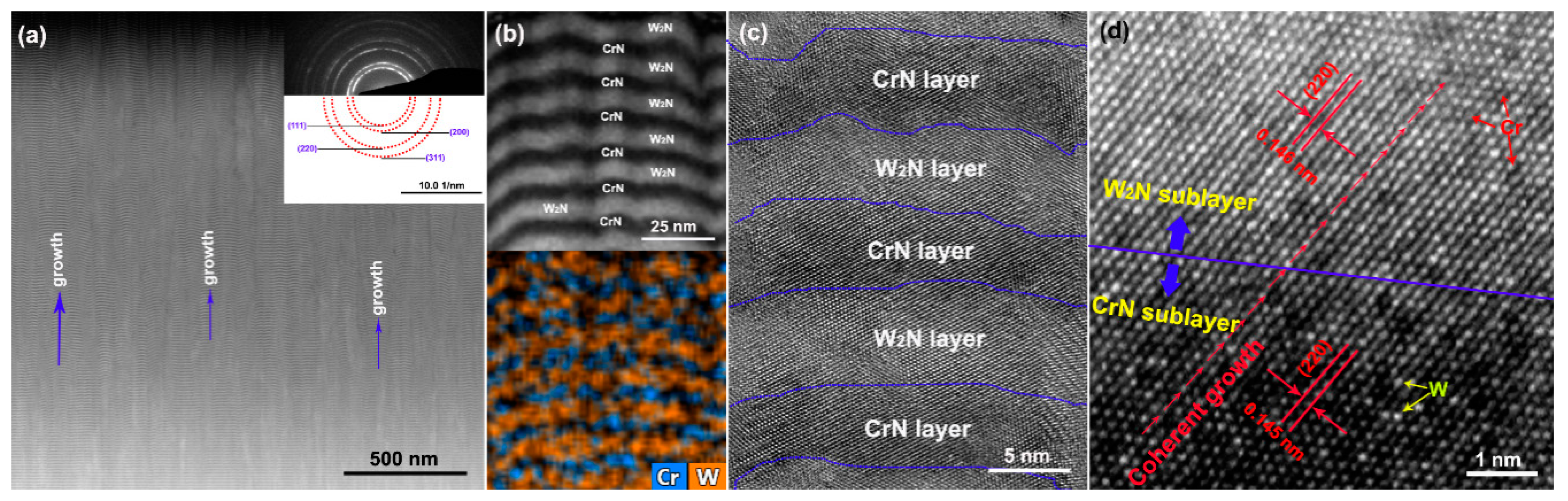
  • The as-deposited coatings showed columnar structures consisting of multilayer c-CrN and c-W2N phases. The preferential orientation of these structures varied from (111) to (200), and the surfaces became smoother under increasing W content.
  • The as-deposited coatings suffered from aggravated lattice expansion. The grain size and cluster particle sizes showed an obvious decrease under increasing W content. These changes led to a constant hardness enhancement.
  • The annealed coatings underwent minor oxidation and varying degrees of surface coarsening. The roughness value gradually increased due to an increasing volume fraction of W oxides.
  • The annealed coatings experienced spinodal decomposition while forming nm-sized c-CrN, c-W2N, and h-WN domains. The volume fraction of the h-WN phase increased significantly with the increase of W content.
The annealed coating under low W content exhibited a significant age-hardening due to the strain fields originating from the lattice mismatch. The annealed coating under high W content suffered from a severe hardness degradation because the large volume fraction of h-WN seriously weakened the interface strengthening effect.

Author Contributions

Conceptualization, Z.X. and F.G.; Methodology, Y.C.; Investigation, X.H. and K.L.; Supervision, Q.C. All authors have read and agreed to the published version of the manuscript.

Funding

This work was supported by National Natural Science Foundation of China (51771087), Liaoning Innovative Talents Support Plan (LR2017052), University of Science and Technology Liaoning Talent Project Grants (601011507-07), and the Innovation Team of Liaoning University of Science and Technology (2017TD04).

Acknowledgments

We sincerely thank the Institute of Nano Surface Engineering of Shenzhen University for their TEM technical supports.

Conflicts of Interest

The authors declare no conflict of interest.

References

  1. Zhang, S.; Zhou, L.; Xue, C.; Wang, L. Design and simulation of a superposition compound eye system based on hybrid diffractive-refractive lenses. J. Appl. Opt. 2017, 56, 7442–7449. [Google Scholar] [CrossRef] [PubMed]
  2. Jiang, C.; Lim, B.; Zhang, S. Three-dimensional shape measurement using a structured light system with dual projectors. Appl. Opt. 2018, 57, 3983–3990. [Google Scholar] [CrossRef] [PubMed]
  3. Yin, S.; Jia, H.; Zhang, G.; Chen, F.; Zhu, K. Review of small aspheric glass lens molding technologies. Front. Mech. Eng. 2017, 12, 66–76. [Google Scholar] [CrossRef]
  4. Tang, L.; Zhou, T.; Zhou, J.; Liang, Z.; Wang, X. Research on single point diamond turning of chalcogenide glass aspheric lens. Procedia CIRP 2018, 71, 293–298. [Google Scholar] [CrossRef]
  5. Tao, B.; He, P.; Shen, L.; Yi, A. Quantitatively measurement and analysis of residual stresses in molded aspherical glass lenses. Int. J. Adv. Manuf. Tech. 2014, 74, 1167–1174. [Google Scholar] [CrossRef]
  6. Firestone, G.C.; Yi, A.Y. Precision compression molding of glass microlenses and microlens arrays—An experimental study. Appl. Opt. 2005, 44, 6115–6122. [Google Scholar] [CrossRef]
  7. Yi, A.Y.; Chen, Y.; Klocke, F.; Pongs, G.; Demmer, A.; Grewell, D.; Benatar, A. A high volume precision compression molding process of glass diffractive optics by use of a micromachined fused silica wafer mold and low Tg optical glass. J. Micromech. Microeng. 2006, 16, 2000–2005. [Google Scholar] [CrossRef]
  8. Rieser, D.; Spieß, G.; Manns, P. Investigations on glass-to-mold sticking in the hot forming process. J. Non-Crystal. Solids 2008, 354, 1393–1397. [Google Scholar] [CrossRef]
  9. Fischbach, K.D.; Georgiadis, K.; Wang, F.; Dambon, O.; Klocke, F.; Chen, Y.; Allen, Y.Y. Investigation of the effects of process parameters on the glass-to-mold sticking force during precision glass molding. Surf. Coat. Technol. 2010, 205, 312–319. [Google Scholar] [CrossRef]
  10. Klocke, F.; Bouzakis, K.-D.; Georgiadis, K.; Gerardis, S.; Skordaris, G.; Pappa, M. Adhesive interlayers’ effect on the entire structure strength of glass molding tools’ Pt-Ir coatings by nano-tests determined. Surf. Coat. Technol. 2011, 206, 1867–1872. [Google Scholar] [CrossRef]
  11. Zhu, X.-Y.; Wei, J.-J.; Chen, L.-X.; Liu, J.-L.; Hei, L.-F.; Li, C.-M.; Zhang, Y. Anti-sticking Re-Ir coating for glass molding process. Thin Solid Films 2015, 584, 305–309. [Google Scholar] [CrossRef] [Green Version]
  12. Tseng, S.F.; Lee, C.T.; Huang, K.C.; Chiang, D.; Huang, C.Y.; Chou, C.P. Mechanical properties of Pt-Ir and Ni-Ir binary alloys for glass-molding dies coating. J. Nanosci. Nanotechnol. 2011, 11, 8682–8688. [Google Scholar] [CrossRef] [PubMed]
  13. Bernhardt, F.; Georgiadis, K.; Dolle, L.; Dambon, O.; Klocke, F. Development of a ta-C diamond-like carbon (DLC) coating by magnetron sputtering for use in precision glass molding. Materialwissenschaft und Werkstofftechnik 2013, 44, 661–666. [Google Scholar] [CrossRef]
  14. Xie, Z.W.; Wang, L.P.; Wang, X.F.; Huang, L.; Lu, Y.; Yan, J.C. Influence of high temperature annealing on the structure, hardness and tribological properties of diamond-like carbon and TiAlSiCN nanocomposite coatings. Appl. Surf. Sci. 2011, 258, 1206–1211. [Google Scholar] [CrossRef]
  15. Chen, Y.-I.; Lin, Y.-T.; Chang, L.-C.; Lee, J.-W. Preparation and annealing study of CrTaN coatings on WC-Co. Surf. Coat. Technol. 2011, 206, 1640–1647. [Google Scholar] [CrossRef]
  16. Chen, Y.-I.; Lin, K.-Y.; Wang, H.-H.; Cheng, Y.-R. Characterization of Ta-Si-N coatings prepared using direct current magnetron co-sputtering. Appl. Surf. Sci. 2014, 305, 805–816. [Google Scholar] [CrossRef]
  17. Chang, L.-C.; Chang, C.-Y.; Chen, Y.-I. Mechanical properties and oxidation resistance of reactively sputtered Ta1-xZrxNy thin films. Surf. Coat. Technol. 2015, 280, 27–36. [Google Scholar] [CrossRef]
  18. Chen, Y.-I.; Wang, H.-H. Oxidation resistance and mechanical properties of Cr-Ta-Si-N coatings in glass molding processes. Surf. Coat. Technol. 2014, 260, 118–125. [Google Scholar] [CrossRef]
  19. Lin, T.-N.; Han, S.; Weng, K.-W.; Lee, C.-T. Investigation on the structural and mechanical properties of anti-sticking sputtered tungsten chromium nitride films. Thin Solid Films 2013, 529, 333–337. [Google Scholar] [CrossRef]
  20. Chen, Y.-I.; Cheng, Y.-R.; Chang, L.-C.; Lee, J.-W. Chemical inertness of Cr-W-N coatings in glass molding. Thin Solid Films 2015, 593, 102–109. [Google Scholar] [CrossRef]
  21. Zhang, X.; Zhou, Y.-W.; Gao, J.-B.; Zhao, Z.-W.; Guo, Y.-Y.; Xie, Z.-W.; Kelly, P. Effect of the filament discharge current on the microstructure and performance of plasma-enhanced magnetron sputtered TiN coatings. J. Alloys Compd. 2017, 725, 877–883. [Google Scholar] [CrossRef] [Green Version]
  22. Gu, B.; Tu, J.P.; Zheng, X.H.; Yang, Y.Z.; Penga, S.M. Comparison in mechanical and tribological properties of Cr-W-N and Cr-Mo-N multilayer films deposited by DC reactive magnetron sputtering. Surf. Coat. Technol. 2008, 202, 2189–2193. [Google Scholar] [CrossRef]
  23. Lin, C.-H.; Duh, J.-G.; Yau, B.-S. Processing of chromium tungsten nitride hard coatings for glass molding. Surf. Coat. Technol. 2006, 201, 1316–1322. [Google Scholar] [CrossRef]
  24. Hones, P.; Sanjinés, R.; Lévy, F. Sputter deposited chromium nitride based ternary compounds for hard coatings. Thin Solid Films 1998, 332, 240–246. [Google Scholar] [CrossRef]
  25. Wu, Z.; Tian, X.; Gong, C.; Yang, S.; Chu, P.K. Micrograph and structure of CrN films prepared by plasma immersion ion implantation and deposition using HPPMS plasma source. Surf. Coat. Technol. 2013, 229, 210–216. [Google Scholar] [CrossRef]
  26. Lippitz, A.; Hübert, T.H. XPS investigations of chromium nitride thin films. Surf. Coat. Technol. 2005, 200, 250–253. [Google Scholar] [CrossRef]
  27. Chang, J.H.; Jung, M.N.; Park, J.S.; Park, S.H.; Im, I.H.; Lee, H.J.; Ha, J.S.; Fujii, K.; Hanada, T.; Yao, T.; et al. X-ray photoelectron spectroscopy study on the CrN surface grown on sapphire substrate to control the polarity of ZnO by plasma-assisted molecular beam epitaxy. Appl. Surf. Sci. 2009, 255, 8582–8586. [Google Scholar] [CrossRef]
  28. Zhang, X.X.; Wu, Y.Z.; Mu, B.; Qiao, L.; Li, W.X.; Li, J.J.; Wang, P. Thermal stability of tungsten sub-nitride thin film prepared by reactive magnetron sputtering. J. Nucl. Mater. 2017, 485, 1–7. [Google Scholar] [CrossRef]
  29. Baker, C.C.; Shah, S.I. Reactive sputter deposition of tungsten nitride thin films. J. Vac. Sci. Technol. A 2002, 20, 1699–1703. [Google Scholar] [CrossRef]
  30. Wang, Z.; Liu, Z.; Yang, Z.; Shingubara, S. Characterization of sputtered tungsten nitride flm and its application to Cu electroless plating. Microelectr. Eng. 2008, 85, 395–400. [Google Scholar] [CrossRef]
  31. Agouram, S.; Bodart, F.; Terwagne, G. LEEIXS and XPS studies of reactive unbalanced magnetron sputtered chromium oxynitride thin films with air. J. Electron Spectrosc. Relat. Phenom. 2004, 134, 173–181. [Google Scholar] [CrossRef]
  32. Song, H.Y.; Jiang, H.F.; Liu, X.Q.; Jiang, Y.Z.; Meng, G.Y. Preparation of WOx-TiO2 and the Photocatalytic Activity under Visible Irradiation. Key. Eng. Mater. 2007, 336–338, 1979–1982. [Google Scholar] [CrossRef]
  33. Lu, F.H.; Chen, H.Y.; Hung, C.H. Degradation of CrN films at high temperature under controlled atmosphere. JVSTA 2003, 21, 671. [Google Scholar] [CrossRef]
  34. Asgary, S.; Hantehzadeh, M.R.; Ghoranneviss, M. Temperature dependence of copper diffusion in different thickness amorphous tungsten/tungsten nitride layer. Phys. Met. Metall. 2017, 118, 1127–1135. [Google Scholar] [CrossRef]
  35. Chang, Y.Y.; Hsiao, C.Y. High temperature oxidation resistance of multicomponent Cr-Ti-Al-Si-N coatings. Surf. Coat. Technol. 2009, 204, 992–996. [Google Scholar] [CrossRef]
  36. Zou, H.K.; Chen, L.; Chang, K.K.; Pei, F.; Du, Y. Enhanced hardness and age-hardening of TiAlN coatings through Ru-addition. Scr. Mater. 2019, 162, 382–386. [Google Scholar] [CrossRef]
  37. Ha, C.; Xu, Y.X.; Chen, L.; Pei, F.; Du, Y. Mechanical properties, thermal stability and oxidation resistance of Ta-doped CrAlN coatings. Surf. Coat. Technol. 2019, 368, 25–32. [Google Scholar]
  38. Chen, L.; Du, Y.; Mayrhofer, P.H.; Wang, S.Q.; Li, J. The influence of age-hardening on turning and milling performance of Ti-Al-N coated inserts. Surf. Coat. Technol. 2008, 202, 5158–5161. [Google Scholar] [CrossRef]
  39. Mayrhofer, P.H.; Hörling, A.; Karlsson, L.; Sjoelen, J. Self-organized nanostructures in the Ti-Al-N system. Appl. Phys. Lett. 2003, 83, 2049–2051. [Google Scholar] [CrossRef]
Figure 1. XRD patterns of as-deposited coatings.
Coatings 10 00198 g001
Figure 2. XPS spectra of sample C2: (a) Cr2p, (b) W4f, (c) N1s, (d) O1s.
Coatings 10 00198 g002
Figure 3. Surface SEM images of as-deposited coatings: (a) C1, (b) C2, (c) C3.
Coatings 10 00198 g003
Figure 4. Cross-section TEM images of sample C2: (a) TEM image with corresponding SADP, (b) HAADF STEM image and element mapping, (c,d) HRTEM images.
Coatings 10 00198 g004
Figure 5. AFM images of as-deposited coatings: (a) C1, (b) C2, (c) C3.
Coatings 10 00198 g005
Figure 6. XRD patterns of vacuum annealed coatings.
Coatings 10 00198 g006
Figure 7. XRD patterns and cross-section TEM images of as-deposited (a) and annealed (b) sample C2.
Coatings 10 00198 g007
Figure 8. Surface images and EDS spectra of vacuum annealed coatings: (a) C1, (b) C2, (c) C3.
Coatings 10 00198 g008
Figure 9. Roughness values and AFM images of as-deposited and annealed coatings: C1, C2, C3.
Coatings 10 00198 g009
Figure 10. Hardness of as-deposited and annealed coatings.
Coatings 10 00198 g010
Table 1. Experimental details of as-deposited coatings.
SamplesPower of Cr Target (W)Power of W Target (W)Time (min)
C15000400065
C227004000100
C316005100100
Table 2. Chemical compositions of as-deposited coatings.
SampleCr at %W at %N at %O at %
C135.9 ± 2.321.8 ± 5.040.2 ± 4.82.1 ± 0.6
C226.4 ± 1.431.9 ± 6.140.3 ± 4.51.4 ± 0.5
C313.9 ± 0.742.1 ± 6.943.1 ± 4.40.9 ± 0.4

