Article

A Tunable Beamforming Ferroelectric Lens for Millimeter Wavelength Ranges

by
Roman Platonov
*,†,
Andrey Altynnikov
and
Andrey Kozyrev
Department of Physical Electronics and Technology, St. Petersburg Electrotechnical University (“LETI”), Prof. Popova St. 5, 197376 St. Petersburg, Russia
*
Author to whom correspondence should be addressed.
These authors contributed equally to this work.
Coatings 2020, 10(2), 180; https://doi.org/10.3390/coatings10020180
Submission received: 21 January 2020 / Revised: 11 February 2020 / Accepted: 13 February 2020 / Published: 16 February 2020
(This article belongs to the Special Issue Ferroelectric Thin Films and Devices)

Abstract

:
The advanced design of a millimeter-wave quasi-optical beamforming device (QOBD) based on the ferroelectric ceramic was elaborated and considered. Among the advantages of the proposed design are simplicity and cost-effectiveness in contrast to conventional analog and digital beamforming devices based on array antennas. The use of ferroelectric ceramic in the QOBD design allows operating in a wide frequency range up to 100 GHz. The advanced topology of discrete radiotransparent electrodes to provide a realization of different beamforming functions such as beam focusing and beam scanning was considered. The prototype of the proposed QOBD was designed to operate at 60 GHz. The measured radiation pattern of the QOBD prototype is in good agreement with the simulated one. Measurements demonstrate decreasing of beamwidth of the primary antenna radiation pattern by the lens prototype operating in the beam focusing regime.

1. Introduction

From the beginning of the wireless communication development, there has been an increase in the transferred information and operating frequencies. Today, researchers and developers face new challenges: to make compact devices with reasonable power consumption and outstanding wireless data transfer capabilities. Such devices should become a base for innovative infrastructures such as the 5G network [1], WiGig network [2], “smart home”, and its probable extension to the “smart city” [3]. To overcome these challenges, one looks for a further increase of the operating frequency and migration to the millimeter wavelengths range [4]. However, the millimeter wavelength range demonstrates a significant attenuation of electromagnetic waves in free space [5]; thus, the antennas with high directivity are of interest.
The lens antennas become more attractive for applications in the millimeter wave range because of a good trade-off between directivity and the degree of insertion loss [6,7,8]. However, as a rule, one should implement a mechanical system to provide a continuous beam steering capability [9]. Another way is to use several feed antennas to provide discrete switching of the beam position [10]. Both approaches lead to an increase in the system’s complexity as well as cost. These disadvantages limit the range of possible applications of lens antennas.
The principles of lens antenna design are the origins of designing so-called “quasi-optical” beamforming devices (QOBD) in micro- and millimeter-wave bands. There are a lot of different QOBD constructions with various beamforming functions such as focus lenses [10], deflectors [11], polarization controllers [12], etc. The realization of tunable QOBD beamforming functions relies on the use of nonlinear elements such as PIN diodes [13], semiconductor or ferroelectric (FE) varactors [14], and microelectromechanical systems (MEMS) [15]. The class of nonlinear elements determines time response, insertion loss, and the type of beamforming (a continuous or discrete one). Such nonlinear elements operate as lumped ones; it means that the size of an element is much smaller than an operational wavelength ( L λ 0 ). As a rule, the operating frequencies of most proposed QOBDs are limited up to frequencies of Ka-band. To overcome this limitation, one should base QOBD design on nonlinear distributed elements (i.e., at a condition of L λ 0 ). The ferroelectrics (in particular, a solid solution of the BaxSrx−1TiO3 (BSTO)) demonstrate a fast time response, low dissipation loss, and the absence of permittivity dispersion in a wide frequency range (up to 100 GHz) in the paraelectric state [16,17,18,19]. These features allow considering BSTO as a promising material for the millimeter-wave QOBD on the base of nonlinear distributed elements.
This article is devoted to the design of the electrically tunable ferroelectric QOBD for the millimeter wavelength range. The simple and effective model of the device, allowing to design QOBD with different beamforming functions, was proposed. The effectiveness of the model was confirmed by simulation and experimental results. Note that the results of the experimental investigation of FE ceramic materials were used during the simulation. The influence of the elaborated topology of discrete control electrodes on QOBD performance was considered. In accordance with simulation results, it was shown that the proposed lens design allows combining different beamforming functions (or operation regimes) such as beam focusing and beam scanning. The prototype of the proposed lens was fabricated and experimentally tested at 60 GHz. The results of measurements of the lens radiation pattern are in a good agreement with simulated ones.

2. Materials and Methods

2.1. Principle of Ferroelectric Lens Operation

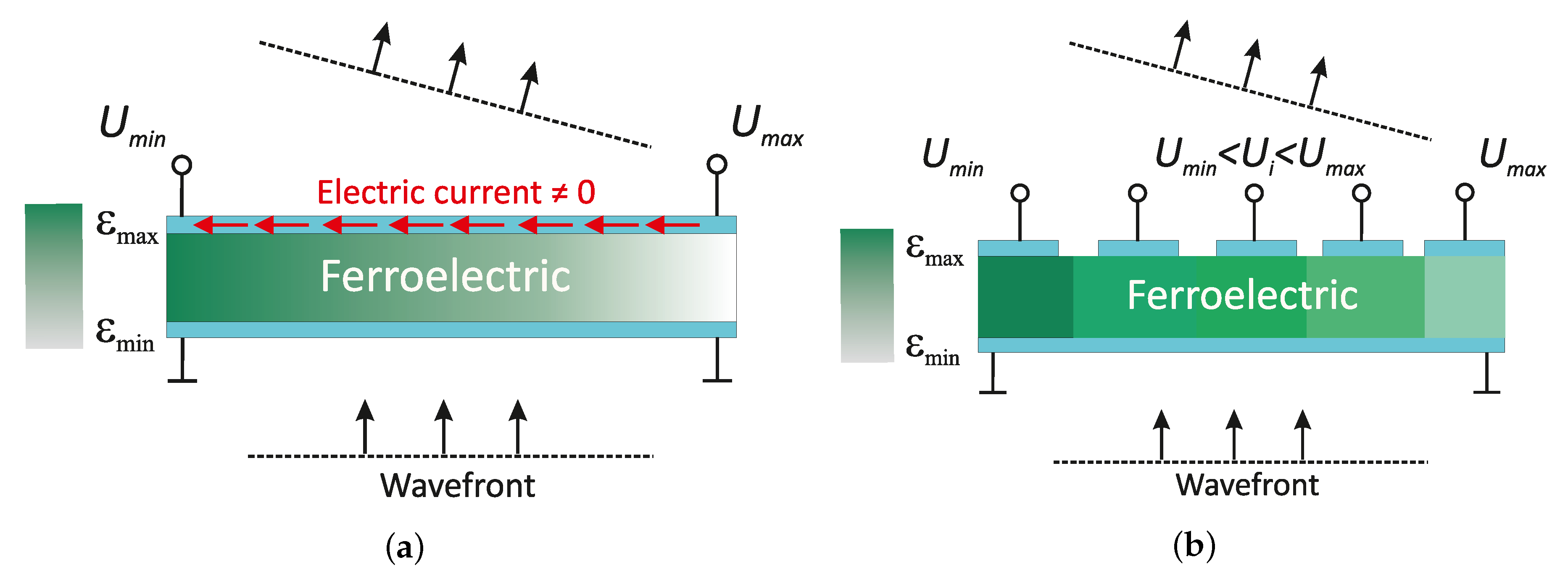
A traditional lens antenna is based on the use of linear dielectric lenses with a feed antenna. In this case, the curvature of a lens profile (variation of lens thickness) determines a radiation pattern as schematically shown in Figure 1a. As a rule, the permittivity constant of linear material is not more than ∼20, so it is difficult to design a compact dielectric lens. The ferroelectrics have a dependency of permittivity ( ε F E ) on the applied electric field (E); thereby, the curvature of the lens can be formed by the permittivity variation along FE plate by electric field application. The QOBD based on ferroelectric plate is presented in Figure 1b. Let’s assume the electromagnetic wave propagates through the FE plate with the thickness of d F E , then FE element’s equivalent electrical thickness (EET) measured in degrees can be defined as:
EET = 2 π ε F E ( E ) λ 0 d F E
where λ 0 is the wavelength at the operating a frequency of the FE lens in free space. The use of ferroelectrics allows providing the electrical control over a spatial distribution of the EET and, thus, control over the forming radiation pattern (as schematically shown in Figure 1b). It leads to a realization of different electrical beamforming regimes by a single lens, such as beam focusing and beam scanning.
The main characteristic of ferroelectric material nonlinearity is the tunability factor K, that can be defined as:
K = ε F E 0 ε F E E 0
Therefore with the use of (1) and (2) the FE lens EET variation in dependency on the electric field becomes:
Δ EET K = EET 1 EET K 1 = 2 π d F E ε F E λ 0 1 1 K
One should take into account the insertion loss caused by FE dissipation loss ( t a n δ ) during the design process. It can be done directly during numerical simulation or by the use of equivalent electrical representation of FE ceramic plates, as was shown in [20].
To realize the control over FE permittivity, one should provide control electrodes in the lens design. The control electrodes should correspond to several requirements, such as low insertion loss, simple implementation, and minimizing the heating of the FE plate caused by the electric current (Joule heating).

2.2. Topology of the Control Electrodes

In the first works devoted to FE lens design, metal electrodes were used [21,22,23]. However, it leads to an increase of design complexity due to the decomposition of the lens aperture into an array of separate FE elements with deposited metal electrodes. It is much more convenient to use radiotransparent electrodes based on a thin film of the high resistive materials. The well-known high resistive materials used for optically transparent electrodes such as ZnO [24] demonstrates low insertion loss values in the RF/MW range. Thereby, such materials can be considered for the realization of control electrodes of the FE lens.
In works [25,26], radiotransparent electrodes were presented as two continuous thin films deposited on both sides of the FE ceramic plate as schematically shown in Figure 2a. One thin film is the control electrode and is connected to the voltage sources while the other is a grounded electrode. The operation voltage continuously drops along the control electrode from U m a x to U m i n . Thus, the electric field formed in the FE plate leads to permittivity variation and, consequently, to the spatial distribution of EET along the FE plate.
Despite the simplicity of the continuous electrode configuration, it has drawbacks. The first one is the electric current flowing through the control electrode thin film induced by the voltage difference applied at opposite electrode edges. This may lead to radiation pattern instability caused by Joule heating of the FE plate. Secondly, the continuous control electrode limits the functional capabilities of the FE lens to only beam scanning [26] or beam focusing [25].
In this work, the discrete topology of the control electrode is proposed. It consists of the discrete sections of a radiotransparent material as presented in Figure 2b. The electric potential applies to each section of the electrode. In such a configuration, each electrode section is an open-circuit for the control voltage and, therefore, the electric current is not flowing through it. Besides, this topology allows the application of voltage to each electrode section separately and to form different spatial distributions of FE permittivity, i.e., realize different beamforming functions.
The proposed electrode topology allows realizing the discrete spatial distributions of EET with a discretization period corresponded to the width of the electrode section, as presented in Figure 2b. The angular spectrum method [27,28] may be used to analyze the influence of electrode section width on the quality of a radiation pattern. This method is based on an expansion of a wave field into a sum of a large number of plane waves. The far-field angular distribution ( E f ) is the Fourier transform of the complex E-field values of the wave in the aperture plane ( E a ):
E f k x = E a x e j k x x d x ,
where k x is a projection of the wave vector on the x-axis, which is directed along the aperture plane.
In a discrete form the expression (4) become:
E d f k x = 0 N 1 E a Δ x n e j k x Δ x n ,
where N – total number of spatial discrete intervals, n – index of summation, Δ x – spatial discrete interval in fraction of wavelength, i.e.,:
Δ x = x n x n 1 = λ 0 m
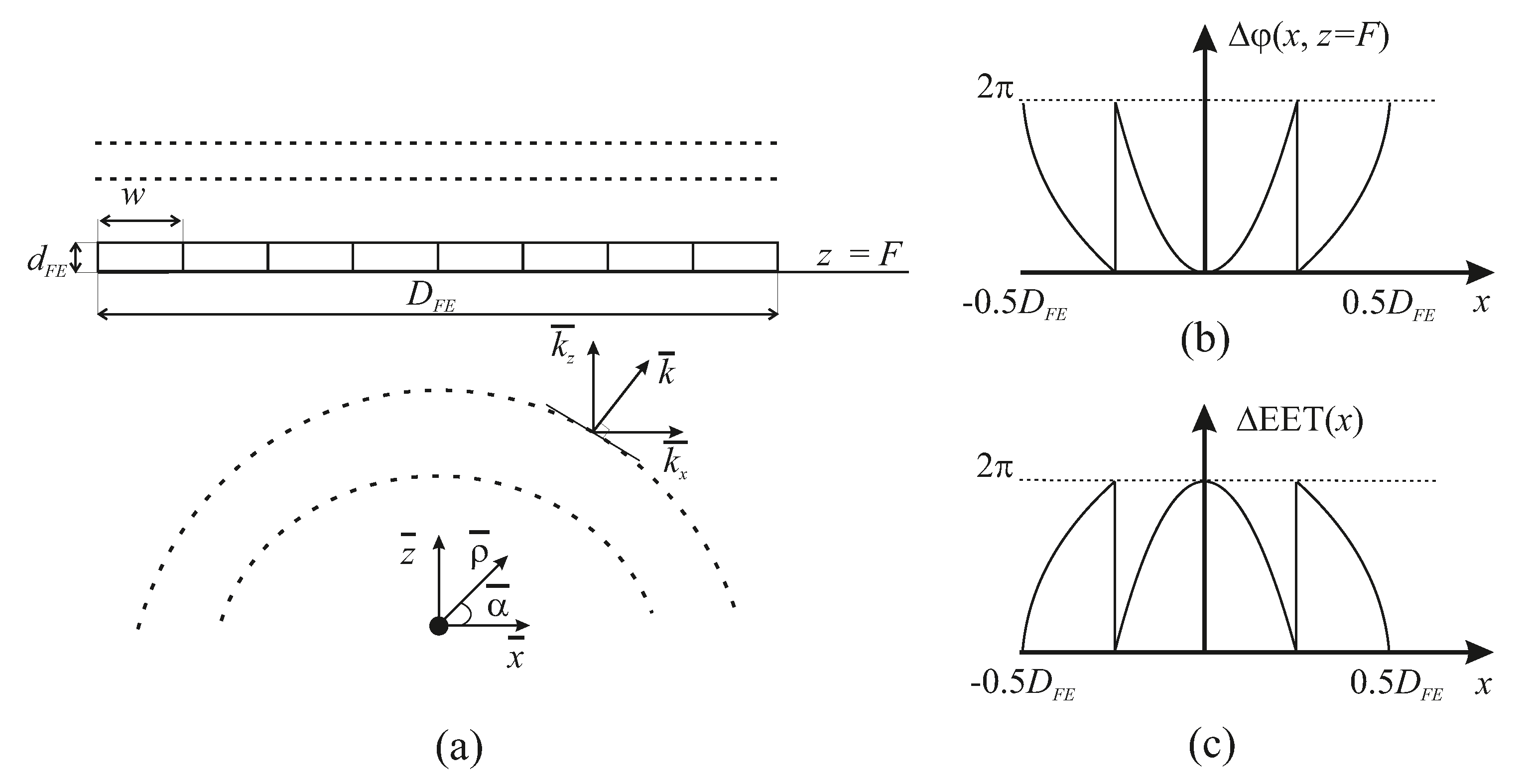
where m is an auxiliary variable, which is used to define the spatial discrete interval as a fraction of wavelength. Obviously that the values of the exponent order in the Equation (5) is limited to the range [− π ; π ]. The use of a 2D approximation assumption allows defining k x as a projection of the wavevector k on the x-axis, i.e., k x = k sin α , where α is an azimuth angle in cylindrical coordinates (see Figure 3a). Thus with use of (6) one can conclude that:
k sin α λ 0 m π
and that m 2 in condition of normal incidence of wave to the aperture plane (i.e., sin α = 1 ). For simplicity, it is assumed that the spatial discrete interval of the lens aperture is equal to the width of the radiotransparent electrode section (w), thus (7) leads to
w λ 0 2 .
In the case of w more than half of a wavelength, it is supposed to appearing of grating lobes and degradation of a radiation pattern.

2.3. Ferroelectric Lens Model

To clarify the FE lens design procedure, let us consider the 2D model of the lens with feed antenna schematically presented in Figure 3a. For simplicity, we will assume that the feed antenna is a point source with isotropic radiation pattern and FE lens placed at the distance F. In Figure 3b we schematically present the distribution of the wave phase ( Δ ϕ = ϕ 0 ϕ x ) along aperture of the FE lens ( D F E ). The FE lens should compensate for the phase difference obtained with distance by the appropriate spatial distribution of the EET (as schematically shown in Figure 3c) in order to form radiation pattern with a focused beam. The presented simplified case allows calculating the phase with the help of a solution of the Helmholtz equation:
z 2 + k z 2 g z = δ z ,
where z 2 —differential operator of second degree defined along z-axis; k z – projection of the wave vector k on the direction of the wave propagation (z-axis); g z —Green’s function; δ z —Dirac delta function, described point source of the radiation.
The use of the trigonometric expressions allows writing k z in polar coordinates, as follows:
k z = k cos α
k x = k sin α
k z = k 2 k x 2 = k 1 sin 2 α = k cos α = 2 π λ 0 cos α
Since the solution of Equation (9) is well-known with the help of expressions (10)–(12) it is possible to obtain required ΔEET angular distribution via Green’s function:
g α , | z | = e j | z | 2 π λ 0 cos α j 4 π λ 0 cos α .
Obviously, g ( α , | z | ) in (13) is a complex value, and thus, its argument determines the phase of the wave propagated to the distance | z | in a direction defined by α . Hence the required ΔEET distribution may be found by inversion of the obtained phase distribution sign:
Δ EET α , | z | = arg e j arg [ g ( α , | z | ) ]
Results of the calculation on the base of (14) allow defining the required spatial distribution of EET along the lens aperture to provide the beam focusing (see Figure 3c). A more detailed beam scanning regime is described in Section 3.1. In accordance with the Equation (3), one can obtain the spatial distribution of tunability factor for the FE lens from calculated EET distribution. The use of K-factor spatial distribution is more convenient during the design process rather than control voltage values ( U c ) because U c for defined K is dependent on the thickness and composition of FE material. The described model may be adapted to use different feed antennas. It can be based on computer-aided optimization methods. In this case, the K-factor distribution obtained in the assumption of an isotropic source may be used as the origin state of the optimization procedure.

2.4. Materials

As was noted in previous sections, a ferroelectric ceramic plate is a key element of the proposed QOBD construction. The ceramic plates were made from a mixture of previously synthesized BaTiO3 and SrTiO3 powders with proportions 55/45 to perform an experimental investigation of FE characteristics. The initial mixture was doped by the linear dielectric additives (Mg2TiO4, MgO) to decrease permittivity value down to ε F E = 440 and dielectric loss.
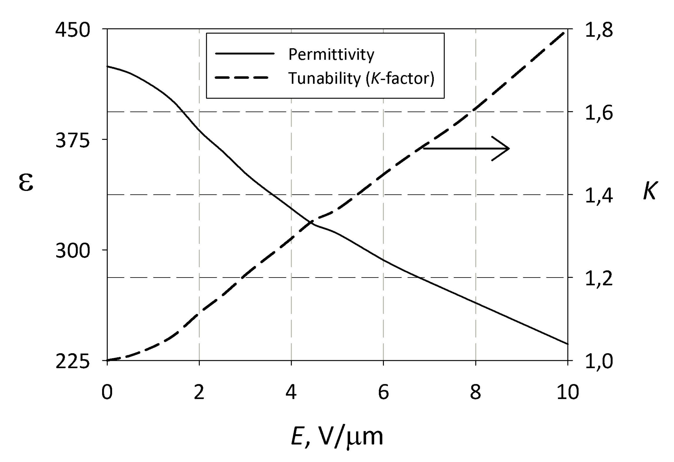
The characterization of FE nonlinearity is provided by capacitance-voltage C V dependency measurements of FE capacitors under dc control voltages resulting in a tunability factor K = C ( 0 ) / C ( U d c ) . The FE ceramic capacitors were fabricated with 5 × 5 mm2 contact copper metallization deposited on the opposite sides of ceramic plate. For the measurement procedure, the RLC-meter (GW Instek LCR-8101G) with the operating frequency of 1 MHz was used. Due to the absence of frequency dispersion of FE permittivity up to 100 GHz, the experimental results obtained at 1 MHz are valid in millimeter-waves range. Obtained experimental results of tunability and permittivity dependencies on the electric field are presented in Figure 4.
To provide high precision measurements of ceramic t a n δ the electrodeless method based on an open resonator (OR) was used. The OR is intended to be used in the frequency range of f = (40–75) GHz. The unloaded quality factor of the empty OR is of Q (60 GHz) = (5–6)·104. Theoretical approach of measurements is based on results of the theory developed by [29] for E- and H-field distribution in an OR with a single-layer dielectric. The dielectric loss values of the ferroelectric ceramic samples with size 48 × 60 × 1 mm3 were measured via the OR at frequency ∼60 GHz. Note that the sizes of measured samples were significantly more than operating wavelength; this allows to avoid the small-sized body influence on the quality factor of the OR described in [30]. In accordance with the described measure technique, the loss tangent value of the ferroelectric ceramic plate was about 0.015–0.02 at 60 GHz.
Graphite was used to form the electrode topology in the proposed prototype design to simplify manufacturing. The graphite films with thickness ∼10 μm demonstrate the surface resistance of 1–2 kOhm/sq and insertion loss of about 2 dB per graphite layer at f = 60 GHz. It should be emphasized, that graphite used only for prototype manufacturing and is not considering as perspective material for radiotransparent electrodes. The insertion loss per electrode layer can be decreased down to ∼0.4 dB in the case of the use of ZnO material. This value was calculated on the base of the ZnO resistivity (∼108 Ohm cm) provided in [31].
The prototype of the FE lens was manufactured for experimental confirmation of simulated results. Two FE plates with dimensions of 48 × 60 × 1 mm3 were used in the prototype design. Utilization of two identical FE plates allows decreasing the magnitude of the control voltage applied to each plate. The holder of the FE plates providing voltage application to the control electrodes was manufactured from ABS plastic by 3D-printing. The plates of linear ceramic were used as quarter-wave impedance matching layers in the lens prototype (see Figure 5).

3. Results and Discussion

3.1. Results of Simulation

The Radio Frequency module (Electromagnetic Waves, Frequency Domain interface) of the COMSOL Multiphysics software was used to perform the electromagnetic simulation of the FE lens to prove the proposed beamforming concept. The region of numerical simulation is presented as an air-filled circle of a radius of 25 wavelengths at 60 GHz with radiation boundaries containing a waveguide flaring to a horn and a ferroelectric lens with impedance matching layers. The width of the waveguide is 7 mm, and the length is 15 mm. The horn dimensions were calculated based on the procedure described in [32]. The length of the horn is 46 mm, and its aperture width is 32 mm. The size of mesh elements was specified to not exceed λ / 6 value, where λ is the wavelength in corresponded material. The lens model consists of ferroelectric plates with quarter wavelength matching layers of linear dielectric. The overall size of the FE lens aperture is 10 λ 0 (at 60 GHz) with a total thickness of the FE plates 2 mm. The FE plates were divided into 20 rectangular regions in accordance with (8) to provide the discrete spatial EET distribution. The permittivity of each region is determined as ε F E / K i , where ε F E – ferroelectric permittivity without control electric field ( ε F E = 440 ) and K i – tunability factor corresponded to the i-th FE region. At the first step, spatial distribution of the K-factor (see Figure 6a) was obtained in the assumption of a point isotropic source as was described above. The calculation was performed in the condition that focal distance F is about 21 λ 0 (∼10 cm).
The K-factor distribution was optimized during the simulation with the criteria of a better directivity and level of side lobes to provide the proper operation of the FE lens with the horn antenna. Distributions of the K-factor before and after optimization may be compared in Figure 6a,b, correspondingly. It should be noted that the focal distance is assumed as the distance between lens and plane where the waveguide starts to flare.
Besides beam focusing, the lens provides the possibility of beam scanning. In contrast to existed ferroelectric lens designs [11,23,25,26,33], the possibility to operate in several regimes can be considered as a significant advantage of the proposed lens. In the case of the use of feed antenna with high directivity, the ΔEET distribution providing deflection of the wavefront (i.e., beam scan regime) is a simple linear gradient. The height of the ΔEET gradient determines the angle of deflection. If it is necessary to provide a regime of focused beam scanning; one should combine ΔEET distributions for a focused beam with a linear gradient. Figure 6c presents an example of K-distribution corresponding to such a combined regime. The achievability of the obtained K-values for both regimes can be confirmed by the experimental dependence of the tunability on the electric field strength shown in Figure 4.
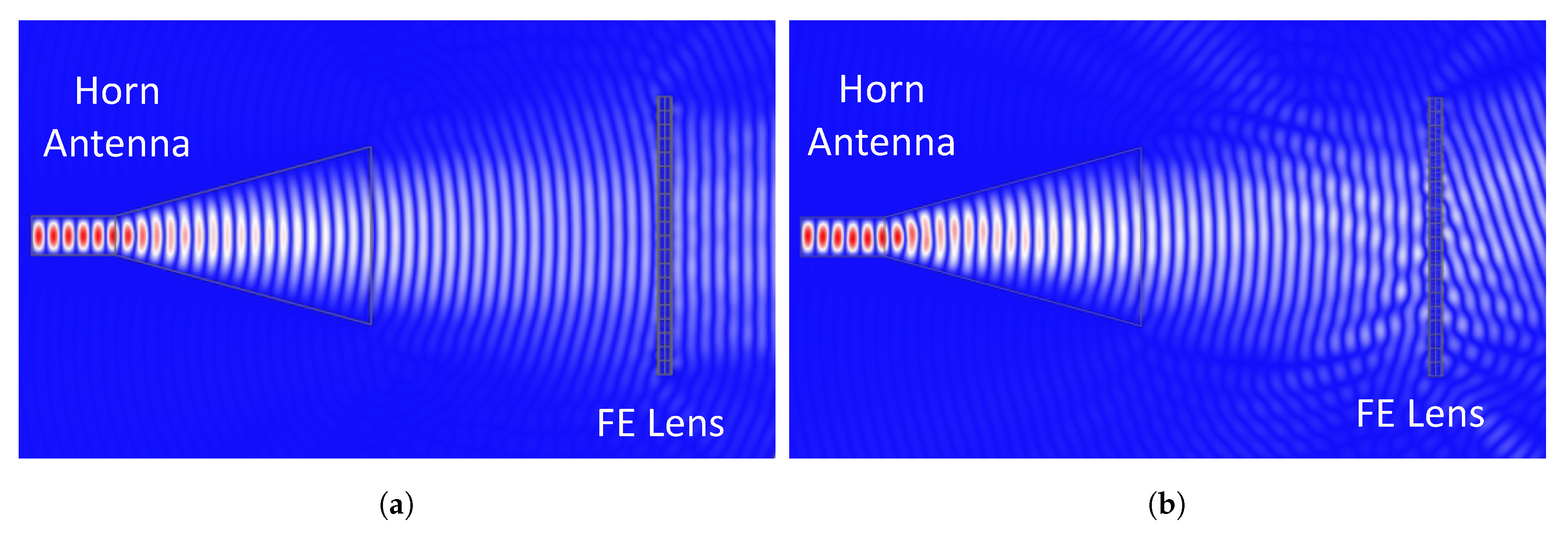
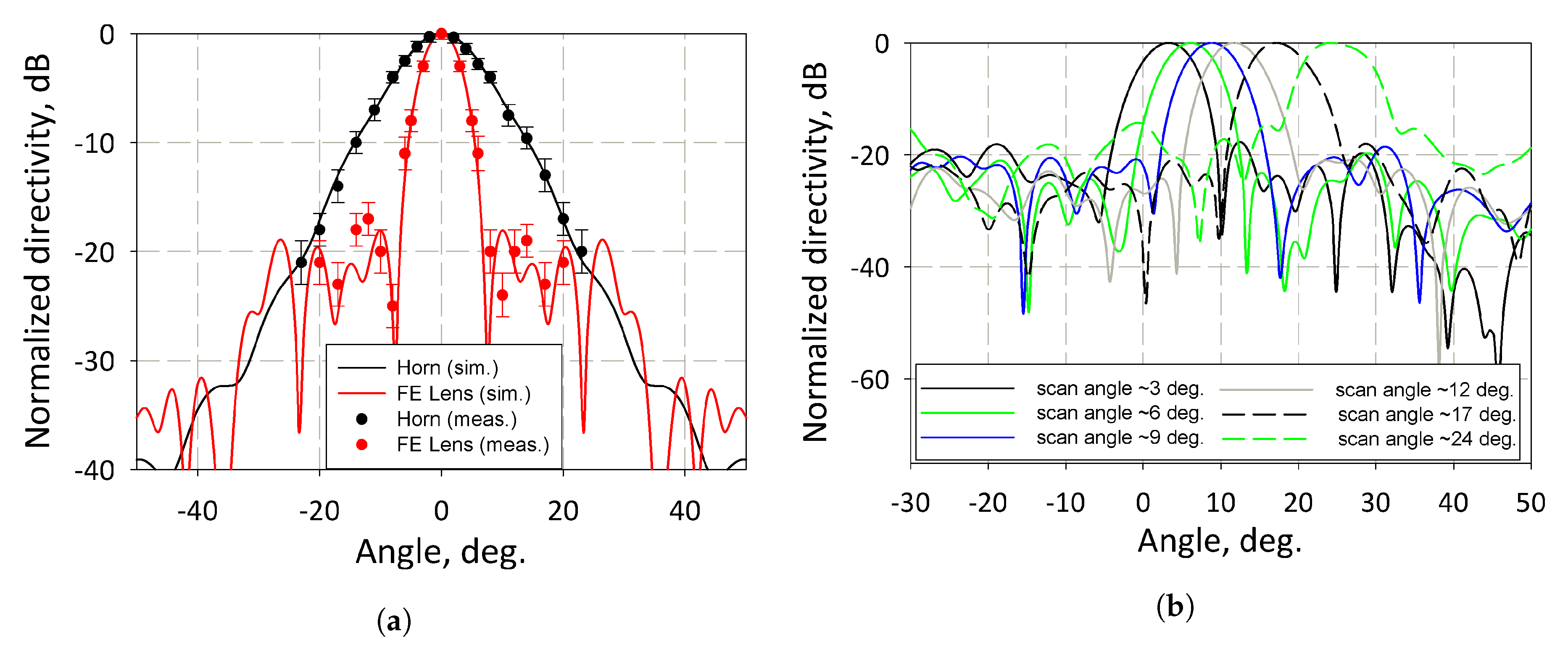
The simulation results of the wave E-field distribution corresponded to regimes of beam focusing and focused beam scanning are presented in Figure 7a,b correspondingly. The presented E-field distributions clearly demonstrate the required wavefront transformation for both cases. The effectiveness of the proposed lens can be concluded from the simulation results of radiation patterns presented in Figure 8. It demonstrates that the beamwidth of the feed antenna was reduced from 14 down to 7 deg, while the achievable scan angle value is 23 deg.
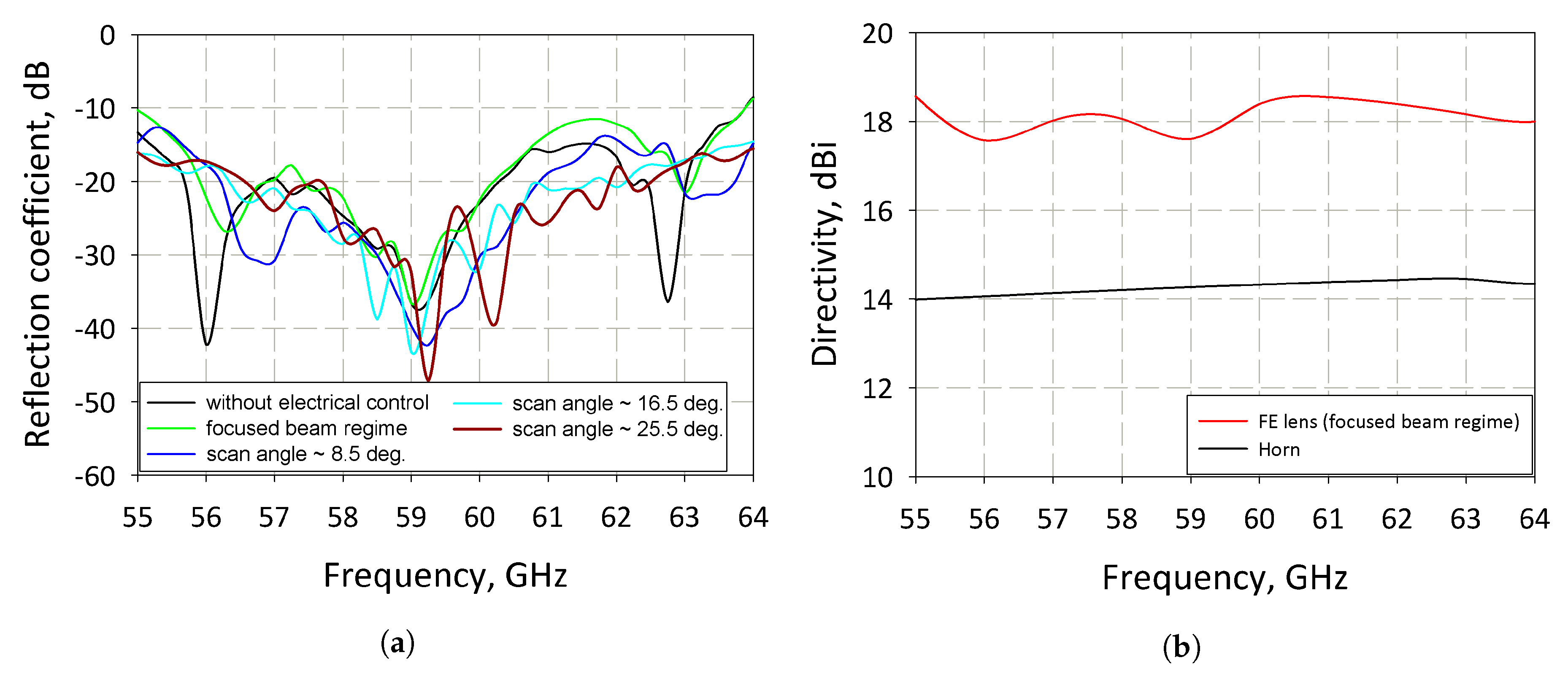
The reflection coefficient was calculated in a wide frequency range to estimate the impedance matching of the ferroelectric lens with free space via a single quarter-wave plate of a linear dielectric. Obviously, a variation of the FE permittivity along the lens aperture effects on impedance matching condition. Therefore, the simulation was performed for several cases: the FE lens without variation of the permittivity (i.e., ε F E = 440 for every part of the lens); the K-factor distribution corresponded to the beam focusing (as shown in Figure 6b); the K-factor distributions corresponded to the scanning of the focused beam (example of such distribution presented in Figure 6c). The simulation results are presented in Figure 9a. One can conclude that the reflection coefficient is less than −10 dB in a frequency band close to 9 GHz for all of the mentioned regimes of the lens operation. The directivity of the FE lens and the horn was simulated in the same frequency range (55–64 GHz) and presented in Figure 9b. The results demonstrate that ripples of the directivity do not exceed 3 dB in the considered frequency range. According to the obtained results, the lens design demonstrates a wide operating frequency band (∼9 GHz) comparable with the bulk dielectric lens [6,10].

3.2. Results of Measurements

The conical horns with an aperture diameter of 30 mm were used as feed and detector antennas during measurements of radiation patterns at 60 GHz. The special electrodes topology was formed on the ferroelectric plates’ surfaces to apply control voltage. The advantages of this topology were described in Section 2.2; the main one is the elimination of heating due to the absence of electric current in contrast to topologies used in existing lens designs [25,26]. It allows increasing the stability of the ferroelectric lens parameters during operation under a controlled voltage. To minimize the grating lobes of a radiation pattern, the sizes of electrode strips satisfy the condition (8). The maximum operating voltage (at the edge of the lens aperture) for the case of a beam focusing regime was approximately 2.1 kV. The high value of operating voltages can be significantly reduced by the use of a multilayer structure composed of thinner ceramic plates (in the order of 50–100 μm) in the case of an optimized manufacturing process of the FE lens. Figure 8 presents the measurement results of the beam focusing by the FE lens under control voltages corresponded to the distribution of K-factor from Figure 6b. The total insertion loss of the manufactured prototype at 60 GHz is ∼11 dB. Note that a significant part of the insertion loss value is due to the use of graphite electrodes. One can conclude that the manufactured FE lens prototype significantly decreases the main beam width of the horn radiation pattern (from 13 to 6 degrees at 3 dB level). As can be seen from the radiation pattern (see Figure 8a), several minor lobes appear around the level of −20 dB. Its properties can be explained by the effect of diffraction on the lens edges and spillover of the wave, which can be clearly observed in Figure 6.

4. Conclusions

The design of a quasi-optical beamforming device based on ferroelectric ceramic was considered and analyzed. The topology of electrodes to provide a realization of different beamforming functions was investigated. The absence of discrete elements in the lens design allows to simplify lens construction and provide operation in the millimeter wavelength range. The significant advantage of the proposed lens in contrast to existing ferroelectric lens designs is the possibility to operate in several regimes such as beam focusing and scanning of a focused beam. The possibility to adapt the FE lens performance in combination with different primary antennas based on an approximate model was demonstrated. The results of the simulation were confirmed by the measurements of the prototype radiation pattern at the operation frequency 60 GHz. Under the distribution of operation voltages calculated from the described model, the lens prototype demonstrates a significant decrease in the beam width in comparison with the feed horn antenna. Implementation of the proposed lens design in wireless communication or radar systems operating in the millimeter wavelength range is promising due to effectiveness and simplicity.

Author Contributions

Conceptualization, simulation, writing—original draft preparation, R.P.; conceptualization, measurements, writing—review and editing, A.A.; methodology, writing—review and editing, A.K. All authors have read and agreed to the published version of the manuscript.

Funding

This work is supported by the Russian Science Foundation under grant 18-79-10156.

Acknowledgments

The authors gratefully acknowledge the financial support provided by the Russian Science Foundation under grant 18-79-10156.

Conflicts of Interest

The authors declare no conflict of interest.

References

  1. Boccardi, F.; Heath, R.W.; Lozano, A.; Marzetta, T.L.; Popovski, P. Five disruptive technology directions for 5G. IEEE Commun. Mag. 2014, 52, 74–80. [Google Scholar] [CrossRef] [Green Version]
  2. Shoaib, S.; Shoaib, N.; Khattak, R.; Shoaib, I.; Rehman, M.; Yang, X. Design and development of MIMO antennas for wigig terminals. Electronics 2019, 8, 1548. [Google Scholar] [CrossRef] [Green Version]
  3. Yau, K.A.; Qadir, J.; Wu, C.; Imran, M.A.; Ling, M.H. Cognition-Inspired 5G Cellular Networks: A Review and the Road Ahead. IEEE Access 2018, 6, 35072–35090. [Google Scholar] [CrossRef]
  4. Naqvi, A.; Lim, S. Review of recent phased arrays for millimeter-wave wireless communication. Sensors 2018, 18, 3194. [Google Scholar] [CrossRef] [PubMed] [Green Version]
  5. Marcus, M.; Pattan, B. Millimeter wave propagation: spectrum management implications. IEEE Microw. Mag. 2005, 6, 54–62. [Google Scholar] [CrossRef] [Green Version]
  6. Minin, I.; Minin, O. Diffractional Optics of Millimetre Waves; CRC Press: Boca Raton, FL, USA, 2004. [Google Scholar]
  7. Ala-Laurinaho, J.; Aurinsalo, J.; Karttunen, A.; Kaunisto, M.; Lamminen, A.; Nurmiharju, J.; Räisänen, A.V.; Säily, J.; Wainio, P. 2-D Beam-Steerable Integrated Lens Antenna System for 5G E -Band Access and Backhaul. IEEE Trans. Microw. Theory Tech. 2016, 64, 2244–2255. [Google Scholar] [CrossRef]
  8. Jiang, M.; Chen, Z.N.; Zhang, Y.; Hong, W.; Xuan, X. Metamaterial-Based Thin Planar Lens Antenna for Spatial Beamforming and Multibeam Massive MIMO. IEEE Trans. Antennas Propag. 2017, 65, 464–472. [Google Scholar] [CrossRef]
  9. Costa, J.R.; Lima, E.B.; Fernandes, C.A. Compact Beam-Steerable Lens Antenna for 60-GHz Wireless Communications. IEEE Trans. Antennas Propag. 2009, 57, 2926–2933. [Google Scholar] [CrossRef] [Green Version]
  10. Artemenko, A.; Mozharovskiy, A.; Maltsev, A.; Maslennikov, R.; Sevastyanov, A.; Ssorin, V. Experimental Characterization of E-Band Two-Dimensional Electronically Beam-Steerable Integrated Lens Antennas. IEEE Antennas Wirel. Propag. Lett. 2013, 12, 1188–1191. [Google Scholar] [CrossRef]
  11. Platonov, R.A.; Altynnikov, A.G.; Kotelnikov, I.V.; Kozyrev, A.B.; Osadchy, V.N.; Chernokalov, A.G. Tunable Periodic Deflector Structure Based on Ferroelectric Materials. In Proceedings of the PIERS Proceedings, Prague, Czech Republic, 6–9 July 2015; pp. 908–912. [Google Scholar]
  12. Momeni Hasan Abadi, S.M.A.; Behdad, N. Wideband Linear-to-Circular Polarization Converters Based on Miniaturized-Element Frequency Selective Surfaces. IEEE Trans. Antennas Propag. 2016, 64, 525–534. [Google Scholar] [CrossRef]
  13. Huang, C.; Pan, W.; Ma, X.; Zhao, B.; Cui, J.; Luo, X. Using Reconfigurable Transmitarray to Achieve Beam-Steering and Polarization Manipulation Applications. IEEE Trans. Antennas Propag. 2015, 63, 4801–4810. [Google Scholar] [CrossRef]
  14. Sazegar, M.; Zheng, Y.; Kohler, C.; Maune, H.; Nikfalazar, M.; Binder, J.R.; Jakoby, R. Beam Steering Transmitarray Using Tunable Frequency Selective Surface With Integrated Ferroelectric Varactors. IEEE Trans. Antennas Propag. 2012, 60, 5690–5699. [Google Scholar] [CrossRef]
  15. Cheng, C.; Lakshminarayanan, B.; Abbaspour-Tamijani, A. A Programmable Lens-Array Antenna with Monolithically Integrated MEMS Switches. IEEE Trans. Microw. Theory Tech. 2009, 57, 1874–1884. [Google Scholar] [CrossRef]
  16. Gevorgian, S. Ferroelectrics in Microwave Devices, Circuits and Systems: Physics, Modeling, Fabrication and Measurements; Springer Science and Business Media: Berlin, Germany, 2009. [Google Scholar]
  17. Vendik, O.G.; Hollmann, E.K.; Kozyrev, A.B.; Prudan, A.M. Ferroelectric tuning of planar and bulk microwave devices. J. Supercond. 1999, 12, 325–338. [Google Scholar] [CrossRef]
  18. Noren, B. Thin film barium strontium titanate (BST) for a new class of tunable RF components. Microw. J. 2004, 47, 210–216. [Google Scholar]
  19. Nadaud, K.; Borderon, C.; Gillard, R.; Fourn, E.; Renoud, R.; Gundel, H.W. Temperature stable BaSrTiO3 thin films suitable for microwave applications. Thin Solid Films 2015, 591, 90–96. [Google Scholar] [CrossRef] [Green Version]
  20. Altynnikov, A.G.; Platonov, R.A.; Ptashnik, S.V.; Trofimov, P.M. Analysis of millimeter-wave deflector structures based on ferroelectric ceramic materials. J. Adv. Res. Dyn. Control Syst. 2019, 11, 425–430. [Google Scholar]
  21. Spencer, D.B.; Fitch, J.L. Electronic Beam Steering Methods and Apparatus. U.S. Patent 4480254, 30 October 1984. [Google Scholar]
  22. Rao, J.B.L. Voltage Controlled Ferroelectric Lens Phased Array. U.S. Patent 5729239, 17 March 1998. [Google Scholar]
  23. Rao, J.B.L.; Patel, D.P.; Krichevsky, V. Voltage-controlled ferroelectric lens phased arrays. IEEE Trans. Antennas Propag. 1999, 47, 458–468. [Google Scholar] [CrossRef] [Green Version]
  24. Cao, X.; Li, X.; Gao, X.; Liu, X.; Yang, C.; Yang, R.; Jin, P. All-ZnO-based transparent resistance random access memory device fully fabricated at room temperature. J. Phys. D Appl. Phys. 2011, 44, 255104. [Google Scholar] [CrossRef]
  25. Chernokalov, A.G. Electrical Steering Lens Antenna. U.S. Patent 9490547, 8 November 2016. [Google Scholar]
  26. Kozyrev, A.B.; Chernokalov, A.; Osadchy, V.; Altynnikov, A.; Kotelnikov, I. Deflecting Device for Electromagnetic Radiation. U.S. Patent 9591793, 26 December 2013. [Google Scholar]
  27. Booker, H.G.; Clemmow, P.C. The concept of an angular spectrum of plane waves and its relation to that of polar diagram and aperture distribution. Proc. IEE Part III Radio Commun. Eng. 1950, 97, 11–17. [Google Scholar] [CrossRef] [Green Version]
  28. Shen, F.; Wang, A. Fast-Fourier-transform based numerical integration method for the Rayleigh-Sommerfeld diffraction formula. Appl. Opt. 2006, 45, 1102–1110. [Google Scholar] [CrossRef] [PubMed]
  29. Lynch, A.C.; Cullen, A.L. Measurement of permittivity by means of an open resonator II. Experimental. Proc. R. Soc. Lond. A Math. Phys. Sci. 1982, 380, 73–76. [Google Scholar] [CrossRef]
  30. Dorofeev, I.; Dunaevskii, G.; Suslyaev, V.; Minin, I.; Minin, O. Small-sized body influence on the quality factor increasing of quasioptical open resonator. Opt. Quantum Electron. 2017, 49. [Google Scholar] [CrossRef]
  31. Carcia, P.; McLean, R.; Reilly, M.; Nunes, G., Jr. Transparent ZnO thin-film transistor fabricated by rf magnetron sputtering. Appl. Phys. Lett. 2003, 82, 1117–1119. [Google Scholar] [CrossRef]
  32. Stutzman, W.L.; Thiele, G.A. Antenna Theory and Design; John Wiley & Sons: Hoboken, NJ, USA, 1981. [Google Scholar]
  33. Cherman, V.; Fihol, P.; Gevorgian, S.; Tageman, O.; Deleniv, A. Ferroelectric Lens. U.S. Patent 2009/0237322, 24 September 2009. [Google Scholar]
Figure 1. Comparison of (a) the linear dielectric lens and (b) the electrically tunable FE lens.
Coatings 10 00180 g001
Figure 2. The FE lens schematics with different radiotransparent electrodes’ topologies: (a) continuous and (b) discrete.
Coatings 10 00180 g002
Figure 3. Schematic of proposed model: (a) simplified 2D model of the FE QOBD and (b) the phase distribution on the FE lens plane of the wave radiated by the feed antenna and (c) the FE lens EET.
Coatings 10 00180 g003
Figure 4. Measured ferroelectric ceramic sample permittivity and tunability dependencies on the electric field.
Coatings 10 00180 g004
Figure 5. The prototype design: (a) Exploded-view of lens prototype without ABS holder structure; (b) the photograph of manufactured FE lens without matching layers.
Coatings 10 00180 g005
Figure 6. Spatial distributions of the K-factor of the ferroelectric lens for focusing radiation of (a) the isotropic source and (b) of the horn antenna; and for (c) the deflection of the focused horn beam.
Coatings 10 00180 g006
Figure 7. Wave electric field distribution in case of (a) the beam focusing and (b) the beam scanning.
Coatings 10 00180 g007
Figure 8. Comparison of the simulated and measured of (a) beam focusing, and simulation results of (b) the beam scanning capability.
Coatings 10 00180 g008
Figure 9. Simulation of (a) the reflection coefficient and (b) the directivity of the radiation source with and without the FE lens.
Coatings 10 00180 g009