Influence of Epoxy Content on the Properties and Marine Bacterial Adhesion of Epoxy Modified Silicone Coatings

Abstract
:1. Introduction
2. Materials and Methods
2.1. Materials
2.2. Preparation of Coating Samples
2.3. Experiment and Characterization
2.3.1. Fourier Transform Infrared (FTIR) Spectroscopy
2.3.2. Contact Angle Measurement and Surface Free Energy Estimation
2.3.3. Morphology Analysis
2.3.4. Mechanical Properties
2.3.5. Bacterial Adhesion and Removal Test
3. Results
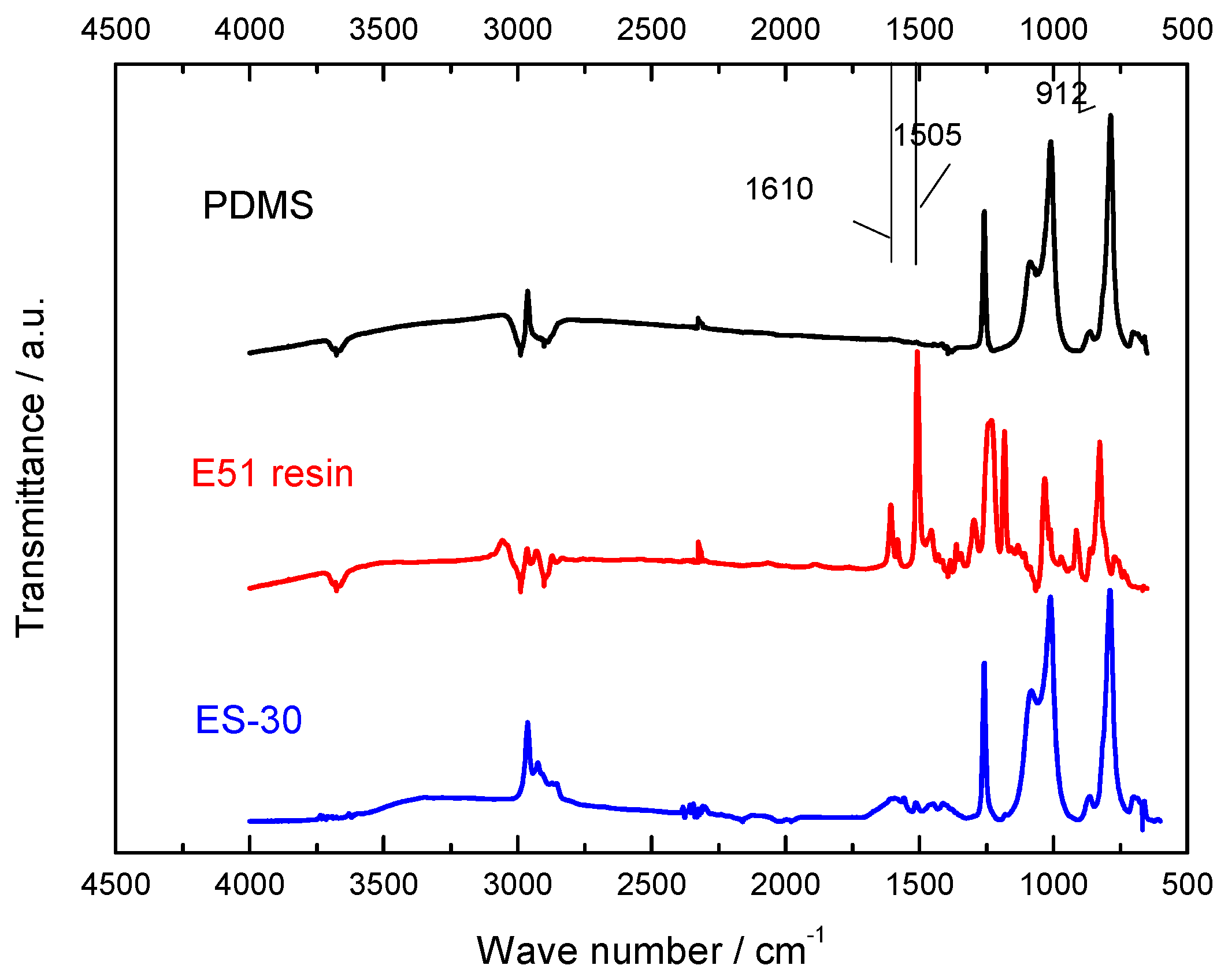
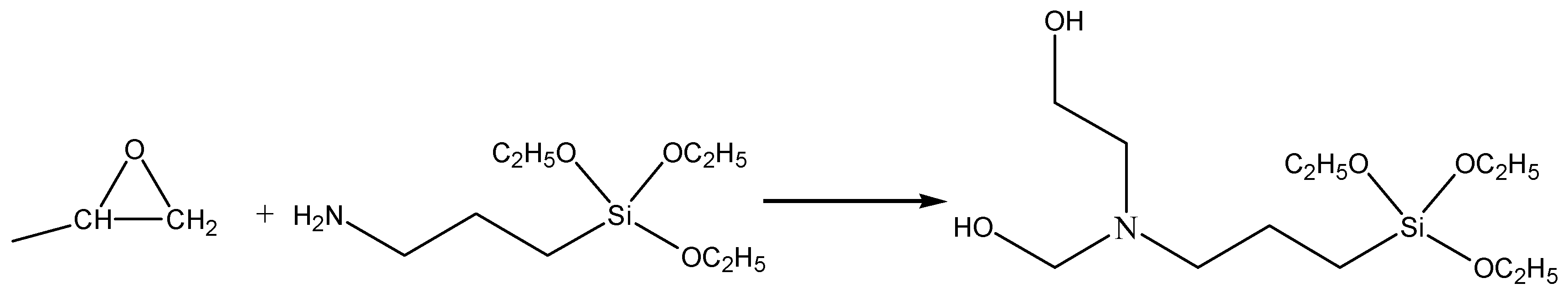
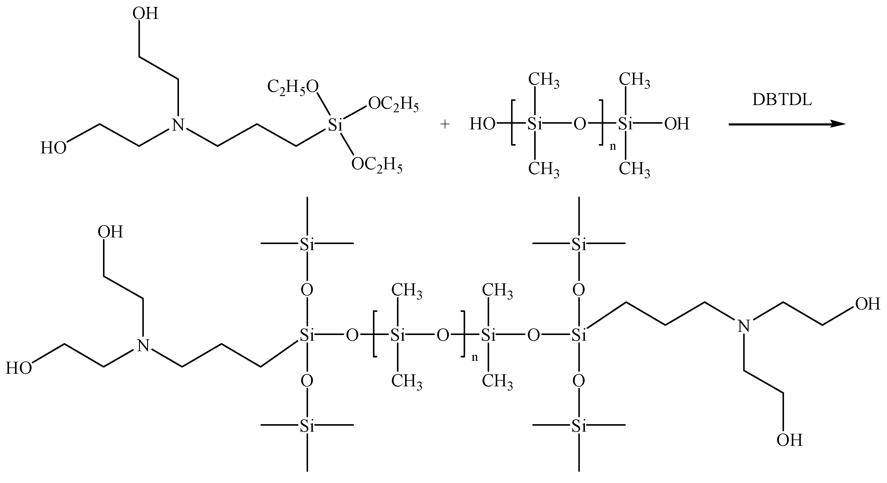
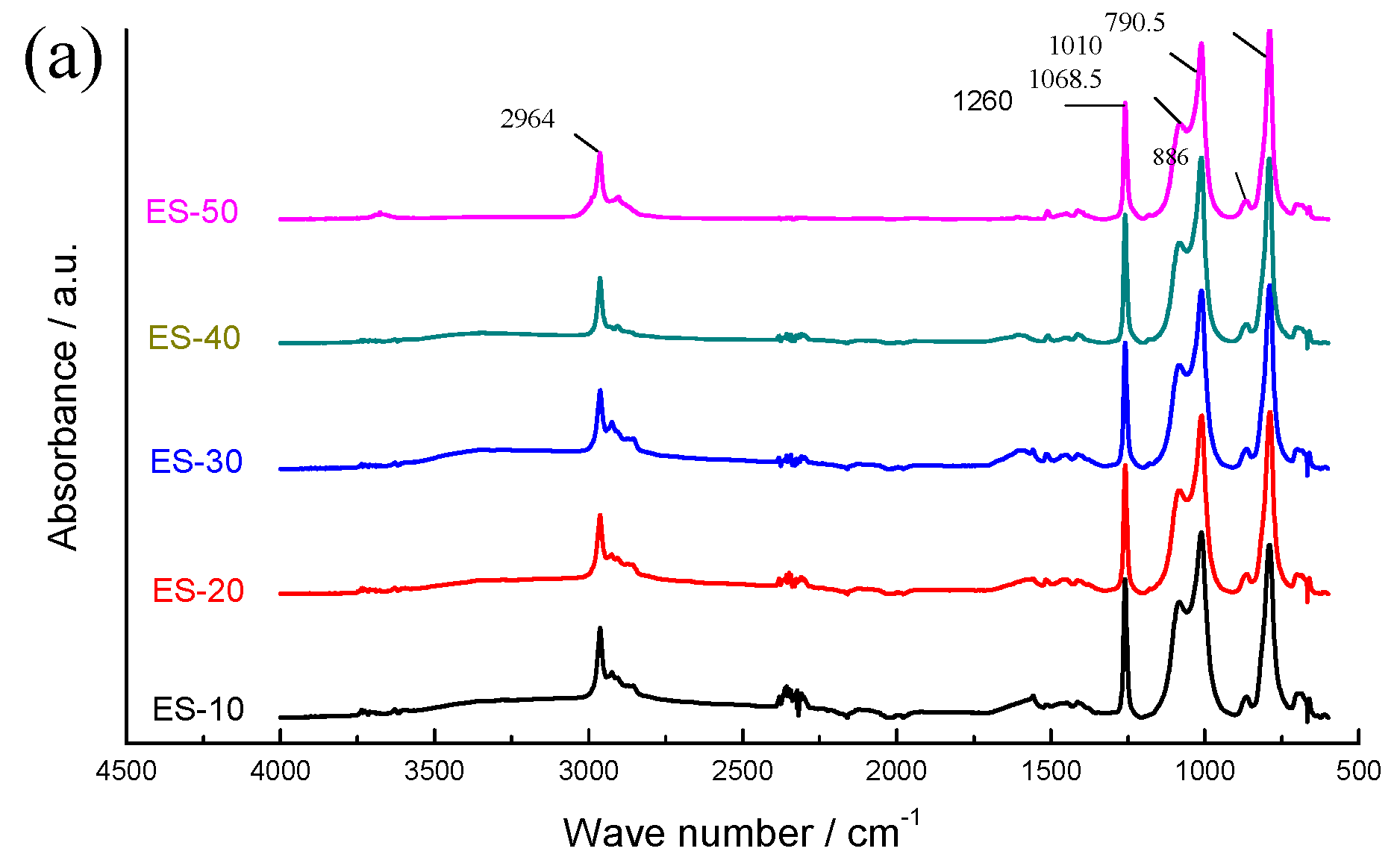
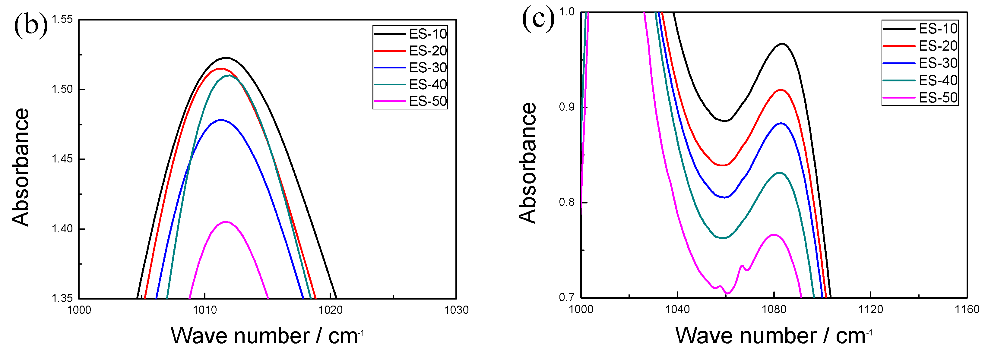
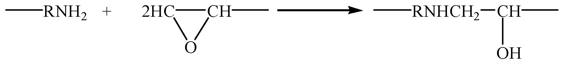
3.1. Molecular Structure
3.2. Interface Performance
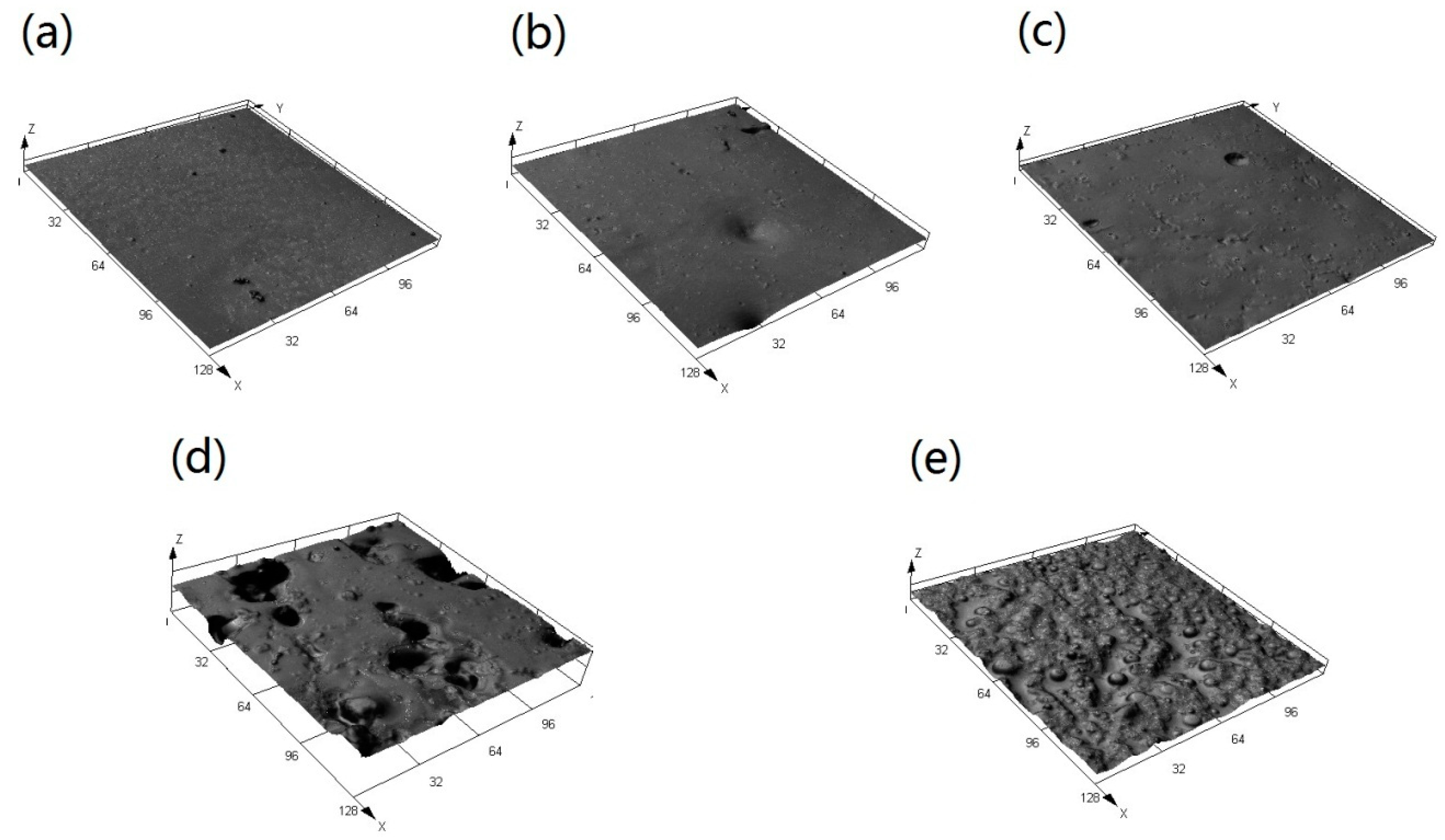
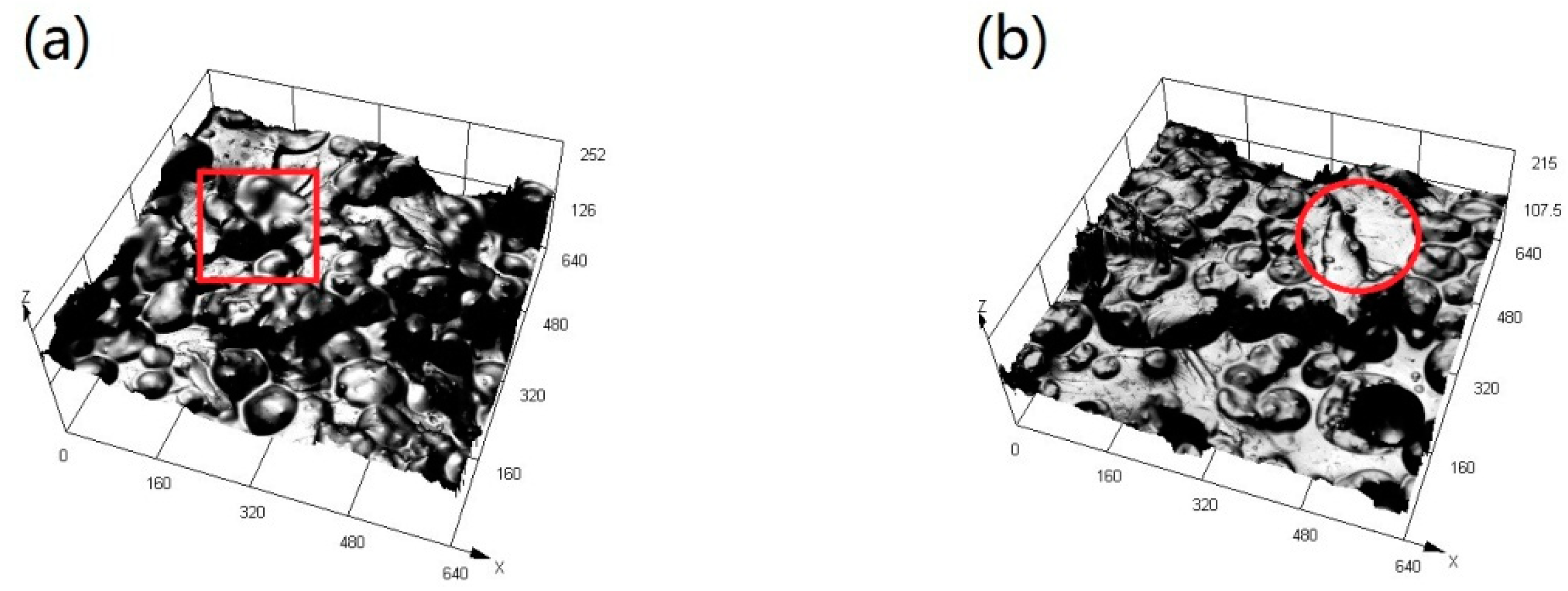
3.3. Morphology and Microstructure
3.4. Mechanical Properties
3.4.1. Basic Mechanical properties
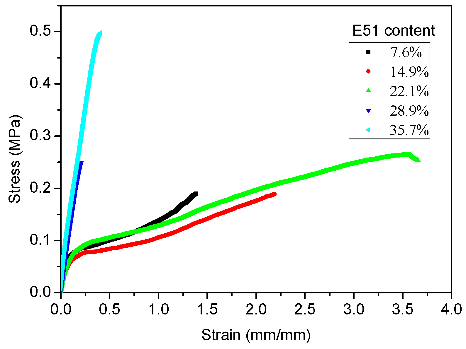
3.4.2. Tensile Properties
3.5. Marine Bacteria Adhesion
4. Discussion
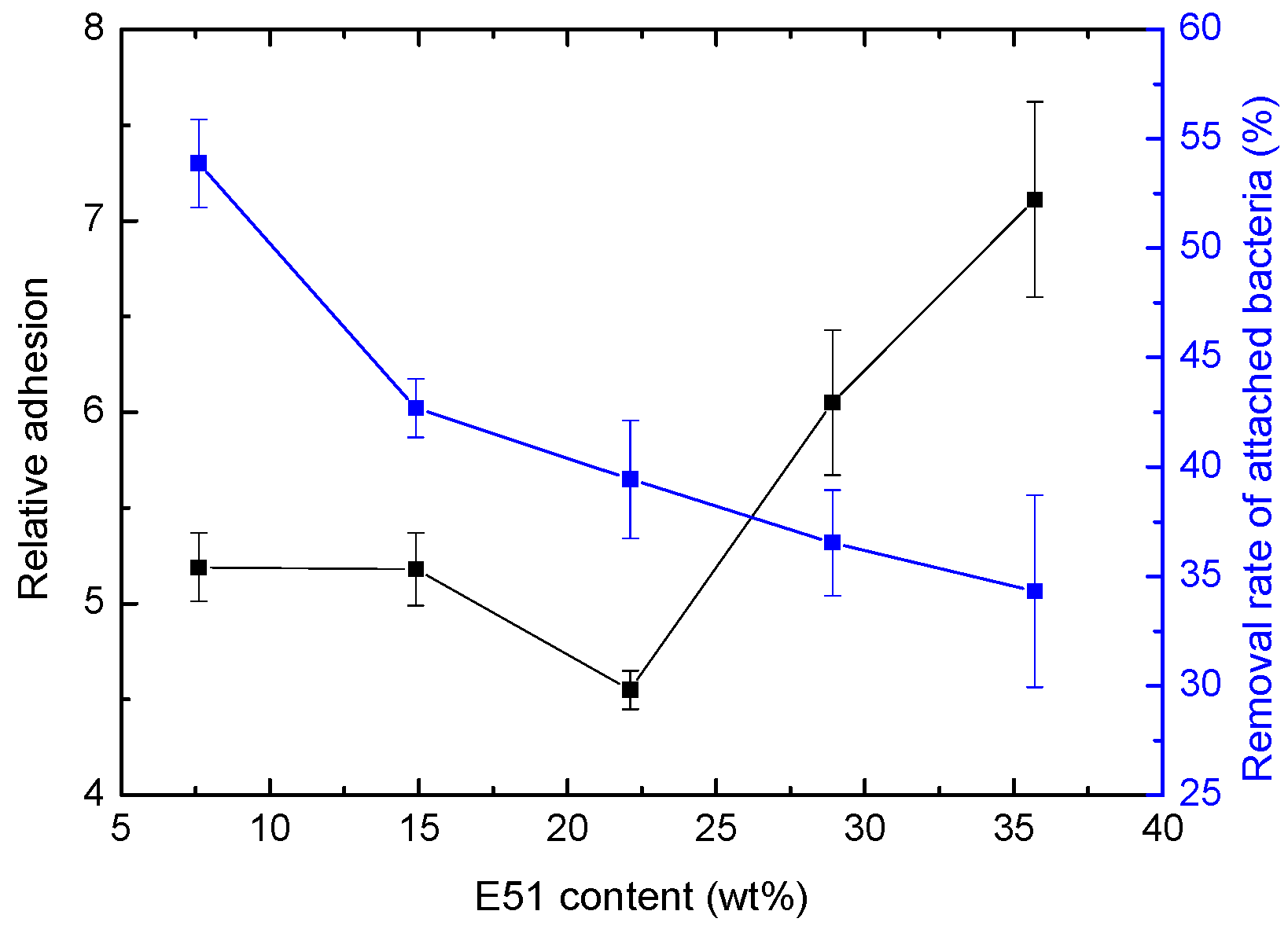
4.1. Effect of Relative Bacterial Adhesion
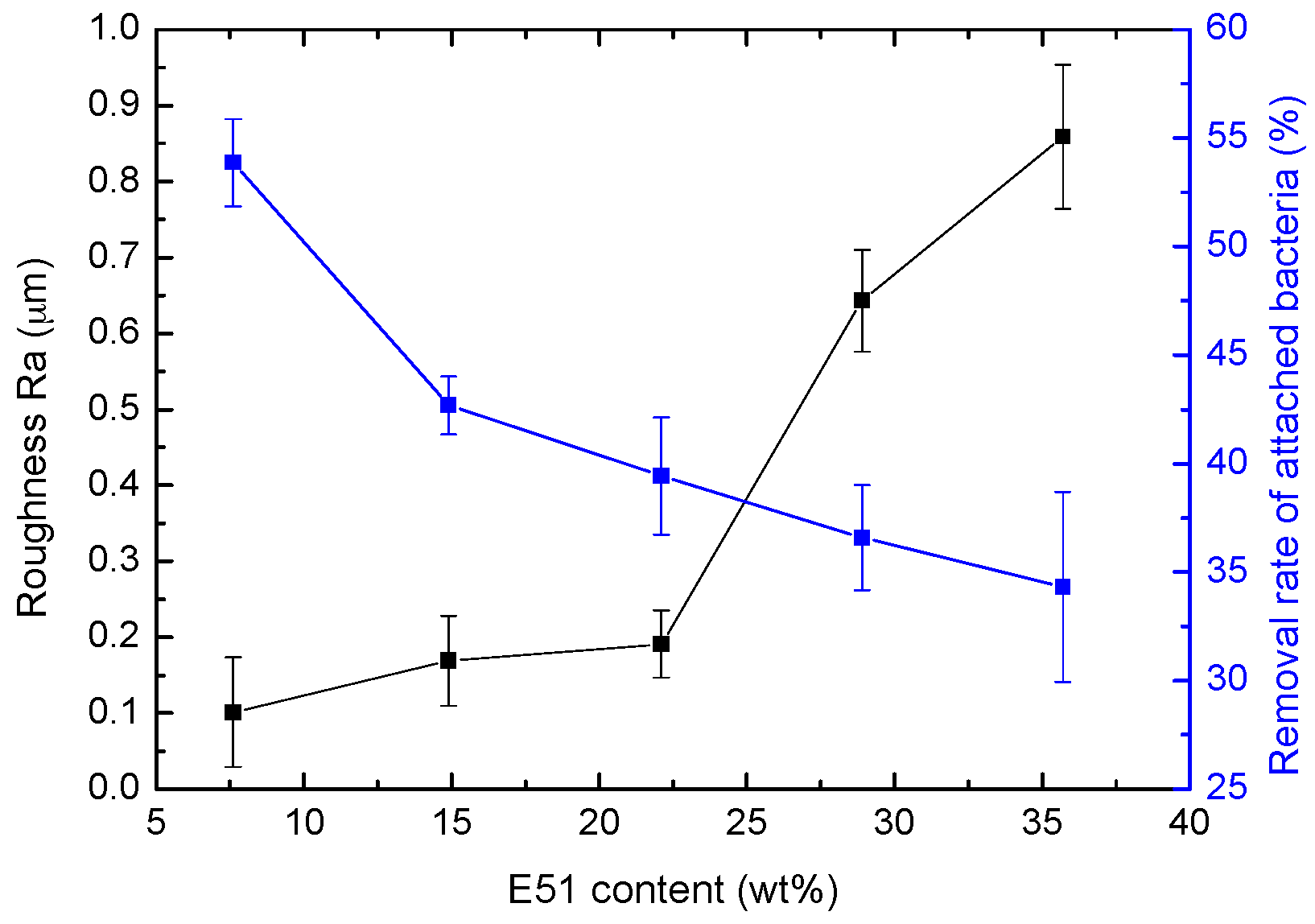
4.2. Effect of Roughness on Bacterial Adhesion
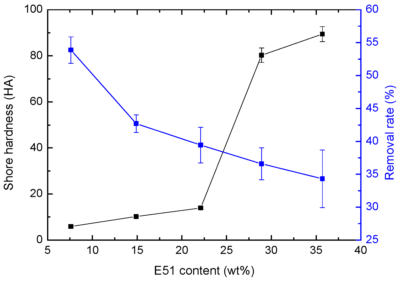
4.3. Effect of Hardness on Bacterial Adhesion
5. Conclusions
Author Contributions
Funding
Conflicts of Interest
References
- Schultz, M.P. Effects of coating roughness and biofouling on ship resistance and powering. Biofouling 2007, 23, 331–341. [Google Scholar] [CrossRef]
- Hellio, C.; Yebra, D. Advances in Marine Antifouling Coatings and Technologies; Woodhead Publishing Ltd.: Cambridge, UK, 2009; pp. 1–15. [Google Scholar]
- Eduok, U.; Faye, O.; Szpunar, J. Recent developments and applications of protective silicone coatings: A review of PDMS functional materials. Prog. Org. Coat. 2017, 111, 124–163. [Google Scholar] [CrossRef]
- Patwardhan, S.V.; Taori, V.P.; Hassan, M.; Agashe, N.R.; Franklin, J.E.; Beaucage, G.; Mark, J.E.; Clarson, S.J. An investigation of the properties of poly(dimethylsiloxane)-bioinspired silica hybrids. Eur. Polym. J. 2006, 42, 167–178. [Google Scholar] [CrossRef]
- Lejars, M.; Margaillan, A.; Bressy, C. Fouling Release Coatings: A Nontoxic Alternative to Biocidal Antifouling Coatings. Chem. Rev. 2012, 112, 4347–4390. [Google Scholar] [CrossRef] [PubMed]
- Beigbeder, A.; Degee, P.; Conlan, S.L.; Mutton, R.J.; Clare, A.S.; Pettitt, M.E.; Callow, M.E.; Callow, J.A.; Dubois, P. Preparation and characterisation of silicone based coatings filled with carbon nanotubes and natural sepiolite and their application as marine fouling re lease coatings. Biofouling 2008, 24, 291–302. [Google Scholar] [CrossRef] [PubMed]
- Laza, J.; Julian, C.; Larrauri, E.; Rodríguez, M.; Leon, L. Thermal scanning rheometer analysis of curing kinetic of an epoxy resin: 2. An amine as curing agent. Polymer 1999, 40, 35–45. [Google Scholar] [CrossRef]
- Carrozzino, S.; Levita, G.; Rolla, P.; Tombari, E. Calorimetric and microwave dielectric monitoring of epoxy resin cure. Polym. Eng. Sci. 1990, 30, 366–373. [Google Scholar] [CrossRef]
- Tan, A.; Soutar, A.; Annergren, I.; Liu, Y. Multilayer sol-gel coatings for corrosion protection of magnesium. Surf. Coat. Technol. 2005, 198, 478–482. [Google Scholar] [CrossRef]
- Zheng, S.; Li, J. Inorganic-organic sol gel hybrid coatings for corrosion protection of metals. J. Sol-Gel Sci. Technol. 2010, 54, 174–187. [Google Scholar] [CrossRef]
- Tan, A.L.K.; Soutar, A.M. Hybrid sol-gel coatings for corrosion protection of copper. Thin Solid Films 2008, 516, 5706–5709. [Google Scholar] [CrossRef]
- Ahmad, S.; Gupta, A.; Sharmin, E.; Alam, M.; Pandey, S. Synthesis, characterization and development of high performance siloxane-modified epoxy paints. Prog. Org. Coat. 2005, 54, 248–255. [Google Scholar] [CrossRef]
- Kumar, S.A.; Alagar, M.; Mohan, V. Studies on Corrosion-Resistant Behavior of Siliconized Epoxy Interpenetrating Coatings over Mild Steel Surface by Electrochemical Methods. J. Mater. Eng. Perform. 2002, 11, 123–129. [Google Scholar] [CrossRef]
- Kumar, S.A.; Narayanan, T.S. Thermal properties of siliconized epoxy interpenetrating coatings. Prog. Org. Coat. 2002, 45, 323–330. [Google Scholar] [CrossRef]
- Duraibabu, D.; Ganeshbabu, T.; Manjumeena, R.; Kumar, S.A.; Dasan, P. Unique coating formulation for corrosion and microbial prevention of mild steel. Prog. Org. Coat. 2014, 77, 657–664. [Google Scholar] [CrossRef]
- Shen, Z.; Xia, Z.; Zhang, Y. Characterization and properties of epoxy resin (E-20) modified with silicone intermediate RSN-6018. Prog. Org. Coat. 2018, 114, 115–122. [Google Scholar] [CrossRef]
- Owens, D.K.; Wendt, R.C. Estimation of the surface free energy of polymers. J. Appl. Polym. Sci. 1969, 13, 1741–1747. [Google Scholar] [CrossRef]
- GB/T 1731-1993 Determination of Flexibility of Films; SAC: Beijing, China, 1993. (In Chinese)
- ISO 1519:2011. Paints and Varnishes—Bend Test (Cylindrical Mandrel); ISO: Geneva, Switzerland, 2011.
- GB/T 9286-1998. Paints and Varnishes—Cross Cut Test for Films; SAC: Beijing, China, 1998. (In Chinese)
- ISO 2409:2013. Paints and Varnishes—Cross-Cut Test; ISO: Geneva, Switzerland, 2013.
- GB/T 1732-1993. Determination of Impact Resistance of Film; SAC: Beijing, China, 1993. (In Chinese)
- ISO 7619-1:2010. Rubber, Vulcanized or Thermoplastic—Determination of Indentation Hardness—Part 1: Durometer Method (Shore Hardness); ISO: Geneva, Switzerland, 2010.
- GB/T 528-2009. Rubber, Vulcanized or Thermoplastic—Determination of Tensile Stress-Strain Properties; SAC: Beijing, China, 2009. (In Chinese)
- ISO 37:2005. Rubber, Vulcanized or Thermoplastic—Determination of Tensile Stress-Strain Properties; ISO: Geneva, Switzerland, 2005.
- Huang, X.D.; Zhang, Z.P.; Qi, Y.H.; Sun, X.S.; Zhang, Z.W. Experiment of marine bacteria adhesion on water-based polyurethane antifouling paint. J. Dalian Marit. Univ. 2007, 33, 6–9. (In Chinese) [Google Scholar]
- Velan, T.V.T.; Bilal, I.M. Aliphatic amine cured PDMS-epoxy interpenetrating network system for high performance engineering applications—Development and characterization. Bull. Mater. Sci. 2000, 23, 425–429. [Google Scholar] [CrossRef]
- Zhou, R.; Jin, H.Y.; Gao, N.K.; Peng, Z.-R.; Qiao, G.-J.; Li, X.-Y.; Jin, Z.-H. Effect of Surface Roughness on Superhydrophobicity of Silicone Rubber Surface. China Surf. Eng. 2009, 22, 30–35. (In Chinese) [Google Scholar]
- Beaugendre, A.; Degoutin, S.; Bellayer, S.; Pierlot, C.; Duquesne, S.; Casetta, M.; Jimenez, M. Self-stratifying epoxy/silicone coatings. Prog. Org. Coat. 2016, 103, 101–110. [Google Scholar] [CrossRef]
- He, P.S. Structural Properties of Polymers; Science Press: Beijing, China, 2009; p. 267. (In Chinese) [Google Scholar]
- Selim, M.; Shenashen, M.; El-Safty, S.A.; Higazy, S.; Isago, H.; Elmarakbi, A. Recent progress in marine foul-release polymeric nanocomposite coatings. Prog. Mater. Sci. 2017, 87, 1–32. [Google Scholar] [CrossRef]
- Brady, R.F.; Singer, I.L. Mechanical factors favoring release from fouling release coatings. Biofouling 2000, 15, 73–81. [Google Scholar] [CrossRef] [PubMed]
- Scardino, A.J.; Harvey, E.; De Nys, R. Testing attachment point theory: Diatom attachment on microtextured polyimide biomimics. Biofouling 2006, 22, 55–60. [Google Scholar] [CrossRef] [PubMed]


| Sample | E51 | PDMS | LT-550 | Polyamide | Dibutyltin Dilaurate |
|---|---|---|---|---|---|
| ES-10 | 7.6 | 68.2 | 17.0 | 3.8 | 3.4 |
| ES-20 | 14.9 | 59.7 | 14.9 | 7.5 | 3.0 |
| ES-30 | 22.1 | 51.5 | 12.9 | 11.0 | 2.5 |
| ES-40 | 28.9 | 43.5 | 10.9 | 14.5 | 2.2 |
| ES-50 | 35.7 | 35.7 | 8.8 | 17.9 | 1.9 |
| Sample | E51 Content (wt %) | Contact Angle (°) | Surface Free Energy (mJ/m2) | Ra (μm) | |
|---|---|---|---|---|---|
| Water | Diiodomethane | ||||
| ES-10 | 7.6 | 113.67 ± 0.83 | 78.83 ± 1.53 | 19.68 ± 0.62 | 0.101 ± 0.072 |
| ES-20 | 14.9 | 109.06 ± 1.54 | 74.50 ± 1.17 | 20.67 ± 1.35 | 0.169 ± 0.059 |
| ES-30 | 22.1 | 114.25 ± 0.91 | 85.83 ± 1.03 | 16.45 ± 0.59 | 0.191 ± 0.044 |
| ES-40 | 28.9 | 113.17 ± 1.33 | 78.25 ± 0.47 | 18.15 ± 0.20 | 0.643 ± 0.067 |
| ES-50 | 35.7 | 112.19 ± 0.44 | 75.75 ± 1.17 | 18.87 ± 1.17 | 0.859 ± 0.095 |
| Sample | E51 Content (wt %) | Shore Hardness (HA) | Adhesion (level) | Flexibility (mm) | Impact Resistance (kg·cm) |
|---|---|---|---|---|---|
| ES-10 | 7.6 | 5.90 ± 0.26 | 1 | 1 | 50 |
| ES-20 | 14.9 | 10.23 ± 0.25 | 1 | 1 | 50 |
| ES-30 | 22.1 | 13.97 ± 0.56 | 1 | 1 | 50 |
| ES-40 | 28.9 | 80.20 ± 3.16 | 1 | 1 | 50 |
| ES-50 | 35.7 | 89.40 ± 3.28 | 1 | 1 | 50 |
| Sample | E51 Content (wt %) | Elastic Modulus (MPa) | Fracture Elongation (%) | Fracture Strength (MPa) |
|---|---|---|---|---|
| ES-10 | 7.6 | 1.37 ± 0.05 | 130.45 ± 6.96 | 0.19 ± 0.02 |
| ES-20 | 14.9 | 1.30 ± 0.01 | 211.84 ± 3.88 | 0.19 ± 0.02 |
| ES-30 | 22.1 | 1.26 ± 0.01 | 357.23 ± 2.84 | 0.27 ± 0.01 |
| ES-40 | 28.9 | 2.02 ± 0.23 | 17.88 ± 0.24 | 0.24 ± 0.02 |
| ES-50 | 35.7 | 2.68 ± 0.22 | 38.20 ± 0.77 | 0.48 ± 0.04 |
| Sample | Original Image | Processed Image | ||
|---|---|---|---|---|
| Rinsed | Washed | Rinsed | Washed | |
| ES-10 |  | 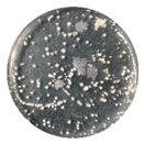 |  | 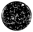 |
| ES-20 | 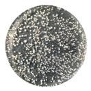 |  | 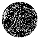 |  |
| ES-30 | 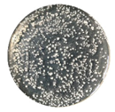 | 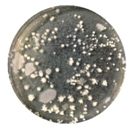 | 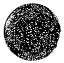 | 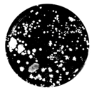 |
| ES-40 | 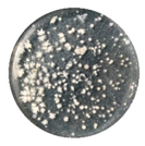 |  | 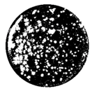 | 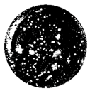 |
| ES-50 | 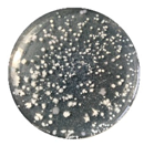 |  | 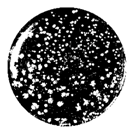 | 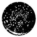 |
| Sample | E51 Content (wt %) | Colony Concentrationv (×106 CFU·mL−1) | Removal Rate (%) | |
|---|---|---|---|---|
| Rinsed | Washed | |||
| ES-10 | 7.6 | 110.5 ± 9.4 | 50.9 ± 2.1 | 53.87 ± 2.02 |
| ES-20 | 14.9 | 125.3 ± 6.4 | 71.8 ± 3.5 | 42.69 ± 1.34 |
| ES-30 | 22.1 | 129.4 ± 4.1 | 78.4 ± 9.2 | 39.43 ± 2.69 |
| ES-40 | 28.9 | 93.2 ± 16.8 | 59.1 ± 8.4 | 36.59 ± 2.42 |
| ES-50 | 35.7 | 97.7 ± 17.5 | 64.1 ± 7.2 | 34.32 ± 4.38 |
© 2020 by the authors. Licensee MDPI, Basel, Switzerland. This article is an open access article distributed under the terms and conditions of the Creative Commons Attribution (CC BY) license (http://creativecommons.org/licenses/by/4.0/).
Share and Cite
Zhao, R.; Zhang, Z.; Qi, Y. Influence of Epoxy Content on the Properties and Marine Bacterial Adhesion of Epoxy Modified Silicone Coatings. Coatings 2020, 10, 126. https://doi.org/10.3390/coatings10020126
Zhao R, Zhang Z, Qi Y. Influence of Epoxy Content on the Properties and Marine Bacterial Adhesion of Epoxy Modified Silicone Coatings. Coatings. 2020; 10(2):126. https://doi.org/10.3390/coatings10020126
Chicago/Turabian StyleZhao, Ruikang, Zhanping Zhang, and Yuhong Qi. 2020. "Influence of Epoxy Content on the Properties and Marine Bacterial Adhesion of Epoxy Modified Silicone Coatings" Coatings 10, no. 2: 126. https://doi.org/10.3390/coatings10020126
APA StyleZhao, R., Zhang, Z., & Qi, Y. (2020). Influence of Epoxy Content on the Properties and Marine Bacterial Adhesion of Epoxy Modified Silicone Coatings. Coatings, 10(2), 126. https://doi.org/10.3390/coatings10020126