Article

Optimizing Heat Treatment for Electroplated NiP and NiP/SiC Coatings

by
Donya Ahmadkhaniha
1,*,
Fredrik Eriksson
2 and
Caterina Zanella
1
1
Department of Material and Manufacturing, School of Engineering, Jönköping University, P.O. Box 1026, Gjuterigatan 5, SE-551 11 Jönköping, Sweden
2
Department of Physics, Chemistry and Biology (IFM), Linköping University, SE-581 83 Linköping, Sweden
*
Author to whom correspondence should be addressed.
Coatings 2020, 10(12), 1179; https://doi.org/10.3390/coatings10121179
Submission received: 13 November 2020 / Revised: 26 November 2020 / Accepted: 27 November 2020 / Published: 1 December 2020
(This article belongs to the Section Surface Characterization, Deposition and Modification)

Abstract

:
NiP (P > 10 wt.%) coatings are amorphous coatings whose structure can be transformed by heat treatment into a crystalline structure and hardened by precipitation of Ni3P. In this study, NiP coatings and composite ones with SiC nanoparticles were produced by electrodeposition, and their structural transformation by heat treatment was studied using differential scanning calorimetry (DSC) and X-ray diffraction (XRD). The microhardness and the scratch and corrosion resistance of the coatings were evaluated and compared before and after different heat treatments. The results showed that in as-plated condition, the addition of SiC particles in the coatings did not modify the microstructure, microhardness, or electrochemical behavior. However, the SiC particles’ role was disclosed in combination with heat treatment. Composite coatings that were heat treated at 300 °C had higher microhardness and scratch resistance than the pure NiP one. In addition, composite coatings maintained their scratch resistance up to 400 °C, while in the case of the NiP ones, there was a reduction in scratch resistance by heating at 400 °C. It was also concluded that heating temperature has the main role in hardness and corrosion resistance of NiP and composite coatings, rather than heating time. The optimum heat-treatment protocol was found to be heating at 360 °C for 2 h, which resulted in a maximum microhardness of about 1500 HV0.02 for NiP and its composite coating without sacrificing the corrosion resistance.

1. Introduction

NiP coatings have mainly been produced by electroless deposition, which can deposit a uniform coating on samples with recesses and complex geometry [1,2,3]. However, there are some challenges in controlling electroless nickel-plating solutions. Electroless solutions have a complex composition, including complexing agents, buffering agents, stabilizers, and reducing agents, which makes their production, maintenance, and disposal sophisticated and expensive. In addition, electroless plating needs a high operating temperature, though it has a low deposition rate. Due to these challenges of electroless plating, electroplating, which was developed by Brenner et al. [4] for the deposition of alloy coatings, has gained attention as an alternative deposition process. Electrodeposition can deposit a thick layer of alloy in a relatively short time by means of a simple process [5].
There have been several kinds of research on electrodeposition of NiP coatings. Harris and Dang [6] studied the mechanism of phosphorus deposition during electrodeposition of NiP alloys. Lin et al. [7] examined the effect of different current profiles on phosphorus content and current efficiency of the deposition. The effect of electrodeposition parameters on the structural characteristic of NiP coating was investigated by Bredael et al. [8], and they found a transition from high to low phosphorus content in the NiP coatings by increasing local current density. The phosphorus content, which is affected by the electrodeposition parameter, has a key role in determining the NiP coating’s properties. The coatings with P > 10 wt.%, known as high-phosphorus coatings, have an amorphous structure. As-plated Ni high-P coatings are well suited for general applications [9,10,11,12], especially in corrosive environments, but their hardness (around 500 HV) and wear resistance are still not sufficient for demanding situations. Hence, various reinforcing particles, such as SiC [13], TiN [14], TiO2 [15], SiO2 [16], Si3N4 [17], WC [18], Al2O3 [19], B4C [20], and CNTs [12], have been incorporated into NiP coatings to enhance their mechanical and tribological properties. In particular, SiC particles have been extensively used due to their mechanical properties and economical cost. For this reason, several researchers have focused on the properties of NiP coatings with the addition of micron and sub-micron SiC particles [9,21,22,23].
Heat treatment can also enhance the hardness of Ni high-P coatings, since the amorphous super-saturated structure can be crystallized by heat-treatment, and the hardness can be enhanced up to 1000 HV by crystallization of NiP and precipitation of Ni3P [24,25,26,27]. The crystallization and phase transformation of NiP coatings during thermal treatment have been the subjects of various investigations. It has been shown that alloy compositions and heat-treatment conditions could affect both the microstructure and crystallization behavior of the coatings [28,29,30], which, in turn, influence the coating properties. Hur et al. [31] showed that more than one intermediate phase (Ni3(P,Ni) or Ni5(P,Ni)2) was involved in the crystallization process. The formation of other intermediate phases, such as Ni7P3, Ni12P5, and Ni5P2, has been also reported [30]. It was also indicated that low-phosphorus-containing Ni coatings decompose directly into a mixture of crystalline Ni and Ni3P through heat treatment at temperatures higher than 380 °C. On the other hand, high-phosphorus-containing coatings first transform into a metastable intermediate NixPy phase, which subsequently transforms into Ni and Ni3P at higher temperatures [32].
Although the addition of ceramic particles and application of heat treatment can increase the hardness of NiP coatings, they can deteriorate the corrosion resistance of the coatings due to the formation of voids [33] and microcracks [34,35,36] in the coating. Hence, the effects of ceramic particle addition, as well as heat-treatment parameters, should be studied to find the proper combination that enhances their microhardness without sacrificing their corrosion resistance. In this study, the effects of SiC particle size and different heat treatments on the hardness and the scratch and corrosion resistance of NiP coatings were studied to find the optimized condition that leads to the best combination of hardness and corrosion resistance.

2. Materials and Methods

2.1. Sample Preparation and Deposition Methods

NiP (P > 10 wt.%) alloys were electrodeposited through direct current plating from a modified Watts bath containing NiSO4∙7H2O, NiCl2∙6H2O, H3PO3, H3BO3, and two additives (saccharin and sodium dodecyl sulfate) [21]. Plating was carried out in a circular cell (2 liters) on 25 cm2 low-carbon steel plates. The following pre-treatments were applied on the steel substrates: mechanically grinding with SiC papers (grades #500 and #800), ultrasonically cleaning in an alkaline soap, rinsing with distilled water, immersing 8 min in 2.5 M H2SO4 at 50 °C, and rinsing with distilled water; then, the samples were immersed in the bath. A vertical Ni anode and cathode with a distance of 12 cm from each other were chosen for plating. The pH of the bath was kept constant at 2.15 by adding sulfuric acid or sodium hydroxide. A total of 20 g/L of silicon carbide powder (β-SiC; provided by “Get Nano Materials”, Saint-Cannat, France), with an average particle size of 50 or 100 nm, was added to the bath 24 h before plating in case of composite plating. The composite bath was stirred (at 250 rpm) with a magnetic stirrer before and during plating. The current density of 4 A/dm2 and a bath temperature of 70 °C were chosen for the deposition. The deposition was carried out for 1 h to have a coating thickness of 25 µm, and three different coatings were obtained, which were denoted as NiP, NiP/SiC50, and NiP/SiC100, respectively, in this study.
The effect of heat treatment (HT) on the properties of the coatings was studied by heating the samples with a heating rate of 30 °C/min in a controlled argon atmosphere (to reduce the possibility of oxide layer formation) at temperatures of 300, 360, and 400 °C for different times.

2.2. Coating Characterization

The surface morphology and coating composition were investigated through scanning electron microscopy (SEM, JEOL 7001F, Akishima, Japan) equipped with an energy dispersive spectrometer (EDS, EDAX, Mahwah, NJ, USA). A surface profilometer (Surtronic 3+, Taylor Hobson, UK) was used to measure surface roughness. Differential scanning calorimetry (DSC; Netzsch DSC 404 C, Selb, Germany) with a 30 °C/min heating rate in the temperature range of 25 to 550 °C with argon as a protective medium was used to study the structural transformation of the coatings. X-ray diffraction was performed using a Panalytical X’Pert diffractometer (Empyrean diffractometer, Eindhoven, The Netherlands) with Cu-Kα X-rays (λ = 1.54 Å) to investigate the microstructure of the coatings. The in-situ investigations of phase transitions and precipitation were carried out using the high-temperature sample stage DHS1100 from Anton Paar (Graz, Austria). The microstructure of the samples was analyzed at room temperature, and then samples were heated using a ramping rate of 40 °C/min, and the microstructure was analyzed at different temperatures. In addition, to study the effect of heating time on the coatings’ microstructure, some samples were heated at 300 °C from 1 to 7 h, and their microstructures were analyzed at different heating times. All diffraction peaks in the range of 2θ = 25°−100° were used for phase analysis; however, for clarity, only a smaller representative region between 2θ = 35°−55° is shown here.
The hardness was measured on the coating’s cross-section using Berkovich and Vickers indenters (NanoTestTM Vantage, 40.36, Micro Materials, Wrexham, UK) with a dwell time of 10 s and indentation loads of 10 and 200 mN, respectively. A total of 15 measurements were performed on two different samples under the same conditions to obtain the average microhardness values.
The coating nanohardness was estimated according to Equation (1), where H is the coating hardness, Pmax is the maximum load, and A is the contact area under the load [37].
H = P m a x A
The elastic module of the coating, Es, was calculated from the reduced Youngs modulus (Er) according to [37,38].
1 E r = 1 υ s 2 E s + 1 υ i 2 E i
Er considers that elastic displacements occur in both the specimen and the indenter, Ei,s and νi,s are the elastic modulus and Poisson ratio for the indenter and the specimen, respectively. In this study, Ei is 1140 GPa, and νi is 0.07 [39].
A scratch test was carried out using a conical diamond indenter (100 µm diameter) with a constant load of 4 N as well as a progressive load (0 to 8 N) at a scanning velocity of 10 µm/s and loading rate of 30 mN/s to investigate the scratch resistance and adhesion of the coatings to the substrate. The scratch scars were investigated by SEM and AFM (atomic force microscope; Park, NX10, Suwon, Korea).
Potentiodynamic polarization (Ivium, Netherlands) with Ag/AgCl (3 M KCl, 0.21 vs. SHE/V) and platinum electrodes as the reference and counter electrodes, respectively, was used for the electrochemical tests. As working electrodes, 1 cm2 of coatings were exposed to 3.5% NaCl. After 20 min of immersion, polarization from 50 to 1000 mV with respect to the open circuit potential (OCP) was run with a scan rate of 0.2 mV/s. The tests were repeated at least twice on different specimens of the same coating.

3. Results and Discussion

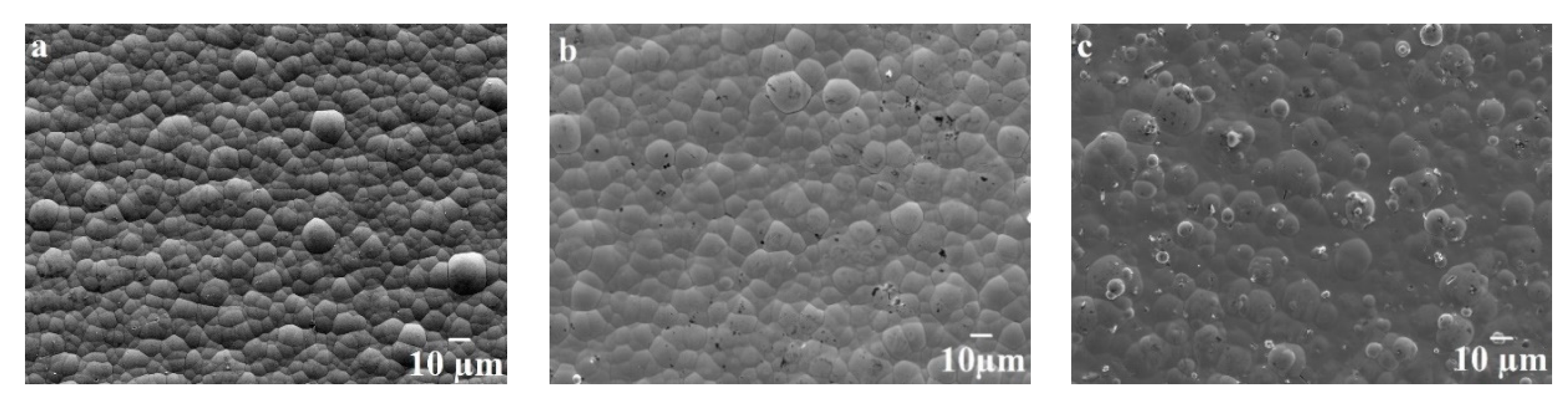
3.1. Morphology and Composition

Figure 1 shows the surface morphology of the NiP and composite coatings, which demonstrates a nodular morphology for all coatings. The surface roughness of NiP coatings was increased from 0.35 µm in NiP to 0.56 µm in the NiP/SiC100 coating. Matik [16] and Chang et al. [40] also observed a rougher surface by the addition of Si3N4 and SiC to the NiP matrix. During electrodeposition, the NiP matrix grows around the SiC particles. After finishing the deposition process, some edges of particles remain uncovered, which results in a higher surface roughness than pure NiP coating.
The SiC 50 nm particles are not observed in the SEM image (Figure 1b) due to their small size, while the small white areas seen in Figure 1c are related to SiC 100 nm particles.
The composition of the coatings was measured by EDS analysis on the coating’s surface.
The previous study [41] showed that the composition of NiP coatings depends on the bath charge, and the EDS results in Figure 2 show that co-deposited the SiC 100 nm particles are much more scattered than the SiC 50 nm particles. The amount of co-deposited SiC 100 nm changed noticeably from one sample to another one, while for SiC 50 nm, it was approximately constant. In this study, co-deposition of SiC100 was more dependent on the bath charge than SiC50, which can be the reason for the scattered wt.% values. In addition, the difference between NiP/SiC50 and SiC100 can be due to the different batches or the differences in the manufacturing process, which can result in different surface properties of the particles.
In this study, in order to have comparable results, the samples with similar wt.% of P and close wt.% of SiC were chosen for more characterization.

3.2. DSC

DSC was used to study the phase transformation during the heat treatment of the coatings (with 11 wt.% P and 1 wt.% SiC), and the results are presented in Figure 3. NiP coatings showed two exothermic peaks (Figure 3a), while the NiP/SiC composite coatings exhibited one exothermic peak. These exothermic peaks are related to the transformation of amorphous NiP into crystalline Ni and the precipitation of the Ni3P phase in the matrix, as identified by the XRD analysis presented in Section 3.3. The position of the exothermic peak for the phase transformation in the NiP coatings depends on the phosphorus content and the heating rate [16]. Small changes in the composition of the composite coating influence the crystal transformation temperature of the coating. Balaraju et al. [42] reported that adsorption of second-phase particles on the NiP surface reduces the active surface area available for the reduction of nickel and phosphorus. The reason for the different DSC curves of the NiP and composite coatings has not been clarified yet. For better clarification, the NiP coatings with different P content (9 wt.%, the least P content for Ni high-P coatings, 14 wt.%, the highest P content achieved in the coatings, and 11 wt.% in between) were tested (Figure 3b). The peak around 340 °C (the temperature at the tip of the peak) was obtained in all conditions. In contrast, the small peak at 400 °C is seen in some conditions, and there is not a clear trend between the P content and the second peak.
There was not any difference in the DSC graphs of the NiP/SiC coatings with 0.5 wt.% and 3 wt.% SiC particles (Figure 3c). According to these results, the size and the amount of SiC particles do not affect the phase transformation. However, their existence changes the transformation behavior, since, with the same amount of P content, different DSC results were obtained with respect to the NiP coatings.

3.3. XRD

The XRD patterns of the NiP and composite coatings at room temperature and heat treated at different temperatures for 1 h are shown in Figure 4. At room temperature, all coatings demonstrated a broad diffraction peak centered around 2θ = 44.5°, corresponding to nanocrystalline Ni domains in an amorphous phase. By alloying Ni with high P, the Ni lattice distorts, which results in a disordered structure. The XRD pattern obtained for the as-plated NiP composite coating is similar to that of the pure NiP coating, confirming that co-deposition of SiC does not affect the coating crystallization in the as-plated state.
The XRD patterns of the heat-treated coatings at 100, 200, and 300 °C for 1 h are similar to the ones at room temperature. It should be noted that the peaks appearing at 2θ = 35.9°, 37.8°, and 43.9° are related to the AlN heating filament. At 400 °C, however, sharp diffraction peaks related to crystalline Ni and Ni3P phases appeared. This structure remains during further heat treatment at 500 °C, and also after cooling to room temperature (not shown here). By comparing the XRD patterns of the coatings, it can be seen that the crystallization of Ni and precipitation of Ni3P phases are the same in the NiP and NiP/SiC50 or 100 composite ones. The diffraction peaks at 2θ = 44.6° and 51.8° originate from the diffraction of the Ni (111) and (200) lattice planes, respectively, while the others are related to Ni3P and the AlN heating filament.
Keong et al. [25] reported that coatings containing > 10 wt.% phosphorus transform from amorphous to one or more metastable phases (Ni3(P,Ni) and/or Ni5(P,Ni)2) before the formation of stable Ni and Ni3P phases. This behavior was not observed in this study, and this could be because of either temperature steps that were too significant or measurement times that were too long, such that the transformation occurred before was recorded.
The DSC results showed that the phase transformation occurred below 400 °C, and the XRD results demonstrated that at 400 °C, full crystallization and precipitation occurred. Therefore, samples were heated at a lower temperature (300 °C) for a longer time, up to 7 h, to study the effect of heating time on the coating microstructure. Isothermal XRD patterns of the coatings are displayed in Figure 5. It can be observed that XRD patterns of the coatings heated at 300 °C for 1 h are different for the NiP and composite coatings. The NiP coatings remained nanocrystalline, while in the composite coatings, diffraction peaks corresponding to the Ni3P and Ni phases appeared. There was no change in the XRD patterns except for minor changes in peak intensities by heating the coatings for more than 2 h.
The combined results of isothermal heating and DSC show that addition of SiC particles to the NiP matrix results in simultaneous crystallization of Ni and precipitation of Ni3P. However, in the case of the NiP coatings, crystallization of Ni is faster than the precipitation of Ni3P, explaining the existence of two separate exothermic peaks in the DSC measurement of the NiP coating.

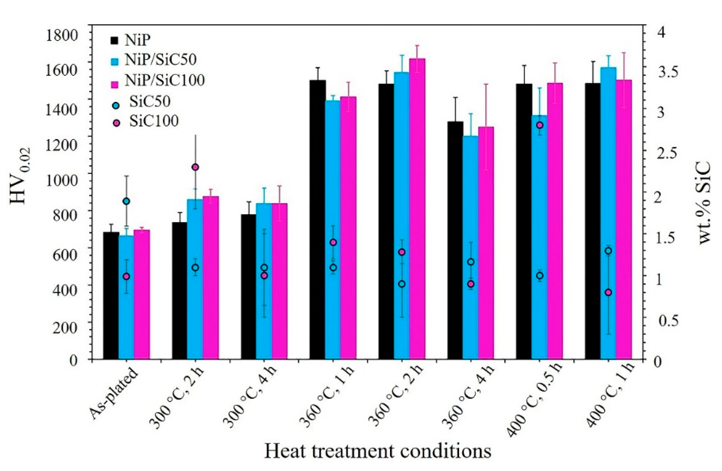
3.4. Microhardness and Nanoindentation
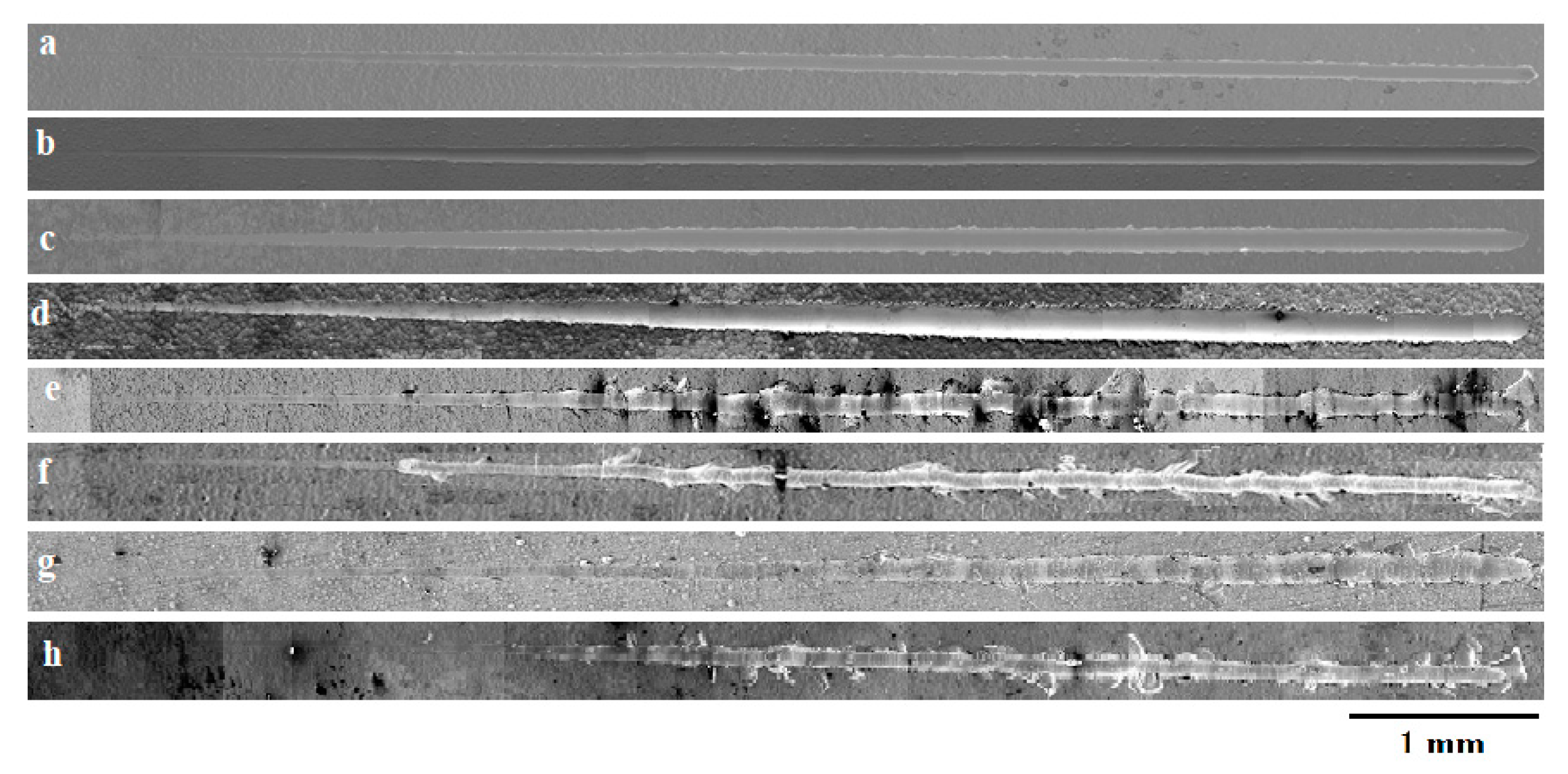
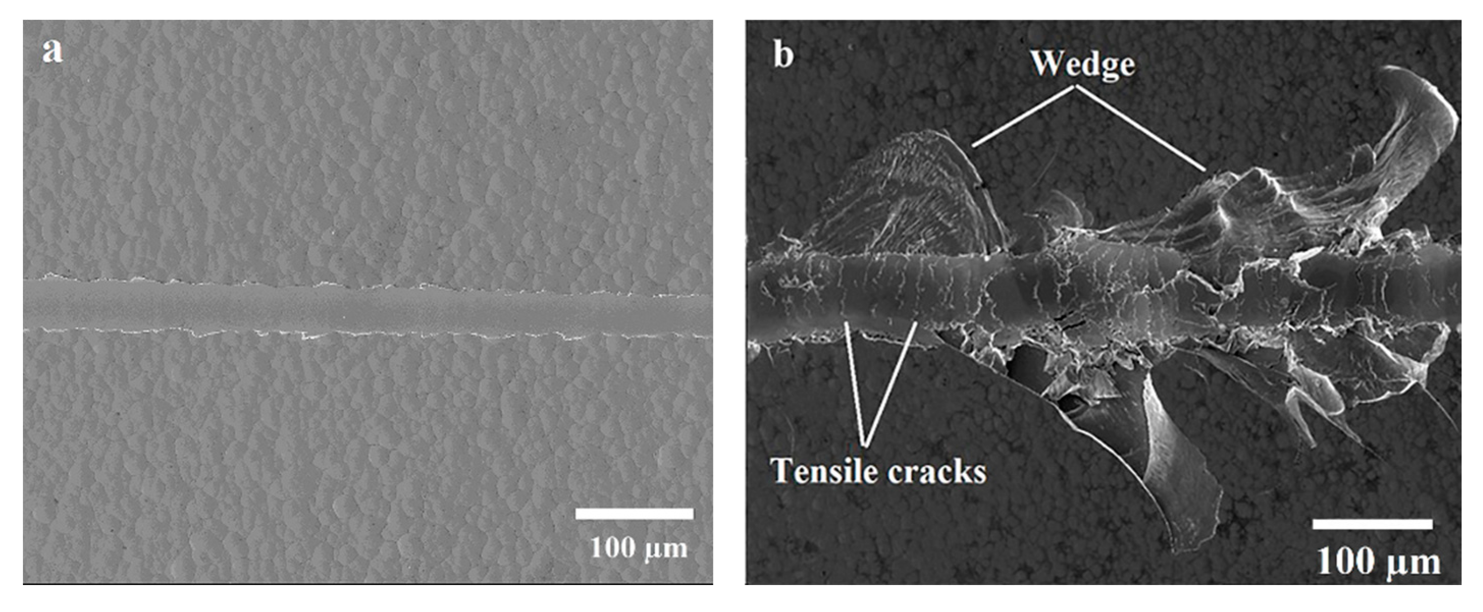
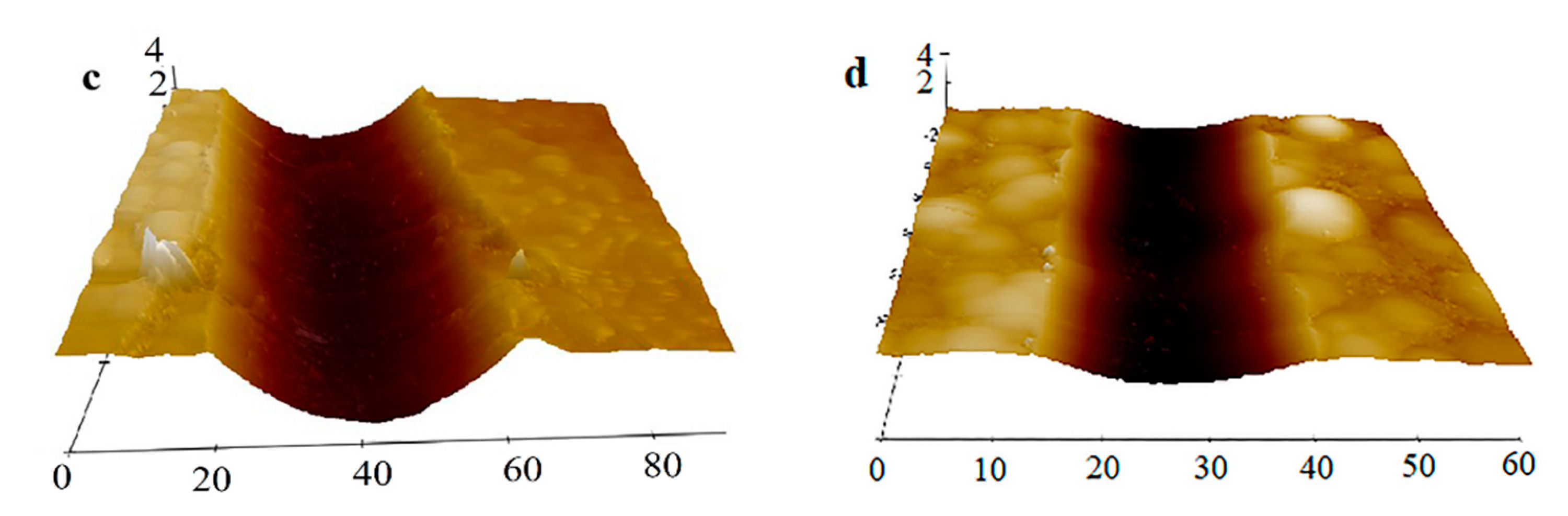
The microhardness of the coatings was measured using a Vickers indenter on the cross-section of the coating, and the results are shown in Figure 6. As seen in Figure 6, the microhardness of the NiP and composite coatings is similar, around 700 HV0.02, and addition of SiC of nano or sub-micron size did not affect the microhardness values of the coating. Even higher percentages of SiC50 (2 wt.%) with respect to SiC100 (1 wt.%) did not influence the microhardness values of as-plated coatings.
The heat-treatment procedures were designed based on the results from DSC and XRD, and the hardness of heat-treated samples was measured. According to XRD, crystallization and precipitation occurred after heating at 300 °C for 2 h, and increasing the heating time did not affect the microstructure. The DSC results showed that after 360 °C, phase transformation happened in all coatings. Therefore, the samples were heat treated at 300 °C for 2 and 4 h, at 360 °C for 1, 2, and 4 h, and at 400 °C for 0.5 and 1 h. The temperature of 400 °C was chosen to compare the results with the standard industrial heat-treatment procedure for these coatings.
Heat treatment at 300 °C for 2 h increased the microhardness of NiP coating slightly, while more of an effect can be seen in the case of the composite coatings. Increasing the heating time at 300 °C did not change the microhardness values. These results are in agreement with the XRD results (Figure 5).
Heat treatment at 360 °C resulted in the maximum hardness for all coatings, and by increasing the heating time to 4 h, a small reduction could be seen in the hardness values, which could be due to the grain growth of the matrix.
The microhardness values for the heat treatment at 400 °C (0.5 or 1 h) are similar to the ones achieved by heating at 360 °C for 1 or 2 h.
It is seen that the microhardness values of the NiP and composite coatings in as-plated and heat-treated conditions are similar (including the error bars). In addition, there is no clear relation between the SiC content and its size with respect to hardness values. Low co-deposition or agglomeration and uneven distribution of the SiC particles in the coating reduced their role in dispersion hardening, which was also observed by Chou et al. [43]. However, the role of the particles in hardening can be seen by heating at 300 °C for 2 h, where they encourage faster precipitation, as confirmed by XRD results (Figure 5).
According to these results of heat treatment, due to the crystallization of the matrix and precipitation of the hard Ni3P phase, the microhardness increased. In addition, the heating temperature has a more significant impact on hardness values than the heating time. Heating at 360 °C for 1 or 2 h can ensure the full crystallization of the matrix and a high fraction of Ni3P precipitation with less grain growth of the matrix.
Nanoindentation was carried out on the cross-section of these coatings to study the influence of SiC particles as well as heat treatment (360 °C for 2 h) on the mechanical properties of the matrix. Figure 7 shows the typical load versus depth curve of as-plated and heat-treated coatings, in which residual depth (hr) and maximum depth (hmax) are shown. As-plated coatings exhibit similar hr and hmax values of approximately 190 and 265 nm, and through heat treatment, hr and hmax were reduced to about 130 and 200 nm, respectively. The lower residual depth of heat-treated coatings indicates their higher hardness. Moreover, there is a displacement in the as-plated coatings during the pause time at the maximum load, which is a bit higher for NiP than the composite ones, while this displacement was not seen in the case of heat-treated coatings.
According to the results of Sribalaji et al. [44], if the plastic work fraction (WP/WT) is more than 0.5, such materials are considered to be ductile materials that deform plastically and produce more pile-up. The fraction of plastic work can be determined by Equation (3).
W P W T = h r h m a x
where WP is the plastic work, WT is the total work, hr is the residual depth, and hmax represents the maximum depth of indentation.
In this study, the WP/WT values for all coatings (as-plated and heat-treated) are higher than 0.5 (see Table 1), and the values of plastic work fractions did not change significantly through heat treatment. Hence, Equation (3) cannot explain the behavior of the NiP and composite coatings.
Upon heat treatment, the elastic modulus value of as-plated coating significantly increased, as seen in Table 1. This increase in elastic modulus is due to the crystallization of the Ni matrix and precipitation of the Ni3P phase by heat treatment. The NiP and composite coatings have a similar nanohardness and elastic modulus. Since all coatings have identical behavior during nanoindentation, it seems that the co-deposition and size of SiC particles would not influence the mechanical behavior of the matrix by blocking any dislocations in particular or by introducing changes in the metal microstructure or microstrain. These observations are in agreement with the results from Alexis et al. [23].
The absence of dispersion hardening in composite coatings might be due to the low co-deposition values or uneven dispersion and agglomeration of SiC particles. According to these results, precipitation hardening is the main hardening mechanism in NiP coating.
The H/E ratio (hardness (H) and young modulus (Es)) can be used to pre-assess the wear resistance of coatings. It has been shown that the best wear resistance is observed with a higher H/E ratio [45,46,47]. Beake et al. [48] also observed that coatings with a higher H/E ratio exhibit lower plasticity and, thus, lower scratch depths at low loads. As seen in Table 1, the H/E ratio of the coating was slightly increased after heat treatment, and this enhancement is a bit higher in the case of composite coatings than for the NiP coating. This might be the sign of better wear resistance of composite coatings than of the NiP coating. However, there is not any difference between the H/E ratios of NiP/SiC50 and NiP/SiC100. Since the wt.% SiC in both examined composite coatings was around 1%, it confirms that the size of the particles does not have any significant impact on the hardness or wear resistance of the coatings at this low co-deposition rate.

3.5. Micro-Scratch

A scratch test with a progressive load (0–8 N) was used to check the wear resistance and coating adhesion to the substrate. Coating adhesion influences their wear resistance and poor adhesion results in blistering, flaking, or peeling of the coating. Figure 8 shows the scratch tracks on the NiP and NiP/SiC100 coatings. NiP/SiC50 had similar scratch tracks to those of NiP/SiC100; therefore, its scratch track is not shown here. As seen in Figure 8, as-plated and heat-treated coatings at 300 °C for 2 h demonstrated smooth scratch tracks (plowing, Figure 9a). Heat treatment at 360 °C for 2 h or 400 °C for 1 h resulted in the formation of cracks inside the scratch track as well as through the coatings. By increasing the normal load, elastic and plastic deformation increased until damages such as cracks occurred in the coating, which is known as a cohesive failure. Finally, detachment of the coating from the substrate happened, indicating adhesive failure. The failure modes in the scratch test depend on several factors, such as surface roughness, the hardness of both substrate and coating, test load, the indenter radius, the coating thickness, the residual stress in the coating, and the interfacial adhesion [49].
According to the observation reported in Figure 8, the scratch track in the heat-treated coatings (360 and 400 °C) developed tensile cracks as well as wedge spallation (Figure 9b). Tensile cracks are formed due to the induced tensile stress at the back of the indenter when it scratches along the coating. The tensile-based failure occurs as a result of a brittle coating deposited on a ductile substrate, which was also seen by Gyawali et al. [50]. In the case of a relatively hard coating on the soft substrate, if the coating thickness is higher than 10 µm, the bending and the buckling failure modes are not observed, while initially, compressive shear cracks form ahead of the indenter through the coating thickness. These cracks propagate to the surface and interface, and forward movement of the indenter drives the wedge and interfacial crack propagation. The cracks’ propagation from both sides of the scratch track develops at around 45°, which is in line with the maximum shear stress direction.
The wedge spallation failure mode not only depends on the formation of compressive shear cracks and interfacial detachment, but also on the accumulation of residual stress during the indenter movement [18]. Wedge spallation occurs when the coating adhesion is strong enough to tolerate the stress [49,51]. Zawischa et al. [52] called wedge spallation wing-shaped delamination, which they attributed to the formation of a complex stress field that is a result of both the indenter movement and the bulged coating. According to the SEM images in Figure 8, the cracks were produced in heat-treated (360 °C for 2 h) NiP and NiP/SiC100 around 0.86 and 1.5 N, respectively. However, cracks were observed in heat-treated NiP and NiP/SiC100 at 400 °C for 1 h around 2.2 and 3 N, respectively. Hence, heat-treated coatings at 400 °C for 1 h have better scratch resistance with respect to progressive loads.
Figure 10 shows the SEM images of the ends of scratches produced at a constant load of 4 N on the NiP and NiP/SiC100 coatings. At a constant load of 4 N, the as-plated and heat-treated coatings at 300 °C (2 h) demonstrated smooth scratch tracks without any cracks, while after heating at 360 °C (2 h), cracks formed inside the scratch track and extended to the coatings around the scratch track as well. By comparing the NiP and NiP/SiC100 scratches, it is clear that NiP/SiC100 had fewer cracks, especially after heating at 400 °C (Figure 10g,h). In addition, NiP/SiC100 has fewer cracks after heating at 400 °C than the one heated at 360 °C. To confirm these results, an AFM was used, and the scratches profiles were examined.
Figure 11 exhibits the scratch tracks of as-plated and heat-treated NiP and NiP/SiC100 coating at 400 °C for 1 h (constant load of 4 N), which were examined using an AFM. Removal of a certain amount of material and formation of material pile-up along the sides of the scratch tracks can be seen. Material pile-up in front of the indenter results in high compressive stress. When the compressive stress passes beyond the yield stress of the piled-up material, the materials will deform plastically. The compressive stress results in cracks in front of the coating and wedge spallation. Wedge spallation causes the brittle coating to have less tolerance to tangential force and, hence, reduced scratch resistance [53]. It can be seen that in both as-plated and heat-treated conditions, NiP coatings have broader and deeper scratch tracks than NiP/SiC100 ones. For better clarification, the scratch profiles are shown in Figure 12.
According to the AFM profiles shown in Figure 12, the scratch width and depth of the heat-treated coatings were smaller compared to the as-plated ones, which indicates the higher scratch hardness of heat-treated coatings than that of as-plated ones. Scratch hardness is proportional to the FN/d2 ratio [46,54,55], where FN represents the maximum normal force applied to the indenter and d denotes the residual width of the scratch. According to the scratch profiles in Figure 12, heat treatment at 360 °C for 2 h results in the best scratch resistance for the NiP coating, and by increasing the heat-treatment temperature to 400 °C, scratch resistance is reduced.
Heat treatment at 300 °C for 2 h results in a noticeable enhancement in the scratch resistance of composite coatings, and higher heating temperature did not reduce the scratch resistance. The best scratch resistance in composite coatings was obtained in heat-treated ones at 400 °C for 1 h. With smaller scratch tracks, fewer pile-ups were produced through heat treatment, and by increasing the heat-treatment temperature, the amount of pile-ups was reduced as well.
Figure 13 compares the scratch profiles of NiP and NiP/SiC50 as well as NiP/SiC100 in different conditions. Narrower and shallower scratches can be seen for composite coatings with respect to the pure NiP ones, and a noticeable difference between the samples happened by heating at 300 °C for 2 h or 400 °C for 1 h (Figure 13b,d). The better scratch resistance of composite coatings at 300 °C than that of the NiP one can be related to their higher hardness. However, even with comparable hardness at 400 °C, the scratch resistance of the composite coatings is better than that of the NiP one.
According to the scratch results, even though the SiC particles did not enhance the hardness of the Ni matrix, they could preserve the scratch resistance of these coatings in a broader heat-treatment window.
Figure 14 illustrates the variation in the friction coefficient with respect to the scratch distance for as-plated and heat-treated coatings. The friction coefficient did not change by adding SiC 50 or 100 nm, while it decreased with heat treatment. Moreover, the friction coefficient was higher in the as-plated condition for all coatings, and it reached a stable value after 240 µm sliding, while in heat-treated coatings, the friction coefficient became stable after 80 µm. Therefore, different running-in behavior was also observed through the crystallization of NiP coatings. The increase of the friction coefficient in as-plated conditions can be attributed to the mutual contributions from the adhesion between the coatings and plowing of the coatings by the hard scratch indenter [56,57].
As-plated NiP coating has the maximum friction coefficient (0.37), and the heat-treated one at 360 °C for 2 h has the lowest friction coefficient (0.22). In the case of composite coatings, the maximum friction coefficients were observed for as-plated conditions, while the lowest values were obtained for heat-treated coatings at 400 °C for 1 h. For composite coatings, the friction coefficients were changed from 0.35 to 0.17. The lowest friction coefficient is attributed to the higher hardness of the heat-treated coating, which results from the precipitation of the stable Ni3P phase and crystallization of the Ni matrix. A reduction in the friction coefficient through heat treatment of NiP coating has also been observed by others [36,49]. The friction results also confirm the AFM and SEM results, which demonstrated that heat-treated composite coating at 400 °C for 1 h has the best scratch resistance.

3.6. Polarization Curves

To evaluate the corrosion behavior of the coatings, they were immersed in 3.5% NaCl solution, and after 20 min, their anodic polarizations were investigated. Figure 15a shows that the NiP and composite coatings have similar polarization behaviors, both as-plated and heat treated at 300 °C. In both conditions, the coatings showed passive behavior, and by increasing the heating time to 4 h (Figure 15a), there was no significant change in the polarization behavior of these coatings. However, the passive range decreased in the case of heat-treated samples, and especially for the composite coating. NiP/SiC 50 and 100 nm had similar polarization behaviors, and therefore, the results of one of them are plotted in this study.
With heat treatment at 360 °C for 1 h (Figure 15b), the passive range decreased, and passive current (ip) increased slightly, as reported in Table 2. Increasing the heating time to 2 and 4 h noticeably reduced the passive behavior (Figure 15c), and the maximum corrosion current appeared by heating at 400 °C for 1 h (Figure 15d). Furthermore, all heat-treated coatings at 400 °C showed a lower corrosion potential, proving the presence of more and deeper microcracks exposing the substrate to the electrolyte.
The amorphous structure in the as-plated condition has better corrosion resistance, which is deteriorated by the formation of a crystalline structure and grain boundaries, as well as the second phase. The combination of two phases (Ni and Ni3P) with two different compositions can reduce the passive behavior of these coatings [58]. Furthermore, through structural transformation and volume change, microcracks are formed in the coatings that reduce the consistency of the passive behavior of NiP coatings and, thus, corrosion resistance.

4. Conclusions

In this study, the effects of SiC particle addition (50 and 100 nm) and heat treatment on microhardness and corrosion resistance of NiP coating were studied. It was shown that SiC particles do not significantly influence the microhardness and corrosion behavior of NiP coating due to the low percentage and non-uniform distribution of these particles. Although SiC particles did not increase the microhardness of the coatings, their presence has a benefit in the case of scratch resistance, and higher scratch resistance with respect to pure coatings was obtained by heating these coatings. It was shown that heating temperature has the main impact on the microhardness and corrosion resistance of NiP coatings. The best heat treatment, which enhanced the NiP coating’s microhardness without sacrificing its corrosion resistance, was heating at 360 °C for 1 h.

Author Contributions

Conceptualization, D.A. and C.Z.; methodology, D.A. and C.Z.; validation, D.A. and C.Z.; formal analysis, D.A. and F.E.; investigation, D.A. and F.E.; resources D.A., C.Z. and F.E.; data curation, D.A., C.Z. and F.E.; writing—original draft preparation, D.A.; writing—review and editing, D.A., C.Z. and F.E.; visualization, D.A. and F.E.; supervision, C.Z.; project administration, D.A. and C.Z.; funding acquisition, C.Z. All authors have read and agreed to the published version of the manuscript.

Funding

This research was funded by Horizon 2020, grant number 686135.

Acknowledgments

The authors acknowledge the financial support of the European Union for the PROCETS project (Horizon 2020 research and innovation program under grant agreement No 686135). The experimental support regarding the bath recipe of the present work by Luca Magagnin from University of Politecnico di Milano is highly acknowledged.

Conflicts of Interest

The authors declare no conflict of interest.

References

  1. Balaraju, J.N.; Rajam, K.S. Preparation and characterization of autocatalytic low phosphorus nickel coatings containing submicron silicon nitride particles. J. Alloys Compd. 2008, 459, 311–319. [Google Scholar] [CrossRef]
  2. Mazaheri, H.; Allahkaram, S.R. Deposition, characterization and electrochemical evaluation of Ni-P-nano diamond composite coatings. Appl. Surf. Sci. 2012, 258, 4574–4580. [Google Scholar] [CrossRef]
  3. Karrab, S.A.; Doheim, M.A.; Aboraia, M.S.; Ahmed, S.M. Effect of heat treatment and bath composition of electroless nickel-plating on cavitation erosion resistance. J. Eng. Sci. Assiut Univ. 2013, 4, 1989–2011. [Google Scholar] [CrossRef]
  4. Brenner, A. Electrodeposition of Alloys: Principles and Practice; Electrodeposition Alloy; Academic Press: New York, NY, USA, 1963; Volume ii. [Google Scholar] [CrossRef]
  5. Pillai, A.M.; Rajendra, A.; Sharma, A.K. Electrodeposited nickel-phosphorous (Ni-P) alloy coating: An in-depth study of its preparation, properties, and structural transitions. J. Coat. Technol. Res. 2012, 9, 785–797. [Google Scholar] [CrossRef]
  6. Harris, T.M.; Dang, Q.D. The mechanism of phosphorus incorporation during the electrodeposition of nickel-phosphorus alloys. J. Electrochem. Soc. 1993, 140, 81–83. [Google Scholar] [CrossRef]
  7. Lin, C.S.; Lee, C.Y.; Chen, F.J.; Chien, C.T.; Lin, P.L.; Chung, W.C. Electrodeposition of nickel-phosphorus alloy from sulfamate baths with improved current efficiency. J. Electrochem. Soc. 2006, 153, 387–392. [Google Scholar] [CrossRef]
  8. Bredael, E.; Celis, J.P.; Roos, J.R. NiP electrodeposition on a rotating-disc electrode and in a jet cell: Relationship between plating parameters and structural characteristics. Surf. Coat. Technol. 1993, 58, 63–71. [Google Scholar] [CrossRef]
  9. Hansal, W.E.G.; Sandulache, G.; Mann, R.; Leisner, P. Pulse-electrodeposited NiP–SiC composite coatings. Electrochim. Acta 2013, 114, 851–858. [Google Scholar] [CrossRef]
  10. Wang, L.; Gao, Y.; Xue, Q.; Liu, H.; Xu, T. A novel electrodeposited Ni-P gradient deposit for replacement of conventional hard chromium. Surf. Coat. Technol. 2006, 200, 3719–3726. [Google Scholar] [CrossRef]
  11. Sudagar, J.; Lian, J.; Sha, W. Electroless nickel, alloy, composite and nano coatings—A critical review. J. Alloys Compd. 2013, 571, 183–204. [Google Scholar] [CrossRef] [Green Version]
  12. Wang, Q.; Callisti, M.; Miranda, A.; McKay, B.; Deligkiozi, I.; Milickovic, T.K.; Zoikis-Karathanasis, A.; Hrissagis, K.; Magagnin, L.; Polcar, T. Evolution of structural, mechanical and tribological properties of Ni-P/MWCNT coatings as a function of annealing temperature. Surf. Coat. Technol. 2016, 302, 195–201. [Google Scholar] [CrossRef] [Green Version]
  13. Hou, K.H.; Hwu, W.H.; Ke, S.T.; der Ger, M. Ni–P–SiC composite produced by pulse and direct current plating. Mater. Chem. Phys. 2006, 100, 54–59. [Google Scholar] [CrossRef]
  14. Mafi, I.R.; Dehghanian, C. Studying the effects of the addition of TiN nanoparticles to Ni–P electroless coatings. Appl. Surf. Sci. 2011, 258, 1876–1880. [Google Scholar] [CrossRef]
  15. Shibli, S.M.A.; Dilimon, V.S. Effect of phosphorous content and TiO2-reinforcement on Ni–P electroless plates for hydrogen evolution reaction. Int. J. Hydrogen Energy 2007, 32, 1694–1700. [Google Scholar] [CrossRef]
  16. Islam, M.; Rizwan, M.; Fredj, N.; Burleigh, T.D.; Oloyede, O.R.; Almajid, A.A.; Shah, S.I. Influence of SiO2 nanoparticles on hardness and corrosion resistance of electroless Ni–P coatings. Surf. Coat. Technol. 2015, 261, 141–148. [Google Scholar] [CrossRef]
  17. Matik, U. Structural and wear properties of heat-treated electroless Ni-P alloy and Ni–P–Si3N4 composite coatings on iron based PM compacts. Surf. Coat. Technol. 2016, 302, 528–534. [Google Scholar] [CrossRef]
  18. Hamid, Z.A.; el Badry, S.A.; Aal, A.A. Electroless deposition and characterization of Ni–P–WC composite alloys. Surf. Coat. Technol. 2007, 201, 5948–5953. [Google Scholar] [CrossRef]
  19. Shakoor, R.A.; Kahraman, R.; Waware, U.; Wang, Y.; Gao, W. Properties of electrodeposited Ni–B–Al2O3 composite coatings. J. Mater. 2014, 64, 127–135. [Google Scholar] [CrossRef]
  20. Bernasconi, R.; Allievi, F.; Sadeghi, H.; Magagnin, L. Codeposition of nickel–phosphorus alloys reinforced with boron carbide microparticles: Direct and pulse plating. Int. J. Surf. Eng. Coat. 2017, 95, 52–59. [Google Scholar] [CrossRef]
  21. Sarret, M.; Müller, C.; Amell, A. Electroless NiP micro- and nano-composite coatings. Surf. Coat. Technol. 2006, 201, 389–395. [Google Scholar] [CrossRef]
  22. Aslanyan, I.R.; Bonino, J.P.; Celis, J.P. Effect of reinforcing submicron SiC particles on the wear of electrolytic NiP coatings. Part 2: Bi-directional sliding. Surf. Coat. Technol. 2006, 201, 581–589. [Google Scholar] [CrossRef] [Green Version]
  23. Alexis, J.; Etcheverry, B.; Beguin, J.D.; Bonino, J.P. Structure, morphology and mechanical properties of electrodeposited composite coatings Ni–P/SiC. Mater. Chem. Phys. 2010, 120, 244–250. [Google Scholar] [CrossRef] [Green Version]
  24. Karthikeyan, S.; Vijayaraghavan, L.; Madhavan, S.; Almeida, A. Study on the mechanical properties of heat-treated electroless NiP coatings reinforced with Al2O3 nano particles. Metall. Mater. Trans. A 2016, 47, 2223–2231. [Google Scholar] [CrossRef]
  25. Keong, K.G.; Sha, W. Crystallisation and phase transformation behaviour of electroless nickel-phosphorus deposits and their engineering properties. Surf. Eng. 2013, 844, 329–343. [Google Scholar] [CrossRef]
  26. Apachitei, I.; Tichelaar, F.D.; Duszczyk, J.; Katgerman, L. The effect of heat treatment on the structure and abrasive wear resistance of autocatalytic NiP and NiP–SiC coatings. Surf. Coat. Technol. 2002, 149, 263–278. [Google Scholar] [CrossRef]
  27. Buchtík, M.; Kosár, P.; Wasserbauer, J.; Tkacz, J.; Doležal, P. Characterization of electroless Ni–P coating prepared on a wrought ZE10 magnesium alloy. Coatings 2018, 8, 96. [Google Scholar] [CrossRef] [Green Version]
  28. Jiaqiang, G.; Yating, W.; Lei, L.; Bin, S.; Wenbin, H. Crystallization temperature of amorphous electroless nickel—Phosphorus alloys. Mater. Lett. 2005, 59, 1665–1669. [Google Scholar] [CrossRef]
  29. Keong, K.G.; Sha, W.; Malinov, S. Crystallisation kinetics and phase transformation behaviour of electroless nickel-phosphorus deposits with high phosphorus content. J. Alloys Compd. 2002, 334, 192–199. [Google Scholar] [CrossRef] [Green Version]
  30. Keong, K.G.; Sha, W.; Malinov, S. Crystallization and phase transformation behaviour of electroless nickel-phosphorus deposits with low and medium phosphorus contents under continuous heating. J. Mater. Sci. 2002, 37, 4445–4450. [Google Scholar] [CrossRef] [Green Version]
  31. Hur, K.; Jeong, J.; Lee, D. Microstructures and crystallization of electroless Ni–P deposits. J. Mater. Sci. 1990, 25, 2573–2584. [Google Scholar] [CrossRef]
  32. Ng, P.K.; Snyder, D.D.; Lasala, J.; Clemens, B.; Fuerst, C. Structure and crystallization of nickel-phosphorus alloys prepared by high-rate electrodeposition. J. Electrochem. Soc. 1988, 135, 1376–1381. [Google Scholar] [CrossRef]
  33. Zanella, C.; Lekka, M.; Bonora, P.P. Influence of the particle size on the mechanical and electrochemical behaviour of micro- and nano-nickel matrix composite coatings. J. Appl. Elechtrochem. 2009, 39, 31–38. [Google Scholar] [CrossRef]
  34. Lekka, M.; Lanzutti, A.; Zanella, C.; Zendron, G.; Fedrizzi, L.; Bonora, P.L. Resistance to localized corrosion of pure Ni, micro- and nano-SiC composite electrodeposits. Pure Appl. Chem. 2011, 83, 295–308. [Google Scholar] [CrossRef]
  35. Ahmadkhaniha, D.; Eriksson, F.; Leisner, P.; Zanella, C. Effect of SiC particle size and heat-treatment on microhardness and corrosion resistance of NiP electrodeposited coatings. J. Alloys Compd. 2018, 769, 1080–1087. [Google Scholar] [CrossRef]
  36. Bonin, L.; Vitry, V.; Delaunois, F. Corrosion behaviour of electroless high boron-mid phosphorous nickel duplex coatings in the as-plated and heat-treated states in NaCl, H2SO4, NaOH and Na2SO4 media. Mater. Chem. Phys. 2018, 208, 77–84. [Google Scholar] [CrossRef]
  37. Oliver, W.C.; Pharr, G.M. Measurement of hardness and elastic modulus by instrumented indentation: Advances in understanding and refinements to methodology. J. Mater. Res. 2004, 19, 3–20. [Google Scholar] [CrossRef]
  38. Oliver, W.C.; Pharr, G.M. An improved technique for determining hardness and elastic modulus using load and displacement sensing indentation experiments. J. Mater. Res. 1992, 7, 1564–1583. [Google Scholar] [CrossRef]
  39. Saha, R.; Nix, W.D. Effects of the substrate on the determination of thin film mechanical properties by nanoindentation. Acta Mater. 2002, 50, 23–38. [Google Scholar] [CrossRef]
  40. Chang, C.; Hou, K.; Ger, M.; Chung, C.; Lin, J. Effects of annealing temperature on microstructure, surface roughness, mechanical and tribological properties of Ni–P and Ni–P/SiC films. Surf. Coat. Technol. 2016, 288, 135–143. [Google Scholar] [CrossRef]
  41. Ahmadkhaniha, D.; Tsongas, K.; Tzetzis, D.; Zanella, C. Study of the effect of pulse plating parameters on the electrodeposition of NiP and NiP/SiC coatings and their microhardness values. Trans. IMF 2020, 98, 1–10. [Google Scholar]
  42. Balaraju, J.N.; Narayanan, T.S.N.S.; Seshadri, S.K. Structure and phase transformation behaviour of electroless Ni–P composite coatings. Mater. Res. Bull. 2006, 41, 847–860. [Google Scholar] [CrossRef]
  43. Chou, M.; Ger, M.; Ke, S.; Huang, Y.; Wu, S. The Ni–P–SiC composite produced by electro-codeposition. Mater. Chem. Phys. 2005, 92, 146–151. [Google Scholar] [CrossRef] [Green Version]
  44. Sribalaji, M.; Rahman, O.S.A.; Laha, T.; Keshri, A.K. Nanoindentation and nanoscratch behavior of electroless deposited nickel-phosphorous coating. Mater. Chem. Phys. 2016, 177, 220–228. [Google Scholar] [CrossRef]
  45. Lee, K.; Takai, O. Nanoindentation study on nanomechanical characteristics of a-CN film deposited by shielded arc ion plating. Diam. Relat. Mater. 2005, 14, 1444–1450. [Google Scholar] [CrossRef]
  46. Leyland, A.; Matthews, A. On the significance of the H/E ratio in wear control: A nanocomposite coating approach to optimised tribological behaviour. Wear 2000, 246, 1–11. [Google Scholar] [CrossRef]
  47. Vitry, V.; Delaunois, F.; Dumortier, C. Mechanical properties and scratch test resistance of nickel–Boron coated aluminium alloy after heat treatments. Surf. Coat. Technol. 2008, 202, 3316–3324. [Google Scholar] [CrossRef]
  48. Beake, B.D.; Vishnyakov, V.M.; Harris, A.J. Relationship between mechanical properties of thin nitride-based films and their behaviour in nano-scratch tests. Tribol. Int. 2011, 44, 468–475. [Google Scholar] [CrossRef]
  49. Bull, S.J.; Berasetegui, E.G. An overview of the potential of quantitative coating adhesion measurement by scratch testing. Tribol. Int. 2006, 9, 99–114. [Google Scholar] [CrossRef]
  50. Gyawali, G.; Tripathi, K.; Joshi, B.; Wohn, S. Mechanical and tribological properties of Ni–W–TiB2 composite coatings. J. Alloys Compd. 2017, 721, 757–763. [Google Scholar] [CrossRef]
  51. Panich, N.; Sun, Y. Mechanical characterization of nanostructured TiB2 coatings using microscratch techniques. Tribol. Int. 2006, 39, 138–145. [Google Scholar] [CrossRef]
  52. Zawischa, M.; Makowski, S.; Schwarzer, N.; Weihnacht, V. Scratch resistance of superhard carbon coatings—A new approach to failure and adhesion evaluation. Surf. Coat. Technol. 2016, 308, 341–348. [Google Scholar] [CrossRef]
  53. Liew, K.W.; Kong, H.J.; Low, K.O.; Kok, C.K.; Lee, D. The effect of heat treatment duration on mechanical and tribological characteristics of Ni–P-PTFE coating on low carbon high tensile steel. J. Mater. 2014, 62, 430–442. [Google Scholar] [CrossRef]
  54. Beegan, D.; Chowdhury, S.; Laugier, M.T. Comparison between nanoindentation and scratch test hardness (scratch hardness) values of copper thin films on oxidised silicon substrates. Surf. Coat. Technol. 2007, 201, 5804–5808. [Google Scholar] [CrossRef]
  55. Jardret, V.; Zahouani, H.; Loubet, L.; Mathia, T.G. Understanding and quantification of elastic and plastic deformation during a scratch test. Wear 2008, 218, 8–14. [Google Scholar] [CrossRef]
  56. Makkar, P.; Agarwala, R.C.; Agarwala, V. Wear characteristics of mechanically milled TiO2 nanoparticles incorporated in electroless Ni–P coatings. Adv. Powder Technol. 2014, 25, 1653–1660. [Google Scholar] [CrossRef]
  57. Ebrahimian-Hosseinabadi, M.; Azari-dorcheh, K.; Vaghefi, S.M.M. Wear behavior of electroless Ni–P–B4C composite coatings. Wear 2006, 260, 123–127. [Google Scholar] [CrossRef]
  58. Rabizadeh, T.; Allahkaram, S.R.; Zarebidaki, A. An investigation on effects of heat treatment on corrosion properties of Ni–P electroless nano-coatings. Mater. Des. 2010, 31, 3174–3179. [Google Scholar] [CrossRef]
Figure 1. Scanning electron microscopy (SEM) images of the surface with (a) NiP, (b) NiP/SiC50, and (c) NiP/SiC100.
Coatings 10 01179 g001
Figure 2. Composition of NiP and composite coatings measured by energy dispersive spectroscopy (EDS) analysis on the coatings’ surface.
Coatings 10 01179 g002
Figure 3. Differential scanning calorimetry (DSC) scans of (a) NiP and composite coatings with 11 wt.% P and 1 wt.% SiC, (b) NiP coatings with different P contents, and (c) NiP/SiC100 coating with different SiC contents.
Coatings 10 01179 g003
Figure 4. X-ray diffraction of (a) NiP, (b) NiP/SiC50, and (c) NiP/SiC100. Most diffraction peaks correspond to the Ni3P phase, labeled with the Miller indices, and the Ni phase, labeled with Ni 111 and Ni 200; and some of the peaks originate from the AlN heating filament, marked by an asterisk.
Coatings 10 01179 g004
Figure 5. Isothermal X-ray diffraction (XRD) patterns of the (a) NiP, (b) NiP/SiC50, and (c) NiP/SiC100 coatings at 300 °C for different heating times.
Coatings 10 01179 g005
Figure 6. Microhardness values of the NiP and NiP/SiC coatings in as-plated and heat-treated conditions.
Coatings 10 01179 g006
Figure 7. Load versus depth of nanoindentation of the NiP and composite coatings—as-plated or heat treated at 360 °C for 2 h.
Coatings 10 01179 g007
Figure 8. Progressive load scratch test for (a,c,e,g) NiP and (b,d,f,h) NiP/SiC100, which were (a,b) as-plated, (c,d) heat treated at 300 °C for 2 h, (e,f) heat treated at 360 °C for 2 h, or (g,h) heat-treated at 400 °C for 1 h.
Coatings 10 01179 g008
Figure 9. High-magnification SEM images of the scratch track (progressive load) on NiP coating: (a) as-plated, (b) heat treated at 360 °C for 2 h.
Coatings 10 01179 g009
Figure 10. SEM images of the ends of scratches produced at a constant load of 4 N: (a,b) as-plated, (ch) heat treated, (c,d) 300 °C, 2 h, (e,f) 360 °C, 2 h, (g,h) 400 °C, 1 h; (a,c,e,g) NiP, (b,d,f,h) NiP/SiC100.
Coatings 10 01179 g010aCoatings 10 01179 g010b
Figure 11. Atomic force microscope (AFM) map of the scratch tracks of (a,c) NiP and (b,d) NiP/SiC100: (a,b) as-plated and (c,d) heat-treated at 400 °C for 1 h (all units in µm).
Coatings 10 01179 g011aCoatings 10 01179 g011b
Figure 12. Scratch profiles at 4 N normal load of the as-plated and heat-treated (300 °C for 2 h, 360 °C for 2 h, and 400 °C for 1 h) coatings: (a) NiP, (b) NiP/SiC50, and (c) NiP/SiC100.
Coatings 10 01179 g012
Figure 13. Scratch profiles at 4 N normal load of the as-plated and heat-treated NiP and composite coatings: (a) as-plated, (b) 300 °C for 2 h, (c) 360 °C for 2 h, and (d) 400 °C for 1 h.
Coatings 10 01179 g013
Figure 14. The friction coefficient of the NiP and composite coatings in as-plated and heat-treated conditions: (a) NiP, (b) NiP/SiC50, and (c) NiP/SiC100.
Coatings 10 01179 g014aCoatings 10 01179 g014b
Figure 15. Polarization behavior of NiP and composite coatings: as-plated or heat treated at (a) 300 °C for 4 h, (b) 360 °C for 1 h, (c) 360 °C for 4 h, and (d) 400 °C for 0.5 h and 1 h.
Coatings 10 01179 g015aCoatings 10 01179 g015b
Table 1. Nanoindentation results of NiP and composite coatings—as-plated or heat treated at 360 °C for 2 h.
CoatingsNiPNiP/SiC50NiP/SiC100
ConditionsAs-PlatedHTAs-PlatedHTAs-PlatedHT
Nanohardness (GPa)5.4 ± 0.110.1 ± 0.65.3 ± 0.310.4 ± 1.15.1 ± 0.510.4 ± 0.9
Es (GPa)127 ± 5.8178 ± 8.8138 ± 5.2178 ± 2.7134 ± 7.8182 ± 6.3
H/E0.042 ± 0.0050.056 ± 0.0030.038 ± 0.0080.056 ± 0.0040.038 ± 0.0070.057 ± 0.005
WP/WT0.68 ± 0.020.64 ± 0.010.69 ± 0.020.63 ± 0.010.75 ± 0.010.63 ± 0.05
Table 2. Passivity range and current of as-plated and heat-treated coatings at 360 °C for 1 h: NiP and composite coatings in 3.5% NaCl.
ConditionsAs-PlatedHeat Treated at 360 °C for 1 h
CoatingsNiPNiP/SiC50NiP/SiC100NiPNiP/SiC50NiP/SiC100
ΔE (V)0.400.430.390.280.190.22
ip (A/cm2)1.8 × 10–66.4 × 10−63.4 × 10−69.5 × 10−61.2 × 10−51.3 × 10−5
Publisher’s Note: MDPI stays neutral with regard to jurisdictional claims in published maps and institutional affiliations.

