Article

Physicochemical and Mechanical Properties of Blow Spun Nanofibrous Prostheses Modified with Acrylic Acid and REDV Peptide

by
Beata A. Butruk-Raszeja
*,
Aleksandra Kuźmińska
,
Michał Wojasiński
and
Zuzanna Piotrowska
Faculty of Chemical and Process Engineering, Warsaw University of Technology, Warynskiego 1, 00-645 Warsaw, Poland
*
Author to whom correspondence should be addressed.
Coatings 2020, 10(11), 1110; https://doi.org/10.3390/coatings10111110
Submission received: 27 August 2020 / Revised: 9 November 2020 / Accepted: 16 November 2020 / Published: 19 November 2020
(This article belongs to the Special Issue Functional Surfaces for Biomedical Applications)

Abstract

:
The paper presents a method of modifying the inner surface of nanofibrous vascular prostheses. The modification process involves two steps: introducing a hydrophilic linker, followed by a peptide containing the arginine-glutamic acid-aspartic acid-valine (REDV) sequence. The influence of the process parameters (reaction time, temperature, initiator concentration) on morphology and the distribution of fiber diameters were examined. For selected optimal parameters, the prostheses were modified in the flow system. Modifications along the entire length of the prosthesis were confirmed—the inlet and the outlet areas showed no significant (p > 0.05) differences in the value of the contact angle and the analyzed morphological parameters. The basic physicochemical and mechanical properties of modified prostheses were analyzed. The study showed that REDV-modified prosthesis has an average fiber diameter of 318 ± 99 nm, the average pore size of 3.0 ± 1.6 μm, the porosity of 48.4 ± 8.6% and Young’s modulus of 4.0 ± 0.4 MPa. The internal diameter of prostheses remains unchained and amounts to 3 mm. Such modified prostheses can reduce the risk of blood coagulation by increasing the surface’s wettability and, most of all, by introducing endothelial cell-selective peptide. As an effect, the proposed surfaces could recruit endothelial progenitor cells directly from the bloodstream and promote the endothelium formation after implantation.

Graphical Abstract

1. Introduction

The presented work focuses on the process of surface modification of cylindrical nanofibrous scaffolds that can be used as vascular prostheses. Currently, there is a great demand for small-diameter vascular prostheses that can be used as bypasses in the treatment of coronary artery disease [1]. Small diameter prostheses must meet several requirements but above all, they must be characterized by high hemocompatibility [2]. For small diameter prostheses, the formation of even a small clot can lead to blockage of the prosthesis’ lumen. Thus, it is particularly important to ensure the high hemocompatibility of the internal surfaces.
So far, various techniques have been proposed to increase the hemocompatibility of the material. It has been proved that the morphology of the material has a massive influence on the adhesion of both platelets and endothelial cells. Ju et al. showed that endothelial cells’ growth is better on nanofibers with an average diameter of <1 µm compared to microfibers [3]. In the case of platelets, it has been shown that fibers with a diameter close to 1 µm cause lower adhesion and activation of platelets compared to fibers with a diameter >1 µm [4]. The diameter of the fibers influences the size and mean diameter of the pores between the fibers. The prosthesis’ wall should have an open porosity, allowing communication between cells lying on both sides of the wall. Thus, the average pore size is essential. For the prosthesis’ inner surface, the recommended pore size is <10 µm, which will allow the formation of a monolayer of endothelial cells. The situation is different for the outer and middle surfaces, where the pores should be large enough to allow the migration and development of smooth muscle cells within the material. It has been shown that the pore size promoting smooth muscle cells (SMCs) development is >5 µm and in the case of fibroblasts >15 µm. Simultaneously, the formation of new blood vessels in the material’s wall requires pores with pore size >4 µm [5]. In fibrous materials, the surface to volume ratio is also essential, affecting the degree of protein adsorption and platelet adhesion [6].
Another critical aspect of the process of designing vascular prostheses is mechanical properties. The mechanical properties of vascular prostheses should be similar to those of blood vessels. Parameters such as flexibility (Young’s modulus) and tensile strength are particularly important. These properties are strictly dependent on the type of polymer used in the production, the fibers’ diameter and the fibers’ direction [7].
Until now, few surface modification techniques that promote surface endothelialization have been proposed. One of the first proposed solutions is the introduction of functional groups (-COOH, -OH). Functional groups can be introduced onto a material surface using plasma modification, glow discharge, radiation-induced grafting or wet-chemical technique [8]. Although the introduction of a functional group was shown to improve adhesion, spreading and proliferation of endothelial cells (ECs), it also causes non-specific adsorption of other cells and proteins. Another solution is protein-based coatings. Precoating of vascular grafts with extracellular matrix proteins such as fibronectin [9,10], fibrinogen [11] or collagen [12] was found to enhance endothelial cell adhesion. However, the use of proteins bears some disadvantages in medical applications (risk of infection or immune response, susceptibility to degradation in the physiological environment). The efficiency of the process is relatively low—proteins are susceptible to degradation in modification process conditions. Moreover, immobilized proteins tend to be randomly folded (the receptor-binding domains are not always sterically available). The incorporation of cell-binding peptides currently seems to be the most promising approach. The use of short peptides is advantageous over the use of long-chain proteins—peptides are more stable during the modification process; they also can be massively synthesized in laboratories more economically. Additionally, appropriately selected peptide sequences provide the possibility to create structures selective for certain types of cells. At the moment, the most widely utilized cell-binding peptide sequence is arginine-glycine-aspartic acid (RGD). Although the RGD peptide was successfully used to promote surface endothelialization [13,14,15,16], the RGD modification may also enhance platelet activation during contact with blood since platelets also express integrin receptors recognizing RGD sequences [17].
In this work, we propose a modification process for cylindrical nanofibrous scaffolds. The process aimed at promoting the growth and development of endothelial cells on the internal surface of the modified scaffold. In our previous work, we proposed a surface modification process based on a two-step chemical reaction. In the first step, we use acrylic acid that acts as a modifying agent, improves the surface’s wettability and introduces carboxyl groups. In the second step, peptide attachment occurs. The ten-amino acids peptide containing the REDV sequence was used. REDV sequence is proved to selectively promote adhesion of endothelial cells [18,19,20,21,22,23].
Our previous studies have proved that the proposed process increases the percentage of cell-coated area in vitro [24]. The developed technology was applied to polymer films; the modification was performed under static conditions (no flow of modifying solution was applied).
In the present work, we focus on nanofibrous scaffolds’ modification process fabricated by the solution blow spinning method. The scaffolds have a cylindrical shape with an internal diameter of 3 mm to be used as vascular prostheses of small diameters. The work aimed to develop a process that allows modification of the prosthesis by introducing peptide molecules only on the internal surface. Our goal was to minimize the process’ effect on the entire scaffold’s surface structure and mechanical properties.
In the first stage of the study, the optimization of basic modification process conditions (temperature, time, initiator concentration) was carried out. Experiments were performed using flat nanofibrous mats. Next, the changes in fibers morphology were analyzed and described.
During the second stage of the study, we focused on cylindrical prostheses. The process conditions optimized and chosen at the first stage were applied to modify in a flow system. We presented the modification method together with the characterization of modified prostheses.
The presented paper aims to determine the optimal process parameters for peptide-based surface modification of nanofibrous scaffolds and present peptide-grafted nanofibrous prostheses’ physicochemical properties. In the future stages of the research, we plan to culture endothelial cells inside the scaffolds and examine its hemocompatibility to examine the possibility of using them as small-diameter vascular prostheses.

2. Materials and Methods

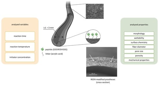
2.1. Fibrous Material Fabrication

Polyurethane (ChronoFlex C75A, AdvanSorce Biomaterials, Wilmington, MA, USA) nanofibrous materials were produced in the solution blow spinning process (SBS), described in detail elsewhere [25]. Polymer solution was prepared by mixing a polymer overnight in concentrations of 2% w/w in 1,1,1,3,3,3-hexafluoro-2-propanol (>99.0%, TCI Chemicals, Fukaya, Japan). A polyurethane solution was supplied through the inner nozzle of the concentric nozzles system in the solution blow spinning (SBS) apparatus with a constant flow rate of 30 mL∙h−1 to produce nanofibrous materials. Simultaneously, the airstream was supplied through the outer nozzle of the SBS nozzles system with a pressure of 0.1 MPa. Fibers were produced by shear-drag elongation of the polymer solution by the stream of air on the distance between the nozzles system and the collector’s surface, so-called working distance. For flat nanofibrous mats production, the rotating cylinder with a diameter of 12 mm was used as a collector (sample length: 120 mm; rotational speed: 3000 rpm; solution volume: 60 mL; production time: 2 h). The rotating cylinder with a diameter of 3 mm was used (sample length: 120 mm, rotational speed: 3000 rpm, solution volume: 20 mL, production time: 40 min) to produce a small diameter vascular prosthesis. Samples were pulled off the collector and kept in ventilated containers overnight to ensure complete solvent evaporation.

2.2. Surface Modification of Flat Nanofibrous Mats

Cylindrical material obtained by the SBS technique were cut along the side and 10 mm diameter discs were cut out from the material. The sample discs were grafted with acrylic acid (AA) according to the following procedure: before the grafting reaction, samples were immersed in propan-2-ol solution (100% v/v) for 15 min. After the immersion, samples were washed with distilled water (5×), 15 min each time. Next, samples were immersed in a 0.4 M solution of HNO3 in distilled water. Two reaction temperatures were tested (25 °C and 35 °C). After reaching the set temperature, the grafting initiator (NH4)4Ce(SO4)4 (in different concentration: 0.01%, 0.05% and 0.1% w/v) and the grafted monomer, AA (1% v/v), were added to the solution. The mixture was left covered, stirring continuously for a given time. Three reaction times were tested: 0.5, 1 and 1.5 h. After completing the reaction, samples were rinsed with a 0.1% (w/v) sodium dodecyl sulfate (SDS) solution for about 1 min, then rinsed three times with distilled water and dried in an incubator at 37 °C. After the modification process, surface morphology was analyzed and the fiber diameter distribution was determined (as described in Section 2.3.1). All testes process parameters with corresponding materials variants are presented in Table 1.

2.3. Characterization of Modified Nanofibrous Mats

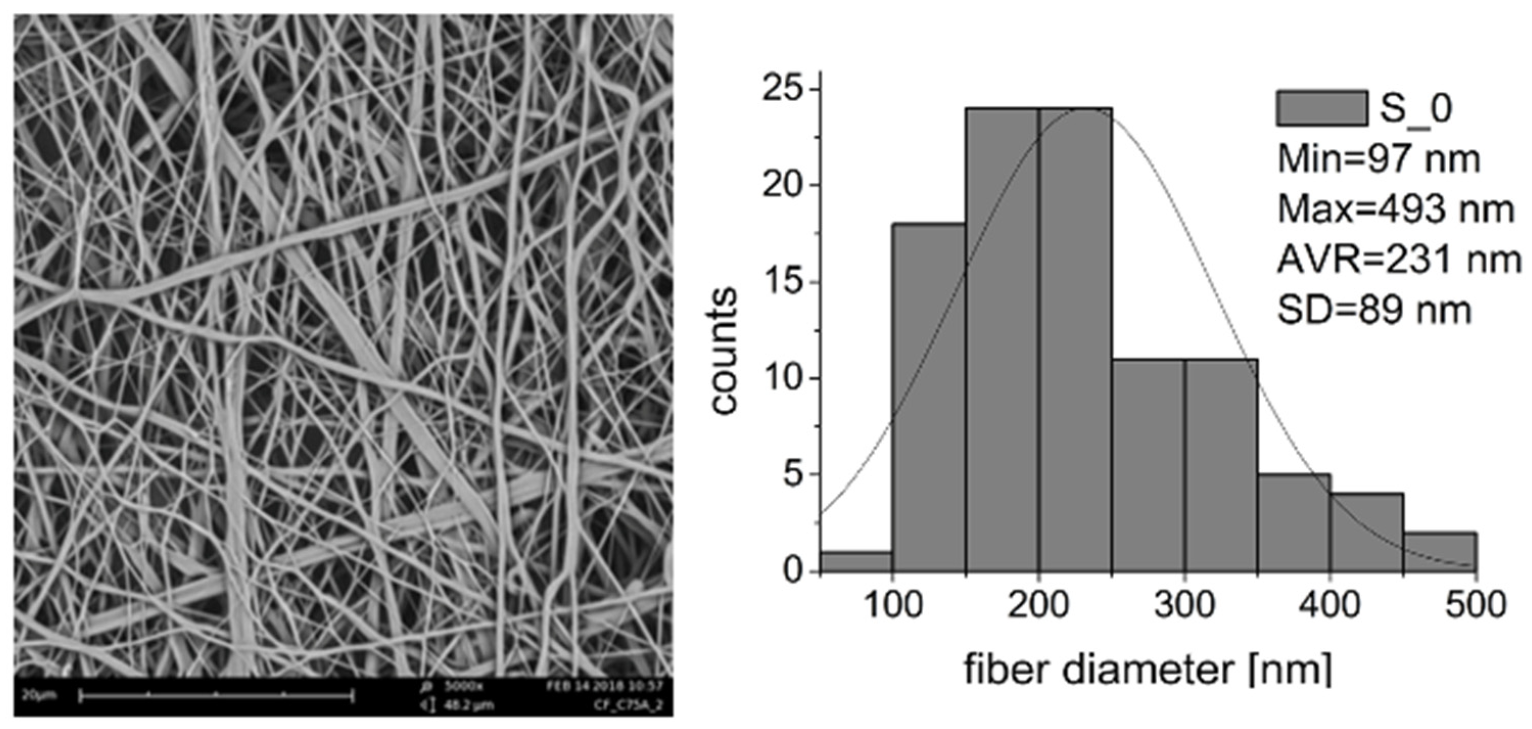
2.3.1. Fiber Morphology, Fiber Diameter and Pore Size

Materials were analyzed using scanning electron microscopy (SEM, Phenom G1, Phenom World, Eindhoven, The Netherlands). Samples were coated with a 15 nm layer of gold/palladium alloy (80/20 at.%) using a sputter coater (K550 Emitech, Quorum Technologies, Lewes, UK). Ten randomly selected spots were photographed with 5000× magnification and the images were used for the analysis of fiber diameter, pore size and fibrous material morphology. All measurements were performed using Fiji software [26]. Results are presented as a fiber size distribution (n = 100), average fiber diameter, standard deviation, minimum and maximum fiber diameter. Results of pore size measurements (n = 100) are presented as average pore size, standard deviation, minimum and maximum pore size.

2.3.2. Surface Wettability

Materials in the form of cylinders were cut to obtain flat mats. The internal surface (from the collector side) was subjected to wettability analysis. Samples were glued to the glass slide and a drop of distilled water (5 µL) was placed on a clean and dry surface. The contact angle was measured automatically using Krüss DSA 100 software; the measurement was performed in at least 3 randomly selected spots on analyzed material. The results of the measurements were expressed as means ± SD. The statistical significance of differences was analyzed using a single-factor analysis of variance (ANOVA) for p < 0.05 with post-hoc Tukey’s test (OriginPRO 2020b).

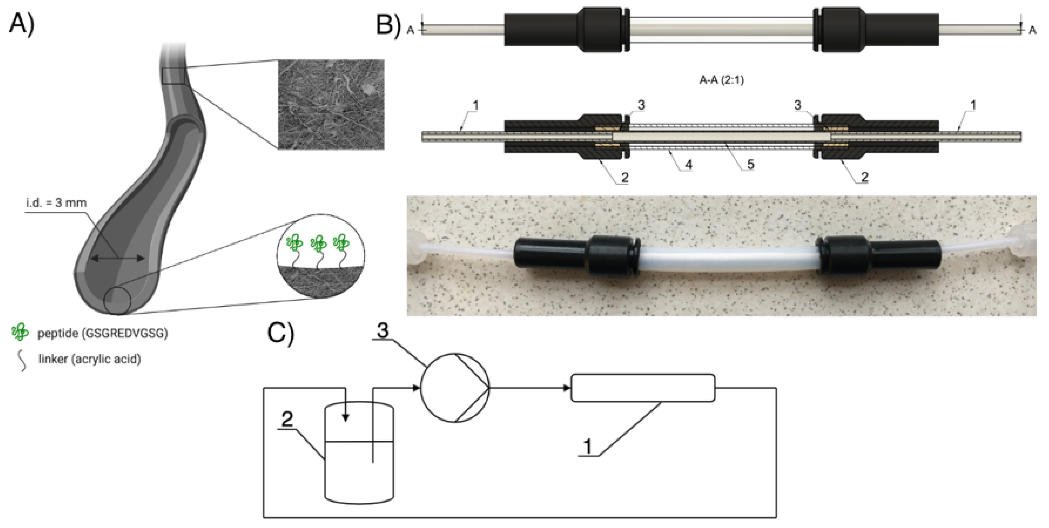
2.4. Surface Modification of Cylindrical Nanofibrous Prostheses in a Flow System

Modification Process

The modification process was carried out for selected process parameters using the flow system (Figure 1). As a base material, cylinder-shaped prostheses with a length of 5 cm and an internal diameter of 3 mm were used (Figure 1A). A photo of the modification chambers, together with prostheses placed inside, is shown in Figure 1B. The modification chamber was a part of a flow system schematically shown in Figure 1C. Only the scaffold’s internal surface was modified during the process, whereas the external surface was not in contact with the modifying solution. Prostheses were subjected to the multi-step modification process. At each step of the process, the modifying solution flowed through the prosthesis at a given flow rate for a specified time. First, prostheses were flushed with propan-2-ol for 3 min and then washed with distilled water for 25 min. In the first step of the modification process, a modifying solution containing AA (1% v/v) and (NH4)4Ce(SO4)4 (0.01% w/v) flowed through the prosthesis. The reaction was carried out at 25 °C for 0.5 h. Next, a 0.1% (w/v) SDS solution flowed through the prosthesis for about 2 min and was followed with water for the next 10 min. Samples after the first step of modification were designated as PU_COOH.
In the second modification step, prostheses were filled with 0.05 M 2-(N-morpholino)ethanesulfonic acid (MES) buffer (pH = 6.0) and contacted with the solution for 1 h at 25 °C. Next, two modifying solutions flowed through samples. Firstly, MES buffer (pH = 6.0) with N-hydroxysulfosuccinimide sodium salt (sulfo-NHS, 5 mM) and N-(3-Dimethylaminopropyl)-N′-ethylcarbodiimide hydrochloride (EDC, 2 mM) for 15 min. Secondly, REDV solution (5 mM in phosphate buffer, pH = 8) for 24 h. Samples after the second modification step were designated as PU_REDV.
Simultaneously, the material modified under the same conditions (1% AA, 25 °C, 0.5 h, 5 mM REDV) but without the use of cerium salts, were prepared.
At each stage of the modification, the modifying solutions flowed through the prosthesis at an equal flow rate. After the modification process, samples were incubated in phosphate buffer, pH = 9 and air-dried.

2.5. Characterization of Cylindrical Prostheses Modified in a Flow System

2.5.1. Fiber Morphology, Fiber Diameter and Pore Size

The parameters were measured and calculated as described in Section 2.3.1. For every sample, both ends of the prosthesis were characterized separately. Four SEM images were taken for every analyzed area. The thickness of the prosthesis’ wall before and after modification was measured using SEM cross-section images (n = 3).

2.5.2. Surface Wettability

Surface wettability was measured and calculated as described in Section 2.3.2. For every sample, both ends of the prosthesis were characterized separately.

2.5.3. Porosity Measurements

Porosity measurements were conducted using gravimetric analysis [27]. Each prosthesis was cut into 20 mm in length and weighed. After that, the wall thickness of the sample was measured using SEM. The apparent density of each sample was calculated using the following formula:
ρ a p p   [ g cm 3 ] =   m s c a f f o l d   [ g ] V s c a f f o l d   [ cm 3 ] =   m s c a f f o l d   [ g ] π δ L ( d i n + δ )   [ cm 3 ] ,
where:
ρapp—sample apparent density [g/cm3];
mscaffold—sample mass [g];
Vscaffold—sample volume [cm3];
δ—sample wall thickness [cm];
din—sample inner diameter [cm];
L—sample length [cm].
By comparison of apparent density calculated for each scaffold and known density of the polymer (ρp = 1.2 g/cm3), the porosity (η) of each scaffold can be calculated using the following formula:
η ( % ) =   ( 1 ρ a p p ρ p ) × 100 % .
Results are presented as average porosity (n = 5) ± standard deviation.

2.5.4. Mechanical Testing

Cylindrical samples (3 mm inner diameter, 50 mm length) of nanofibrous prostheses materials underwent a uniaxial stretching test according to protocols established based on ASTM standards (Designation: D 882-02 and D 638-02a). The experiment was conducted using an Instron 3345 model with crosshead speed 5 mm∙min−1 at room temperature and humidity. Load-strain curves were measured, as were the maximum load and strain at rupture. It is emphasized that according to porosity measurements and SEM images, only a fraction of each sample thickness is occupied with fibers (1 − η), which implies that the applied load is supported by only such fraction of the sample’s thickness. This effect was accounted for in the data processing for maximum stress calculation. Ultimate tensile stress for porous sample (σpor) was determined using the formula:
σ p o r = F m a x A ( 1 η ) ,
where:
σpor—ultimate tensile stress for porous sample [Pa]
Fmax—maximum force acting on the sample [N]
A—cross-section area [m2]
η—sample porosity [-]
For each type of scaffold, results are presented as average values (n = 5) ± standard deviation.

2.5.5. Spectroscopic Analysis

Chemical analysis of the surface before and after each step of modification was performed by X-ray photoelectron spectroscopy (XPS). XPS analysis was performed using Scienta R4000. Spectra fitting and determination of atomic composition were realized with the CasaXPS software.

3. Results

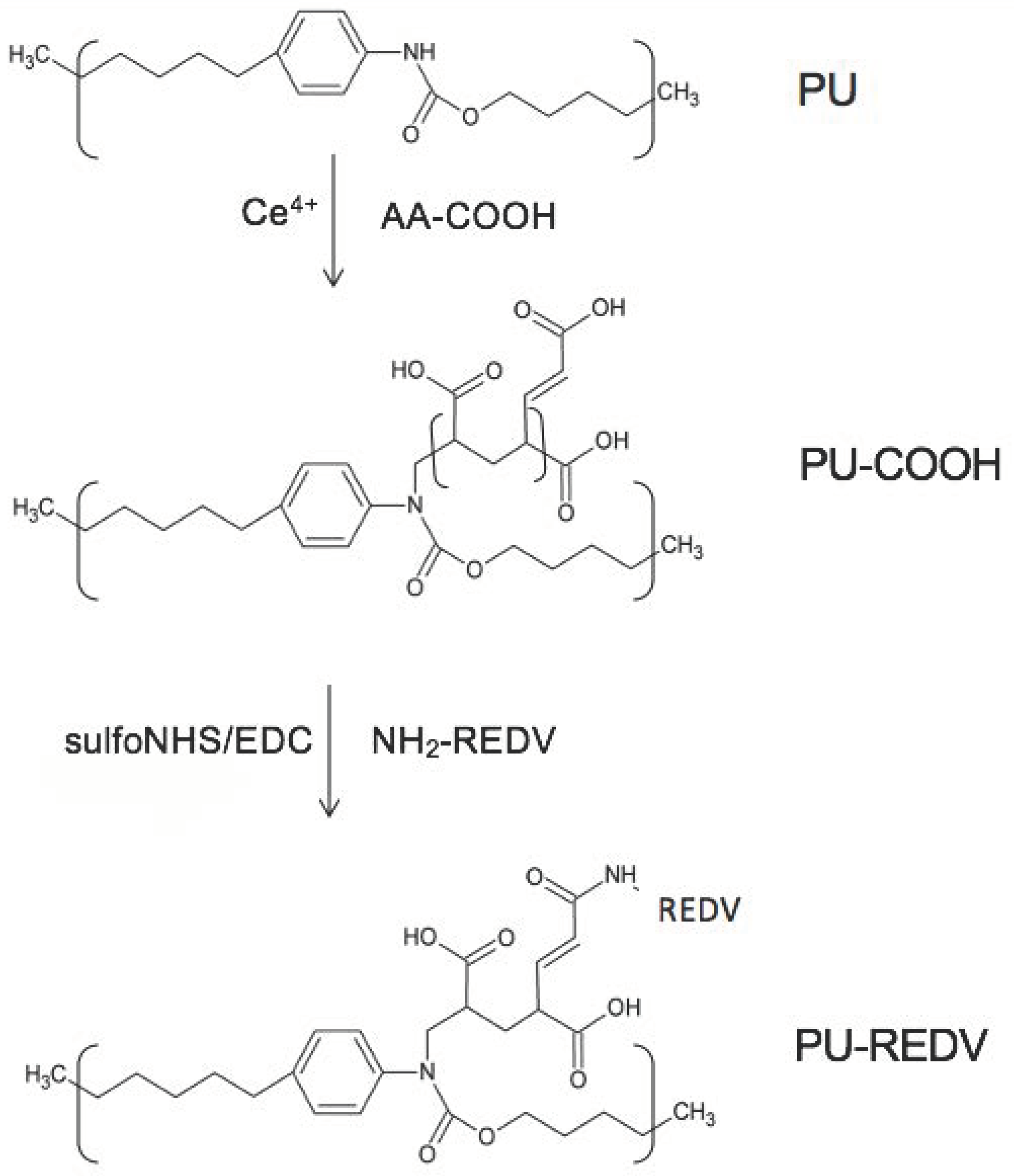
3.1. Mechanism of the Modification Process

The mechanism of the proposed two-step modification reaction (Figure 2) is described in detail elsewhere [24,28]. Briefly, in the first step, acrylic acid (AA) is bonded to the urethane group. A double bond present in AA chains reacts with radicals formed due to a reaction between cerium ions and urethane group. In the second step, carboxyl groups present on AA-grafted PU are activated with sulfo-NHS/EDC. Finally, the peptide is grafted to the surface, forming peptide bonds between the amine and carboxyl groups.

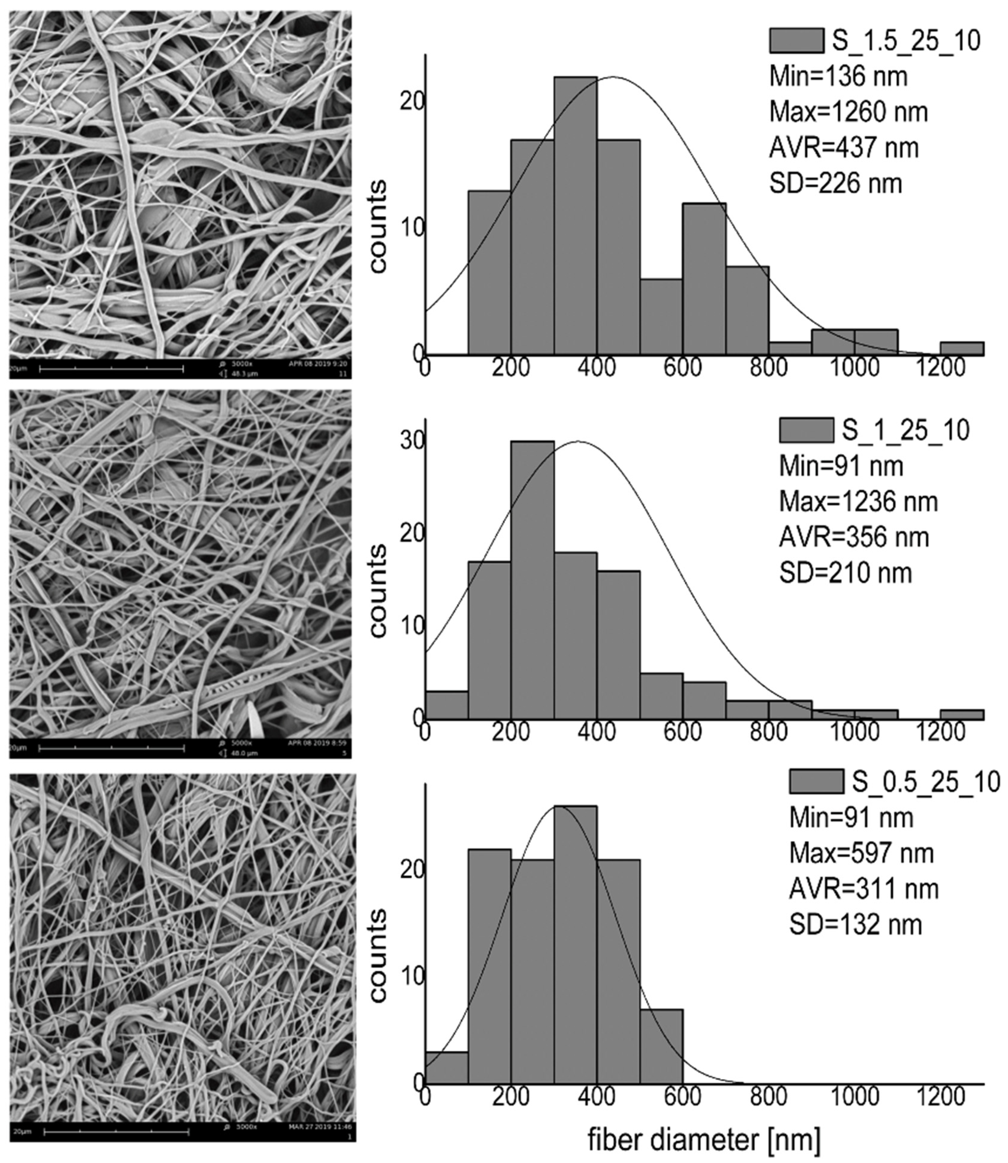
3.2. Modification of Nanofibrous Mats—The Influence of Process Parameters on the Fiber Morphology and Wettability

Figure 3 shows the morphology and diameter distribution of the non-modified nanofibrous mats. The average fiber diameter was 231 ± 89 nm. The fiber diameters ranged from 97 nm (minimum diameter) to 493 nm (maximum diameter).
Figure 4 presents the morphology of nanofibrous mats modified using different reaction times. All reactions were carried out at 25 °C with an initiator concentration of 0.01%. The histogram obtained for the material variant modified under the mildest conditions (S_0.5_25_10) slightly differed from the histogram for the non-modified nanofibrous mat. The average fiber diameter (S_0: 231 nm, S_0.5_25_10: 311 nm) and the maximum fiber diameter (S_0: 493 nm, S_0.5_25_10: 597 nm) are slightly increased. This increase is in line with expectations and is due to the attachment of AA to the fiber surface. Analysis of histograms of mats modified using different reaction times shows that this process parameter affected fiber diameters’ distribution. As the reaction time increases, there is an increase in both the average diameter (S_0.5_25_10: 311 nm, S_1_25_10: 356 nm, S_1.5_25_10: 437 nm) and the maximum fiber diameter (S_0.5_25_10: 597 nm, S_1_25_10: 1236 nm, S_1.5_25_10: 1260 nm). For longer reaction times: 1 h and 1.5 h (S_1_25_10 and S_1.5_25_10), microfibers with fiber diameter >1000 nm appear. A thorough analysis of the SEM images indicates that these fibers are composed of several nanofibers, connected due to the AA grafting. Simultaneously, the fibers’ surface structure is unaffected for all tested variants; no cracks or defects were noted.
Figure 5 shows nanofibrous mats’ morphology using different reaction times for reactions carried out at 35 °C, with an initiator concentration of 0.01% mg. Similarly, as in the mats modified at 25 °C, the diameters’ range increases with the reaction time increase. Also, as the reaction time increases, there is an increase in the average diameter (S_0.5_35_10: 514 nm, S_1_35_10: 550 nm, S_1.5_35_10: 672 nm). For longer reaction times (S_1_35_10 and S_1.5_35_10), microfibers with fiber diameter >1000 nm appear.
A comparison of suitable nanofibrous mats modified using different reaction temperatures indicates that this process parameter also affects the fibers’ morphology. The reaction carried out under higher temperature (35 °C) resulted in a wider range of fiber diameters. The values of fiber diameter were also higher at higher reaction temperatures. For example, for reaction carried out for the shortest time (t = 0.5 h) the values of average fiber diameter were: 311 nm (S_0.5_25_10) and 514 nm (S_0.5_35_10), the values of maximum fiber diameters were: 597 nm (S_0.5_25_10) and 885 nm (S_0.5_35_10). At the same time, it is worth noting that the higher tested temperatures harmed individual fibers’ structure. SEM images show fiber cracks and some additional structures (“beads”) attached to the fibers modified under 35 °C (Figure 5, marked with arrows).
Figure 6 shows the characteristics of nanofibrous mats modified with higher concentrations of a polymerization initiator. At the initiator concentration of 0.05% (S_0.5_25_50), single beads were formed on the fiber structure, which could be caused by excessive AA polymerization on the fiber surface. The average fiber diameter was 556 nm; the maximum fiber diameter was 1624 nm. In the case of the highest tested initiator concentration (S_0.5_25_100), the fibers underwent severe deformation (Figure 5, marked with arrows), many microfibers were formed from interconnected nanofibers. Both the average fiber diameter and the maximum fiber diameter were higher compared to S_0.5_25_50 (AVR = 634 nm, Max = 1982 nm). Numerous beads attached to the fibers’ surface were also visible (Figure 5, marked with arrows).
The results of the contact angle analysis for all tested variants are presented in Table 2. The results show that wettability increased after modification for each tested variant. The decrease in contact angle was expected, indicating the successful attachment of the hydrophilic AA molecule. The differences between the contact angle (CA) values for each variant were slight, so the modification process parameters’ impact on surface wettability could not be defined.
Based on the above-presented results, the variant S_0.5_25_10 (reaction time: 0.5 h, reaction temperature 25 °C, initiator concentration: 0.01% w/v) was selected for further studies.

3.3. Modification of Cylindrical Nanofibrous Prostheses in a Flow System

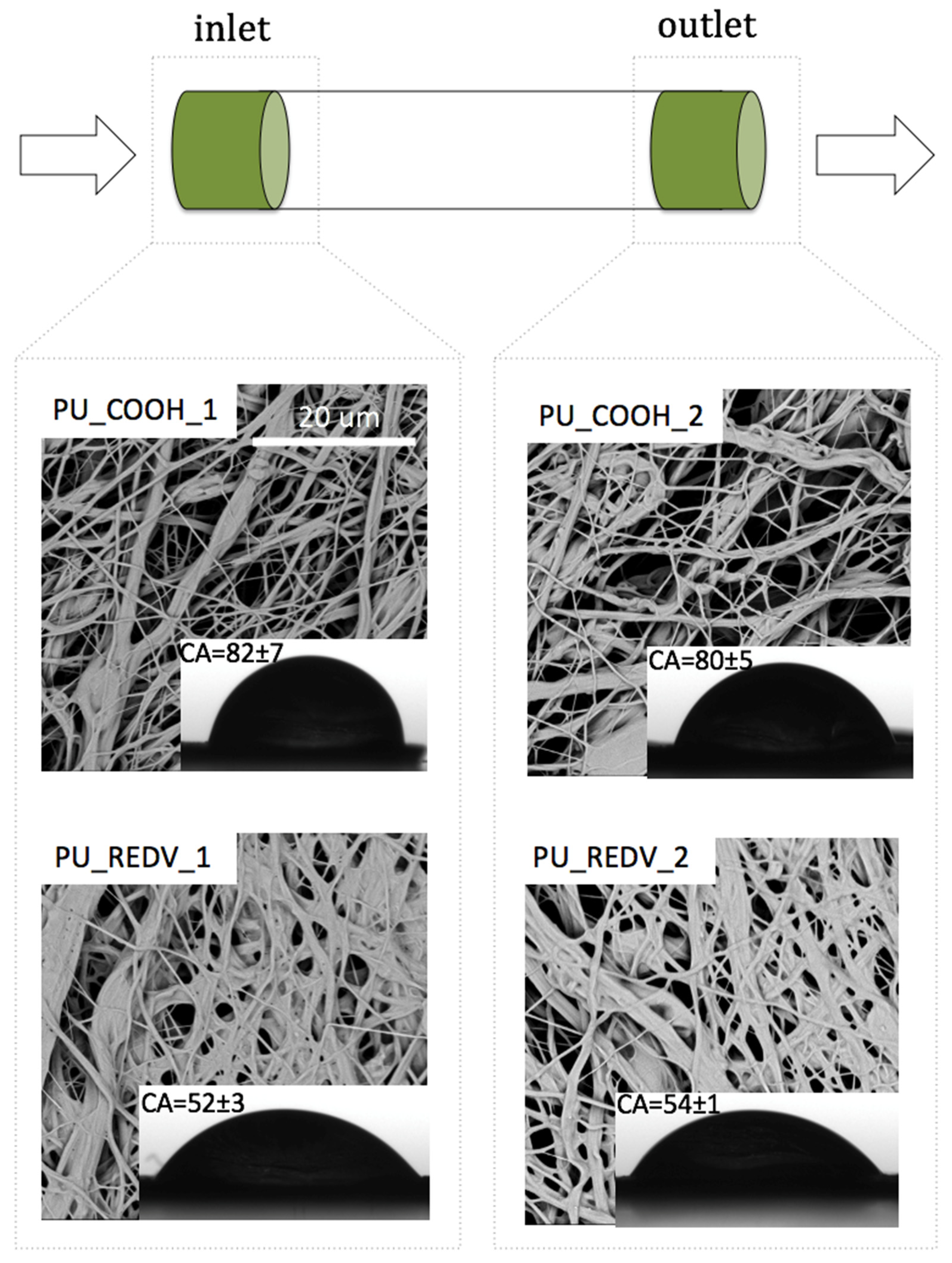
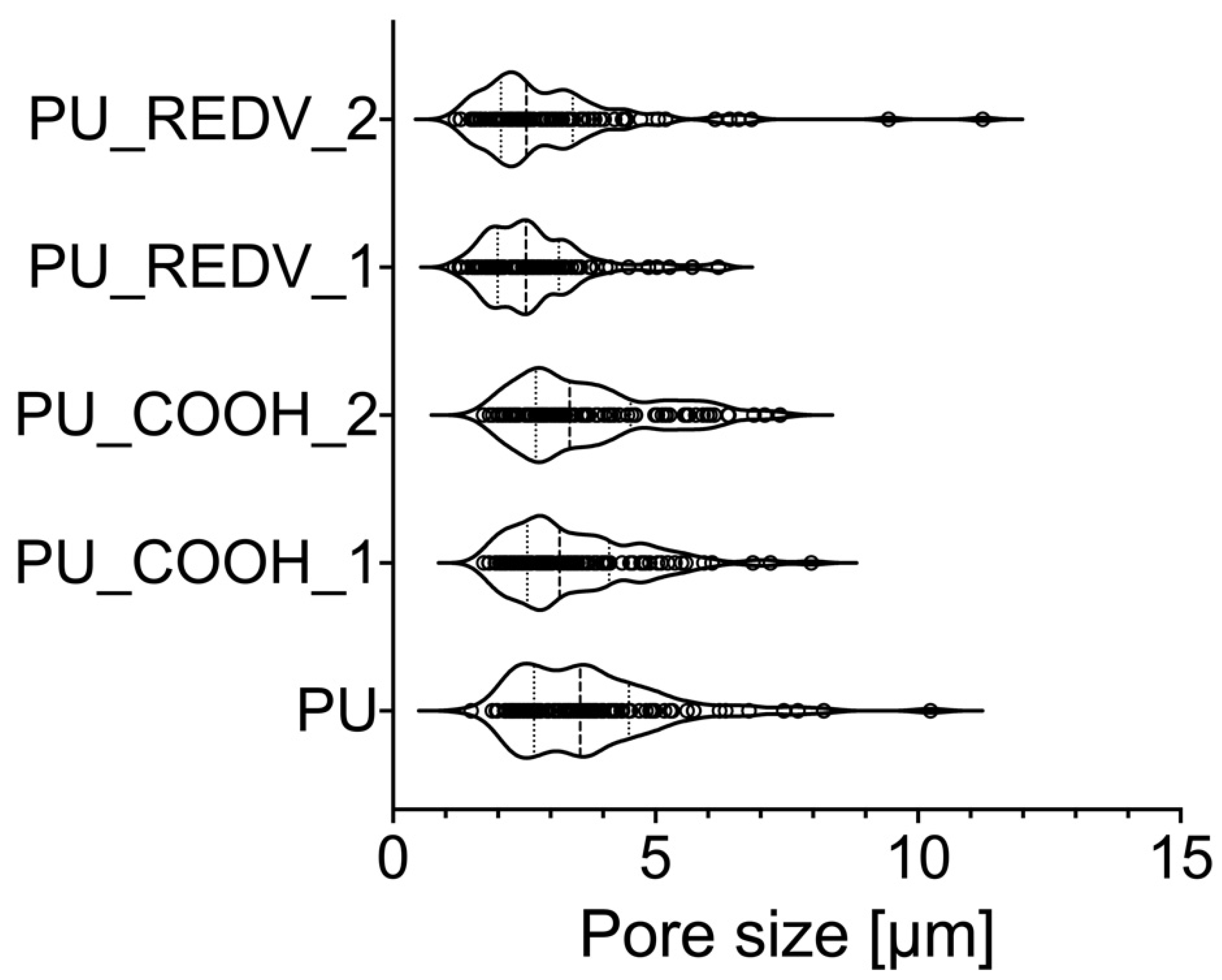
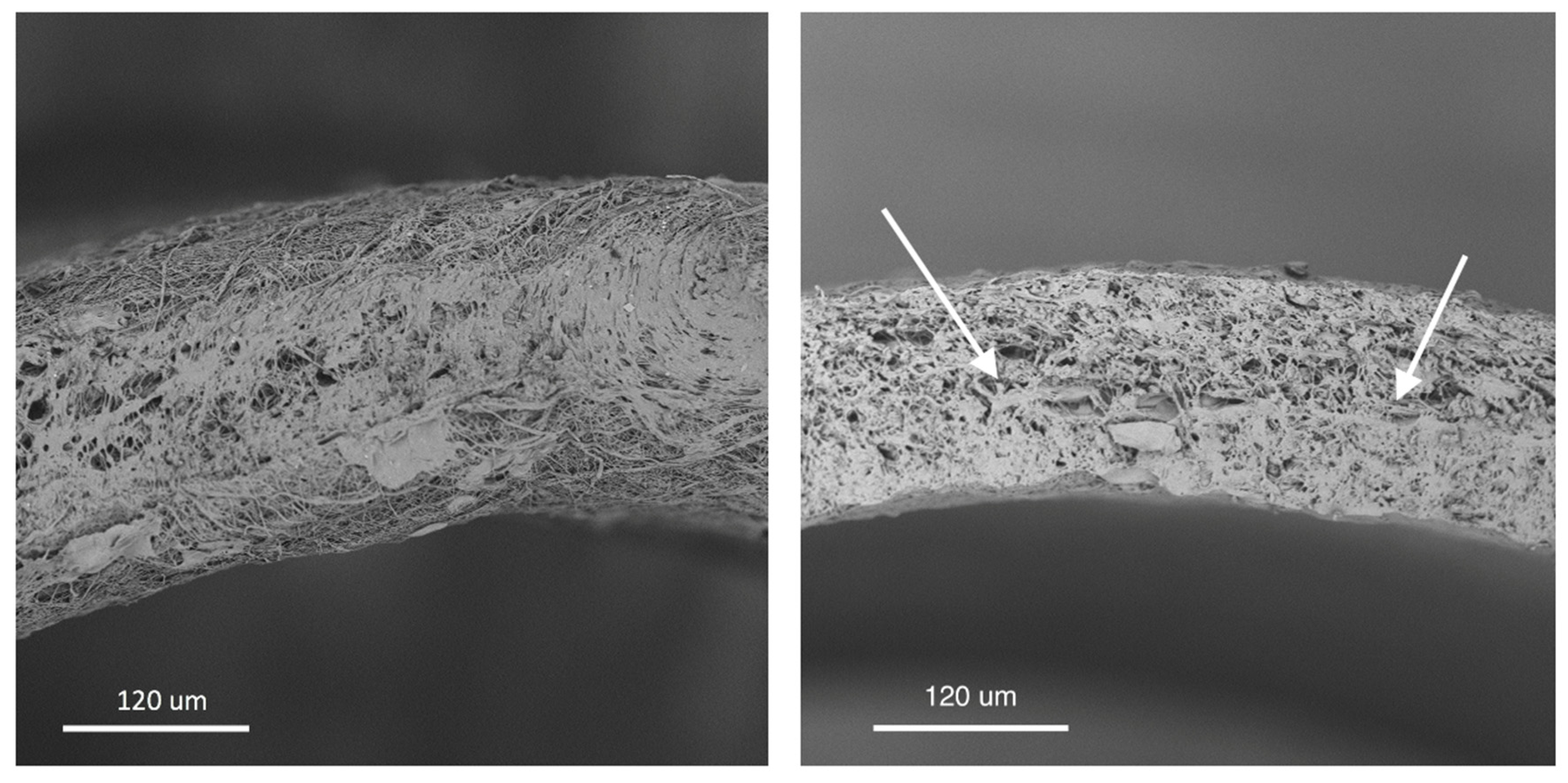
3.3.1. Morphology, Wettability, Pore Size and Porosity

Figure 7 shows the morphology of the cylindrical nanofibrous prosthesis modified in a flow system. It can be seen that after the first step of modification (AA grafting), the morphology of the modified mat was similar to the non-modified material. AA grafting did not cause considerable changes in nanofibers’ structure; no fiber defects were noticed. Surface wettability analysis confirmed the successful AA attachment. As expected, the contact angle value significantly (p < 0.05) decreased compared to the unmodified material (CA = 134 ± 1°). Simultaneously, there were no significant changes (p > 0.05) in surface wettability, depending on the analysis place. The contact angle values were 82 ± 7° and 80 ± 5° for prosthesis’ inlet (PU_COOH_1) and outlet (PU_COOH_2), respectively.
The second step of modification (REDV attachment) resulted in a change in the fiber’s morphology—the film-like structure was formed between the fibers (Figure 7). This phenomenon was observed in both the inlet and the outlet area of the prosthesis. As expected, attachment of the peptide resulted in a further reduction of contact angle values. Simultaneously, there were no significant changes (p > 0.05) in surface wettability, depending on the analysis place. The contact angle values were 52 ± 3° and 54 ± 1° for the inlet (PU_REDV_1) and outlet (PU_REDV_2) area, respectively.
Surface wettability of the material modified under the same process conditions (1% AA, 25 °C, 0.5 h) but without cerium salt, was also examined. This experiment was performed to estimate the amount of acrylic acid that physically attach to the fibers without chemical bonds. The contact angle value measured for that surface was 103 ± 2°. The value was significantly (p < 0.05) lower compared to unmodified material (CA = 134 ± 1°), which shows that part of the AA is physically deposited on fibers from the solution. However, this value was still higher than the values obtained for chemically grafted surface (CA = 80 ± 5°, p > 0.05). The contact angle value obtained for material modified under the same process conditions (1% AA, 25 °C, 0.5 h, without the addition of cerium salt) followed with incubation with 5mM REDV resulted in a surface contact angle value equal to 95 ± 5° (p < 0.05 vs. PU_REDV_1). This value was similar to that obtained after the first step of modification (physical adsorption of AA) and significantly higher than the value measured for material chemically grafted with AA and REDV. Therefore, we can conclude that the physical bonding of AA and REDV, without cerium salts’ participation, occurs only to a small extent. The contact angle values obtained for analogous surfaces modified with cerium salt was significantly lower (52 ± 3°, p < 0.05).
The nanofibrous prostheses’ basic physical parameters before and after the modification process are presented in Table 3. Analysis of fiber diameters showed that the average diameter of the fiber increased after the modification process. This is a result consistent with microscopic observation. Simultaneously, no considerable differences in the fiber’s average diameter between prosthesis’ inlet (318 ± 99 nm) and outlet (311 ± 110 nm) have not been demonstrated. As expected, the minimum and maximum diameter of the fiber has also increased after the REDV attachment. This value was 493 nm for a non-modified prosthesis and, after modification, increased to 640 nm and 840 nm for the prosthesis’ inlet and outlet, respectively. A similar relationship was demonstrated with the minimum fiber diameter value. For non-modified prosthesis, this value was 97 nm. The REDV attachment increased the minimum fiber diameter to 121 nm and 164 nm, respectively, for the prosthesis’ inlet and outlet.
Reverse dependency was shown for the average size of pores (Figure 8). For the non-modified prosthesis, this value was 3.8 ± 1.5 μm, with the minimum pore size of 1.5 μm and the maximum pore size of 10.2 μm. After AA grafting, those values did not significantly change and the distribution of pore size was close to the one for PU. After the REDV attachment, the average size decreased to 2.7 ± 1.0 μm and 3.0 ± 1.6 μm for the prothesis’ inlet (PU_REDV_1) and outlet (PU_REDV_2), respectively. The maximum pore size was 6.2 μm in the inlet area and 11.2 μm in the outlet area. However, it is worth noting that in the case of PU_REDV_2 during the analysis, only two large pores (>9 μm) were detected. The majority of pores were smaller compared to the non-modified material. The minimum size of pores has slightly changed. It equaled 1.2 μm for PU_REDV_1 and PU_REDV_2.
The modification process resulted in a slight decrease in the prosthesis’ porosity. The measured porosity values were 53.5 ± 2.9% and 48.4 ± 8.6% for non-modified prosthesis and REDV-modified prosthesis, respectively. Figure 9 presents the cross-section of the prosthesis after inner surface modification. It can be clearly seen that the modification process changes the porosity of the internal surface. At the same time, it can be seen that the modification has taken place to a certain depth, approximately 1/3 of the thickness of the prosthesis’ wall. Arrows indicate the boundary between the modified structure and the unchanged structure. The thickness of the prosthesis wall before the modification process was 271 ± 27 μm. The modification process resulted in the thickness reduction—the value after modification decreased to 174 ± 34 μm.

3.3.2. Mechanical Properties

The mechanical properties of the prostheses before and after the REDV modification process are presented in Table 2. The average Young’s modulus for modified prostheses equaled 4.0 ± 0.4 MPa. The value was about twice higher than the non-modified ones (1.8 ± 0.3 MPa), which means the prostheses after modification are slightly stiffer. The average tensile stress for modified prostheses was 12.7 ± 1.7 MPa and about six times higher than the unmodified ones (2.1 ± 0.3 MPa). The average maximum elongation at break for modified prostheses was 2.5 ± 0.5 mm/mm—it was about 1.5× increased compared to the non-modified materials (1.5 ± 0.1 mm/mm).

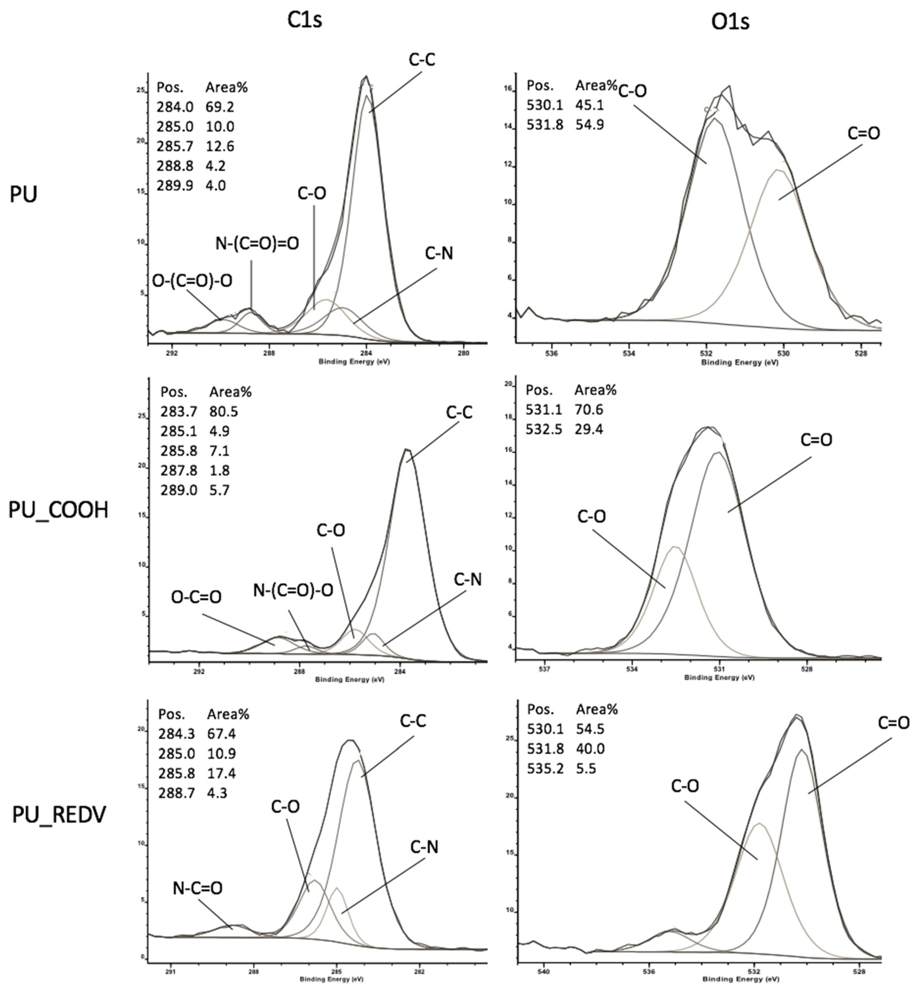
3.3.3. Spectroscopic Analysis

XPS analysis enabled monitoring of the subsequent steps of the modification reaction. The assumed chemistry of the reaction is shown in Figure 2. For the exact mechanism of grafting acrylic acid to polyurethane, please refer to our previous paper [24]. XPS spectra of C1s and O1s are presented in Figure 10.
In the unmodified surface (PU) case, the C1s spectrum can be curve-fitted into five peaks. The four peaks with BEs of about 284.0, 285.0, 285.7 and 288.8 eV are attributable to C–H, C–N, C–O and O–(C=O)–N species, which is following data presented for polyurethanes [29]. The fifth peak with a high BE of 289.9 eV corresponds to the carbonate group (O-(C=O)-O) [30] of ChronoFlex, which is a carbonate-based polyurethane. After acrylic acid grafting (PU_COOH), the intensity of peaks attributed to C-N, C-O and N-C=O decreased. Also, the peak associated with the carbonate group (289.9 eV) disappeared. A new peak with BE of 289.0 eV, which is attributed to carboxyl groups (O-(C=O)) [28,29,31], appeared. C1s spectrum of surface bonded with REDV (PU_REDV) can be fitted into four peaks. There are peaks with BEs of about 284.3, 285.0, 285.8 and 288.7 eV, attributed to C–H, C–N, C–O and N-C=O. The presence of a 288.7 eV peak attributed to the amide group [19,31] proves the successful introduction of REDV.
The O1s spectrum for PU was separated into two components corresponding to the binding energy ~530 eV (carboxylic oxygen) and ~532 eV (single-bonded oxygen). In the case of PU_COOH also two peaks appeared, however, the intensity of peaks corresponded with carboxylic oxygen increased. The third peak with high BE (~535.2 eV) appeared in the O1s spectrum of PU-REDV, attributed to adsorbed water [19,30].

4. Discussion

The presented research aimed to design the modification process for the internal surface of cylindrical nanofibrous prostheses. The process is intended to improve bio- and hemocompatibility by increasing wettability and introducing endothelial cell-selective peptide to the surface. Simultaneously, the process should not cause a severe change in the nanofibers’ initial morphology.
A chemical modification method was proposed, the mechanism of which was presented and described previously [24,27]. Briefly, this method consists of two steps, in which the hydrophilic linker (AA) is attached in the first step and the peptide molecule (REDV) is chemically bonded in the next step.
In previous works, we presented the results of surface modification of solid polyurethane films. The reaction conditions considered by us as optimal (resulting in the highest concentration of generated COOH groups) proved to be unequal for modifying fibrous materials. The modification carried out at high temperatures (35 °C), using longer reaction time (1.5 h) and a higher monomer concentration (5% AA), led to degradation of the fiber structure. Numerous cracks appeared, many additional structures (“beads”) attached to the fibers were visible.
The scope of the presented work included optimizing the conditions for conducting the modification process for fibrous material. The influence of reaction temperature, reaction time and the polymerization initiator’s concentration morphology of the modified fibers was investigated. It was shown that all of the analyzed parameters had a substantial impact on the fibers’ morphology.
The range of fiber diameters increased with increasing both the process temperature and the reaction time. It was observed that the grafting reaction carried out at a higher temperature (35 °C) resulted in fibers with a larger average fiber diameter compared to fibers modified at a lower temperature (25 °C). Also, the minimum and maximum fiber diameter values were higher for reaction carried out at 35 °C. A similar effect was observed with the increase in the reaction time. For longer reaction time (1 h and 1.5 h), values of average fiber diameter as well as minimum and maximum diameters of fibers were higher compared to those modified for a shorter time (0.5 h).
This result indicates a higher efficiency of the grafting process at a higher temperature and longer reaction times—more AA was bound to the surface of fibers causing the increase in fiber diameters. On the other hand, the fibers’ morphology analysis shows that both higher temperature and longer reaction time harm their structure. Analysis of SEM images has shown that elevated temperatures, especially in combination with the longest reaction time, resulted in unfavorable fiber morphology changes, including fiber ruptures.
Thus, we found as optimal the reaction carried out at a temperature of 25 °C, during 0.5 h, with an initiator concentration of 0.01%. Those conditions resulted in no changes in the morphology and distribution of fiber diameters. Simultaneously, they allow conducting effective modification—the process carried out in these conditions increased surface wettability.
For the selected parameters, the modification process was carried out for the fibrous prosthesis in the form of a cylinder (internal diameter = 3 mm). The modification process was performed using the flow system. As a final product, prosthesis with a peptide-modified internal surface was obtained. The so-prepared material was subjected to an analysis of physicochemical properties, distinguishing the inlet (beginning of the prosthesis) and the outlet (end of the prosthesis) areas.
Analysis of morphology and wettability after each step of the process showed that the process was effective over the prosthesis length. No considerable difference was shown in the fiber diameter and the contact angle value between the inlet and the outlet area of the REDV-modified protheses. As expected, the introduction of REDV to the surface resulted in a significant decrease in the water contact angle. A similar effect was obtained when modifying fibers with other biomolecules, that is, heparin and VEGF [32]. Wettability is an important parameter that strongly affects processes such as cell adhesion and cell activation. In the case of vascular prostheses, an increase of hydrophilicity is associated with the decrease in blood plasma protein adsorption and, as a result, an increase in surface hemocompatibility.
Subsequent steps of the modification have been confirmed by XPS analysis. Grafting of acrylic acid is evidenced by a peak with the binding energy of about 289 eV, characteristic for the carboxyl group. The peptide binding is confirmed by the peak with BE of 288 eV, characteristic for the amine group.
SEM image analysis showed that the introduction of peptide reduced the average pore size. A similar phenomenon was observed in other works [32,33]. This result confirmed the effective attachment of modifying factors. Simultaneously, despite the increase in the fibers’ diameter, the diameter range is <1 μm. This is particularly important in the context of the potential use of the presented material as vascular prostheses. According to the results presented by other authors, the range of fiber diameters <1 μm is optimal for endothelial cells’ growth. Ju et al. showed that endothelial cells growing on nanofibers (approx. fiber diameter = 270 nm) presented numerous actin fibers and formed stronger focal adhesion contacts than those growing on microfiber [3]. It has also been shown that scaffolds composed of thin fibers (diameter <1 μm) triggered very low coagulation and almost no platelets adhered compared to those with a bigger fiber diameter (2–3 μm) [3].
In fibrous materials, the fiber diameter is a value closely related to the pore size. The presented material is characterized by an average diameter of pores equal to approximately 3 μm. This is an appropriate value for the growth of endothelial cells. Pore size is also an essential parameter for the effectiveness of vascular prosthesis. Studies show that smaller pore sizes are preferred for the internal surface, enabling the formation of a monolayer along the surface, at the same time limiting the migration of cells deep inside the structure [22].
The performed modification did not substantially change the porosity of the prosthesis. Despite the decrease in pore size after modification, the prosthesis’ total porosity has only slightly reduced. This is due to the limited depth of reagents penetration inside the prosthesis wall. Cross-section analysis showed that the modification occurs at a depth equal to approximately 1/3 of the prosthesis wall’s total thickness. Maintaining adequate porosity along the entire thickness of the wall is essential in the context of the smooth muscle cell penetration and the formation of new blood vessels [4].
With frequently used polytetrafluoroethylene (PTFE) prostheses, high prostheses stiffness remains the problem. Young’s modulus for these materials is in the range of 40–60 MPa [34], while this value for the human coronary artery is about 1 MPa [35]. Young’s modulus received for the REDV-modified prostheses was close to that value and was approximately 4 MPa. Simultaneously, despite the increase in Young’s modulus value, the prosthesis after modification remains flexible and durable- the modification increases tensile strength and maximum elongation value.

5. Conclusions

A modification process that enables introducing a peptide to the internal surface of cylindrical nanofibers prostheses is proposed. The process is versatile in terms of the introduced molecule—other peptides and proteins can be integrated to the surface.
The proposed modification did not change the initial morphological properties of the prosthesis. The peptide-modified surface is characterized by the presence of nanofibers and the pores with the average size <10 μm, which should promote the development of cell monolayer. Simultaneously, the modified prostheses maintain relatively high total porosity, which could enhance the infiltration of smooth muscle cells and transport of a substance across the prosthesis’ wall. The introduced modification increases Young’s modulus value but it is still a value similar to the one characterizing human coronary vessels.
The authors are aware that further biological analyzes, examining the response of blood components and endothelial cells, are necessary to assess the proposed modification’s effectiveness. These studies are the next stage of the presented work.

Author Contributions

B.A.B.-R.: conceptualization, methodology, formal analysis, resources, writing—original draft, visualization, supervision, project administration, funding acquisition; A.K.: methodology, investigation, writing—review & editing; M.W.: methodology, investigation, writing—review & editing; Z.P.: investigation. All authors have read and agreed to the published version of the manuscript.

Funding

The research was funded from the National Centre for Research and Development in the frame of Project Contract No. LIDER/18/0104/L-8/16/NCBR/2017.

Conflicts of Interest

The authors declare no conflict of interest. The funders had no role in the design of the study; in the collection, analyzes, or interpretation of data; in the writing of the manuscript, or in the decision to publish the results.

References

  1. Xue, L.; Greisler, H.P. Biomaterials in the development and future of vascular grafts. J. Vasc. Surg. 2003, 37, 472–480. [Google Scholar] [CrossRef] [PubMed] [Green Version]
  2. Taggart, D.P. Current status of arterial grafts for coronary artery bypass grafting. Ann. Cardiothorac. Surg. 2013, 2, 427–430. [Google Scholar] [PubMed]
  3. Ju, Y.M.; Choi, J.S.; Atala, A.; Yoo, J.J.; Lee, S.J. Bilayered scaffold for engineering cellularized blood vessels. Biomaterials 2010, 31, 4313–4321. [Google Scholar] [CrossRef] [PubMed]
  4. Milleret, V.; Hefti, T.; Hall, H.; Vogel, V.; Eberli, D. Influence of the fiber diameter and surface roughness of electrospun vascular grafts on blood activation. Acta Biomater. 2012, 8, 4349–4356. [Google Scholar] [CrossRef] [Green Version]
  5. Goins, A.; Webb, A.R.; Allen, J.B. Multi-layer approaches to scaffold-based small diameter vessel engineering: A review. Mater. Sci. Eng. C 2019, 97, 896–912. [Google Scholar] [CrossRef]
  6. Nakielski, P.; Pierini, F. Blood interactions with nano-and microfibers: Recent advances, challenges and applications in nano- and microfibrous hemostatic agents. Acta Biomater. 2019, 84, 63–76. [Google Scholar] [CrossRef]
  7. Hu, J.J.; Chao, W.C.; Lee, P.Y.; Huang, C.H. Construction and characterization of an electrospun tubular scaffold for small-diameter tissue-engineered vascular grafts: A scaffold membrane approach. J. Mech. Behav. Biomed. Mater. 2012, 13, 140–155. [Google Scholar] [CrossRef]
  8. Van Wachem, P.B.; Schakenraad, J.M.; Feijen, J.; Beugeling, T.; van Aken, W.G.; Blaauw, E.H.; Nieuwenhuis, P.; Molenaar, I. Adhesion and spreading of cultured endothelial cells on modified and unmodified poly (ethylene terephthalate): A morphological study. Biomaterials 1989, 10, 532–539. [Google Scholar] [CrossRef] [Green Version]
  9. Dubey, G.; Mequanint, K. Conjugation of fibronectin onto three-dimensional porous scaffolds for vascular tissue engineering applications. Acta Biomater. 2011, 7, 1114–1125. [Google Scholar] [CrossRef]
  10. Zhang, Y.; Chai, C.; Jiang, X.S.; Teoh, S.H.; Leong, K.W. Fibronectin immobilized by covalent conjugation or physical adsorption shows different bioactivity on aminated-PET. Mater. Sci. Eng. C 2007, 27, 213–219. [Google Scholar] [CrossRef]
  11. Dejana, E.; Lampugnani, M.G.; Giorgi, M.; Gaboli, M.; Marchisio, P.C. Fibrinogen induces endothelial cell adhesion and spreading via the release of endogenous matrix proteins and the recruitment of more than one integrin receptor. Blood 1990, 75, 1509–1517. [Google Scholar] [CrossRef] [PubMed] [Green Version]
  12. Browning, M.B.; Dempsey, D.; Guiza, V.; Becerra, S.; Rivera, J.; Russell, B.; Höök, M.; Clubb, F.; Miller, M.; Fossum, T.; et al. Multilayer vascular grafts based on collagen-mimetic proteins. Acta Biomater. 2012, 8, 1010–1021. [Google Scholar] [CrossRef] [PubMed]
  13. Lin, Y.S.; Wang, S.S.; Chung, T.W.; Wang, Y.H.; Chiou, S.H.; Hsu, J.J.; Chou, N.-K.; Hsieh, K.-H.; Chu, S.-H. Growth of endothelial cells on different concentrations of Gly-Arg-Gly-Asp photochemically grafted in polyethylene glycol modified polyurethane. Artif. Organs 2001, 25, 617–621. [Google Scholar] [CrossRef] [PubMed]
  14. Choi, W.S.; Bae, J.W.; Lim, H.R.; Joung, Y.K.; Park, J.-C.; Kwon, I.K.; Dong, P.K. RGD peptide-immobilized electrospun matrix of polyurethane for enhanced endothelial cell affinity. Biomed. Mater. 2008, 30, 44104. [Google Scholar] [CrossRef]
  15. Walluscheck, K.P.; Steinhoff, G.; Kelm, S.; Haverich, A. Improved endothelial cell attachment on ePTFE vascular grafts pretreated with synthetic RGD-containing peptides. Eur. J. Vasc. Endovasc. Surg. 1996, 12, 321–330. [Google Scholar] [CrossRef] [Green Version]
  16. Liu, J.C.; Heilshorn, S.C.; Tirrell, D.A. Comparative cell response to artificial extracellular matrix proteins containing the RGD and CS5 cell-binding domains. Biomacromolecules 2004, 5, 497–504. [Google Scholar] [CrossRef] [Green Version]
  17. Shin, H.; Jo, S.; Mikos, A.G. Biomimetic materials for tissue engineering. Biomaterials 2003, 24, 4353–4364. [Google Scholar] [CrossRef]
  18. Ji, Y.; Wei, Y.; Liu, X.; Wang, J.; Ren, K.; Ji, J. Zwitterionic polycarboxybetaine coating functionalized with REDV peptide to improve selectivity for endothelial cells. J. Biomed. Mater. Res. A 2012, 100, 1387–1397. [Google Scholar] [CrossRef]
  19. Castellanos, M.I.; Zenses, A.S.; Grau, A.; Rodríguez-Cabello, J.C.; Gil, F.J.; Manero, J.M.; Pegueroles, M. Biofunctionalization of REDV elastin-like recombinamers improves endothelialization on CoCr alloy surfaces for cardiovascular applications. Colloids Surf. B Biointerfaces 2015, 127, 22–32. [Google Scholar] [CrossRef] [Green Version]
  20. Wei, Y.; Ji, Y.; Xiao, L.; Lin, Q.; Ji, J. Different complex surfaces of polyethyleneglycol (PEG) and REDV ligand to enhance the endothelial cells selectivity over smooth muscle cells. Colloids Surf B Biointerfaces 2011, 84, 369–378. [Google Scholar] [CrossRef]
  21. Wang, W.; Guo, L.; Yu, Y.; Chen, Z.; Zhou, R.; Yuan, Z. Peptide REDV-modified polysaccharide hydrogel with endothelial cell selectivity for the promotion of angiogenesis. J. Biomed. Mater. Res. Part A 2015, 103, 1703–1712. [Google Scholar] [CrossRef] [PubMed]
  22. Massia, S.P.; Hubbell, J.A. Vascular endothelial cell adhesion and spreading promoted by the peptide REDV of the IIICS region of plasma fibronectin is mediated by integrin alpha 4 beta 1. J. Biol. Chem. 1992, 267, 14019–14026. [Google Scholar] [PubMed]
  23. Zhou, F.; Wen, M.; Zhou, P.; Zhao, Y.; Jia, X.; Fan, Y. Materials Science & Engineering C Electrospun membranes of PELCL/PCL-REDV loading with miRNA-126 for enhancement of vascular endothelial cell adhesion and proliferation. Mater. Sci. Eng. C 2018, 85, 37–46. [Google Scholar] [CrossRef]
  24. Butruk-Raszeja, B.A.; Kuźminska, A.; Ciach, T.; Adipurnama, I.; Yang, M.-C. Endothelial cell growth on polyurethane modified with acrylic acid and REDV peptide. Surf. Innov. 2019, 8, 1–17. [Google Scholar] [CrossRef]
  25. Wojasiński, M.; Pilarek, M.; Ciach, T. Comparative studies of electrospinning and solution blow spinning processes for the production of nanofibrous poly(L-lactic acid) materials for biomedical engineering. Pol. J. Chem. Technol. 2014, 16, 43–50. [Google Scholar] [CrossRef] [Green Version]
  26. Schindelin, J.; Arganda-Carreras, I.; Frise, E.; Kaynig, V.; Longair, M.; Pietzsch, T.; Preibisch, S.; Rueden, C.; Saalfeld, S.; Schmid, B.; et al. Fiji: An open-source platform for biological-image analysis. Nat. Methods 2012, 9, 676–682. [Google Scholar] [CrossRef] [PubMed] [Green Version]
  27. Butruk-Raszeja, B.A.; Trzaskowska, P.A.; Kuźminska, A.; Ciach, T. Polyurethane modification with acrylic acid by Ce(IV)-initiated graft polymerization. Open Chem. 2016, 14, 206–214. [Google Scholar] [CrossRef] [Green Version]
  28. Pranantyo, D.; Xu, L.Q.; Neoh, K.G.; Kang, E.T.; Yang, W.; Teo, S.L.M. Photoinduced anchoring and micropatterning of macroinitiators on polyurethane surfaces for graft polymerization of antifouling brush coatings. J. Mater. Chem. B 2014, 2, 398–408. [Google Scholar] [CrossRef]
  29. Qu, X.H.; Wu, Q.; Liang, J.; Qu, X.; Wang, S.G.; Chen, G.Q. Enhanced vascular-related cellular affinity on surface modified copolyesters of 3-hydroxybutyrate and 3-hydroxyhexanoate (PHBHHx). Biomaterials 2005, 26, 6991–7001. [Google Scholar] [CrossRef]
  30. Moulder, J.; Stickle, W.; Sobol, P.; Bomben, K. Handbook of X-ray Photoelectron Spectroscopy; Perkin-Elmer Corporation: Waltham, MA, USA, 1992. [Google Scholar]
  31. Gardner, S.D.; Singamsetty, C.S.K.; Booth, G.L.; He, G.R.; Pittman, C.U. Surface characterization of carbon fibers using angle-resolved XPS and ISS. Carbon 1995, 33, 587–595. [Google Scholar] [CrossRef]
  32. Davoudi, P.; Assadpour, S.; Derakhshan, M.A.; Ai, J.; Solouk, A.; Ghanbari, H. Biomimetic modification of polyurethane-based nanofibrous vascular grafts: A promising approach towards stable endothelial lining. Mater. Sci. Eng. C 2017, 80, 213–221. [Google Scholar] [CrossRef] [PubMed]
  33. Antonova, L.V.; Silnikov, V.N.; Sevostyanova, V.V.; Yuzhalin, A.E.; Koroleva, L.S.; Velikanova, E.A.; Mironov, A.V.; Godovikova, T.S.; Kutikhin, A.G.; Glushkova, T.V.; et al. Biocompatibility of small-diameter vascular grafts in different modes of RGD modification. Polymers 2019, 11, 174. [Google Scholar] [CrossRef] [PubMed] [Green Version]
  34. Wong, C.S.; Liu, X.; Xu, Z.; Lin, T.; Wang, X. Elastin and collagen enhances electrospun aligned polyurethane as scaffolds for vascular graft. J. Mater. Sci. Mater. Med. 2013, 24, 1865–1874. [Google Scholar] [CrossRef] [PubMed]
  35. Karimi, A.; Rahmati, S.M.; Sera, T.; Kudo, S.; Navidbakhsh, M. A combination of experimental and numerical methods to investigate the role of strain rate on the mechanical properties and collagen fiber orientations of the healthy and atherosclerotic human coronary arteries. Bioengineered 2017, 8, 154–170. [Google Scholar] [CrossRef] [Green Version]
Figure 1. The idea of prosthesis’ internal surface modification (A); scheme showing the prosthesis placed inside the modification chamber: 1—inlet/outlet, 2—connector, 3—seal, 4—Teflon tube, 5—prosthesis (B); scheme of the flow system used for modification: 1—modification chamber with a prosthesis, 2—fluid container, 3—peristaltic pump (C). Created with BioRender.com.
Coatings 10 01110 g001
Figure 2. Mechanism of a two-step reaction applied for the surface modification process.
Coatings 10 01110 g002
Figure 3. Morphology and fiber diameter distribution of non-modified nanofibrous mats.
Coatings 10 01110 g003
Figure 4. Morphology and fiber diameter distribution of nanofibrous mats modified at 25 °C for 1.5 h (top), 1 h (center), 0.5 h (bottom). For acronym definitions, see Table 1.
Coatings 10 01110 g004
Figure 5. Morphology and fiber diameter distribution of nanofibrous mats modified at 35 °C for 1.5 h (top), 1 h (center), 0.5 h (bottom). For acronym definitions, see Table 1.
Coatings 10 01110 g005
Figure 6. Morphology and fiber diameter distribution of nanofibrous mats modified at 25 °C for 0.5 h with different initiators’ concentrations: 0.05% (bottom) and 0.1% (top). For acronym definitions, see Table 1.
Coatings 10 01110 g006
Figure 7. Morphology and wettability of cylindrical scaffold modified using a two-step flow system. PU_COOH_1—surface after the first step of modification (the prostheses’ inlet), PU_COOH_2—surface after the first step of modification (the prostheses’ outlet), PU_REDV_1—surface after the second step of modification (the prostheses’ inlet), PU_REDV_2—surface after the second step of modification (the prostheses’ outlet); scale bar: 20 μm.
Coatings 10 01110 g007
Figure 8. Pore size distribution. PU—non-modified surface, PU_COOH_1—surface after the first step of modification (the prostheses’ inlet), PU_COOH_2—surface after the first step of modification (the prostheses’ outlet), PU_REDV_1—surface after the second step of modification (the prostheses’ inlet), PU_REDV_2—surface after the second step of modification (the prostheses’ outlet).
Coatings 10 01110 g008
Figure 9. Cross-section of prostheses modified in a flow system: before modification (left) and after modification (right). The change in prosthesis’ morphology and porosity is visible; the border between modified and unmodified areas is marked with arrows.
Coatings 10 01110 g009
Figure 10. X-ray photoelectron spectroscopy (XPS) spectra of carbon C1s and O1s recorded for the modified surfaces after each modification step.
Coatings 10 01110 g010
Table 1. Process parameters and composition of modifying solutions for all tested surface conditions.
MaterialPropan-2-ol [%]Reaction Time [h]Temperature [°C](NH4)4Ce(SO3)4
[%]
Acrylic Acid
[%]
S_0-0---
S_0.5_25_101000.5250.011
S_1_25_101001250.011
S_1.5_25_101001.5250.011
S_0.5_35_101000.5350.011
S_1_35_101001350.011
S_1.5_35_101001.5350.011
S_0.5_25_1001000.5250.11
S_0.5_25_501000.5250.051
Table 2. Contact angle values measured for each surface condition. For acronym definitions, see Table 1. * p < 0.05 vs. control (S_0).
Contact Angle
[°]
S_0134 ± 1
S_0.5_25_10104 ± 15 *
S_1_25_1097 ± 9 *
S_1.5_25_1094 ± 9 *
S_0.5_35_1076 ± 5 *
S_1_35_10106 ± 12 *
S_1.5_35_1095 ± 11 *
S_0.5_25_100 111 ± 26
S_0.5_25_5082 ± 11 *
Table 3. Basic physical and mechanical parameters of prostheses before and after the modification process; (1): prosthesis’ inlet, (2): prosthesis’ outlet, *: p < 0.05 vs. PU.
Before Modification
(PU)
After Modification
(PU_REDV)
wall thickness [μm]271 ± 27174 ± 34
CA [°]134 ± 152 ± 3 (1) *
54 ± 1(2) *
average fiber diameter [nm]231 ± 89318 ± 99 (1) *
311 ± 110 (2) *
max fiber diameter [nm]493640 (1)
840 (2)
min fiber diameter [nm]97121 (1)
164 (2)
average pore size [μm]3.8 ± 1.52.7 ± 1.0 (1) *
3.0 ± 1.6 (2) *
max pore size [μm]10.26.2 (1)
11.2 (2)
min pore size [μm]1.51.2 (1)
1.2 (2)
porosity [%]53.5 ± 2.948.4 ± 8.6
Young’s modulus [MPa]1.8 ± 0.34.0 ± 0.4
tensile strength [MPa]2.1 ± 0.312.7 ± 1.7
elongation at break [mm/mm]1.5 ± 0.12.5 ± 0.5
Publisher’s Note: MDPI stays neutral with regard to jurisdictional claims in published maps and institutional affiliations.

