Article

Influence of Electrolyte Temperature on Morphology and Properties of Composite Anodic Film on Titanium Alloy Ti-10V-2Fe-3Al

1
State Key Laboratory of Mechanical Transmission, College of Materials Science and Engineering, Chongqing University, Chongqing 400044, China
2
Beijing Spacecrafts, China Academy of Space Technology, Beijing 100094, China
3
National Engineering Research Center for Magnesium Alloys, Chongqing University, Chongqing 400044, China
4
Chemical Synthesis and Pollution Control Key Laboratory of Sichuan Province, College of Chemistry and Chemical Engineering, China West Normal University, Nanchong 637002, China
5
Nuclear Power Institute of China, Chengdu 610213, China
*
Author to whom correspondence should be addressed.
Coatings 2020, 10(11), 1109; https://doi.org/10.3390/coatings10111109
Submission received: 20 October 2020 / Revised: 6 November 2020 / Accepted: 15 November 2020 / Published: 19 November 2020

Abstract

:
In this study, we introduced a novel environmentally-friendly electrolyte consisting of polytetrafluoroethylene (PTFE) nanoparticles and malic acid solution to fabricate composite anodic film on Ti-10V-2Fe-3Al alloy at different electrolyte temperatures. The morphology revealed that the PTFE nanoparticles were successfully incorporated into composite anodic films and embedded preferentially in the pores and cracks. Their performances (wear, corrosion and hydrophobicity) were evaluated via electrochemical tests, ball on disc tests, and a contact angle (CA) meter. Compared to the substrate of titanium alloy Ti-10V-2Fe-3Al, the composite anodic films exhibited the low wear rates, high corrosion resistance and good hydrophobicity. However, the microstructure and morphology of the films were affected by the electrolyte temperature. As a result, their performances were changed greatly as a function of the temperature and the film fabricated at 20 °C exhibited better performances (CA = 131.95, icorr = 6.75 × 10⁻⁸ A·cm−2, friction coefficient = 0.14) than those at other electrolyte temperatures. In addition, the corresponding lubrication mechanism of the composite anodic films was discussed.

1. Introduction

Titanium (Ti) and its alloys, possessing good corrosion resistance, high strength-to-weight ratio, good fracture toughness, and high melting point, have been widely used in aerospace-related fields including high-speed propellers, compressor blades, aeromotors etc. [1,2,3,4]. However, the β titanium alloy Ti-10V-2Fe-3Al, as high-end aerospace corrosion resistant parts, are often exposed to corrosive atmospheric environments or the highly-corrosive marine environments in service [5]. Moreover, their unstable friction coefficient and poor wear properties have limited their wider applications [6,7]. For example, it is easy for erosion wear and failure to occur when dust is inhaled into the engine for titanium alloy compressor blades [8,9]. Consequently, in order to improve the corrosion and wear resistance of titanium alloys, a number of surface treatment methods have been studied, including anodization, micro-arc oxidation, laser beam treatments, plasma spray treatments, electroplating, plasma immersion implantation, and so on [10,11,12]. Among these methods, the anodization is low-cost, simply-operated, and with low energy consumption [13,14]. Additionally, the film fabricated via anodization exhibited excellent corrosion resistance, good biocompatibility, and excellent photo-catalysis [15,16,17].
In recent years, composite anodic films containing nanoparticles have been studied widely on light metal alloys. Results showed that the application of composite anodic film obviously improved their wear resistance and the anticorrosion ability. For example, adding the hard nanoparticles of Al2O3 into the Mg-Al layered double hydroxides (LDHs) nanosheets improved the corrosion and wear resistance of the AZ31 alloy as explained by Wu et al. [18]. In their study, the nanoparticles of Al2O3 can roll between Mg-Al LDHs nanosheets. Li et al. formed the composite film including SiC nanoparticles on Ti6Al4V alloy by anodization, which also exhibited good anti-wear properties [19]. Hard nanoparticles can change the friction form from sliding to rolling during the friction process, and thereby decrease the friction coefficient and the wear rate [20]. Aliofkhazraei et al. by further adding two kind of hard nanoparticles in composite anodic films proved that Si3N4 and Al2O3 have a synergistic effect and can effectively reduce the wear rate of titanium alloy [21]. By contrast the other kind of nanoparticles are soft nanoparticles that have a self-lubricating effect in coating. Wu et al. and Liu et al. [22,23] fabricated PTFE/ Carbon fiber and hybrid PTFE/Kevlar fabric self-lubricating composite coatings, respectively, and both coatings present good hydrophobicity and wear properties owing to the self-lubricating effect of PTFE nanoparticles. Self-lubricating polymers, especially for PTFE, exhibit high bond energy and thus have good hydrophobicity in addition to providing lubrication [24].
Furthermore, commercial electrolytes used for composite anodizing of titanium alloys generally contain strong acid, such as hydrofluoric acid, chromic acid, sulfuric acid and phosphoric acid, which are harmful to the environment and humans [25,26]. In addition, such common electrolytes always cause intense hydrogen evolution, resulting in the occurrence of hydrogen embrittlement of titanium alloys [27,28]. So, it is urgent to develop a relatively mild and green electrolyte. Malic acid is an environmentally-friendly weak acid with good conductivity and complexing action [29]. In addition, PTFE nanoparticles possess lubricity as well as a hydrophobic property, which can realize composite anodizing by adding them to the electrolyte directly [5]. Therefore, PTFE-containing malic acid was introduced to develop as an electrolyte for the Ti anodization. However, different electrolytes are often matched by their corresponding anodizing temperatures [30]. For example, the traditional sulfuric and phosphoric acids are usually used in ice baths with high energy consumption. Moreover, the distribution of nanoparticles and the performances of the films were also affected by electrolyte temperature. Therefore, the influence of the PTFE malic acid electrolyte temperature on the properties of the composite anodic films is further worthy of being clarified.
In this work, the malic acid solution with PTFE nanoparticles in suspension is developed as a new kind of anodizing electrolyte, aiming to fabricate composite anodic films and improve the wear and corrosion of titanium alloy Ti-10V-2Fe-3Al. The effects of electrolyte temperature on the morphology, structure, composition, corrosion and wear resistance properties of the composite anodic films were investigated. Furthermore, the corresponding lubrication mechanisms of the composite anodic films fabricated at different electrolyte temperatures were elucidated.

2. Experimental

2.1. Materials and Preparation

Commercial forged titanium alloy Ti-10V-2Fe-3Al (with chemical nominal composition shown in Table 1) was cut into plate samples (20 mm × 20 mm × 5 mm) for characterization and performance tests. Moreover, PTFE particles (Tianjin Letai Chemical Co. LTD., Tianjin, China) were emulsified with a concentration of 60 wt.%. Malic acid (C4H6O5, AR) was purchased from Chengdu Kelong Chemical Reagent Factory, China. Deionized water was used as the solvent in this work.
Prior to treatment, all samples were mechanically ground with silicon carbide paper from 150 to 3000 grit, followed by drying in air. The whole preparation process is illustrated in Figure 1. At the beginning, the prepared samples were ultrasonically cleaned in acetone, degreased in a mix solution of NaOH (40 g/L), Na2SiO3 (25 g/L), Na2CO3 (25 g/L) and Na3PO4 (40 g/L) for 20 min at 50 °C, and activated in a solution of NaOH (10 g/L) and H2O2 (50 mL/L) for 15 min at 40 °C [31]. After each step, all samples were rinsed in deionized water and dried in warm air. The anodizing process was conducted using a pulse galvanostatic power supply (PGPS, WMY-IV, 708th Research Institute of Astronautics, Beijing, China), whose pulse was a unidirectional square wave shown in the upper right corner of Figure 1. A 1Cr18Ni9Ti stainless steel plate was employed as the cathode. The surface area ratio of the cathode to the anode was more than 3:1. The electrolyte was composed of 15 g/L malic acid and 10 mL/L PTFE (about 100 nm in diameter). The anodizing process was carried out at a constant current density of 8 A/dm2. The frequency, duty ratio, and anodizing time were 1.3 Hz, 20% and 60 min, respectively. The electrolyte was stirred and the temperature was controlled using a thermostatic water bath (DF-101S) with the corresponding condensing system. Electrolyte temperature was kept at 10, 20, 30, 40 and 50 °C during anodizing, respectively. After anodizing, each sample was rinsed with deionized water and dried in air.

2.2. Characterization

The surface and cross-sectional morphologies of composite anodic films were evaluated using a field emission scanning electron microscope (FE-SEM, XL30S, FEI, Pleasanton, CA, USA) equipped with an energy dispersive spectroscopy analyzer (EDS, link ISIS, Oxford, UK). The roughness of the coatings was examined using an atomic force microscope (AFM, Dimension icon, Veeco, Santa Barbara, CA, USA). The water contact angle (CA) was assessed with a contact angle meter (SDC-100, Ding Sheng, Shanghai, China) on four different positions for each sample. The crystal structure was examined using a Raman spectroscopy (Yvon Jobin Horiba-HR 800, He-Ne laser without filter, 650 nm). Potentiodynamic polarization curves and electrochemical impedance spectra (EIS) were measured at room temperature in a cell with 3.5 wt.% NaCl solution using an electrochemical workstation (Princeton Parstat 4000A, Nashville, TN, USA) equipped with a classical three-electrode system. The system was used with the sample as a working electrode with an exposed area of 1 cm2, a saturated calomel electrode (SCE) as the reference electrode, and a platinum plate as the counter electrode. Polarization curves of all samples immersed in 3.5 wt.% NaCl solution for 30 min were obtained by automatically sweeping the electrode potential from −0.8 to 0.8 V regarding the open circuit potential (OCP) at a sweep rate of 2 mV·s−1. The impedance measurements were obtained using a 10-mV root-mean-square (rms) sinusoidal perturbation and performed at OCP from 100 to 0.01 Hz. The experimental impedance plots were fitted to equivalent circuits using the Zsimpwin simulation software. For reproducibility, three parallel samples were tested in each system. Tribological tests were conducted using a ball-on-disc rotating wear tester (HT-2001 POD-1, Tianjin, China) for 30 min using a normal load of 4 N, a rotation radius of 4 mm, a rotating velocity of 200 rpm under ambient conditions. A Si3N4 ceramic ball with a diameter of 5 mm and surface roughness of about 0.01 μm was applied as the counterpart. The friction coefficient was continuously recorded as a function of sliding time. The morphologies of the wear tracks and the chemical composition were measured using SEM (Tescan VEGA 3 LMH SEM, Prague, Czech Republic), a profilometer (Dektak 150, Veeco, Pleasanton, CA, USA), and EDS, respectively.

3. Results and Discussion

3.1. Characterization of Composite Anodic Films

3.1.1. Morphology, Composition and Contact Angle Analysis

Figure 2 shows the FE-SEM images, their corresponding contact angles (CAs) and EDS spectra of the composite anodic films fabricated at different electrolyte temperatures. Table 2 lists the analysis results of the corresponding EDS points marked in Figure 2. It can be seen from Figure 2a,b that only several loose bumps with a small amount of PTFE nanoparticles were formed on the substrate. This can be attributed to three reasons: (i) the low electrolyte temperature unfits thermodynamic factors [32], (ii) the β phase (the second phase in Ti-10V-2Fe-3Al) existing on the samples may become higher at local electrode temperature [33,34] and (iii) composite anodic films first appear on the β phase as explained by Li et al. [31]. Figure 2c,e show that the substrate is completely covered with a dense anodic film composed of many bumps and PTFE nanoparticles. Moreover, Figure 2d,f also show PTFE nanoparticles are aggregated preferentially around the cracks or pores, resulting in the effect of self-sealing of the pores. This is because the required bonding energy in the cracks, pores or sidewalls for the PTFE nanoparticles is lower than that on the flat positions [31,35]. It can be seen from Table 2 that the existence of the F element further indicated PTFE nanoparticles were absorbed into the composite anodic films, likely by inert adsorption or reactive adsorption. In addition, it was found that the change of the PTFE content was affected by the electrolyte temperature, with the minimum and maximum content being 4.27 and 48.54 at.% at 10 and 20 °C, respectively. As a result, the composite anodic film possesses the large CAs value seen in Figure 2 except it is developed at 10 °C. The EDS spectra and their corresponding CAs indicate that electrolyte temperature can affect the content of PTFE particles, which are correlated with the surface hydrophobicity of the films. Unfortunately, the heat from the β phase may find it difficult to spread when the electrolyte temperature is more than 30 °C [33,34]. The composite anodic films become more uneven due to the local dissolution caused by overheating in some areas. In addition, the increase in electrolyte temperature always causes a low pH and accelerates the dissolution of composite anodic films, which has a great influence on the roughness of the films as well. Thus, the CAs value declines from 131.95 at 20 °C to 92.54 at 50 °C with the increasing electrolyte temperature.
Figure 3 and Figure 4 show three-dimensional AFM figures and the corresponding values of root-mean-square (Rrms) roughness and average roughness (Ra) obtained from the AFM analysis, respectively. Generally, the rough surface is conducive to the adherence of nanoparticles [31,35]. It can be seen that Figure 3 shows surface roughness increases with the electrolyte temperature from 10 to 20 °C and is followed by a decrease, which conforms to the adhesion law of PTFE nanoparticles (recall Table 2), i.e., larger roughness and higher PTFE nanoparticles content. As suggested by Wenzel’s theory, the surface roughness could enhance the hydrophobicity [22]. Thus, surface hydrophobicity of the films was attributed to: (i) the surface roughness and (ii) the PTFE nanoparticles content. Coincidentally, electrolyte temperature affects the distribution of PTFE nanoparticles by affecting the surface roughness. As a result, their synergistic allows the film to have the best hydrophobicity (CA = 131.95) at 20 °C.
Figure 5 displays the cross-sectional SEM morphology of composite anodic films fabricated at different electrolyte temperatures. From Figure 5, the cross-sectional SEM morphology of the composite anodic films was dense, which may be related to the PTFE embedded preferentially in the pores and cracks. It is worth mentioning that the adhesion between substrate and the films was also good. The anodic oxidation was a dynamic process of the dissolution and generation of anodic films [10]. High electrolyte temperature will dissolve the composite anodic films; low temperature cannot meet the thermodynamic conditions of film formation. Thus, much higher or much lower electrolyte temperature was not beneficial to the formation of the thick composite anodic films. From Figure 5, we found that the thicknesses of composite anodic films fabricated at 10, 20, 30, 40 and 50 °C were 1.1, 19.9, 16.8, 8.9 and 4.5 μm, respectively. The composite anodic film fabricated at 20 °C was the thickest one without any crack.

3.1.2. Voltage–Time Plots Analysis

Figure 6 shows the voltage–time curve for composite anodic films fabricated in the electrolyte at different electrolyte temperatures. Usually, the curve can be divided into three stages [36]: (i) the voltage linear increases (0~4 min), (ii) the voltage fluctuates to stability (4~10 min) and (iii) the voltage reaches a stable value (10~65 min). This phenomenon is attributed to the change of the resistance during the growth of the film. Obviously, the final voltage increases with the decreasing electrolyte temperature (as shown in Figure 6). Generally, the high voltage is often accompanied by thicker anodic films for a constant electrolyte temperature [37]. Interestingly, in this work, the obtained seem to be not consistent with the usual rule of thumb (recall Figure 5). The reason may be an increased aggressiveness at high electrolyte temperature due to faster kinetics. Moreover, Li et al. [38] concluded that the ionic current increased and electrical resistance decreased with the increasing electrolyte temperature. Therefore, with the increasing ionic current, the pH value of the electrolyte decreases, the final voltage decreases and the dissolution of the films is accelerated. As a result, the electrolyte temperature is one of the key factors which can affect the thickness of films and the final voltage.

3.1.3. Structure Analysis

Figure 7 displays the Raman spectra of the composite anodic films fabricated at different electrolyte temperatures. The intensity of these peaks reaches the maximum at 10 °C and decreases with the electrolyte temperature. The peak at 158 cm−1 is intense and sharp. It is the characteristic peak of the anatase phase [39]. The peaks at 424 and 608 cm−1 are weaker, and assigned to the Raman active modes of the rutile [40]. The broad weak bands centered at 930 cm−1 are assigned to V2O5 [41]. The intensity of the peaks decreases with the increasing electrolyte temperature. The above results reveal that the composite anodic films fabricated at different electrolyte temperatures possess the same crystal structure. Further, the amounts of the crystalline oxides (anatase and rutile) increase with the electrolyte temperature.

3.2. Corrosion Resistance

Figure 8 shows the potentiodynamic polarization curves of the composite anodic films fabricated at different electrolyte temperatures. The corrosion potential (Ecorr) and corrosion current density (icorr) derived from the polarization measurements are listed in Table 3. The values of the Ecorr and icorr for the substrate are estimated to be −0.53 VSCE and 3.26 × 10⁻⁶ A·cm−2, respectively. The increasing of Ecorr of PTFE including composite film could be attributed to the high potential of PTFE and oxide film. Moreover, the icorr value of the composite anodic films decreases by one or two orders of magnitude. In general, the corrosion resistance of the anodizing samples was mainly associated with the thickness, the surface state of anodic oxide films and the composition. The result indicates that the composite anodic film with the best corrosion resistance (Ecorr = 1.43 V and Icorr = 6.75 × 10⁻⁸ A·cm−2, sample anodized at 20 °C) possesses the highest content of PTFE, the maximum thickness and the best surface hydrophobicity. In addition, the anodic branch of the Tafel curve shows strong passivation, which may be relate to the hydrophobicity and physical barrier of PTFE preventing the immersion of Cl.
To conduct further study, electrochemical impedance spectroscopy (EIS) was implemented on the samples in 3.5 wt.% NaCl solution. The results are shown in Figure 9a,b. The impedance value at lower frequency corresponds to the impedance of the composite films [42], and its magnitude reflects the corrosion ability of the samples. Compared with the substrate sample, the |Z| value at 10 mHz of the composite anodic films is significantly improved by about one or two orders of magnitude, which is attributed to the anticorrosion ability of the films. In addition, the low frequency region |Z| values are changed with electrolyte temperatures, indicating that the electrolyte temperature has a great influence on |Z| value and corrosion resistance of samples. This is consistent with the results of potentiodynamic polarization curves.
The software (Zsimpwin) is employed to fit and analyze the measured EIS data. The model Rsol (Rout Qout (Rinn Qinn)) is proposed [43] as shown in Figure 9c, where the Rsol is the solution resistance, the Rout is the resistance of the outer layer of composite anodic films, the Rinn is the resistance of the inner layer of composite anodic films, which is related to the electric charge transfer. The Q is the constant phase elements, replacing the capacitances to demonstrate the non-ideal capacitive behavior of films. In particular, Qout, nout, Qinn and ninn describe constant phase elements of the outer layer and inner layer, respectively. The fitting quality is evaluated by the value of χ2. Generally, a higher Rinn value implies a lower dissolution rate and a higher anticorrosion ability. As shown in Table 4, the highest Rinn value (approximately 6.15 × 10⁵ Ω·cm2) is the composite anodic films fabricated at 20 °C, indicating the good physical barrier effect of films. Why is the highest Rout at 20 °C? The reason may be related to the most PTFE particles (see Table 2) and its best hydrophobicity, which can block the attack of Cl effectively. Moreover, the Rinn value at 10 °C is smaller than the substrate, which can be attributed to the incomplete composite anodic film accelerating the corrosion of substrate. This corrosion can be attributed to galvanic corrosion due to the large Ecorr (see Figure 8) difference between the composite anodic films and the substrate. The change in Rinn is basically the change in the impedance of the composite anodic film. So, the impedance of the composite anodic film initially increases with electrolyte temperature until it reaches a maximum at 20 °C and then decreases.

3.3. Tribological Properties

Figure 10 depicts the friction coefficient of the composite anodic films fabricated at different electrolyte temperatures. The friction coefficient of the composite anodic film fabricated at 10 °C increases rapidly to 0.53 at the beginning of the wear process and then decreases to about 0.4, and then remains stable. Furthermore, the friction coefficient of the Ti-10V-2Fe-3Al alloy substrate is about 0.4 [20]. Therefore, the thin composite anodic film fabricated at 10 °C has been worn out at the initial time. As shown in Figure 10, the composite anodic film fabricated at 50 °C is also worn out at the point of 300 s. The friction coefficient of the composite anodic film fabricated at 40 °C increases with the increasing time and then remains stable at about 0.6. The composite anodic film fabricated at 40 °C is not worn out, but the PTFE nanoparticles are almost used up during the wear test (see the following Table 5). However, the friction coefficient of the composite anodic film fabricated at 20 °C is about 0.14 and remained stable during the wear test. This may be attributed to the lubricating layer composed of debris and lots of PTEF nanoparticles, which act as the lubricant to reduce the frictional resistance during sliding [10]. The friction coefficient of the composite anodic film fabricated at 30 °C is about 0.23, which was larger than that of the film fabricated at 20 °C. This may be related to the content of PTFE nanoparticles on the surface of composite anodic films. The results confirmed that the increasing content of PTFE nanoparticles is beneficial to the formation of the lubrication layer and decreases the friction coefficient. A large amount of debris between the contact areas can provide lubrication [20].
Cross-sections of wear tracks and wear rates of composite anodic films fabricated at different electrolyte temperatures are shown in Figure 11. Two figures display that the depth, width and wear rates of composite anodic films fabricated at 20 °C and 30 °C are much smaller than that of others. Moreover, the composite anodic films fabricated at 10 °C and 50 °C are worn out rapidly during the wear test. This is because the two kinds of films are too thin to be preserved and are removed by the counterpart continuously. As a result, the wear rates of composite anodic films fabricated at 10 °C and 50 °C are as large as 95 and 54 (10−6 mm3·N−1·m−1), respectively. The wear rates of composite anodic films fabricated at 20, 30 and 40 °C are 1.2, 1.6 and 7.3 (10−6 mm3·N−1·m−1), respectively. These are smaller than that of the films fabricated at 10 °C and 50 °C by about two orders of magnitude. The sufficient amount of PTFE nanoparticles and the composite anodic films with sufficient thickness could provide adequate protection to prevent damage during the wear test. In addition, the composite anodic film fabricated at 20 °C presents the lowest wear rate and this electrolyte temperature displayed the best synergistic effect of PTEF nanoparticles and anodic oxide film. Furthermore, the data of depth and width shown in Figure 11a also follow this rule.
Figure 12 displays the SEM and EDS images of the worn surface of composite anodic films fabricated at different electrolyte temperatures. Composite anodic films fabricated at anodizing electrolyte temperatures of 10 °C and 50 °C (see Figure 12) produced wide deep worn surface furrows along the sliding direction, which are related to the higher friction coefficients and the larger wear rates. In addition, the sharp increase in the content of elemental Ti in Table 3 (1) and (5) indicate that the composite anodic films have been worn out. As shown in Figure 12b, lubrication regions appear on the contact areas due to mixed substrate and debris, which can explain the drop of friction coefficient in Figure 10. For the composite anodic film fabricated at 20 °C, a smooth lubricated surface consisting of softened PTFE nanoparticles and debris formed a lubricating layer as presented in Figure 12c,d. As a result, the narrowest and shallowest worn track is shown in Figure 12c. The EDS results in Table 2 and Table 5 indicate that the content of PTFE nanoparticles first increases and then decreases with the increasing electrolyte temperature. Therefore, for the composite anodic film fabricated at 30 °C, the lubrication effect of its lubricating layer is worse than that of the film fabricated at 20 °C, due to the reduction in the content of PTFE nanoparticles. Therefore, the second narrowest and shallowest worn surface exhibited on the composite anodic film. For the composite anodic film fabricated at 40 °C, the atomic percent of elemental F is 0.81%, indicating that the content of PTFE nanoparticles is very small. In this case, PTFE nanoparticles have no synergistic effect with the anodic oxide film. As shown in Figure 12g, a relatively wide wear track appeared on the surface of the composite anodic film.

3.4. Lubrication Mechanism

Figure 13 shows the corresponding lubrication mechanism of the composite anodic films fabricated at different electrolyte temperatures during the wear test. According to the data, the anodic films with higher PTFE nanoparticles exhibit better synergistic effects. In addition, the lubrication mechanism is proposed as follows. During the counterpart being rubbed against the sample, extrusion force and high electrolyte temperature both led the composite anodic films especially the PTFE inside to deform and bond together with detrital-matters. After that, a lubrication layer was formed gradually between the contact areas and thus the highest PTFE nanoparticles correspond to the best lubrication layer (see 20 °C), which determined the final tribological property of composite anodic films [20]. In Figure 13a, the films fabricated at 10 °C and 50 °C, have the same final friction pattern in that their substrate was destroyed. However, in Figure 13b, the composite anodic films fabricated at 20 °C and 30 °C have not been worn out and their friction coefficients were very low (as shown in Figure 10). This is because there are a lot of PTFE nanoparticles on their surfaces, causing the deformed PTFE nanoparticles to bond together with detrital-matters and form the lubricating layer easily. The amount of PTFE nanoparticles in the composite anodic film fabricated at 20 °C is more compared with the film fabricated at 30 °C. The thickness and surface roughness of the composite anodic film fabricated at 20 °C are also larger. All of these are favorable for forming a lubricating layer. This is also the reason why the friction coefficient of the composite anodic film fabricated at 20 °C is smaller than that of the film fabricated at 30 °C. When the electrolyte temperature increases to 40 °C, the composite anodic film becomes thinner and fewer PTFE nanoparticles exist in the film, as shown in Figure 13c. Hence, it is difficult to form a lubricating layer and thus the friction coefficient increases gradually before the composite anodic film is worn out.
In a few words, the electrolyte temperature has a great effect on the tribological properties of composite anodic film. Moreover, the composite anodic film fabricated at 20 °C, has the lowest friction coefficient of about 0.14 and remains very stable during the wear test.

4. Conclusions

Composite anodic films were successfully fabricated on Ti-10V-2Fe-3Al alloy by a one step anodizing process in a new environmentally-friendly electrolyte containing malic acid and PTFE nanoparticles at different temperatures. The influences of electrolyte temperature on the morphology, structure, surface hydrophobicity, corrosion and wear resistance of the films were investigated. The conclusions were as follows:
(1)
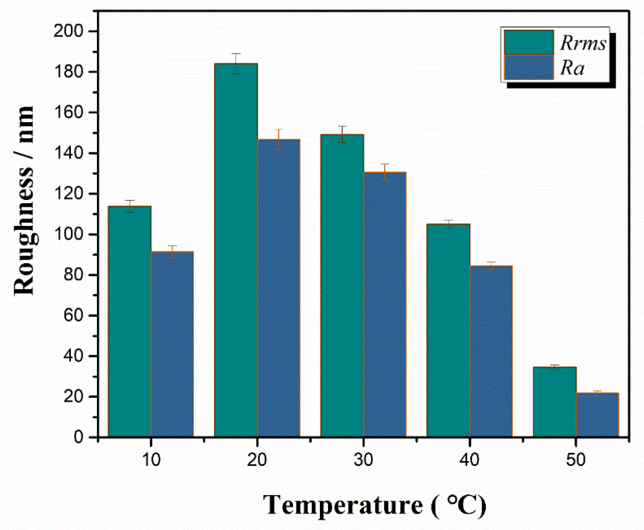
Electrolyte temperature, as a thermodynamic factor, affects the growth of the composite anodic films, resulting in its different surface roughness. As a result, PTFE nanoparticles are more easily adsorbed on rough surfaces of films, which causes a strong hydrophobicity (CA = 131.95) at 20 °C.
(2)
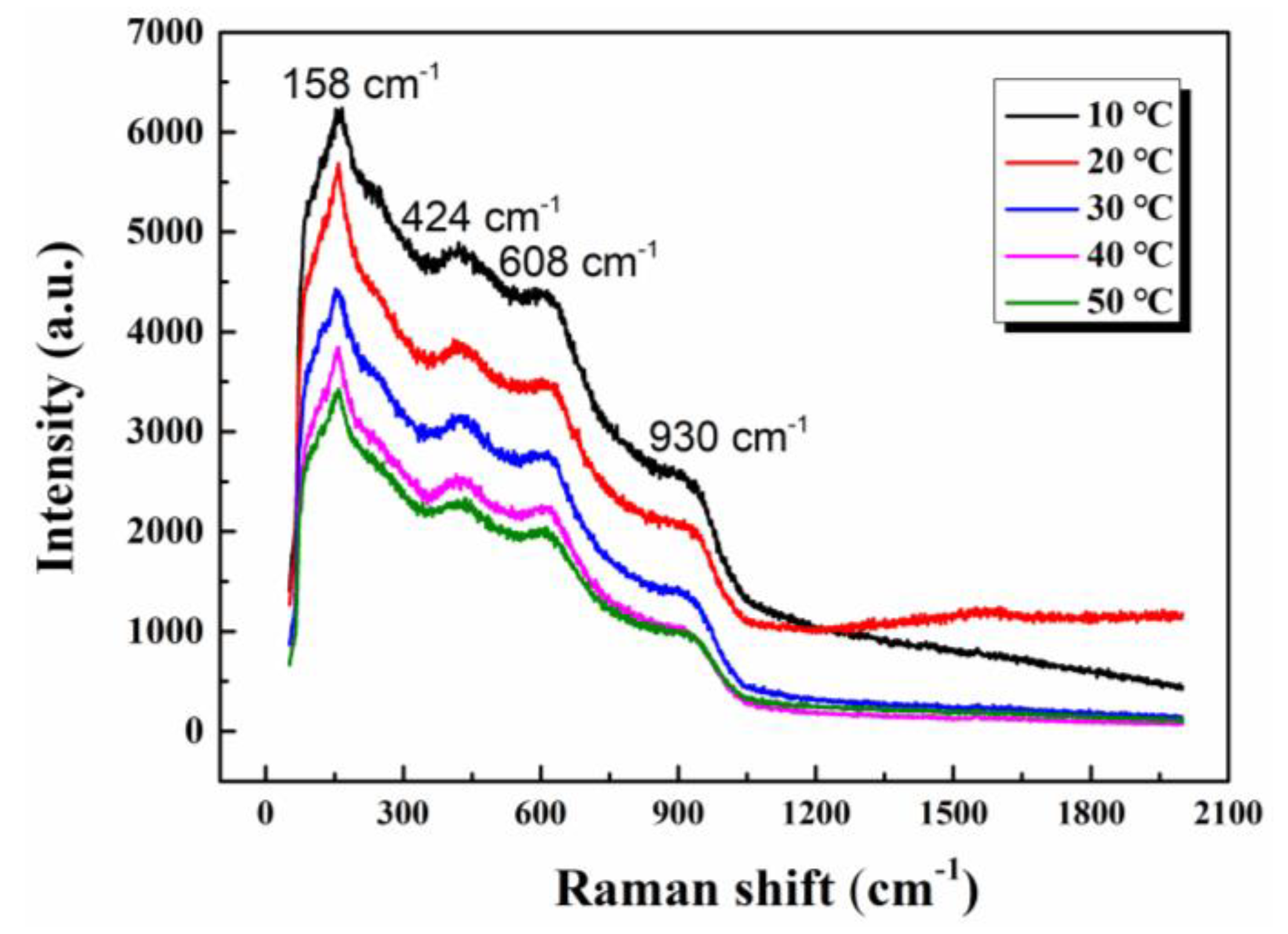
To a certain extent, the lower electrolyte temperature, the more crystalline oxides (anatase and rutile) can be obtained in the films. Under the constant current, the final voltage decreases with the electrolyte temperature. Higher final voltages do not always result in a thicker oxide film and the electrolyte temperature also has an obvious effect on the film thickness.
(3)
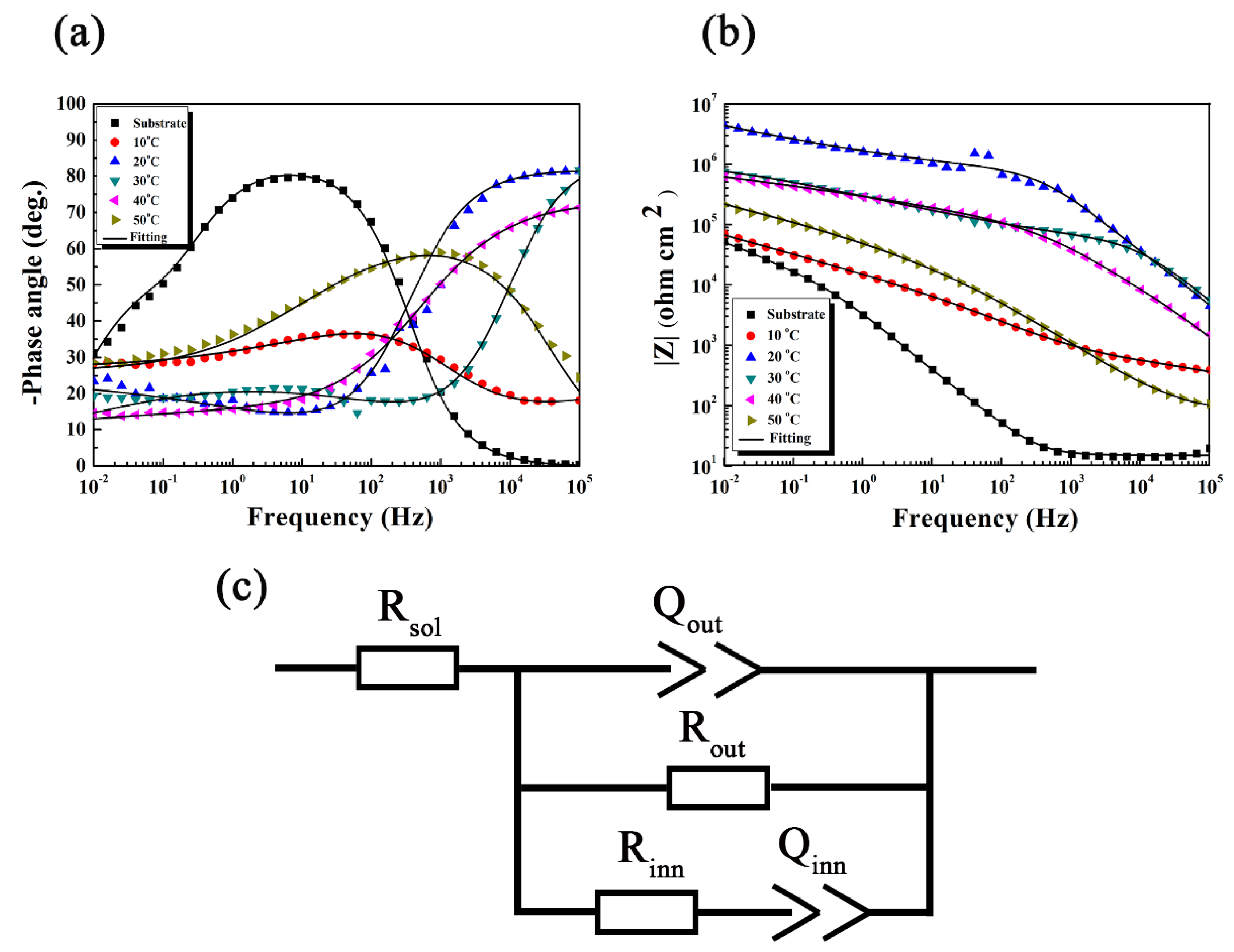
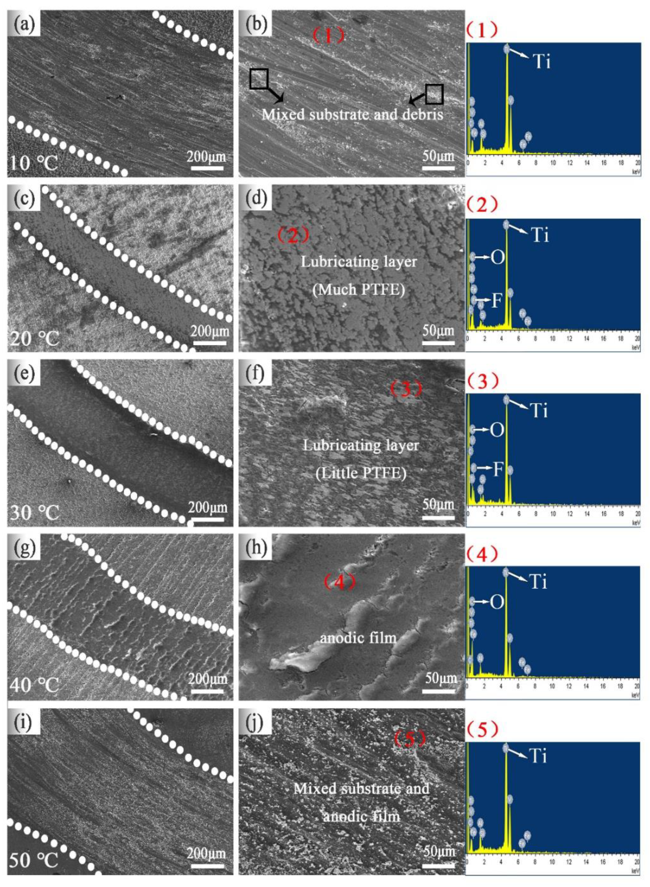
The corrosion and wear resistance of the film increased with electrolyte temperature until it reached the maximum at 20 °C. It was attributed to the PTFE particles with hydrophobicity in pores providing a physical barrier against the immersion of Cl, with the rest down to the formation of the PTFE lubricating layer.

Author Contributions

Conceptualization, Y.W. and L.W.; formal analysis, Y.W., X.D., L.L. and L.W.; funding acquisition, L.W.; investigation, Y.W., L.L., H.W., Y.L., and L.W.; project administration, L.W.; resources, L.W.; supervision, F.P. and L.W.; validation, Y.W., Z.-H.X., H.W. and L.W.; visualization, Y.W. and L.W.; writing—original draft, Y.W.; writing—review and editing, Y.W., G.Z., W.Y. and L.W. All authors have read and agreed to the published version of the manuscript.

Funding

This work was supported by the National Natural Science Foundation of China (51971040, 51701029), the Fundamental Research Funds for the Central Universities (2020CDJQY-A007), China Postdoctoral Science Foundation Funded Project (2017M620410, 2018T110942), the Chongqing Postdoctoral Scientific Research Foundation (Xm2017010).

Conflicts of Interest

No conflict of interest exits in the submission of this manuscript, and manuscript is approved by all authors for publication. I would like to declare on behalf of my co-authors that the work described was original research that has not been published previously, and not under consideration for publication elsewhere, in whole or in part.

References

  1. Pal, S.; Peršin, Z.; Vuherer, T.; Drstvenšek, I. The Effect of Ti-6Al-4V Alloy Surface Structure on the Adhesion and Morphology of Unidirectional Freeze-Coated Gelatin. Coatings 2020, 10, 434. [Google Scholar] [CrossRef]
  2. Ossowska, A.; Zieliński, A.; Olive, J.-M.; Wojtowicz, A. Influence of Two-Stage Anodization on Properties of the Oxide Coatings on the Ti–13Nb–13Zr Alloy. Coatings 2020, 10, 707. [Google Scholar] [CrossRef]
  3. Gao, K.; Wang, Z.; Jia, Q.; Zhang, B.; Mou, Z. The Utilization of Carbon Dioxide to Prepare TiCxOy Films with Low Friction and High Anti-Corrosion Properties. Coatings 2020, 10, 533. [Google Scholar] [CrossRef]
  4. Zimowski, F.; Moskalewicz, K. The Influence of Electrophoretic Deposition Parameters and Heat Treatment on the Microstructure and Tribological Properties of Nanocomposite Si3N4/PEEK 708 Coatings on Titanium Alloy. Coatings 2019, 9, 530. [Google Scholar]
  5. Ma, K.; Yu, M.; Liu, J.; Li, S.; Wu, L.; Yao, W. Effect of sodium tartrate concentrations on morphology and characteristics of anodic oxide film on titanium alloy Ti–10V–2Fe–3Al. Chin. J. Aeronaut 2016, 29, 1151–1158. [Google Scholar] [CrossRef] [Green Version]
  6. Luz, A.R.; de Souza, G.B.; Lepienski, C.M.; Siqueira, C.J.M. Tribological properties of nanotubes grown on Ti-35Nb alloy by anodization. Thin Solid Film. 2018, 660, 529–537. [Google Scholar] [CrossRef]
  7. Mehdi, M.; Farokhzadeh, K.; Edrisy, A. Dry sliding wear behavior of superelastic Ti–10V–2Fe–3Al β-titanium alloy. Wear 2016, 350–351, 10–20. [Google Scholar] [CrossRef]
  8. Ge, Y.; Xu, J.; Huan, H. Tool wear during high speed turning in situ TiCp/TiBw hybrid reinforced Ti-6Al-4V matrix composite. Chin. J. Aeronaut 2016, 29, 1425–1435. [Google Scholar] [CrossRef] [Green Version]
  9. Wang, D.; Li, H.; Yang, H.; Ma, J.; Li, G. Tribological evaluation of surface modified H13 tool steel in warm forming of Ti–6Al–4V titanium alloy sheet. Chin. J. Aeronaut 2014, 27, 1002–1009. [Google Scholar] [CrossRef] [Green Version]
  10. Wu, L.; Wen, C.; Zhang, G.; Liu, J. Influence of anodizing time on morphology, structure and tribological properties of compositeanodic films on titanium alloy. Vacuum 2017, 140, 176–184. [Google Scholar] [CrossRef]
  11. Wang, S.; Liao, Z.; Liu, Y.; Liu, W. Different tribological behaviors of titanium alloys modified by thermal oxidation and spraying diamond like carbon. Sur. Coat. Technol. 2014, 252, 64–73. [Google Scholar] [CrossRef]
  12. Koshuro, V.; Fomin, A.; Rodionov, I. Composition, structure and mechanical properties of metal oxide coatings produced on titanium using plasma spraying and modified by micro-arc oxidation. Ceram. Int. 2018, 44, 12593–12599. [Google Scholar] [CrossRef]
  13. Zubillaga, O.; Cano, F.J.; Azkarate, I.; Molchan, I.S.; Thompson, G.E.; Skeldon, P. Anodic films containing polyaniline and nanoparticles for corrosion protection of AA2024T3 aluminium alloy. Sur. Coat. Technol. 2009, 203, 1494–1501. [Google Scholar] [CrossRef]
  14. Escobar, J.; Arurault, L.; Turq, V. Improvement of the tribological behavior of PTFE-anodic film composites prepared on 1050 aluminum substrate. Appl. Surf. Sci. 2012, 258, 8199–8208. [Google Scholar] [CrossRef] [Green Version]
  15. Mei, S.; Wang, H.; Wang, W.; Tong, L.; Pan, H.; Ruan, C.; Ma, Q.; Liu, M.; Yang, H.; Zhang, L.; et al. Antibacterial effects and biocompatibility of titanium surfaces with graded silver incorporation in titania nanotubes. Biomaterials 2014, 35, 4255–4265. [Google Scholar] [CrossRef] [PubMed]
  16. Baszkiewicz, J.; Krupa, D.; Mizera, J. Corrosion resistance of the surface layers formed on titanium by plasma electrolytic oxidation and hydrothermal treatment. Vacuum 2005, 78, 143–147. [Google Scholar] [CrossRef]
  17. Wang, X.; Li, L.; Xie, Z.-H.; Yu, G. Duplex coating combining layered double hydroxide and 8-quinolinol layers on Mg alloy for corrosion protection. Electrochim. Acta 2018, 283, 1845–1857. [Google Scholar] [CrossRef]
  18. Wu, L.; Ding, X.; Zheng, Z.; Ma, Y.; Atrens, A.; Chen, X.; Xie, Z.; Sun, D.; Pan, F. Fabrication and characterization of an actively protective Mg-Al LDHs/Al2O3 composite coating on magnesium alloy AZ31. Appl. Surf. Sci. 2019, 487, 558–568. [Google Scholar] [CrossRef]
  19. Li, S.-M.; Yu, X.-M. Microstructure and abrasive wear behaviour of anodizing composite films containing SiC nanoparticles on Ti6Al4V alloy. J. Cent South Univ. 2014, 21, 4415–4423. [Google Scholar] [CrossRef]
  20. Li, S.; Zhu, M.; Liu, J.; Yu, M.; Wu, L.; Zhang, J.; Liang, H. Enhanced tribological behavior of anodic films containing SiC and PTFE nanoparticles on Ti6Al4V alloy. Appl. Surf. Sci. 2014, 316, 28–35. [Google Scholar] [CrossRef]
  21. Aliofkhazraei, M.; Rouhaghdam, A.S.; Shahrabi, T. Abrasive wear behaviour of Si3N4/TiO2 nanocomposite coatings fabricated by plasma electrolytic oxidation. Sur. Coat. Technol. 2010, 205, S41–S46. [Google Scholar] [CrossRef]
  22. Wu, H.; Zhu, L.-N.; Yue, W.; Fu, Z.-Q.; Kang, J.-J. Wear-resistant and hydrophobic characteristics of PTFE/CF composite coatings. Prog. Org. Coat 2019, 128, 90–98. [Google Scholar] [CrossRef]
  23. Liu, Y.; Xu, N.; Wang, Y.; Yao, Y.; Xiao, H. Preparation and tribological properties of hybrid PTFE/Kevlar fabric self-lubricating composites. Sur. Coat. Technol. 2019, 361, 196–205. [Google Scholar] [CrossRef]
  24. Arrabal, R.; Matykina, E.; Viejo, F.; Skeldon, P.; Thompson, G.E. AC plasma electrolytic oxidation of magnesium with zirconia nanoparticles. Appl. Surf. Sci. 2008, 254, 6937–6942. [Google Scholar] [CrossRef]
  25. Oh, S.H.; Finones, R.R.; Daraio, C.; Chen, L.H.; Jin, S. Growth of nano-scale hydroxyapatite using chemically treated titanium oxide nanotubes. Biomaterials 2005, 26, 4938–4943. [Google Scholar] [CrossRef] [PubMed]
  26. Yin, X.; Mu, P.; Wang, Q.; Li, J. Superhydrophobic ZIF-8 based dual-layer coating for enhanced corrosion protection of Mg alloy. ACS Appl. Mater. Interfaces 2020, 12, 35453–35463. [Google Scholar] [CrossRef]
  27. Blawert, C.; Dietzel, W.; Ghali, E.; Song, G. Anodizing Treatments for Magnesium Alloys and Their Effect on Corrosion Resistance in Various Environments. Adv. Eng. Mater. 2006, 8, 511–533. [Google Scholar] [CrossRef]
  28. Krasicka-Cydzik, E. Gel-like layer development during formation of thin anodic films on titanium in phosphoric acid solutions. Corros. Sci. 2004, 46, 2487–2502. [Google Scholar] [CrossRef]
  29. Bharathiraja, B.; Selvakumari, I.A.E.; Jayamuthunagai, J.; Kumar, R.P.; Varjani, S.; Pandey, A.; Gnansounou, E. Biochemical conversion of biodiesel by-product into malic acid: A way towards sustainability. Sci. Total Environ. 2020, 709, 136206. [Google Scholar] [CrossRef]
  30. Wu, C.; Liu, Q.; Chen, R.; Liu, J.; Zhang, H. Fabrication of ZIF-8@SiO2 Micro/Nano Hierarchical Superhydrophobic Surface on AZ31 Magnesium Alloy with Impressive Corrosion Resistance and Abrasion Resistance. ACS Appl. Mater. Interfaces 2017, 9, 11106–11115. [Google Scholar] [CrossRef]
  31. Li, S.; Yao, W.; Liu, J. Study on anodic oxidation process and property of composite film formed on Ti–10V–2Fe–3Al alloy in SiC nanoparticle suspension. Sur. Coat. Technol. 2015, 277, 234–241. [Google Scholar] [CrossRef]
  32. Zheludkevich, M.L.; Tedim, J.; Ferreira, M.G.S. “Smart” coatings for active corrosion protection based on multi-functional micro and nanocontainers. Electrochim. Acta 2012, 82, 314–323. [Google Scholar] [CrossRef]
  33. de Miera, M.S.; Curioni, M.; Skeldon, P.; Thompson, G.E. The behaviour of second phase particles during anodizing of aluminium alloys. Corros. Sci. 2010, 52, 2489–2497. [Google Scholar] [CrossRef]
  34. Byeon, A.; Zhao, M.Q.; Ren, C.E.; Halim, J.; Kota, S.; Urbankowski, P.; Anasori, B.; Barsoum, M.W.; Gogotsi, Y. Two-Dimensional Titanium Carbide MXene as a Cathode Material for Hybrid Magnesium/Lithium-Ion Batteries. ACS Appl. Mater. Interfaces 2017, 9, 4296–4300. [Google Scholar] [CrossRef] [PubMed]
  35. Xia, X.; Zhitomirsky, I.; McDermid, J.R. Electrodeposition of zinc and composite zinc–yttria stabilized zirconia coatings. J. Mater. Process. Technol. 2009, 209, 2632–2640. [Google Scholar] [CrossRef]
  36. Liu, J.H.; Wu, G.L.; Yu, M.; Wu, L. Influence of incremental rate of anodising current on roughness and electrochemical corrosion of oxide film on titanium alloy Ti–10V–2Fe–3Al. Surf. Eng. 2013, 28, 406–411. [Google Scholar] [CrossRef]
  37. Miyakita, N.; Tanigaki, N.; Morishige, T.; Takenaka, T. Effect of Voltage on Mg-Li-Al Alloy Anodic Oxide Film. Mater. Sci. Forum 2018, 941, 1194–1197. [Google Scholar] [CrossRef]
  38. Li, C.; Wu, L.; Zhao, S.; Jiang, L.; Yang, Y.; Zhang, K.; Zhu, X. Essential influence of electrode and electrolyte temperatures on the anodizing process of Ti. Chem. Phys. Lett. 2019, 722, 6–11. [Google Scholar] [CrossRef]
  39. Yan, H.; Li, W.; Li, H.; Fan, X.; Zhu, M. Ti3C2 MXene nanosheets toward high-performance corrosion inhibitor for epoxy coating. Prog. Org. Coat. 2019, 135, 156–167. [Google Scholar] [CrossRef]
  40. Dong, G.Z.; Fan, H.Q.; Zhu, Y.N.; Pan, X.B.; Jiang, X.B. Effects of hyperthermia induced crystalline aggregation on properties of TiO2thin films. Surf. Eng. 2014, 30, 600–605. [Google Scholar] [CrossRef]
  41. Wang, Y.; Dou, H.; Wang, J. Three-dimensional porous MXene/layered double hydroxide composite for high performance super capacitors. J. Power Sources 2016, 327, 221–228. [Google Scholar] [CrossRef]
  42. Zhang, G.; Wu, L.; Tang, A. Growth behavior of MgAl-layered double hydroxide films by conversion of anodic films on magnesium alloy AZ31 and their corrosion protection. Appl. Surf. Sci. 2018, 456, 419–429. [Google Scholar] [CrossRef]
  43. Zhang, G.; Wu, L.; Tang, A.; Ma, Y.; Song, G.-L.; Zheng, D.; Jiang, B.; Atrens, A.; Pan, F. Active corrosion protection by a smart coating based on a MgAl-layered double hydroxide on a cerium-modified plasma electrolytic oxidation coating on Mg alloy AZ31. Corros. Sci. 2018, 139, 370–382. [Google Scholar] [CrossRef] [Green Version]
Figure 1. Fabrication illustration of composite anodic films.
Coatings 10 01109 g001
Figure 2. FE-SEM images and the corresponding EDS, contact angles (Cas) of composite anodic films fabricated at different temperatures: (a,b) (1) 10 °C; (c,d) (2) 20 °C; (e,f) (3) 30 °C; (g,h) (4) 40 °C; (i,j) (5) 50 °C.
Coatings 10 01109 g002
Figure 3. Three-dimensional atomic force microscope (AFM) figures of composite anodic films at different temperatures.
Coatings 10 01109 g003
Figure 4. Root-mean-square roughness and average roughness of composite anodic films at different temperatures.
Coatings 10 01109 g004
Figure 5. Cross-sectional FE-SEM micrographs of the composite anodic films fabricated at different temperatures. (a) 10 °C, (b) 20 °C, (c) 30 °C, (d) 40 °C, (e) 50 °C.
Coatings 10 01109 g005
Figure 6. Voltage–time plots of composite anodic films fabricated at different temperatures.
Coatings 10 01109 g006
Figure 7. Raman spectra of composite anodic films fabricated at different temperatures.
Coatings 10 01109 g007
Figure 8. Potentiodynamic polarization curves recorded in 3.5 wt.% NaCl solution for the composite anodic film fabricated at different temperatures.
Coatings 10 01109 g008
Figure 9. (a,b) are EIS plots of composite anodic films fabricated at different temperatures; (c) equivalent circuits used to fit EIS plots.
Coatings 10 01109 g009
Figure 10. Friction coefficients of composite anodic films fabricated at different temperatures.
Coatings 10 01109 g010
Figure 11. (a) Cross-section of wear tracks and (b) wear rates of composite anodic films fabricated at different temperatures.
Coatings 10 01109 g011
Figure 12. The SEM and EDS images of the worn surface for composite anodic films fabricated at different temperatures: (a,b) (1) 10 °C; (c,d) (2) 20 °C; (e,f) (3) 30 °C; (g,h) (4) 40 °C; (i,j) (5) 50 °C.
Coatings 10 01109 g012
Figure 13. The corresponding lubrication mechanism of composite anodic films fabricated at different temperatures during the wear test. (a) 10 °C and 50 °C (b) 20 °C and 30 °C (c) 40 °C.
Coatings 10 01109 g013
Table 1. The nominal chemical composition of Ti-10V-2Fe-3Al (wt.%).
VFeAlCOTi
10.0002.1003.100<0.050<0.010balance
Table 2. The analysis results of corresponding EDS points in Figure 2.
Elements10 °C (At.%)
(1)
20 °C (At.%)
(2)
30 °C (At.%)
(3)
40 °C (At.%)
(4)
50 °C (At.%)
(5)
O K47.5919.299.9840.6710.83
F K4.2748.5435.8823.3710.26
Al K1.270.420.490.720.91
Ti K21.3912.3218.1218.1738.64
V K2.161.641.812.204.13
Fe K0.340.240.330.150.94
Table 3. Corrosion potential (Ecorr) and corrosion current density (icorr).
SamplesEcorr (V/SCE)icorr (A·cm−2)
Substrate−0.533.26 × 10−6
10 °C0.275.98 × 10−7
20 °C0.146.75 × 10−8
30 °C−0.091.01 × 10−7
40 °C−0.121.53 × 10−7
50 °C0.072.51 × 10−7
Table 4. Fitted parameters for the electrochemical impedance spectroscopy (EIS) spectrum depicted in Figure 9.
ParameterRsol(Ω·cm2)Qout (S sn·cm−2)noutRout (Ω·cm2)Qinn (S sn·cm−2)ninnRinn (Ω·cm2)Χ2
Substrate14.645.44 × 10−50.9727.45 × 1046.03 × 10−50.7542.51 × 1034.51 × 10−3
10 °C12.233.32 × 10−50.3001.72 × 1073.75 × 10−60.6289.55 × 1027.53 × 10−4
20 °C10.061.64 × 10−90.9111.54 × 10125.71 × 10−70.2746.15 × 1059.21 × 10−3
30 °C15.655.75 × 10−90.9081.53 × 1081.81 × 10−60.3174.29 × 1042.78 × 10−3
40 °C11.071.47 × 10−80.8142.37 × 1062.15 × 10−60.1918.77 × 1034.20 × 10−3
50 °C15.361.73 × 10−60.7191.76 × 1061.04 × 10−50.2931.73 × 1031.04× 10−3
Table 5. The analysis results of corresponding EDS points in Figure 12.
Elements10 °C (At.%)
(1)
20 °C (At.%)
(2)
30 °C (At.%)
(3)
40 °C (At.%)
(4)
50 °C (At.%)
(5)
O K7.9336.1154.1465.7310.05
F K0.0418.3412.260.210.09
Al K3.620.381.201.345.30
Si K0.730.650.090.030.90
Ti K61.0210.8321.6519.2659.07
V K6.111.253.322.357.42
Fe K1.460.050.470.280.88
Publisher’s Note: MDPI stays neutral with regard to jurisdictional claims in published maps and institutional affiliations.

